


42VMC14-H
Carrier 42VMC14-H, 42VMC24-H, 38VMC18A-H, 42VMC18A-H, 38QG24-H Service And Maintenance Manual
...
03502566
SERVICE & MAINTENANCE MANUAL
Revision : (0) - 2009
Specifications are subject to change without notice according to Carrier Policy of continuous development.

TABLE OF CONTENTS
PAGE NO.
1. Precautions for Service & Maintenance 1
2. Split System Description 2
3. Unit Model Designation 3
4. Unit Models & Part Numbers 3
5. Options 4
6. System Operating Limits 5
7. System Safety Protections 5
8. Wiring Diagrams 6
9. Field Electrical Connections Matching 7
10. Refrigeration Cycle – 53QG Series 8
11. Replacing Batteries of Remote Control 10
12. Emergency Operation of Air-Conditioner 11
13. Standard and Optional Air Filters 12
14. Air Filter Cleaning 13
15. Indoor Unit Cleaning 14
16.
Considerations After Operational Season and Before Long
Shutdown Period Of Air Conditioner
14
17. Periodical Checks 15
18. Self Diagnostic Function For Malfunction Detection 16
19. Trouble Shooting 17
1
1. PRECAUTIONS FOR SERVICE AND MAINTENANCE
SAFETY CONSIDERATIONS
• Installation of air conditioning equipment can be hazardous due to system pressures and
electrical components.
• The installation of the air conditioner must be done by Carrier or one of Carrier authorized
dealers.
WARNING
• This installation manual describes the installation procedures of Carrier split room air
conditioner consisting of an outdoor unit and an indoor unit manufactured by Carrier.
What is not covered in Carrier warranty?
1- Failure due to wrong electrical connections between the electrical power supply and
circuit breaker of air conditioner leading to fire due to short-circuiting. As these electrical
connections are owner’s responsibility.
2- Failure due to Misuse, Abusing, overloading, negligence of air filters cleaning and
negligence of instructions included in the owner’s manual.
3- Failure due to Accident / Weather Natural catastrophe, accident due to bad weather
(Hail Storm, Sand Storm, lightning, Flooding, Acid Rain and Air Borne fallout, etc).
4- Failure due to damages during transport done through the owner.
5- Failure due to any modifications in the product done through the owner and not done by
Carrier or one of Carrier authorized dealers.
6- Failure due to Installation done through the owner and not done by Carrier or one of
Carrier authorized dealers.
7- Failure due to Service and Maintenance done through the owner and not done by Carrier
or one of Carrier authorized dealers.
8- Failure due to repair by using non-genuine Carrier Parts, or substituting other than
Carrier parts done through the owner and not done by Carrier or one of Carrier
authorized dealers.
9- Product normal sound ( refrigerant – moving parts )
10- Inconvenience or commercial loss is not covered.
The decision of Carrier in ascertaining the same will be final. Any such repairs will be carried -
out at the expense of the owner ( purchaser ).
!
2
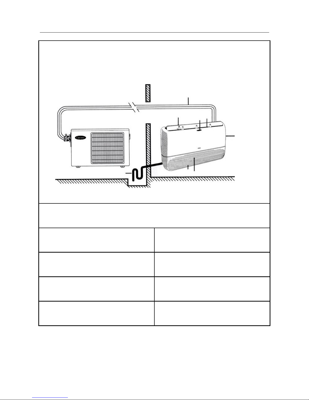
Outdoor Unit
2. SPLIT SYSTEM DESCRIPTION
1: Remote control signal receiver.
2: Operating status leds. 6: Supply air outlet.
3: Supply air flap. 7: Characteristics nameplate.
4: Air return grille. 8: Inter connecting tubing.
5: Air filter ( behind return grille ). 9: Condensate drain line.
Floor/Wall/Ceiling Split System
53VMC14-18-24
4
6
3
Indoor Unit
3
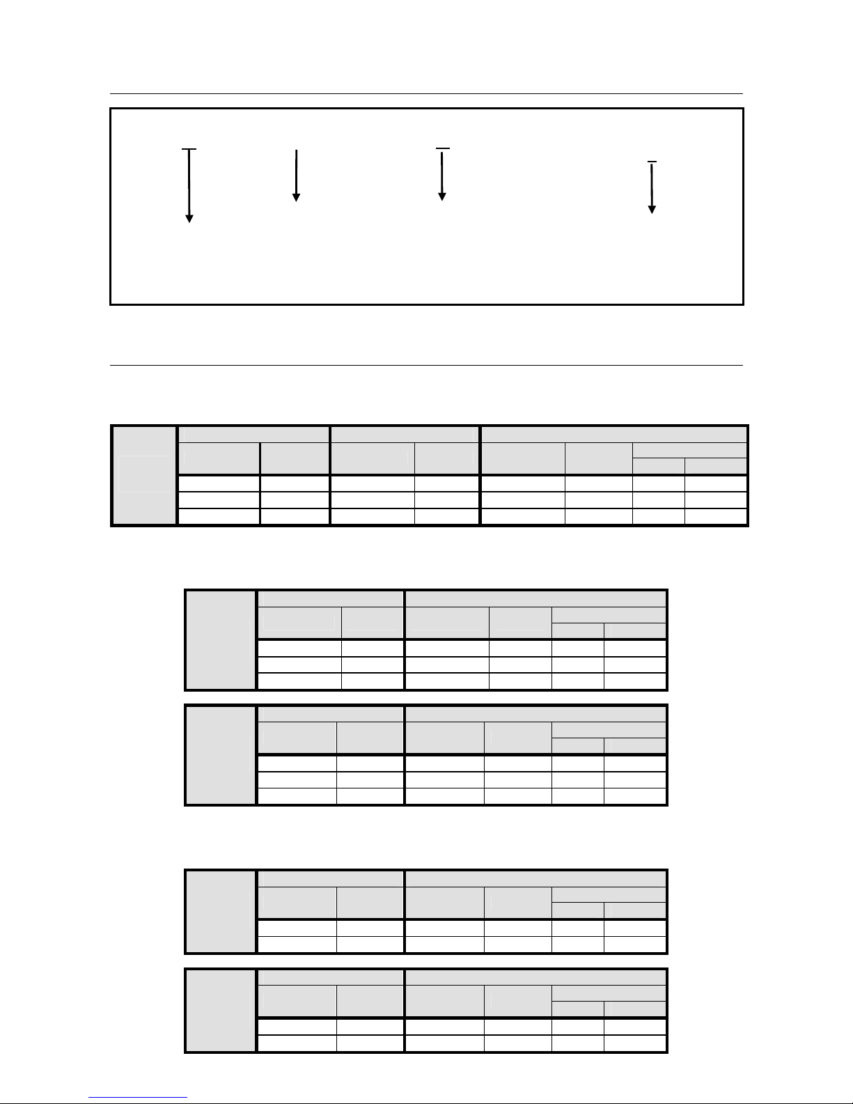
3. UNIT MODEL DESIGNATION
4. UNIT MODELS & PART NUMBERS
SPLIT SYSTEMS FOR LOCAL MARKET
System Indoor Unit Outdoor Unit
Compressor
Model P/N Model P/N Model P/N
Type Supplier
53VMC14-H
46303279 42VMC14-H 46303290 38VMC14-H
46303278 Rotary LG
53VMC18A-H
46303118 42VMC18A-H 46303276 38VMC18A-H 46303117 Rotary Hitachi
HEAT
PUMP
53VMC24-H
46303359 42VMC24-H 46303292 38QG24-H
46302128 Rotary LG
SPLIT SYSTEMS FOR MILD AMBIENT EXPORT MARKETS
Indoor Unit Outdoor Unit
Compressor
Model P/N Model P/N
Type Supplier
42VMC14-H
46303221 38QG15-H
46303300 Rotary Mitsushita
42VMC18A-H
46303533 38VMC18A-H 46303534 Rotary Hitachi
HEAT
PUMP
42VMC24-H
46303233 38QG24-H
46303644 Rotary LG
Indoor Unit Outdoor Unit
Compressor
Model P/N Model P/N
Type Supplier
42VMC14-C
46303293 38QG15-C
46302110 Rotary Mitsushita
42VMC18-C
46303294 38QG18-C
46303517 Rotary Mitsushita
COOL
ONLY
42VMC24-C
46303295 38QG24-C
46303365 Rotary Mitsushita
SPLIT SYSTEM FOR HIGH AMBIENT EXPORT MARKETS
Indoor Unit Outdoor Unit
Compressor
Model P/N Model P/N
Type Supplier
42VMC18-H
46303219 38QG18-H
46303516 Rotary Mitsushita
HEAT
PUMP
42VMC24-H
46303220 38QG24-H
46303363 Rotary Mitsushita
Indoor Unit Outdoor Unit
Compressor
Model P/N Model P/N
Type Supplier
42VMC18-C
46303294 38QG18-C
46303517 Rotary Mitsushita
COOL
ONLY
42VMC24-C
46303295 38QG24-C
46303365 Rotary Mitsushita
VMC
QG
42 = Indoor Unit
38 =Outdoor Unit
18
System
Cooling Capacity
At ISO Conditions
14 = 14,000 Btu/hr
18 = 18,000 Btu/hr
24 = 24,000 Btu/hr
Unit Family
H
C
Unit Type
H = Heat Pump
C = Cool Only
42
38
4
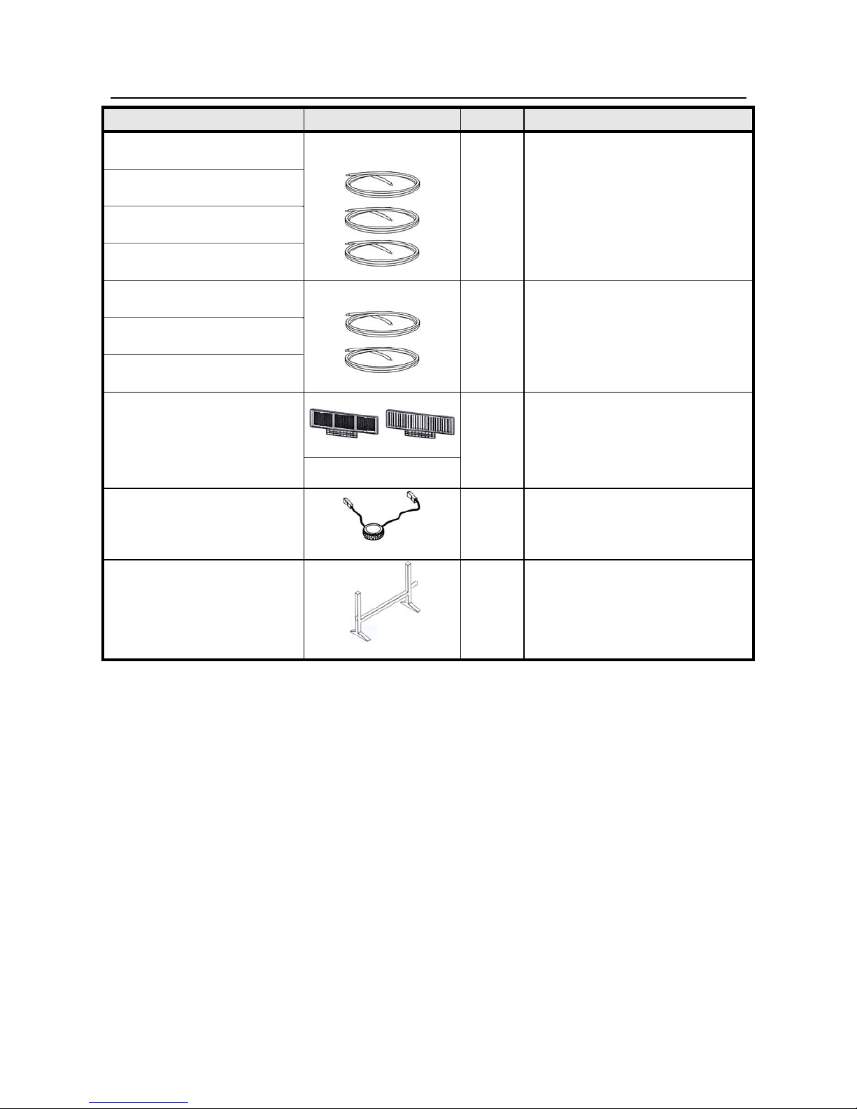
5. OPTIONS
DESCREPTION CONFIGURATION QTY USAGE
Electrical Cables Set
for Heat Pump System
Main Power cable
Outdoor Unit–Circuit Breaker
Power cable
Outdoor Unit – Indoor Unit
Control & Defrost cable
Outdoor Unit–Circuit Breaker
P/N : 02500894
Set of 3
To electrically connect between
circuit breaker, outdoor and
indoor units
Electrical Cables Set
for Cool Only System
Main Power cable
Outdoor Unit – Indoor Unit
Power & Control cable
Outdoor Unit – Indoor Unit
P/N : 02500893
Set of 2
To electrically connect between
circuit breaker, outdoor and
indoor units
Optional set of air filters
(Carbon air filter + Photocatalytic air filter)
P/N : 02802563
( for 42VMC14-18-24 )
Set of 2
To eliminate odor and cigarette
smoke in the room air
respectively.
PTC starting device for
38QG15-18-24
P/N : 02501579
1
To start the compressor in
outdoor unit at low voltage down
187V
Floor support for indoor units
42VMC14-18-24
P/N : 46300822
1
To mount the indoor unit on the
floor in case of impossibility of
mounting the unit on the wall
5
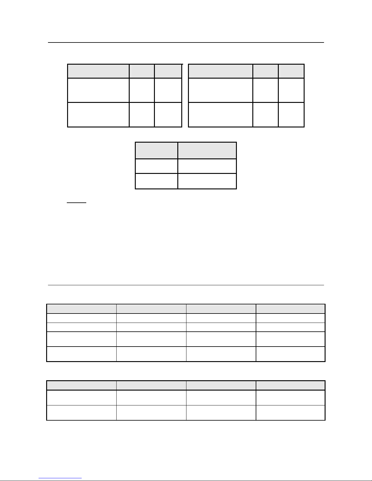
6. SYSTEM OPERATING LIMITS *
COOLING
HEATING
Difference
Dry Bulb
Temp. C°
Wet Bulb
Temp. C°
Difference
Dry Bulb
Temp. C°
Wet Bulb
Temp. C°
Indoor temperature
Maximum
Minimum
32
21
23
15
Indoor temperature
Maximum
27
-
Outdoor temperature
Maximum
Minimum
55
20
-
-
Outdoor temperature
Maximum
21
-
MAIN POWER SUPPLY
Difference
Nominal
200-240V/1PH/50HZ
Min. Voltage 187
Max. Voltage 264
NOTES:
* When the unit is operated above or below these limits for a long time, system diagnostics may detect
a malfunction and the unit will not operate properly.
** During heat pump operation the system will undergo several defrost cycles to remove ice that might
collect on the outdoor unit in very low ambient temperature.
After completion of defrosts cycle, the system will normally operate.
7. SYSTEM SAFETY PROTECTION
7-1 FOR HEAT PUMP SYSTEM
PROTECTION TYPE PROTECTION EFFECT OPERATION MODE WHEN ON
Cold draft prevention Indoor fan off Heating mode During unit operation
Defrost cycle Indoor fan off Heating mode During unit operation
Indoor coil
Freeze protection
Compressor off Cooling mode During unit operation
Against frequent
Compressor cycling
Compressor
Time delay
Cooling or heating
modes
At unit start-up or change
of operating mode
7-2 FOR COOL ONLY SYSTEM
PROTECTION TYPE PROTECTION EFFECT OPERATION MODE WHEN ON
Indoor coil
Freeze protection
Compressor off Cooling mode During unit operation
Against frequent
Compressor cycling
Compressor
Time delay
Cooling mode
At unit start-up or change
of operating mode
6
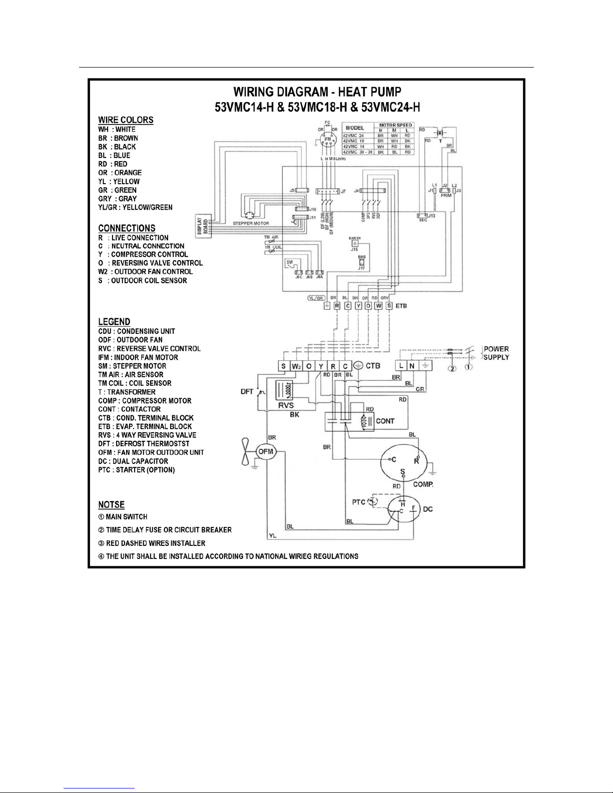
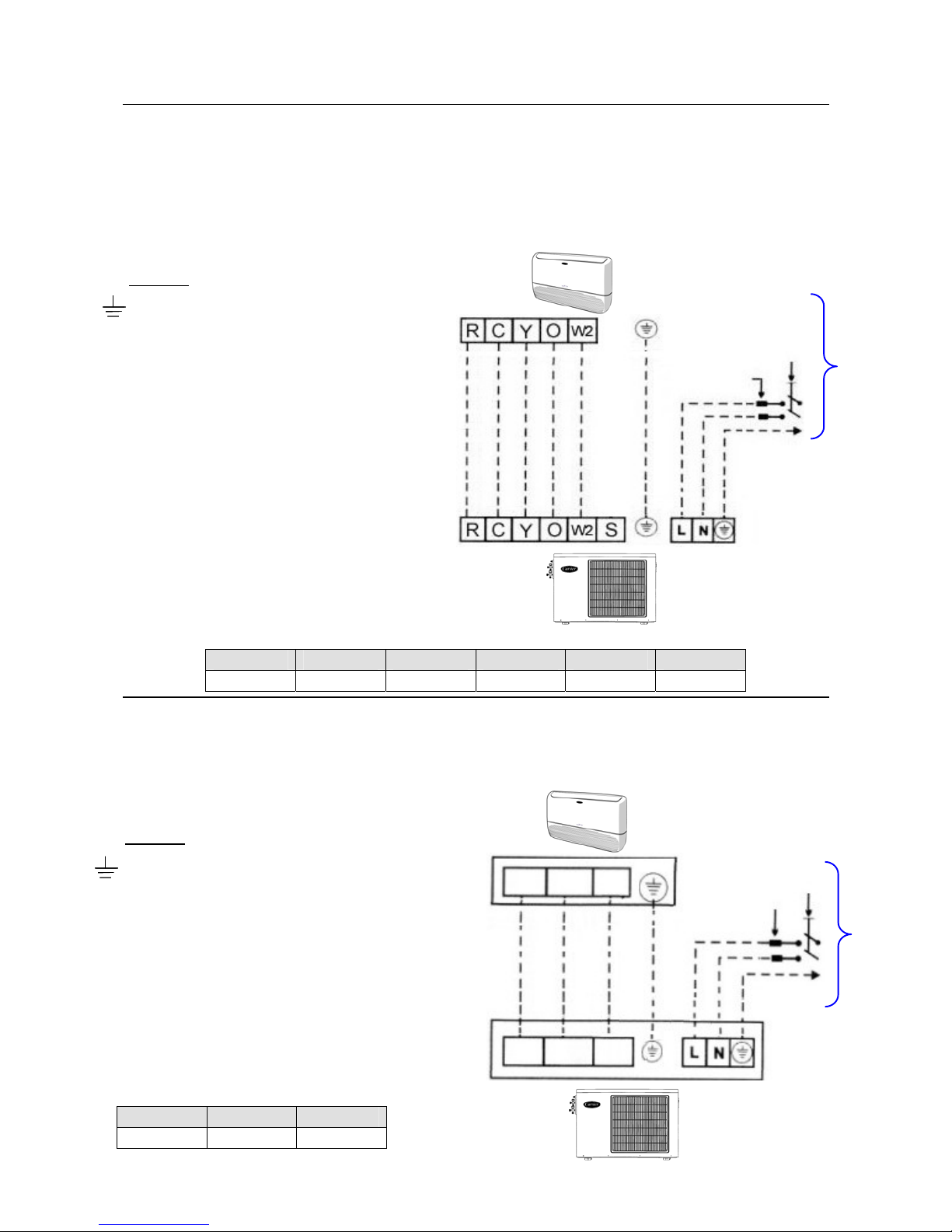
8. WIRING DIAGRAMS
7
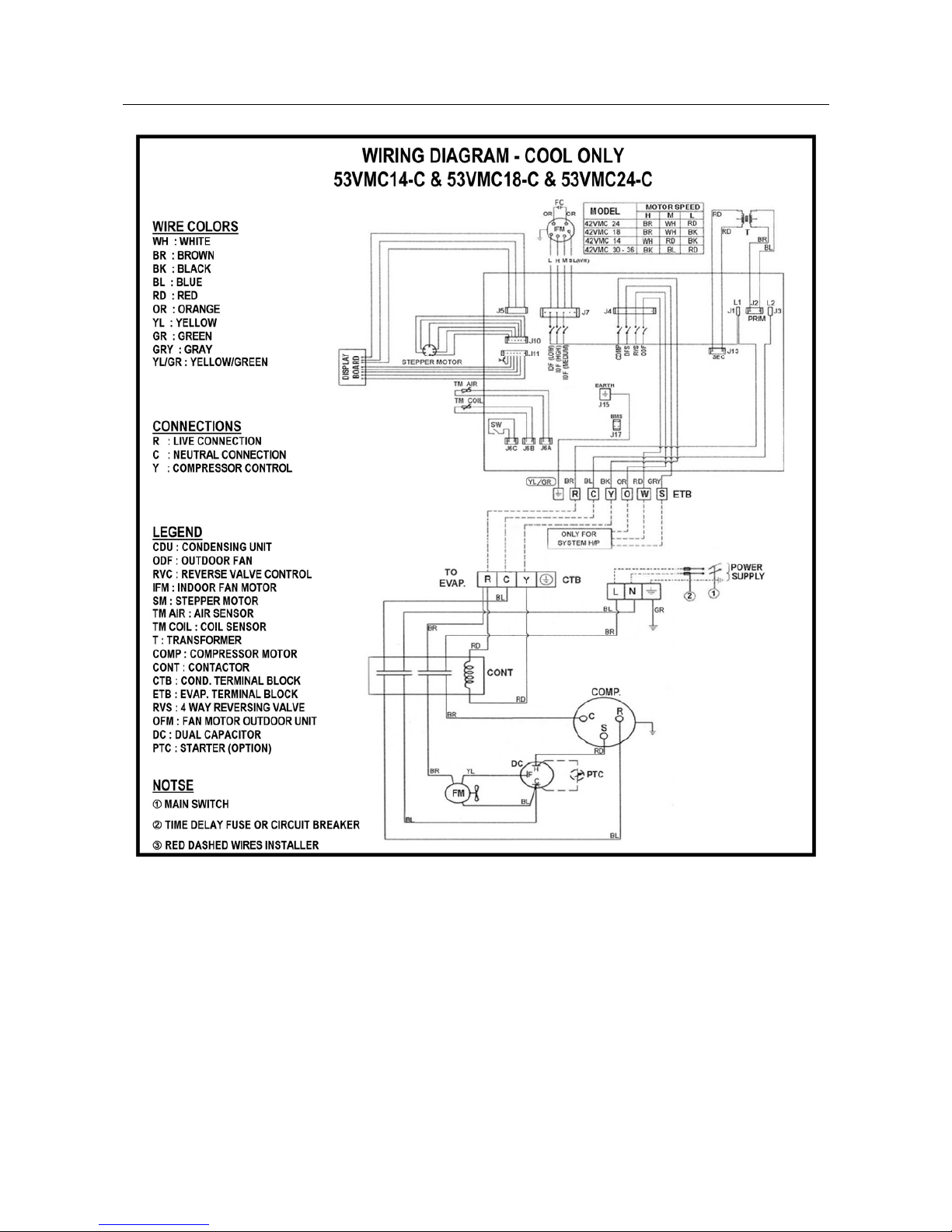
WIRING DIAGRAMS (Cont.)
8
LEGEND
Earth
L Live power supply.
N Neutral power supply.
R Live connection indoor/outdoor unit.
C Neutral connection indoor/outdoor unit.
Y Compressor control.
O Reversing valve control.
W2 Outdoor fan motor control.
S Outdoor coil sensor.
LEGEND
Earth
L Live power supply.
N Neutral power supply.
R Live connection indoor/outdoor unit.
C Neutral connection indoor/outdoor unit.
Y
Compressor control.
9. FIELD ELECTRICAL CONNECTIONS MATCHING
- Connect the power supply to the outdoor unit and then get the power required for the indoor unit from the outdoor unit.
- Refer to wiring diagrams and stickers-caution sticked inside the outdoor & indoor units.
9-1 CONNECTING ELECTRICAL WIRING FOR HEAT PUMP SYSTEM
Sizes of electrical wires connecting outdoor and indoor units
R C Y O W2 S
1 mm
2
1 mm
2
1 mm2 1 mm2 1 mm2 1 mm2
9-2 CONNECTING ELECTRICAL WIRING FOR COOL ONLY SYSTEM
Sizes of electrical wires connecting
outdoor and indoor units
R C Y
1 mm
2
1 mm
2
1 mm2
200 - 240V ~ 50Hz
Circuit
Breake
r
Main
Switch
RCY
RCY
200 - 240V ~ 50Hz
Circuit
Breake
r
Main
Switch
Indoor Unit
Outdoor
Unit
Outdoor
Unit
Indoor Unit
9
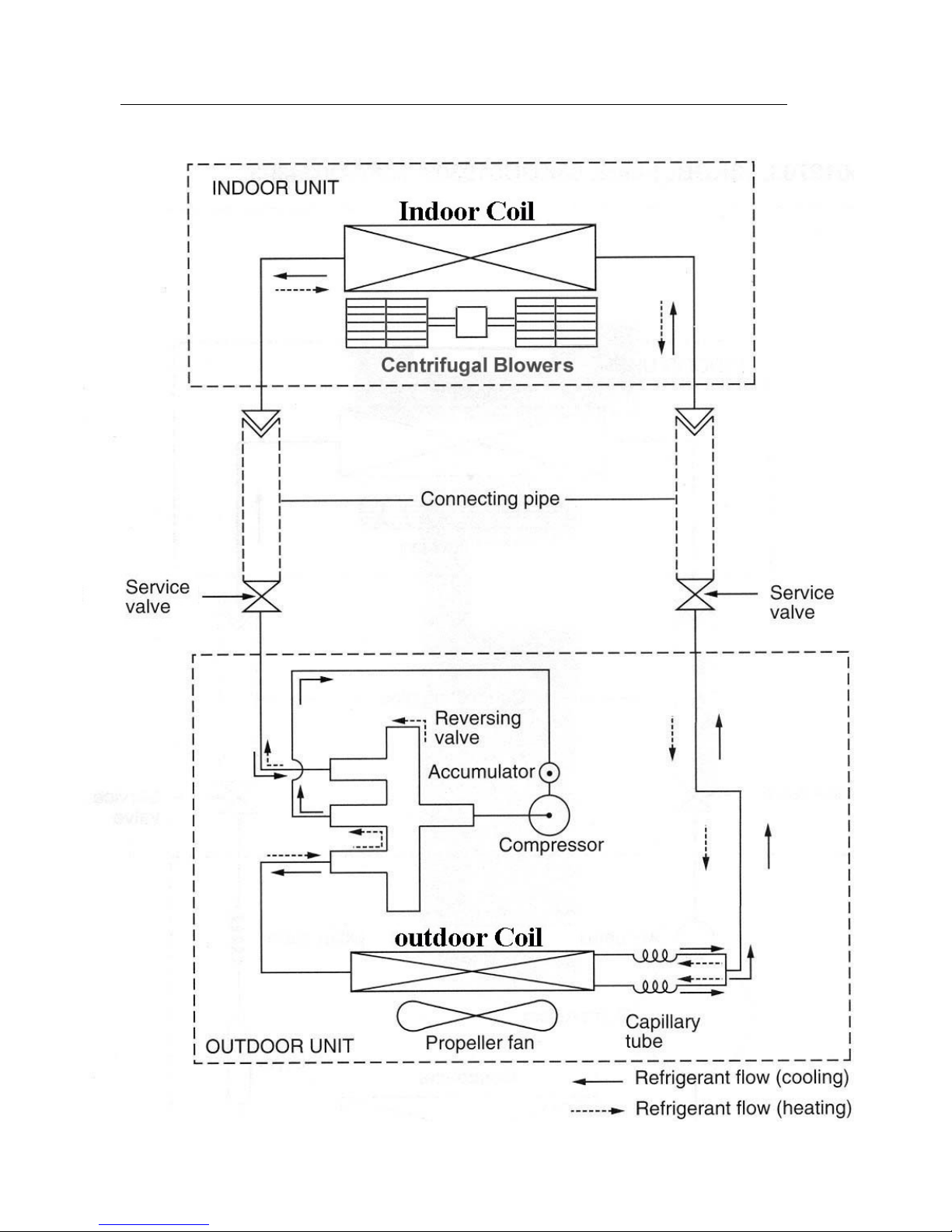
11. REFRIGERATION CYCLE – 53VMC SERIES
HEAT PUMP SYSTEM
10
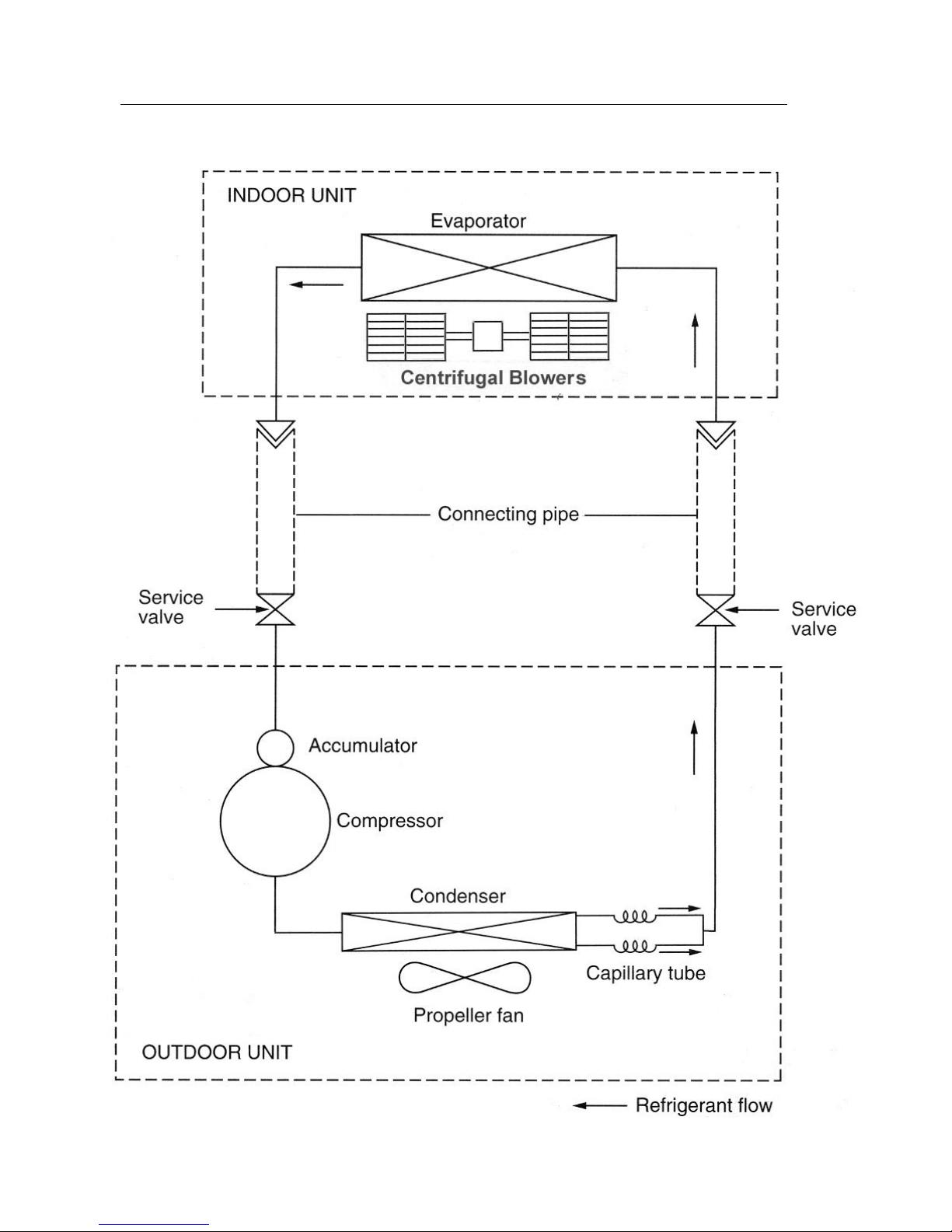
REFRIGERATION CYCLE – 53VMC SERIES (Cont.)
COOL ONLY SYSTEM
11
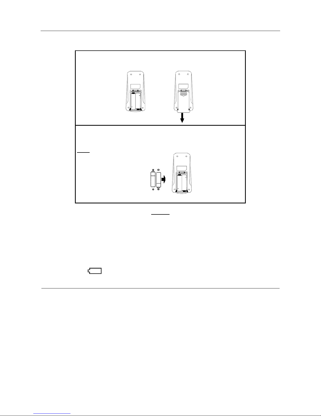
12. REPLACING BATTERIES OF REMOTE CONTROL Model 42QG&42VMC 14-18-24
12-1 HOW TO INSERT BATTERIES:
(a) Remove the cover of battery compartment at the back of the remote
control by pressing the tab toward inside, in the direction of the
arrow.
(b) Mount the two-battery size AAA 1.5 Volt supplied with the remote
control. Then close the cover of the battery component.
Note:
During mounting of batteries
check battery symbols (+, -)
indicated in batteries
compartment.
NOTES:
1. The remote control uses two alkaline batteries (1.5V, LRO03x2).
2. Do not use used batteries or batteries of different types, as this may cause the air conditioner to
malfunction.
3. Batteries should only be changed after turning OFF the air conditioner.
4. The average battery life during normal use is approximately one year.
5. When the symbol appears in the display of the remote control, this indicates that the batteries are
exhausted and required to be replaced.
WHEN DIRECTING THE TRANSMITTER OF WIRELESS REMOTE CONTROL TO THE RECEIVER
OF INDOOR UNIT FROM A CERTAIN LOCATION, CHECK THE FOLLOWING POINTS:
1- Avoid direct sunlight on the receiver of indoor unit, which may interfere with good signal reception
2- No obstructions such as curtains or plants should be between the remote control and the receiver of
indoor unit.
3- The maximum operating range for the remote control is approximately 5 meters.
4- The remote control must be directed toward the receiver of indoor unit when pressing the buttons of the
desired functions. An acoustical acknowledgement sound (beep) will indicate that signal has been received.
12
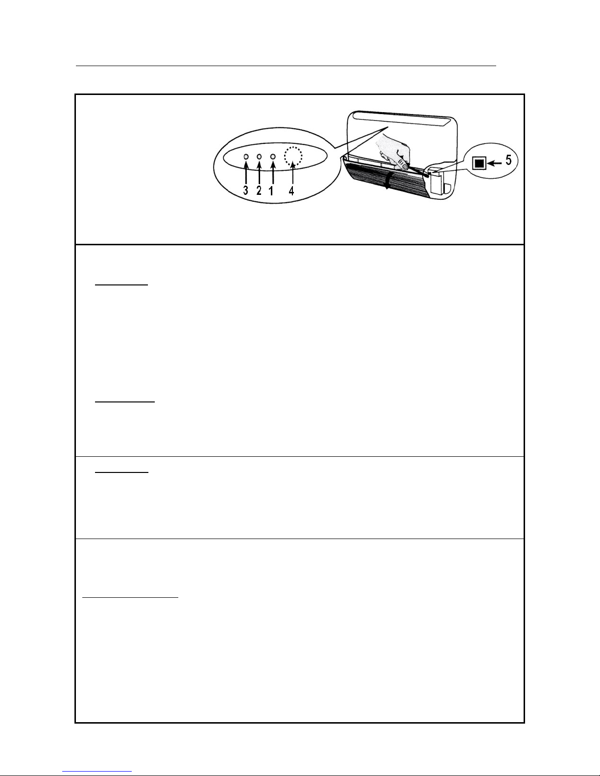
13. EMERGENCY OPERATION OF AIR-CONDITIONER
INDOOR UNITS 42VMC14-18-24-30-36 SERIES
Indoor unit LED’s
• GREEN LED (1) shows the following conditions :
- Fault codes (diagnostic);
- During normal operation, the LED is lit.
Once a failure occurs, the LED flashes at intervals of 0.5 seconds. The fault code is deduced from
the number of times the LED flashes. Between one flash cycle and the next a pause of 5 seconds
elapses.
If the timer mode is active and the unit is immediately restarted after a stop, this LED flashes until a
new signal is sent to the indoor unit.
• YELLOW LED (2) shows the operation in timer mode.
During this operation in this operating mode, the LED is lit .
If the time mode is active and the unit is immediately restarted after a stop, this LED flashes until a
new signal is sent to the indoor unit.
• RED LED (3) gives the following information:
- During normal operation, the LED is OFF;
- During defrost the LED is lit;
- During the test for wired connection, the LED
flashes at 1- second intervals.
Button (5) : “EMERGENCY”
Can be used when the remote control is lost or inoperative.
Use a screwdriver to press the push-button.
Emergency operation:
When the unit is in the OFF mode and the emergency is pressed for 5 seconds, the system will
operate as follows:
- Automatic mode.
- Temperature preset to 22ºC.
- Automatic fan speed.
- Louvers set automatically according to operating mode.
- Timer Functions are inactive.
When a signal is received by the remote control, system operates accordingly.
1 : Green Led
2 : Yellow Led
3 : Red Led
4 : Remote control
signal receiver
5 : “Emergency” button
 Loading...