


30XV160
Table of contents
 Loading...
Carrier 30XV160, 30XV225, 30XV275, 30XV300, 30XV250 Controls, Start-up, Operation, Service And Troubleshooting Instructions
...
Controls, Start-Up, Operation, Service
and Troubleshooting
CONTENTS
Page
SAFETY CONSIDERATIONS. . . . . . . . . . . . . . . . . . . . .2,3
GENERAL . . . . . . . . . . . . . . . . . . . . . . . . . . . . . . . . . . . . . . .3,4
Conventions Used in This Manual. . . . . . . . . . . . . . . . 4
Abbreviations Used in This Manual . . . . . . . . . . . . . . 4
CONTROLS . . . . . . . . . . . . . . . . . . . . . . . . . . . . . . . . . . . 4-17
Touch Pilot™ Display . . . . . . . . . . . . . . . . . . . . . . . . . . . . 4
Touch Pilot Display User Interface . . . . . . . . . . . . . . . 4
• WELCOME SCREEN
• HOME SCREEN
• STATUS MESSAGE BOX
• TOUCH PILOT LOGIN AND DISPLAY SETUP
• MAIN MENU SCREEN
• GENERAL CONFIGURATION TABLE
• TRENDINGS SCREEN
• MENU ARCHITECTURE
• SETTING TIME AND DATE
• WEB AND NETWORK INTERFACE
Input/Output (SIOB) Boards . . . . . . . . . . . . . . . . . . . 11
Auxiliary (AUX) Boards. . . . . . . . . . . . . . . . . . . . . . . . . . 11
Enable-Off-Remote Contact Switch (SW1). . . . . . . 15
Emergency On/Off Switch (SW2) . . . . . . . . . . . . . . . . 15
Energy Management Module (EMM). . . . . . . . . . . . . 15
Local Equipment Network. . . . . . . . . . . . . . . . . . . . . . . 16
Board Addresses . . . . . . . . . . . . . . . . . . . . . . . . . . . . . . . 16
Control Module Communication . . . . . . . . . . . . . . . . 16
•RED LED
• GREEN LED
Carrier Comfort Network
Remote Alarm and Alert Relays . . . . . . . . . . . . . . . . . 17
CONFIGURATION (SOFTWARE) . . . . . . . . . . . . 17-43
Touch Pilot Operation Configuration Tables . . . . 17
Touch Pilot Menu Tables. . . . . . . . . . . . . . . . . . . . . . . . 17
Machine Control Methods. . . . . . . . . . . . . . . . . . . . . . . 20
• OPERATING TYPE SELECTION
Machine On/Off Function . . . . . . . . . . . . . . . . . . . . . . . 21
• MACHINE START DELAY
• FAST LOADING
Chilled Water Setpoint Configuration . . . . . . . . . . . 22
• FLUID SETPOINT CONTROL LOCATION
• COOLING SETPOINT SELECTION
• DEFINING SET POINTS
• CURRENT OPERATING SETPOINT
• SETPOINT OCCUPANCY
• DEFINING OCCUPANCY SCHEDULE
• CHILLED WATER FLUID TYPE SELECTION
Evaporator Pump Control . . . . . . . . . . . . . . . . . . . . . . . 25
• PUMP SELECTION
• PERIODIC PUMP QUICK START
• MASTER/SLAVE CHILLER PUMP OPERATION
• CHILLED WATER FLOW SWITCH STATUS
• MANUAL OPERATION
®
(CCN) Interface . . . . . . 16
AquaForce
30XV140-325
Variable Speed Air-Cooled Liquid Chillers
with Greenspeed® Intelligence
™
and Touch Pilot
Circuit/Compressor Staging and Loading . . . . . . . 26
• CIRCUIT/COMPRESSOR STAGING
• CIRCUIT/COMPRESSOR LOADING/UNLOADING
Dual Chiller Control . . . . . . . . . . . . . . . . . . . . . . . . . . . . . 26
• DUAL CHILLER CONTROL FOR PARALLEL
APPLICATIONS
• DUAL CHILLER PUMP CONTROL FOR PARALLEL
CHILLER APPLICATIONS
• DUAL CHILLER CONTROL FOR SERIES
CHILLER APPLICATIONS
• DUAL CHILLER PUMP CONTROL FOR SERIES
CHILLER APPLICATIONS
Ramp Loading . . . . . . . . . . . . . . . . . . . . . . . . . . . . . . . . . . 33
Temperature Reset. . . . . . . . . . . . . . . . . . . . . . . . . . . . . . 33
• OUTSIDE AIR TEMPERATURE RESET
• DELTA T RESET (RETURN WATER RESET)
• 4-20 mA TEMPERATURE RESET
• SPACE TEMPERATURE RESET
Demand Limit . . . . . . . . . . . . . . . . . . . . . . . . . . . . . . . . . . . 38
• SWITCH CONTROLLED DEMAND LIMIT
• EXTERNALLY POWERED (4 to 20 mA) DEMAND
LIMIT
• CCN LOADSHED CONTROLLED DEMAND LIMIT
Ice Storage Operation. . . . . . . . . . . . . . . . . . . . . . . . . . . 40
Broadcast Configuration . . . . . . . . . . . . . . . . . . . . . . . . 40
• ACTIVATE
• OAT BROADCAST
• BROADCAST ACKNOWLEDGER
Alarm Control . . . . . . . . . . . . . . . . . . . . . . . . . . . . . . . . . . . 40
• ALARM ROUTING CONTROL
• ALARM EQUIPMENT PRIORITY
• COMMUNICATION FAILURE RETRY TIME
• RE-ALARM TIME
• ALARM SYSTEM NAME
Daylight Saving Time Configuration. . . . . . . . . . . . . 41
Capacity Control Overrides . . . . . . . . . . . . . . . . . . . . . 41
Head Pressure Control (Variable Speed Fans) . . 42
Head Pressure Control (Fixed Speed Fans) . . . . . 42
PRE-START-UP . . . . . . . . . . . . . . . . . . . . . . . . . . . . . . . . . 43
System Check. . . . . . . . . . . . . . . . . . . . . . . . . . . . . . . . . . . 43
START-UP . . . . . . . . . . . . . . . . . . . . . . . . . . . . . . . . . . . 43-46
Actual Start-Up. . . . . . . . . . . . . . . . . . . . . . . . . . . . . . . . . . 43
Operating Limitations . . . . . . . . . . . . . . . . . . . . . . . . . . . 44
• TEMPERATURES
• VOLTAGE
• MINIMUM FLUID LOOP VOLUME
• FLOW RATE REQUIREMENTS
OPERATION . . . . . . . . . . . . . . . . . . . . . . . . . . . . . . . . . 47-52
Sequence of Operation. . . . . . . . . . . . . . . . . . . . . . . . . . 47
• ACTUATED BALL VALVE (ABV)
Controls
Page
®
Manufacturer reserves the right to discontinue, or change at any time, specifications or designs without notice and without incurring obligations.
Catalog No. 04-53300166-01 Printed in U.S.A. Form 30XV-1T Pg 1 4-17 Replaces: New
CONTENTS (cont)
Page
Dual Chiller Sequence of Operation . . . . . . . . . . . . . 47
• PUMP OPERATION
Operating Modes . . . . . . . . . . . . . . . . . . . . . . . . . . . . . . . . 48
• STARTUP DELAY IN EFFECT
• SECOND SETPOINT IN USE
• RESET IN EFFECT
• DEMAND LIMIT ACTIVE
• EVAPORATOR PUMP ROTATION
• PUMP PERIODIC START
• MASTER SLAVE CONTROL ACTIVE
• ICE MODE IN EFFECT
Sensors . . . . . . . . . . . . . . . . . . . . . . . . . . . . . . . . . . . . . . . . . 48
• THERMISTORS
• TRANSDUCERS
SERVICE . . . . . . . . . . . . . . . . . . . . . . . . . . . . . . . . . . . . . 52-99
Economizer Assembly . . . . . . . . . . . . . . . . . . . . . . . . . . 52
Electronic Expansion Valve (EXV) . . . . . . . . . . . . . . . 52
• MAIN EXV CONTROL
• ECONOMIZER EXV CONTROL
• EXV TROUBLESHOOTING PROCEDURE
Compressor Assembly . . . . . . . . . . . . . . . . . . . . . . . . . . 55
• VI VALVE TROUBLESHOOTING
• SUCTION VICTAULIC COUPLING INSTALLATION
• COMPRESSOR OIL SYSTEM
Evaporator Service. . . . . . . . . . . . . . . . . . . . . . . . . . . . . . 56
• ISOLATION VALVE
• EVAPORATOR FREEZE PROTECTION
• LOW FLUID TEMPERATURE
• LOSS OF FLUID FLOW PROTECTION
• TUBE PLUGGING
• EVAPORATOR RETUBING
• TIGHTENING EVAPORATOR HEAD BOLTS
• INSPECTING/CLEANING HEAT EXCHANGERS
• EVAPORATOR CHILLED WATER FLOW SWITCH
All Units . . . . . . . . . . . . . . . . . . . . . . . . . . . . . . . . . . . . . . . . . 60
• EVAPORATOR WATER TREATMENT
• PREPARATION FOR WINTER SHUTDOWN
Microchannel Heat Exchanger (MCHX) Condenser
Coil Maintenance and Cleaning
Recommendations. . . . . . . . . . . . . . . . . . . . . . . . . . . . 61
RTPF Condenser Coil Maintenance and Cleaning
Recommendations . . . . . . . . . . . . . . . . . . . . . . . . . . . . 61
• REMOVE SURFACE LOADED FIBERS
• PERIODIC CLEAN WATER RINSE
• ROUTINE CLEANING OF RTPF COIL SURFACES
Condenser Fans. . . . . . . . . . . . . . . . . . . . . . . . . . . . . . . . . 62
Refrigerant Circuit. . . . . . . . . . . . . . . . . . . . . . . . . . . . . . . 63
• LEAK TESTING
• REFRIGERANT CHARGE
Safety Devices . . . . . . . . . . . . . . . . . . . . . . . . . . . . . . . . . . 63
• COMPRESSOR PROTECTION
• OIL SEPARATOR HEATERS
Relief Devices. . . . . . . . . . . . . . . . . . . . . . . . . . . . . . . . . . . 63
Variable Frequency Drives (VFDs). . . . . . . . . . . . . . . 63
• COMPRESSOR DRIVES
• CONDENSER FAN DRIVES
• VFD DISPLAY NAVIGATION
• VFD STATUS
• VFD CONFIGURATION TABLES
• VFD ALARM RESET
• VFD REPLACEMENT PROCEDURE
• LONG TERM STORAGE
MAINTENANCE. . . . . . . . . . . . . . . . . . . . . . . . . . . . . . . . 100
Recommended Maintenance Schedule . . . . . . . . . 100
Page
TROUBLESHOOTING . . . . . . . . . . . . . . . . . . . . . . 100-128
Alarms and Alerts . . . . . . . . . . . . . . . . . . . . . . . . . . . . . . 100
• CURRENT ALARMS
• RESETTING ALARMS
• ALARM HISTORY
• VFD ALARMS AND ALERTS
Troubleshooting . . . . . . . . . . . . . . . . . . . . . . . . . . . . . . . 113
• BLACK BOX FUNCTION
• TROUBLESHOOTING GUIDE
Electrical Schematics . . . . . . . . . . . . . . . . . . . . . . . . . . 116
Quick Test (Service Test). . . . . . . . . . . . . . . . . . . . . . . 116
APPENDIX A — TOUCH PILOT™
DISPLAY TABLES. . . . . . . . . . . . . . . . . . . . . . . . . 129-149
APPENDIX B — CCN POINT TABLE. . . . . . . . . 150-155
APPENDIX C — LON POINT TABLE . . . . . . . . . . . . 156
APPENDIX D — BACNET/MODBUS
TRANSLATOR POINTS . . . . . . . . . . . . . . . . . . . . . . . 157
APPENDIX E — PIPING AND
INSTRUMENTATION . . . . . . . . . . . . . . . . . . . . . . . . . . 158
APPENDIX F — MAINTENANCE SUMMARY
AND LOG SHEETS . . . . . . . . . . . . . . . . . . . . . . . . . 159, 160
APPENDIX G — EVAPORATOR HEATER SENSOR
SET POINT
APPENDIX H — TOUCH PILOT WEB AND
NETWORK INTERFACE PARAMETERS . . . . . 162-168
APPENDIX I — COMPRESSOR CIRCUIT
BREAKER FACTORY TRIP SETTINGS . . . . . . . . . . 169
INDEX . . . . . . . . . . . . . . . . . . . . . . . . . . . . . . . . . . . . . . . . . . 170
START-UP CHECKLIST
FOR 30XV LIQUID CHILLERS . . . . . . . .CL-1 to CL-8
. . . . . . . . . . . . . . . . . . . . . . . . . . . . . . . . . . . . 161
SAFETY CONSIDERATIONS
Installing, starting up, and servicing this equipment can
be hazardous due to system pressures, electrical components, and equipment location (roof, elevated structures,
etc.). Only trained, qualified installers and service technicians should install, start up, and service this equipment.
When working on this equipment, observe precautions in
the literature, on tags, stickers, and labels attached to the
equipment, and any other safety precautions that apply. Follow all safety codes. Wear safety glasses and work gloves.
Use care in handling, rigging, and setting this equipment,
and in handling all electrical components.
WARNING
Electrical shock can cause personal injury and death. Shut
off all power to this equipment during installation and service. There may be more than one disconnect switch. Tag
all disconnect locations to alert others not to restore power
until work is completed.
WARNING
Electrical shock can cause personal injury and death. After
unit power is disconnected, wait at least 20 minutes for the
VFD (variable frequency drive) capacitors to discharge
before opening drive.
2
WARNING
CAUTION
DO NOT VENT refrigerant relief valves within a building.
Outlet from relief valves must be vented in accordance
with the latest edition of ANSI/ASHRAE (American
National Standards Institute/American Society of Heating,
Refrigerating and Air-Conditioning Engineers) 15 (Safety
Code for Mechanical Refrigeration). The accumulation of
refrigerant in an enclosed space can displace oxygen and
cause asphyxiation. Provide adequate ventilation in
enclosed or low overhead areas. Inhalation of high concentrations of vapor is harmful and may cause heart irregularities, unconsciousness or death. Misuse can be fatal. Vapor
is heavier than air and reduces the amount of oxygen available for breathing. Product causes eye and skin irritation.
Decomposition products are hazardous.
WARNING
DO NOT USE TORCH to remove any component. System
contains oil and refrigerant under pressure.
To remove a component, wear protective gloves and goggles and proceed as follows:
a. Shut off electrical power to unit.
b. Recover refrigerant to relieve all pressure from sys-
tem using both high-pressure and low pressure ports.
c. Traces of vapor should be displaced with nitrogen and
the work area should be well ventilated. Refrigerant in
contact with an open flame produces toxic gases.
d. Cut component connection tubing with tubing cutter
and remove component from unit. Use a pan to catch
any oil that may come out of the lines and as a gage
for how much oil to add to the system.
e. Carefully unsweat remaining tubing stubs when nec-
essary. Oil can ignite when exposed to torch flame.
Failure to follow these procedures may result in personal
injury or death.
CAUTION
Standard Tier units (units with S in the 10th position of
the model number) must have the condenser fan(s) rotation verified to ensure proper phasing. Correct rotation
is counter-clockwise (reference arrow on fan hub). Swap
any two incoming power leads to correct condenser fan
rotation before starting chiller. Operating the unit without testing the condenser fan(s) for proper phasing could
result in equipment damage.
This unit uses a microprocessor control system. Do not
short or jumper between terminations on circuit boards or
modules; control or board failure may result.
Be aware of electrostatic discharge (static electricity) when
handling or making contact with circuit boards or module
connections. Always touch a chassis (grounded) part to dissipate body electrostatic charge before working inside control center.
Use extreme care when handling tools near boards and
when connecting or disconnecting terminal plugs. Circuit
boards can easily be damaged. Always hold boards by the
edges and avoid touching components and connections.
This equipment uses, and can radiate, radio frequency
energy. If not installed and used in accordance with the
instruction manual, it may cause interference to radio communications. It has been tested and found to comply with
the limits for a Class A computing device pursuant to International Standard in North America EN 61000-2/3 which
are designed to provide reasonable protection against such
interference when operated in a commercial environment.
Operation of this equipment in a residential area is likely to
cause interference, in which case the user, at his own
expense, will be required to take whatever measures may
be required to correct the interference.
Always store and transport replacement or defective boards
in anti-static shipping bag.
CAUTION
To prevent potential damage to heat exchanger tubes,
always run fluid through heat exchanger when adding or
removing refrigerant charge. Use appropriate antifreeze
solutions in evaporator fluid loop to prevent the freezing of
heat exchanger or interconnecting piping when the equipment is exposed to temperatures below 32 F (0° C). Proof
of flow switch is factory installed on all models. Do NOT
remove power from this chiller during winter shut down
periods without taking precaution to remove all water from
heat exchanger. Failure to properly protect the system from
freezing may constitute abuse and may void warranty.
IMPORTANT: If the compressor VFD enclosure is
removed for service, it must be reinstalled to protect
the drive from water intrusion. Failure to reinstall the
compressor VFD enclosure may constitute abuse and
may void warranty.
CAUTION
DO NOT re-use compressor oil or any oil that has been
exposed to the atmosphere. Dispose of oil per local codes
and regulations. DO NOT leave refrigerant system open to
air any longer than the actual time required to service the
equipment. Seal circuits being serviced and charge with
dry nitrogen to prevent oil contamination when timely
repairs cannot be completed. Failure to follow these procedures may result in damage to equipment.
GENERAL
This publication contains Controls, Operation, Start-Up,
Service and Troubleshooting information for the 30XV140325 air-cooled liquid chillers with Greenspeed
and electronic controls. See Table 1. The 30XV chillers are
equipped with Touch Pilot™ controls, electronic expansion
valves, and variable speed fans and compressors. The Aqua-
®
Force
30XV chillers with Greenspeed intelligence come
equipped with a 7-in. Touch Pilot™ display.
3
®
intelligence
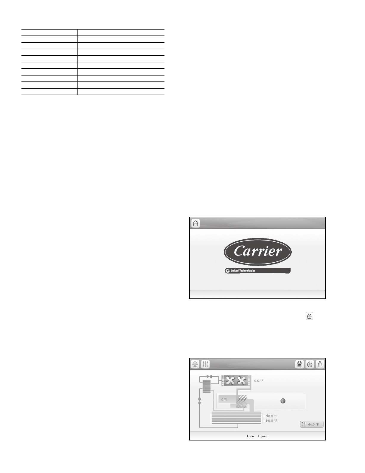
Table 1 — Unit Sizes
Fig. 1 — Welcome Screen
30XV
ACG-SR-10A2AA010
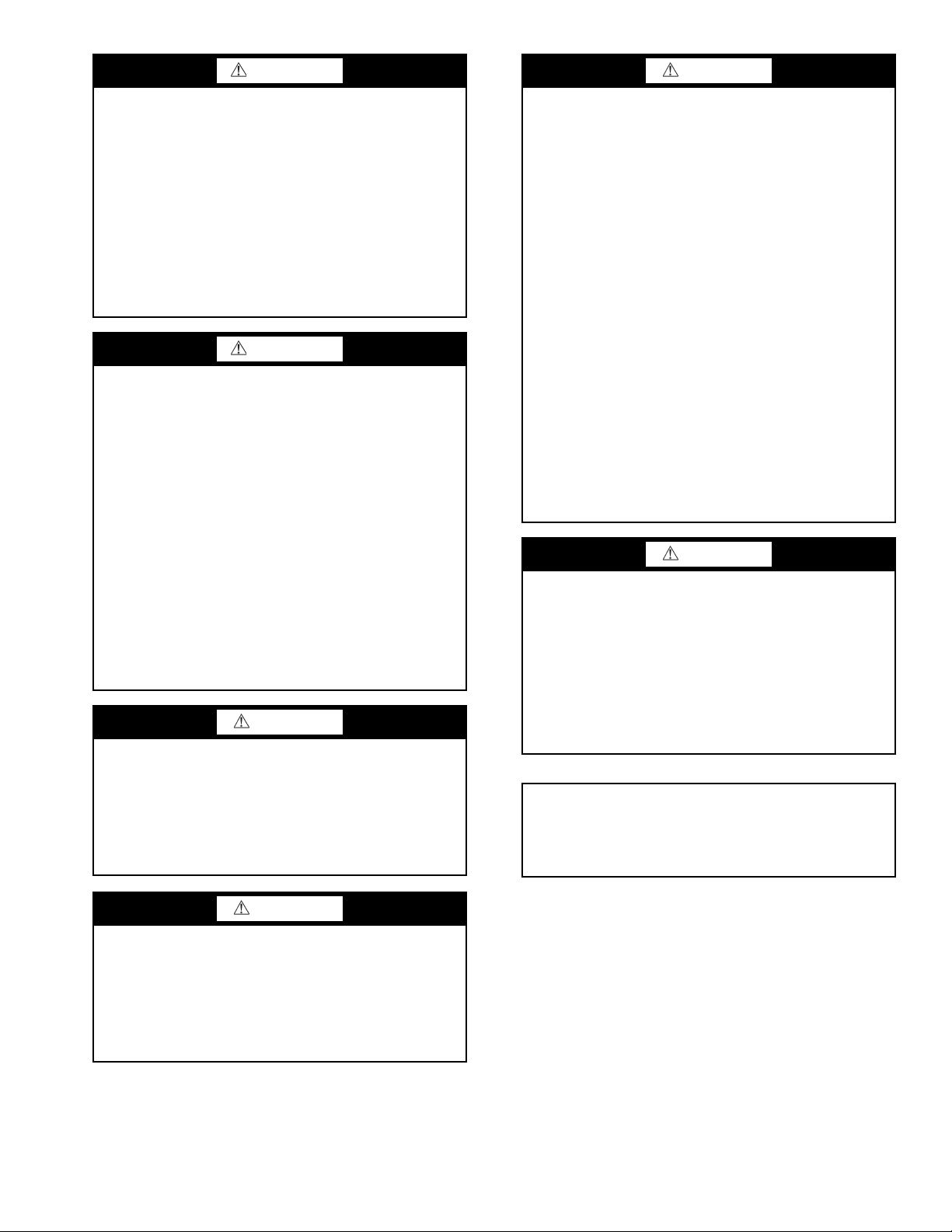
Fig. 2 — Home Screen
UNIT NOMINAL CAPACITY (TONS)
30XV140 140
30XV160 160
30XV180 180
30XV200 200
30XV225 225
30XV250 250
30XV275 275
30XV300 300
30XV325 325
Conventions Used in This Manual — The follow-
ing conventions for discussing configuration points for the
Touch Pilot display will be used in this manual.
The menu items are shown in this document as they appear
on the Touch Pilot display. A path name for each item will
show the user how to navigate through the Touch Pilot display
to reach the desired configuration. The arrow symbol () in
the path name represents touching the menu item on the screen
of the Touch Pilot
™
display. See Appendix A for a complete
list of Touch Pilot menu items and descriptions.
The CCN and BACnet* point names are shown in bold.
See Appendix B for a list of CCN points, and Appendix D for a
list of BACnet points.
Abbreviations Used in This Manual — The fol-
lowing abbreviations are used in this manual:
• ABV — Actuated ball valve
• AUX — Auxiliary (Board)
• BACnet — Building Automation and Controls Network.
Open Protocol for the controlled exchange of data between
two or more intelligent control devices or BMS. BACnet is
used over IP (Internet Protocol).
• CCN — Carrier Comfort Network
trolled exchange of data between two or more intelligent
PIC (Peripheral Interface Controller)/FID (Field Interface
Device) devices within the geographic confines of a single
building.
• CWFS — Chilled water flow switch
• DGT — Discharge gas temperature
• DPT — Discharge pressure
• EMM — Energy Management Module
• EWT — Entering water temperature
• HMI — Human Machine Interface
• LEN — Local Equipment Network. Protocol for the con-
trolled exchange of data between two or more intelligent
control devices within the geographic confines of a single
Carrier equipment installation.
• LPT — Liquid pressure transducer
• LWT — Leaving water temperature
• OAT — Outdoor air temperature
• SCT — Saturated condensing temperature
• SDT — Saturated discharge temperature
• SLT — Saturated liquid temperature
• SIOB — Standard Input/Output Board
• SM — System Manager
• SPT — Suction pressure transducer
• SST — Saturated suction temperature
®
. Protocol for the con-
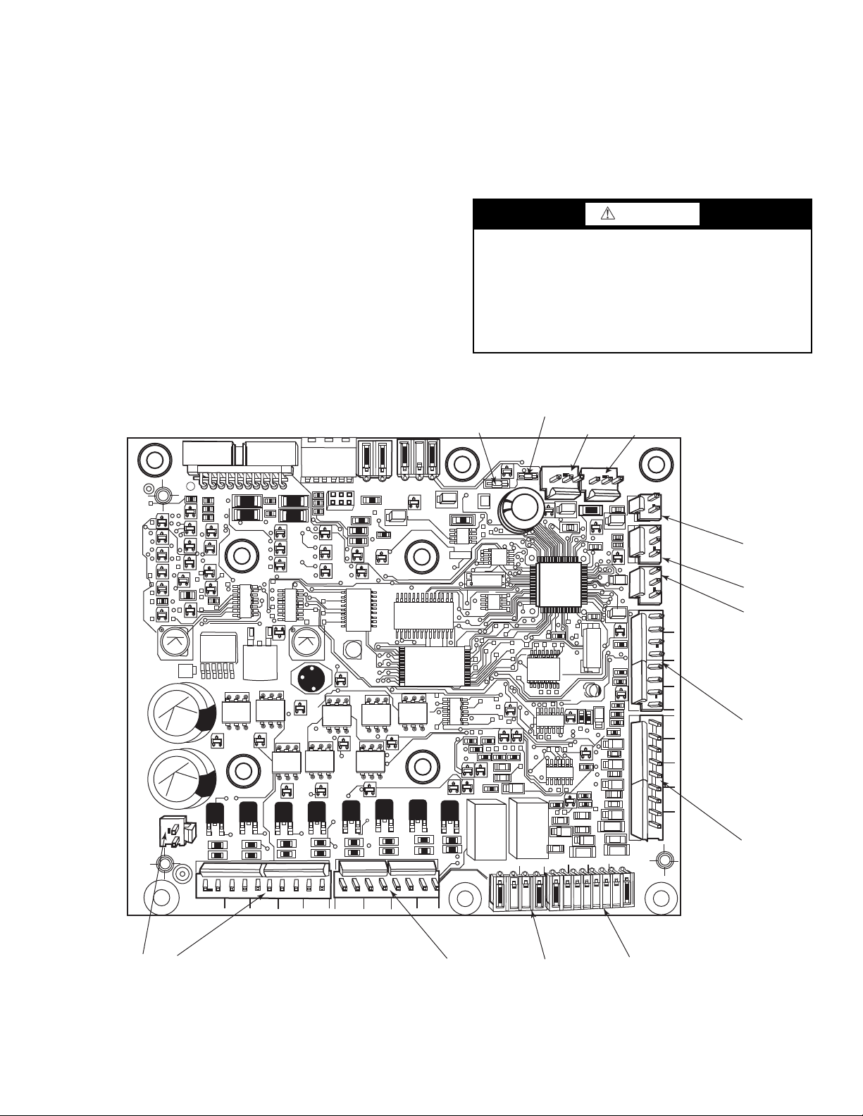
Touch Pilot Display — The Touch Pilot module is the
core of the control system. It contains the major portion of
operating software and controls the operation of the machine.
See Web and Network Interface section on page 11.
The Touch Pilot module continuously monitors input/output
channel information received from the SIOB and AUX boards.
The Touch Pilot receives inputs from status and feedback
switches, pressure transducers and thermistors. The Touch Pilot module, through the communications bus, also controls outputs on the SIOB and AUX boards. All inputs and outputs that
control the chiller are located on other boards. Information is
transmitted between modules via a 3-wire communication bus
or LEN (Local Equipment Network).
The CCN (Carrier Comfort Network
®
) bus is also supported.
Connections to both LEN and CCN buses are made at terminal board TB3 located within the control box enclosure to
the left of the Touch Pilot display.
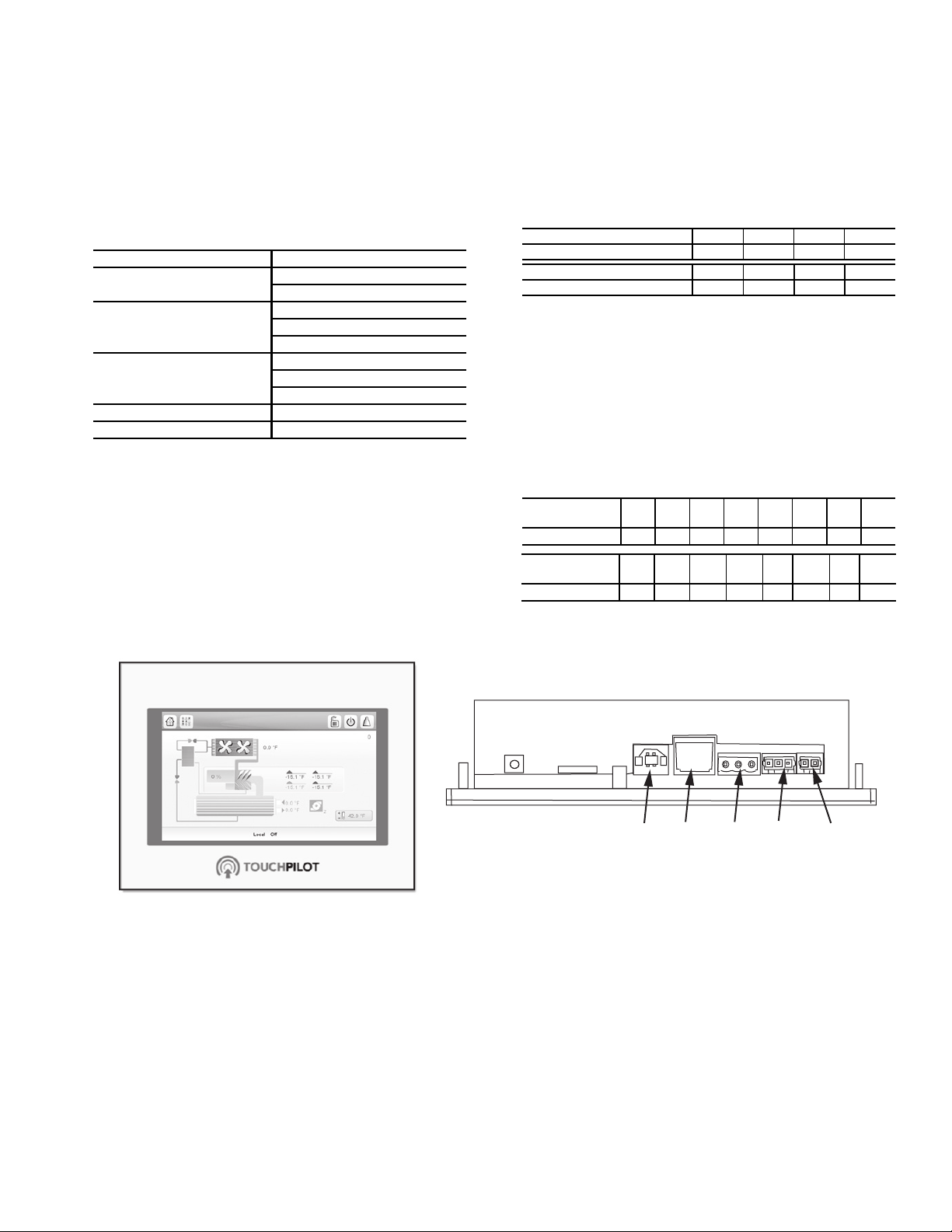
Touch Pilot Display User Interface — The Touch
Pilot display is the standard user interface on all 30XV
chillers with Greenspeed
a large 7-in. LCD (liquid crystal display) touch screen for
display and user configuration. A stylus is recommended for
use on the touch screen. The stylus is included with the unit.
WELCOME SCREEN — The Welcome screen is the first
screen shown after Touch Pilot starts. It displays the application
name as well as the current software version number. See Fig. 1.
NOTE: If a communication failure occurs, the Touch Pilot Settings button is displayed (see the "Touch Pilot Display Port
Connections" table on page 11 and the "Touch Pilot Display
Interface and Connectors" figure on page 11 ).
To exit the Welcome screen, press the Home button .
HOME SCREEN — The Home screen provides an overview
of system controls, allowing the user to monitor the vaporrefrigeration cycle. The screen indicates the current status of
the unit, giving information on the unit capacity, refrigerant
conditions, the status of the evaporator pumps, the active set
point, and other information. See Fig. 2.
®
intelligence. The display includes
CONTROLS
The 30XV air-cooled liquid chillers contain the Touch Pilot™
electronic control system that controls and monitors all operations of the chiller. The control system is composed of several
components as listed in the following sections. All machines
have a Touch Pilot module, Standard Input/Output (SIOB)
boards, Emergency On/Off switch, and an Enable-Off-Remote
Contact switch. Table 2 lists power schematics by unit size.
*BACnet is a registered trademark of ASHRAE (American Society of
Heating, Refrigerating, and Air-Conditioning Engineers).
4

Table 2 — Control and Power Drawings
UNIT DESCRIPTION LOCATION
Typical Field Connections Wiring Schematic Fig. 70, page 117
Power Wiring Schematic (Std) Fig. 71, page 118
30XV140
30XV160
30XV180
30XV200
30XV225
30XV250
30XV275
30XV300
30XV325
Power Wiring Schematic (Mid) Fig. 73, page 120
Power Wiring Schematic (High)
Communication Wiring Fig. 78, page 125
Control Wiring Schematics Fig. 79-81, pages 126-128
Typical Field Connections Wiring Schematic Fig. 70, page 117
Power Wiring Schematic (Std) Fig. 71, page 118
Power Wiring Schematic (Mid)
Power Wiring Schematic (High)
Communication Wiring Fig. 78, page 125
Control Wiring Schematics Fig. 79-81, pages 126-128
Typical Field Connections Wiring Schematic Fig. 70, page 117
Power Wiring Schematic (Std) Fig. 71, page 118
Power Wiring Schematic (Mid)
Power Wiring Schematic (High)
Communication Wiring Fig. 78, page 125
Control Wiring Schematics Fig. 79-81, pages 126-128
Typical Field Connections Wiring Schematic Fig. 70, page 117
Power Wiring Schematic (Std) Fig. 71, page 118
Power Wiring Schematic (Mid)
Power Wiring Schematic (High)
Communication Wiring Fig. 78, page 125
Control Wiring Schematics Fig. 79-81, pages 126-128
Typical Field Connections Wiring Schematic Fig. 70, page 117
Power Wiring Schematic (Std) Fig. 71, page 118
Power Wiring Schematic (Mid) Fig. 73, page 120
Power Wiring Schematic (High)
Communication Wiring Fig. 78, page 125
Control Wiring Schematics Fig. 79-81, pages 126-128
Typical Field Connections Wiring Schematic Fig. 70, page 117
Power Wiring Schematic (Std) Fig. 71, page 118
Power Wiring Schematic (Mid) Fig. 73, page 120
Power Wiring Schematic (High)
Communication Wiring Fig. 78, page 125
Control Wiring Schematics Fig. 79-81, pages 126-128
Typical Field Connections Wiring Schematic Fig. 70, page 117
Power Wiring Schematic (Std) Fig. 71, page 118
Power Wiring Schematic (Mid) Fig. 73, page 120
Power Wiring Schematic (High)
Communication Wiring Fig. 78, page 125
Control Wiring Schematics Fig. 79-81, pages 126-128
Typical Field Connections Wiring Schematic Fig. 70, page 117
Power Wiring Schematic (Std) Fig. 72, page 119
Power Wiring Schematic (Mid)
Power Wiring Schematic (High)
Communication Wiring Fig. 78, page 125
Control Wiring Schematics Fig. 79-81, pages 126-128
Typical Field Connections Wiring Schematic Fig. 70, page 117
Power Wiring Schematic (Std) Fig. 72, page 119
Power Wiring Schematic (Mid)
Power Wiring Schematic (High)
Communication Wiring Fig. 78, page 125
Control Wiring Schematics Fig. 79-81, pages 126-128
Fig. 74, page 121
Fig. 75, page 122
Fig. 73, page 120
Fig. 75, page 122
Fig. 74, page 121
Fig. 75, page 122
Fig. 73, page 120
Fig. 75, page 122
Fig. 74, page 121
Fig. 75, page 122
Fig. 73, page 120
Fig. 75, page 122
Fig. 74, page 121
Fig. 75, page 122
Fig. 76, page 123
Fig. 77, page 124
Fig. 76, page 123
Fig. 77, page 124
Fig. 76, page 123
Fig. 77, page 124
Fig. 76, page 123
Fig. 77, page 124
Fig. 76, page 123
Fig. 77, page 124
Fig. 76, page 123
Fig. 77, page 124
Fig. 76, page 123
Fig. 77, page 124
5
To display the SDT and SST for each circuit select the i. See
LEGEND
1—Unit capacity percentage
2—Unit status
3—Evaporator inlet and outlet water temperature
4—Pump status (if configured)
5—Active setpoint
6—SDT/SST (Ckt. A on LEFT, Ckt. B on RIGHT)
7—Outdoor air temperature
Fig. 3 — Home Screen with SDT/SST
1
2
3 4
5
6
7
Fig. 3.
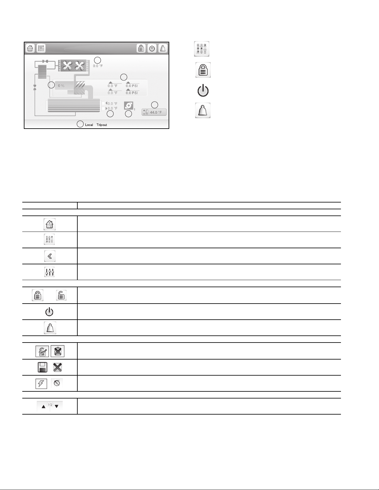
Table 3 — Screen Buttons
BUTTON FUNCTION
TOP LEFT PANEL — GENERAL NAVIGATION
The following buttons appear on the top panel of the home
screen. See Table 3 for more general screen buttons.
Main Menu — Press the Main Menu button to access
all unit functions. See Main Menu Screen on page 8
for details.
Log In — Press to enter passwords and select language or change the system of measurement. See
page 8 for login details.
Start/Stop — Press to access the chiller operating
modes menu. See page 20 for details on available
operating modes.
Alarm — The alarm icon turns solid or blinks red
when a fault is detected. See page 100 for details on
system alarms and alerts.
STATUS MESSAGE BOX — Messages may be displayed
in the status bar at the bottom of the screen relevant to the current user action. See Table 4.
Home button: Goes back to the home screen. Button is disabled at power up, until the initialization is complete.
Main Menu button: Goes to the Main Menu screen from the Home screen. Allows access to unit menus and parameters.
See page 8.
Back button: Goes to previous screen.
HMI Settings: Goes to the Touch Pilot settings. Button appears in the Welcome screen only when a communication failure occurs, to provide the user a chance to fix the problem.
TOP RIGHT PANEL — SPECIAL NAVIGATION
and
BOTTOM LEFT PANEL — ACTIONS SPECIFIC TO CURRENT SCREEN OPERATION
BOTTOM RIGHT PANEL — SCROLLING INSIDE CURRENT SCREEN
Login button: Goes to the User Login screen, where the user can select a display language and system of measurement,
and log in. See page 8. Icon shows a closed lock when the user is not logged in, and an opened lock when the user is
logged in.
Start / Stop button: Goes to the chiller start / stop screen. The icon can be gray, green, or blinking between gray and
green. See the Machine Control Methods section on page 20.
Alarm button: Goes to the alarm menu screen.The icon can be gray, red, or blinking between gray and red. See the
Alarms and Alerts section on page 100.
User Login screen: Login / Logout. Login button (green check mark) validates the currently entered user level (Basic,
User, Service Or Factory), and jumps back to the previous screen. Logout button (red X) resets the user level and jumps
to the Welcome screen.
Save/Cancel: Save button (disc icon) confirms changes. Cancel (red X) discards changes.
Force Screen: Set Force/Remove Force. Set Force button sends a CCN Force command to the point. Remove Force
(AUTO) button sends a CCN Auto command to the point.
Up and Down arrows: Scroll within screen content. A page indicator shows what page is being viewed, and the total
number of pages.
6

Table 4 — Status Messages
MESSAGE STATUS
COMMUNICATION FAILURE! Equipment controller did not respond while reading the table content.
ACCESS DENIED!
LIMIT EXCEEDED! The value entered exceeds the parameter limit.
COMMAND ACCEPTED Force or Auto command was accepted by the Equipment Controller.
HIGHER FORCE IN EFFECT! Equipment controller rejects Force or Auto command.
Save changes? Modifications have been made. The exit must be confirmed by pressing Save or Cancel.
Invalid password! Entered password is not valid
Log level = basic Entered password is 0 = basic, login is allowed
Log level = User Entered password corresponds to the User password, login is allowed
Log level = Service Entered password corresponds to the Service password, login is allowed
Log level = Factory Entered password corresponds to the Factory password, login is allowed
PLEASE LOGIN Login required before accessing start/stop function
Select Machine Mode Default prompt when entering the Start/Stop screen.
Machine Status Application status message (see somewhere else)
Loading Data … Trend Manager is not ready yet.
TRENDING FIRMWARE MODULE ERROR!
BACNET FIRMWARE MODULE NOT FOUND!
Equipment controller denies access to one of the tables. See Touch Pilot Login and
Display Setup, page 8.
Trend Manager detected a problem during its initialization sequence (file access or file
content problem) and cannot display Trend/Log data.
BACNet module is not responding (its web server is not functional, or the whole module
failed to start).
Too Many users connected! Please try again later … Maximum of 2 concurrent web server connections allowed.
Application Firmware must be downloaded!
The software detected a conflict between the version of the web server web pages, and
the HMI application firmware.
7
™
LEGEND
1—Arrows indicate selected language
2—Login button (confirm changes)
3—Logout button (cancel changes)
4—System of measurement selection
5—Password dialog box
Fig. 4 — User Login Screen
1
2
3 5
4
a30-5914
PRESS TO NAVIGATE
THROUGH MENUS
OR TABLES
Fig. 5 — Main Menu
Fig. 6 — General Parameters, Page 1
TOUCH PILOT
LOGIN AND DISPLAY SETUP —
Certain control functions and navigation menus are password
protected. There are multiple levels of user access on the
Touch Pilot display, each with independent password protection:
• Basic — At initial start-up and after a timeout period, the
access type defaults to All. In this mode the user can view
system operating conditions, and select the set point only.
• User — The User access level authorizes access to mod-
ify the Setpoint Table and some Configuration Menu
parameters, as well as access to all menus accessible
with the Basic mode. The default password for User
level access is 11. To change the User access password,
go to Main Menu Configuration Menu User Configuration, then enter the new password and press the
Save button.
• Service — The Service access level authorizes access to
all menus and parameters needed for operation and service
of the machine, including Quick Test and Maintenance
Menus as well as additional Configuration Menus. The
default password for Service level access is 88. To change
the Service access password, go to Main Menu Configuration Menu Service Parameters, then scroll to the
password entry area. Enter the new password and press the
Save button.
• Factory — The Factory access level authorizes access to
all menus and parameters for the unit, including factory
settings. The default password for Factory level access is
113. To change the Factory access password, go to Main
Menu Configuration Menu Factory Menu, then
scroll to the password entry area. Enter the new password and press the Save button.
To log in to the Touch Pilot display, press the Login button
on the Main Menu or the Home screen and input the
required password on the User Login screen. Then press the
Login button on the User Login screen. See Fig. 4.
Changing the Units of Measurement
— The User Login
Screen (Fig. 4) offers 2 choices for units of measurement: US
Imperial or Metric. The factory default is US Imperial. To
change the measurement system, select the appropriate system
on the User Login screen.
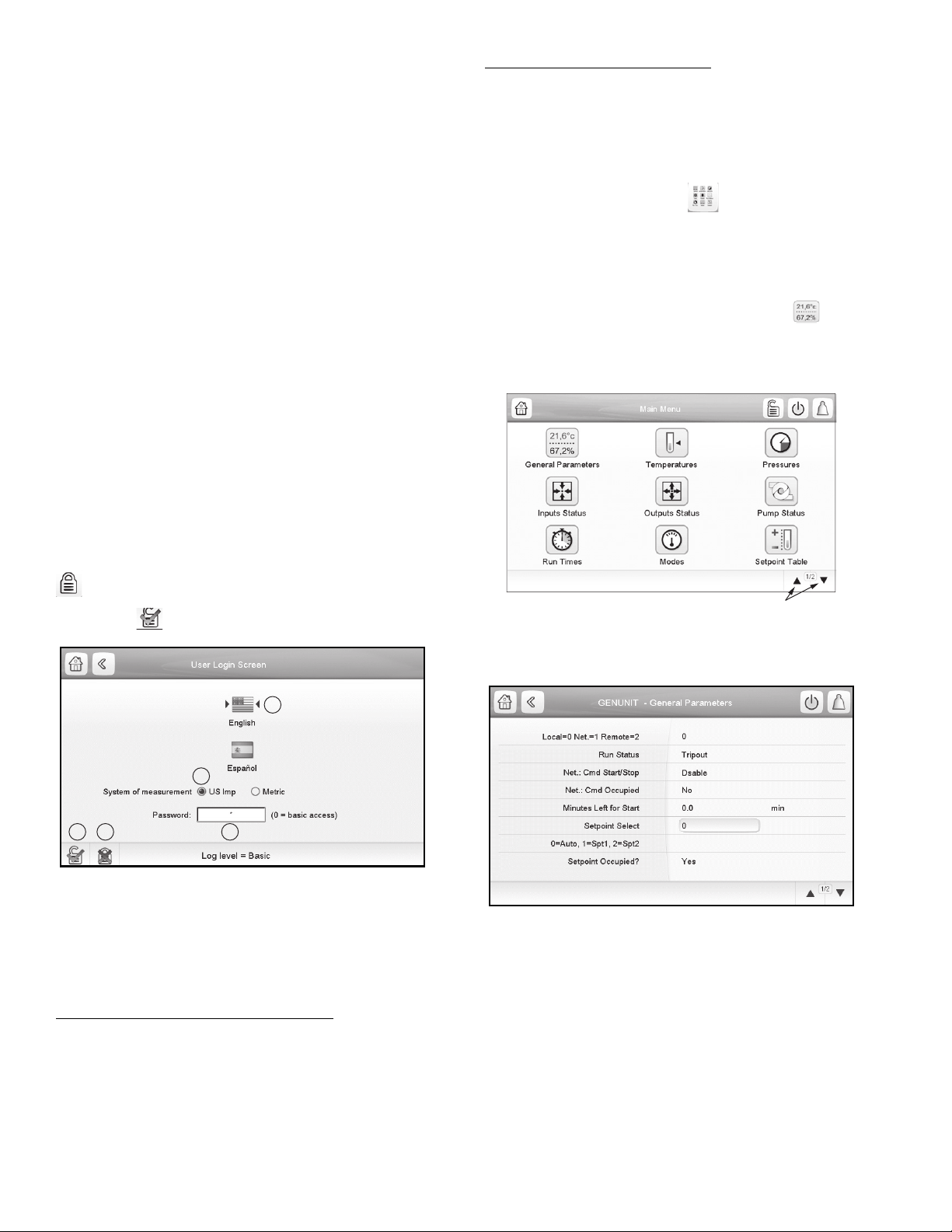
MAIN MENU SCREEN — The Main Menu provides access
to the main control parameters, including general parameters,
temperatures and pressures, inputs and outputs status, and others. Press the Main Menu button on the Home screen to
access the Main Menu.
Figure 5 shows the first page of the Main Menu. To navigate through the pages, press the arrows at the lower right corner of the screen.
To view or modify system parameters, press the appropriate
icon on the Main Menu. For example, to access the General Parameters table, press the General Parameters button .
Figure 6 shows the first page of the General Parameters table. Use the arrows at the bottom right corner to navigate the
General Parameters table.
Changing the Touch Pilot Display Language
Login Screen (Fig. 4) offers 2 language selections for the
Touch Pilot Display: English or Spanish. The factory default
language is English. To change the display language, simply
select the language icon on the User Login screen.
— The User
Points that can be changed with the current level of user access are outlined by a box. For example, to modify the set point
parameter, select the current set point as shown in Fig. 6 and
enter the desired parameter.
The data entry screen will be displayed (Fig. 7). Use the
graphic “keyboard” to modify the parameter, then press OK to
save or EXIT to cancel the modifications.
8
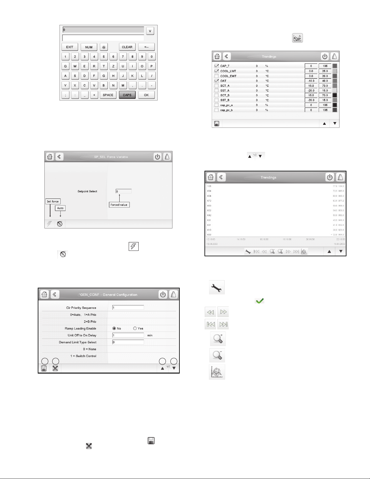
Since Setpoint Select (Fig. 6) is a forcible point (the op-
a30-5911
Fig. 7 — Data Entry Screen
Fig. 8 — Force Variable Screen
Fig. 9 — General Configuration, Page 1
LEGEND
1— Save
2— Cancel
3— Previous page
4— Next page
1 2 3 4
a30-5908
Fig. 10 — Trendings Screen, Page 1
Fig. 11 — Trendings Screen, Page 2
erator is able to manually override the auto function), the
Force Variable screen will be displayed. See Fig. 8. The
Force Variable screen provides the option to override the
current operation of the unit.
TRENDINGS SCREEN — The Trendings screen allows for
easy monitoring of parameters selected by the user. To access
the Trendings screen, select Trendings on the Main Menu.
See Fig. 10.
Select the parameters to be displayed by selecting the box to
the left of the parameter name, then press save. Press the up/
down page buttons to see the graph showing the performance of the unit during a selected period of time. See Fig. 11.
Enter the forced value, then press to set the forced
point or to remove it (return to Auto).
GENERAL CONFIGURATION TABLE — This table con-
tains configuration settings for the unit. Select Main Menu
Configuration Menu General Configuration to access the table (Fig. 9).
Press the field corresponding to the parameter to be modified and make the necessary changes. When all necessary
changes have been made, press the Save button to confirm
or the Cancel button to cancel changes. For a complete list
of general parameters, see Appendix A.
a30-5909
Use the following buttons to adjust the Trendings display:
Press to adjust time and date settings for the display. See Fig. 11. Select the time/date boxes and
use graphic keyboard to modify time/date; then
select the to save your entries.
Navigate across the time line.
Go to beginning or end of selected period.
Zoom in to magnify the view.
Zoom out to expand the viewed area.
Refresh (reload) data.
MENU ARCHITECTURE — See Fig. 12-14 for Touch Pilot™ menu structure. The options displayed depend on the user’s access level as shown in the figures. The user can navigate
through the Touch Pilot display screens by selecting the buttons that appear on the screen. When a button is selected, either
a submenu or a list of parameters and values will be shown.
If the list of point names and values are shown, the top line
of the display is the table name. Selecting an item will cause a
Point Data dialog box to appear. For a complete list of tables
and points with display names and CCN point names, see Appendix A.
9
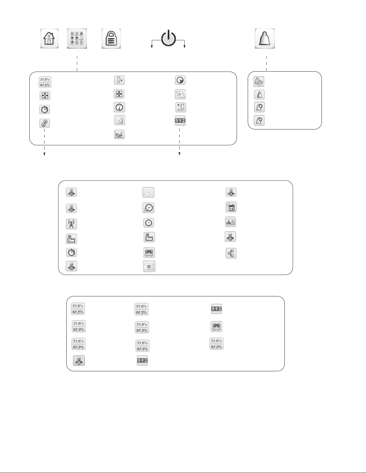
Fig. 12 — Main Menu and Alarm Menu Structure
HOME
MAIN MENU LOG IN/LOG OUT CONFIRM STOP CHOOSE OPERATING MODE ALARM MENU
GENERAL PARAMETERS
CONFIGURATION MENU
1
1
1
2
TEMPERATURES
OUTPUTS STAT US
MODES
QUICK TEST TABLE
TRENDINGS
1
1
1
1
3
PRESSURES
PUMPS STAT US
SETPOINT TABLE
MAINTENANCE MENU
1
1
2
3
INPUTS STAT US
RUN TIMES
1
1
1
2
RESET ALARMS
CURRENT ALARMS
ALARM HISTORIC
MAJOR ALARM HISTORIC
TO CONFIGURATION MENU
TO MAINTENANCE MENU
a30-5904
Fig. 13 — Configuration Menu Structure
GENERAL CONFIGURATION
2
RESET CONFIGURATION
2
4
BROADCAST MENU
2
FACTORY PARAMETERS
UPDATE RUNNING HOUR
3
4
COMPRESSOR ENABLE
3
PUMP CONFIGURATION
2
SCHEDULE MENU
2
DATE/TIME CONFIGURATION
2
FACTORY2 PARAMETERS
MASTER SLAVE CONFIG
3
EMAIL CONFIGURATION
3
USER CONFIGURATION
HOLIDAY MENU
CONTROL IDENTIFICATION
SERVICE PARAMETERS
BACNET PARAMETERS
3
3
2
2
2
a30-5905
Fig. 14 — Maintenance Menu Structure
CAPACITY CONTROL
EXV CONTROL
EXV ECO. CONTROL
VLT DRIVE MAINTENANCE
CONTROL LIMITS
FAN CONTROL
FAN DRIVE ADDRESSING
LAST POWER ON RESET
MASTER SLAVE CONTROL
FAN DRIVE MAINTENANCE
3
3
3
3
3
3
3
3
3
3
a30-5906
TROUBLESHOOT
3
LEGEND — FIG. 12-14
1—All (no password required)
2—User access required (default password = 11)
3—Service access required (default password = 88)
4—Factory access required (default password = 113)
NOTE: For more information about password access, see the section Touch Pilot
™
Login and Display Setup on page 8.
10
SETTING TIME AND DATE — The date and time for the
Fig. 15 — Touch Pilot Display Interface and Connectors
controls can be set by opening the Main Menu Configuration
Menu Date/Time Configuration. The date, time, day of the
week, and daylight saving time option can be set on this screen.
WEB AND NETWORK INTERFACE — The Touch Pilot
control can be configured to allow access via a standard, javaenabled web browser or over a network. See Appendix H for
detailed information on setting up and accessing the Touch Pilot via the web or network interface. See Table 5 for port connections. See Fig. 15 for interface and connectors.
Table 5 — Touch Pilot Display Port Connections
CONNECTOR FUNCTION
X5 (Power)
X4 (LEN)
X3 (CCN)
X2 (Ethernet) —
X1 (USB) —
24 VAC +
24 VAC –
RS485 Port (D+)
RS485 Port (GND)
RS485 Port (D–)
RS485 Port (D+)
RS485 Port (GND)
RS485 Port (D–)
Input/Output (SIOB) Boards — There are two
SIOB (Standard Input/Output Boards) boards for each unit,
SIOB-A (address 49) for Circuit A and SIOB-B (address
50) for circuit B. See Fig. 16. The board receives inputs
from thermistors, transducers, demand limit switch, dual set
point switch, remote-on-off switch, chilled water flow
switch, oil level switch, pump interlock contact, compressor
VFD enable contact, and evaporator heater current sensing
switch, and provides output control to expansion valves, oil
and VI solenoids, evaporator heater contactor, isolation
valves, oil heater relays, customer supplied pump relays,
compressor VFD enable relays, and customer-supplied
alarm and running relays. Information is transmitted
between the SIOB boards and the Touch Pilot module via a
3-wire communication bus or LEN (Local Equipment Network). Connections for the LEN bus are J12 and J13. Each
SIOB board has a 4-position DIP switch bank used for
addressing of the board. SIOB-A is at address 49 and SIOBB is at address 50. See below for SIOB board DIP switch
settings. See Tables 6 and 7 for a list of inputs and outputs
for the two SIOB boards.
SIOB-A DIP Switch 1 2 3 4
Position: OFF OFF OFF OFF
SIOB-B DIP Switch 1 2 3 4
Position: ON OFF OFF OFF
Auxiliary (AUX) Boards — Two AUX boards, AUX
Board A (address 84) and AUX Board B (address 85), are
installed in each unit. Each of the AUX boards has a set of
jumpers, JP1 and JP2, which must be placed as shown in
Fig. 17. The AUX boards respond to commands from the
Touch Pilot
results of the channels they monitor via the Local Equipment Network (LEN). See below for AUX board A and B
DIP switch settings. See Tables 8 and 9 for a list of inputs
and outputs for the AUX boards.
AUX BOARD A
DIP SWITCH
Address: ON ON OFF OFF ON OFF ON OFF
AUX BOARD B
DIP SWITCH
Address: OFF OFF ON OFF ON OFF ON OFF
™
module and send the Touch Pilot module the
12345678
1 2 3 45678
X1 - USB CONNECTOR
X2 - ETHERNET CONNECTOR
X3 - CCN CONNECTOR
X4 - LEN CONNECTOR
TOUCH PILOT DISPLAY INTERFACE
X5 - POWER SUPPLY CONNECTOR (24 VAC)
11
X2X1
TOUCH PILOT BOTTOM VIEW
X5X4X3
a30-5895
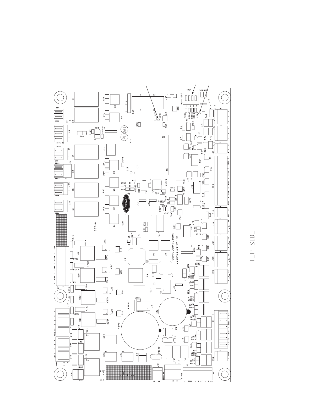
Fig. 16 — SIOB (Standard Input/Output Board)
a30-5864
DIP
SWITCH
GREEN LED - LEN
(Local Equipment Network)
RED LED - STAT US
12
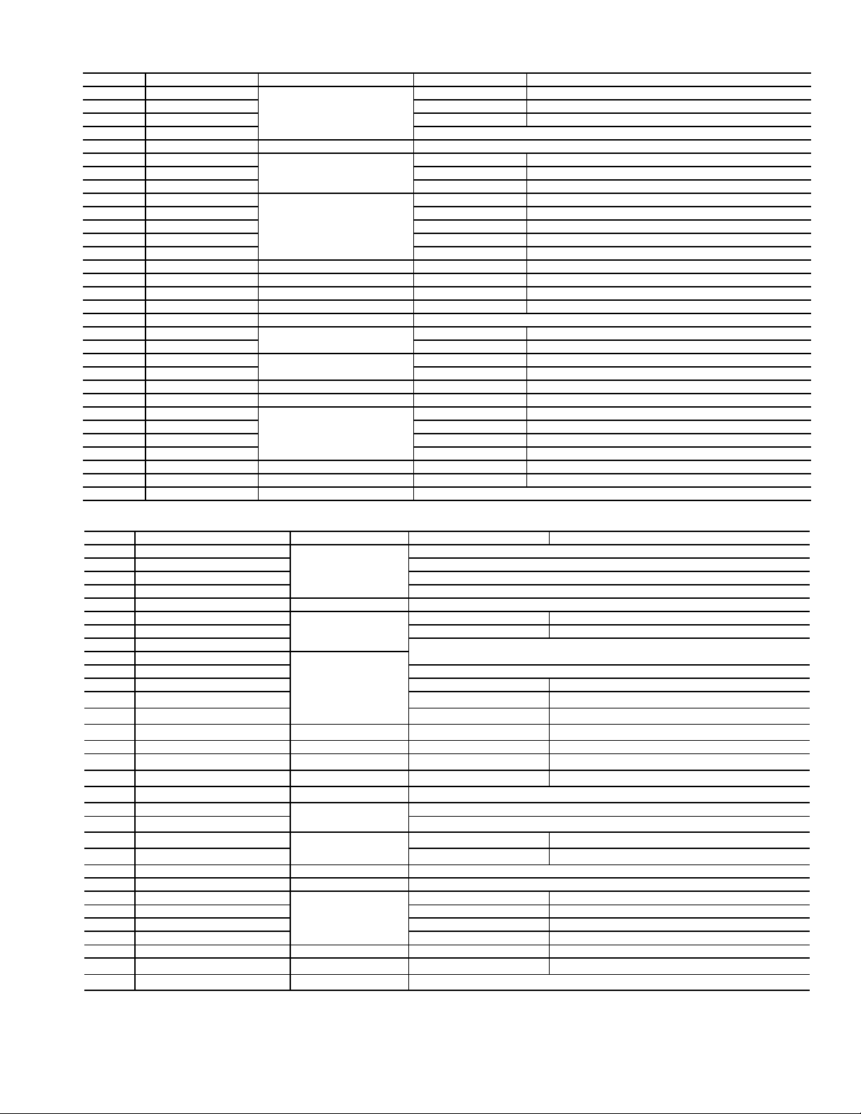
Table 6 — SIOB-A Inputs and Outputs
ITEM IN/OUT TYPE BOARD CONNECTOR CCN POINT DESCRIPTION
DI-01 Dry contact
DI-02 Dry contact SETP_SW Dual Setpoint Switch
DI-03 Dry contact LIM_SW1 Demand Limit Switch 1 OnOff
DI-04 Dry contact — Not Used —
DI-05 Dry contact J34 — Not Used —
DI-06 Dry contact
DI-07 Dry contact FLOW_SW Chilled Water Flow Switch (CWFS)
DI-08 Dry contact HEATR_SW Cooler Heater Current Sensing Rly Feedback
AI-01 Temp (5000 )
AI-02 Temp (5000 ) COOL_LWT Cooler Leaving Water Temperature
AI-03 Temp (5000 ) OAT Outdoor Air Temperature
AI-04 Temp (5000 ) CP_TMP_A Compressor A motor temperature
AI-05 Temp (5000 ) ECO_T_A Economizer Temperature Circuit A
AI-06 Pressure J11 DP_A Discharge Pressure Circuit A
AI-07 Pressure J19 SP_A Suction Pressure Circuit A
AI-08 Pressure J20 ECO_P_A Economizer Pressure Circuit A
AI-09 Pressure J21 OP_A Oil Pressure Circuit A
AI-10 4 to 20 mA J9 — Not Used —
DO-01 Relay output
DO-02 Relay output CPUMP_2 Customer Pump Relay #2
DO-03 Relay output
DO-04 Relay output VFD_EN_A VFD Enable Output Circuit A
DO-05 Relay contact J23 ALARM Alarm Relay
DO-06 Relay contact J22 RUNNING Running Relay
DO-07 Triac
DO-08 Triac C_HEATER Cooler Heater Contactor
DO-09 Triac VI_A VI Solenoid Control Compressor Circuit A
DO-10 Triac ISO_POS_A Isolation Valve Relay Circuit A
STPR1 Stepper motor J17 EXV_A EXV-A
STPR2 Stepper motor J18 ECO_A ECEXV-A
AO-01 0 to 10 VDC J10 — Not Used —
J1
J3
J25
J2
J6
J7
ONOFF_ SW Remote On-Off Switch (SW1)
OIL_L_A Oil Level Switch Circuit A
COOL_EWT Cooler Entering Water Temperature
CPUMP_1 Customer Pump Relay #1
OIL_HT_A Oil Heater Contactor Circuit A
OIL_SL_A Oil Solenoid Circuit A
Table 7 — SIOB-B Inputs and Outputs
ITEM IN/OUT TYPE BOARD CONNECTOR CCN POINT DESCRIPTION
DI-01 Dry contact
DI-02 Dry contact — Not Used —
DI-03 Dry contact — Not Used —
DI-04 Dry contact — Not Used —
DI-05 Dry contact J34 — Not Used —
DI-06 Dry contact
DI-07 Dry contact FLOW_SWB Customer Supplied Pump Interlock Relay
DI-08 Dry contact — Not Used —
AI-01 Temp (5000 )
AI-02 Temp (5000 ) — Not Used —
AI-03 Temp (5000 ) CHWSTEMP Dual chiller temperature (accessory)
AI-04 Temp (5000 ) CP_TMP_B Compressor motor temperature Circuit B
AI-05 Temp (5000 ) ECO_T_B Economizer temperature Circuit B
AI-06 Pressure
AI-07 Pressure J19 SP_B Suction pressure Circuit B
AI-08 Pressure
AI-09 Pressure
AI-10 4 to 20 mA
DO-01 Relay output
DO-02 Relay output — Not Used —
DO-03 Relay output
DO-04 Relay output VFD_EN_B VFD enable output Circuit B
DO-05 Relay contact J23 — Not Used —
DO-06 Relay contact J22 — Not Used —
DO-07 Triac
DO-08 Triac BOX_HTR Control box heater
DO-09 Triac VI_B Vi solenoid control compressor Circuit B
DO-10 Triac ISO_POS_B Isolation valve relay Circuit B
STPR1 Stepper motor J17 EXV_B EXV-B
STPR2 Stepper motor
AO-01 0 to 10 VDC
J1
J3
J25
J11
J20
J21
J9
J2
J6
J7
J18
J10
OIL_L_B Oil level Circuit B
DP_B Discharge pressure Circuit B
ECO_P_B Economizer pressure Circuit B
OP_B Oil pressure Circuit B
OIL_HT_B Oil heater contactor Circuit B
OIL_SL_B Oil solenoid Circuit B
ECO_B ECEXV-B
LEGEND
AI — Analog Input
AO — Analog Output
DI — Discrete Input
DO — Discrete Output
STPR — Stepper Motor Output
— Not Used —
— Not Used —
— Not Used —
— Not Used —
— Not Used —
13
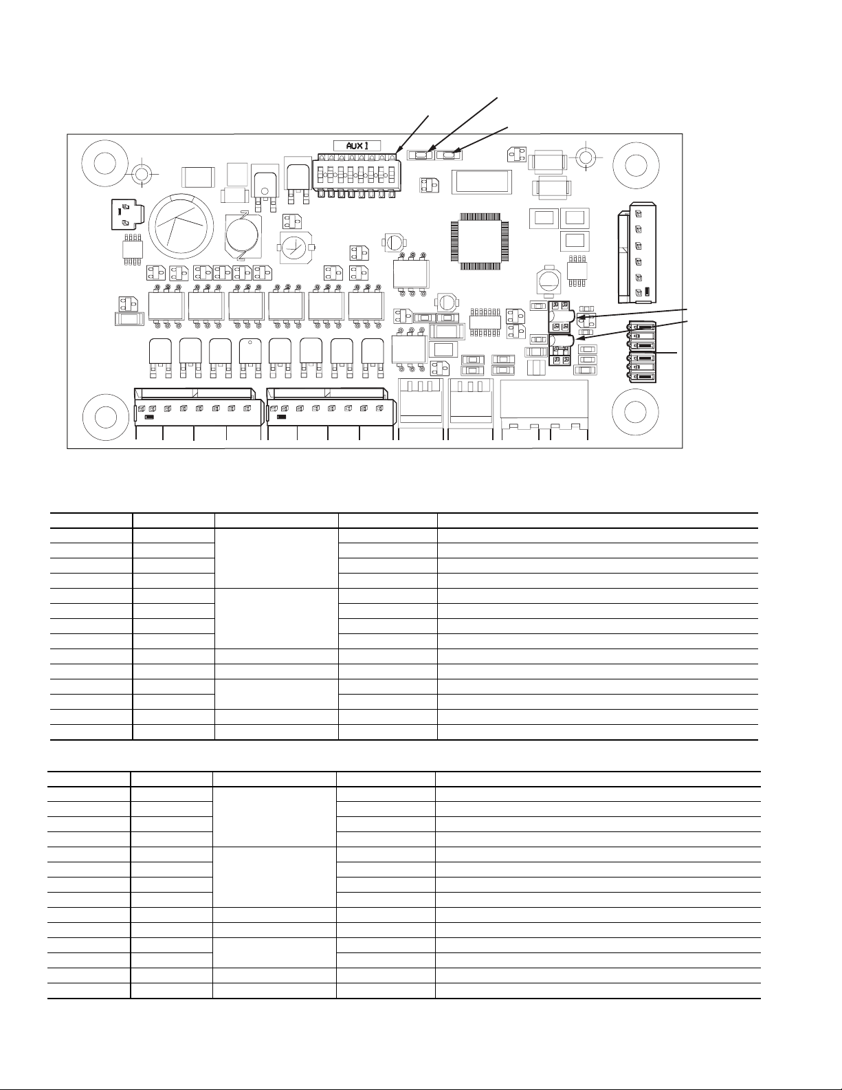
Table 8 — AUX Board A Inputs and Outputs
Fig. 17 — AUX Board
1
2
3
4
5
6
7
8
ON
100K
100K
100K
CH1
CH2 CH3
CH4 CH5 CH6 CH7 CH8
TR1 TR2 TR3 TR4 TR5 TR6 TR7 TR8
STAT US SIO (LEN)
24 VAC
CH13 CH14
J9
J1
CH9
CH10
CH11
CH12
JP2
C61
CH13
D12
JP1
L3
L5
U21
L2
D6
D5
Q5
Y1
D7
D8
S1
D3
U1
Q1
U5
U6
U7
U8
U9
Q10
Q11
U10
J4
J3
J2
U4
U2
Q12
Q60
3 2 1
– G +
3 2 1
– G +
DIP SWITCH
J5
J6
J7 J8
RED LED - STAT US
GREEN LED - LEN
(Local Equipment Network)
JUMPER JP2
JUMPER JP1
CHANNEL IN/OUT TYPE BOARD CONNECTOR CCN POINT DESCRIPTION (SEE NOTE 1)
CH 1 DO
CH 2 DO FC2_A Fan A Stage 2
CH 3 DO FC3_A Fan A Stage 3
J2
CH 4 DO FC4_A Fan A Stage 4
CH 5 DO
CH 6 DO FC6_A Fan A Stage 6
CH 7 DO FC7_A Fan A Stage 7
J3
CH 8 DO FC8_A Fan A Stage 8
CH 9 AO J4 CAPT010A % Capacity Circuit A (0-10Vdc)
CH 10 AO J5 — Not Used
CH 11 AI
CH 12 AI SUCT_A Suction Gas Temperature Circuit A
J6
CH 13 AI J7 LIQ_T_A Liquid Temperature Circuit A
CH 14 AI J8 LIQ_P_A Liquid Pressure Circuit A
Table 9 — AUX Board B Inputs and Outputs
CHANNEL IN/OUT TYPE BOARD CONNECTOR CCN POINT DESCRIPTION (SEE NOTE 1)
CH 1 DO
CH 2 DO FC2_B Fan B Stage 2
CH 3 DO FC3_B Fan B Stage 3
CH 4 DO FC4_B Fan B Stage 4
CH 5 DO
CH 6 DO FC6_B Fan B Stage 6
CH 7 DO FC7_B Fan B Stage 7
CH 8 DO FC8_B Fan B Stage 8
CH 9 AO J4 CAPT010B % Capacity Circuit B (0-10Vdc)
CH 10 AO J5 — Not Used
CH 11 AI
CH 12 AI SUCT_B Suction Gas Temperature Circuit B
CH 13 AI J7 LIQ_T_B Liquid Temperature Circuit B
CH 14 AI J8 LIQ_P_B Liquid Pressure Circuit B
Note: Fan A and B stage outputs are only used on STANDARD TIER
units, identified by the 10th position in the model number.
J2
J3
J6
FC1_A Fan A Stage 1
FC5_A Fan A Stage 5
DGT_A Discharge Gas Temperature Circuit A
FC1_B Fan B Stage 1
FC5_B Fan B Stage 5
DGT_B Discharge Gas Temperature Circuit B
14
Enable-Off-Remote Contact Switch (SW1) —
Fig. 18 — Energy Management Module
221
221
221
221
100K
100K
100K
100K
100K
CH
17
CH
17
CH
16
CH
CH
18
CH
19
CH
20
CH
22
CH
21
CH
23
24 VAC
12 11
CH
11b
CH
12
CH
13
CH
14
CH
15
CH
1
CH
2
CH
3
CH
4
CH 5
CH 6
CH 7
SIO LEN
+ G -
+ G -
SIO LEN
J8
J7B
J7A
J6
J5
J4 J3 J2B
J2A
J1
CH
24CH25
CH
8
CH
9
CH
10
CH
11a
J9A
J9B
RED LED - STAT US
GREEN LED - LEN
(Local Equipment Network)
The position of the Enable/Off/Remote contact switch is
ignored except when the “remote mode” control type is
selected. Refer to the Machine Control Methods section on
page 20 for more details. A selection for Machine Control
Method must also be made along with the correct position of
the Enable-Off-Remote Contact Switch. This switch is
installed in all units. It is a 3-position switch used to control the
chiller. When switched to the Enable position, the chiller will
be under its own control. When switched to the Off position,
the chiller will shut down. When switched to the Remote Contact position, a field-installed dry contact can be used to start
the chiller. The contacts must be capable of handling a 24VAC, 50-mA load. In the Enable and Remote Contact (dry
contacts closed) positions, the chiller is allowed to operate and
respond to the scheduling configuration and set point data.
Emergency On/Off Switch (SW2) — This switch is
installed in all units. The Emergency On/Off switch should
only be used when it is required to shut the chiller off immediately. Power to all modules is interrupted when this switch is
off and all outputs from these modules will be turned off.
Energy Management Module (EMM) — The EMM
is available as a factory-installed option or as a field-installed
accessory. See Fig. 18. The EMM receives 4 to 20 mA inputs
for the temperature reset, cooling set point and demand limit
functions. The EMM also receives switch inputs for the fieldinstalled second stage 2-step demand limit and ice done functions. The EMM communicates the status of all inputs with the
Touch Pilot module, and the controls adjusts the control point,
capacity limit, and other functions according to the inputs
received. See Table 10 for EMM board inputs and outputs.
CAUTION
Care should be taken when interfacing with other manufacturer’s control systems due to possible power supply differences, full wave bridge versus half wave rectification,
which could lead to equipment damage. The two different
power supplies cannot be mixed. Touch Pilot
half wave rectification. A signal isolation device should be
utilized if a full wave bridge rectifier signal generating
device is used.
™
controls use
15
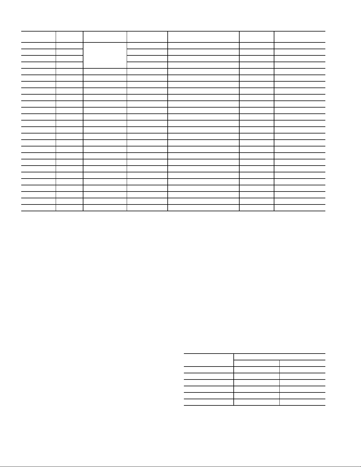
Table 10 — EMM Board Inputs and Outputs
*Teflon is a registered trademark of DuPont.
CHANNEL
CH 01 AI
CH 02 AI SPACETMP Space temperature AI-02 10K Thermistor
CH 03 AI — — AI-03 5/10K Thermistor
CH 04 AI — — AI-04 5/10K Thermistor
CH 05 AI J7A SP_RESET Setpoint reset AI-06 0-5V
CH 06 AI J7B LIM_ANAL Capacity limit AI-07 0-5V
CH 07 AO J8 CAP_T % Total capacity running AO-01 0-10VdC
CH 08 DI J4, CH8 OCC_OVSW Occupancy override DI-01 —
CH 09 DI J4, CH9 LIM_SW2 Demand limit SW2 DI-02 —
CH 10 DI J4, CH10 REM_LOCK Remote lockout switch DI-03 —
CH 11a DI J4, CH11A ICE_SW Ice done DI-04 —
CH 11b DI J4, CH11B — — DI-05 —
CH 12 DI J5, CH12 — — DI-06 —
CH 13 DI J5, CH13 — — DI-07 —
CH 14 DI J5, CH14 — — DI-08 —
CH 15 DI J5, CH15 — — DI-09 —
CH 16 DO J2A CP_A Compressor A run status DO-01 Triac
CH 17 DO J2A CP_B Compressor B run status DO-02 Triac
CH 18 DO J2A — — — —
CH 19 DO J2A — — — —
CH 20 DO J2B — — — —
CH 21 DO J2B — — — —
CH 22 DO J2B — — — —
CH 23 DO J2B — — — —
CH 24 DO J3 SHUTDOWN Shutdown relay DO-09 Relay
CH 25 DO J3 ALERT Alert relay DO-10 Relay
IN/OUT
TYPE
BOARD
CONNECTOR
J6
CCN POINT
— — AI-01 5/10K Thermistor
Local Equipment Network — Information is trans-
mitted between modules via a 3-wire communication bus or
LEN (Local Equipment Network).
Board Addresses — All boards (except the Touch Pilot
display and the Energy Management Module board) have DIP
switches to set the address.
Control Module Communication
RED LED — Proper operation of the control boards can be
visually checked by looking at the red status LEDs (lightemitting diodes). When operating correctly, the red status
LEDs will blink in unison at a rate of once every 2 seconds.
If the red LEDs are not blinking in unison, verify that correct power is being supplied to all modules and that all communication wiring is connected securely. Be sure that the
Touch Pilot
If necessary, reload current software. If the problem still
persists, replace the Touch Pilot module. A red LED that is
lit continuously or blinking at a rate of once per second or
faster indicates that the board should be replaced.
GREEN LED — All boards have a green LEN (Local
Equipment Network) LED which should be blinking when-
™
module is supplied with the current software.
POINT
DESCRIPTION
Carrier Comfort Network® (CCN) Interface —
All 30XV units can be connected to the CCN, if desired. The
communication bus wiring is a shielded, 3-conductor cable
with drain wire and is field supplied and installed. The system
elements are connected to the communication bus in a daisy
chain arrangement. The positive pin of each system element
communication connector must be wired to the positive pins of
the system elements on either side of it. The negative and signal ground pins of each system element must also be wired in
the same manner. Wiring connections for CCN should be made
at TB3. Consult the CCN Contractor’s Manual for further information. See Fig. 19.
NOTE: Conductors and drain wire must be 20 AWG
(American Wire Gage) minimum stranded, tinned copper.
Individual conductors must be insulated with PVC, PVC/
nylon, vinyl, Teflon*, or polyethylene. An aluminum/
polyester 100% foil shield and an outer jacket of PVC,
PVC/nylon, chrome vinyl, or Teflon with a minimum
operating temperature range of –20 C to 60 C is required.
See Table 11 for recommended wire manufacturers and
part numbers.
Table 11 — CCN Communication Bus Wiring
ever power is on. If the LEDs are not blinking as described
check LEN connections for potential communication errors
at the board connectors. A 3-wire bus accomplishes communication between modules. These 3 wires run in parallel
from module to module. They connect to J9 on EMM and
AUX boards, and to J12 or J13 on SIOB boards. A valid
unit configuration must be in the Touch Pilot module for
proper LEN communication.
MANUFACTURER
Alpha 1895 —
American A21451 A48301
Belden 8205 884421
Columbia D6451 —
Manhattan M13402 M64430
Quabik 6130 —
I/O POINT
NAME
PART NUMBER
Regular Wiring Plenum Wiring
INPUT/OUTPUT
TYPE
16
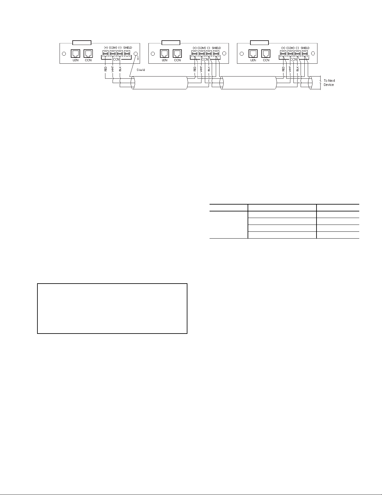
It is important when connecting to a CCN communication
a30-4082
Fig. 19 — Touch Pilot CCN Communication Wiring
bus that a color-coding scheme be used for the entire network
to simplify the installation. It is recommended that red be used
for the signal positive, black for the signal negative, and white
for the signal ground. Use a similar scheme for cables containing different colored wires.
At each system element, the shields of its communication
bus cables must be tied together. If the communication bus is
entirely within one building, the resulting continuous shield
must be connected to a ground at one point only. If the communication bus cable exits from one building and enters another,
the shields must be connected to grounds at the lightning suppressor in each building where the cable enters or exits the
building (one point per building only). To connect the unit to
the network:
1. Turn off power to the control box.
2. Cut the CCN wire and strip the ends of the red (+), white
(ground), and black (–) conductors. (Substitute appropriate colors for different colored cables.)
3. Connect the red wire to (+) terminal on TB3 of the plug,
the white wire to COM terminal, and the black wire to the
(–) terminal.
4. The RJ14 CCN connector on TB3 can also be used, but is
only intended for temporary connection (for example, a
laptop computer running Service Tool).
IMPORTANT: A shorted CCN bus cable will prevent
some routines from running and may prevent the unit
from starting. If abnormal conditions occur, disconnect the CCN bus. If conditions return to normal,
check the CCN connector and cable. Run new cable if
necessary. A short in one section of the bus can cause
problems with all system elements on the bus.
CONFIGURATION (SOFTWARE)
Touch Pilot™ Operation Configuration
Tables —
ured for a range of operating conditions and equipment
arrangements. The following parameters should be configured
based on unique system layout and operating requirements.
The system parameters may be configured through the
Touch Pilot interface or remotely through the CCN. Table 12
shows the Touch Pilot configuration required to access the unit
on the CCN.
Table 12 — Touch Pilot Controller Identification
PATH DISPLAY NAME VALUE
Main Menu
Configuration
Menu
Control
Identification
The Touch Pilot control system can be config-
Configuration Table
CCN Element Number Default=1
CCN Bus Number Default=0
CCN Baud Rate Default=9600
Location Description Default=Blank
Touch Pilot Menu Tables — Touch Pilot operation is
controlled by configuration information entered in the configuration tables listed in Tables 13-16. Access to different parameters may be available to all users (BASIC) or password-protected (USER, FACTORY, or SERVICE). See Appendix A for detailed descriptions of all control tables and parameters.
Remote Alarm and Alert Relays — The 30XV chiller
can be equipped with remote alert and remote alarm annunciator contacts. Both relays connected to these contacts must be
rated for a maximum power draw of 10 va sealed, 25 va inrush
at 24 volts. The alarm relay, indicating that the complete unit
has been shut down, can be connected to TB5-12 and TB5-21.
Refer to unit wiring diagrams. For run relay, indicating that at
least 1 circuit is off due to an alert state, a field-supplied and installed relay must be connected between TB5-13 and TB5-20.
17
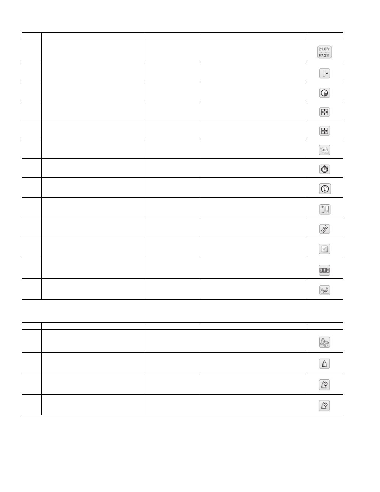
Table 13 — Main Menu Table
ITEM CCN MENU NAME ACCESS MENU TEXT DESCRIPTION MENU ICON
1 GENUINT ALL General Parameters
2 TEMP ALL Temperatures
3 PRESSURE ALL Pressures
4 INPUTS ALL Inputs Status
5 OUTPUTS ALL Outputs Status
6 PUMPSTAT ALL Pump Status
7 RUNTIME ALL Run Times
8 MODES ALL Modes
9 SETPOINT USER Setpoint Table
10 CONFIG USER Configuration Menu
11 QCK_TEST SERVICE Quick Test
12 MAINTAIN SERVICE Maintenance Menu
13 TRENDING ALL Trendings
Table 14 — Alarms Menu Table
ITEM CCN MENU NAME ACCESS MENU TEXT DESCRIPTION MENU ICON
1 ALARMRST USER Reset Alarms
2 CUR_ALM ALL Current Alarms
3 ALMHIST1 ALL Alarm Historic
4 ALMHIST2 ALL Major Alarm Historic
18
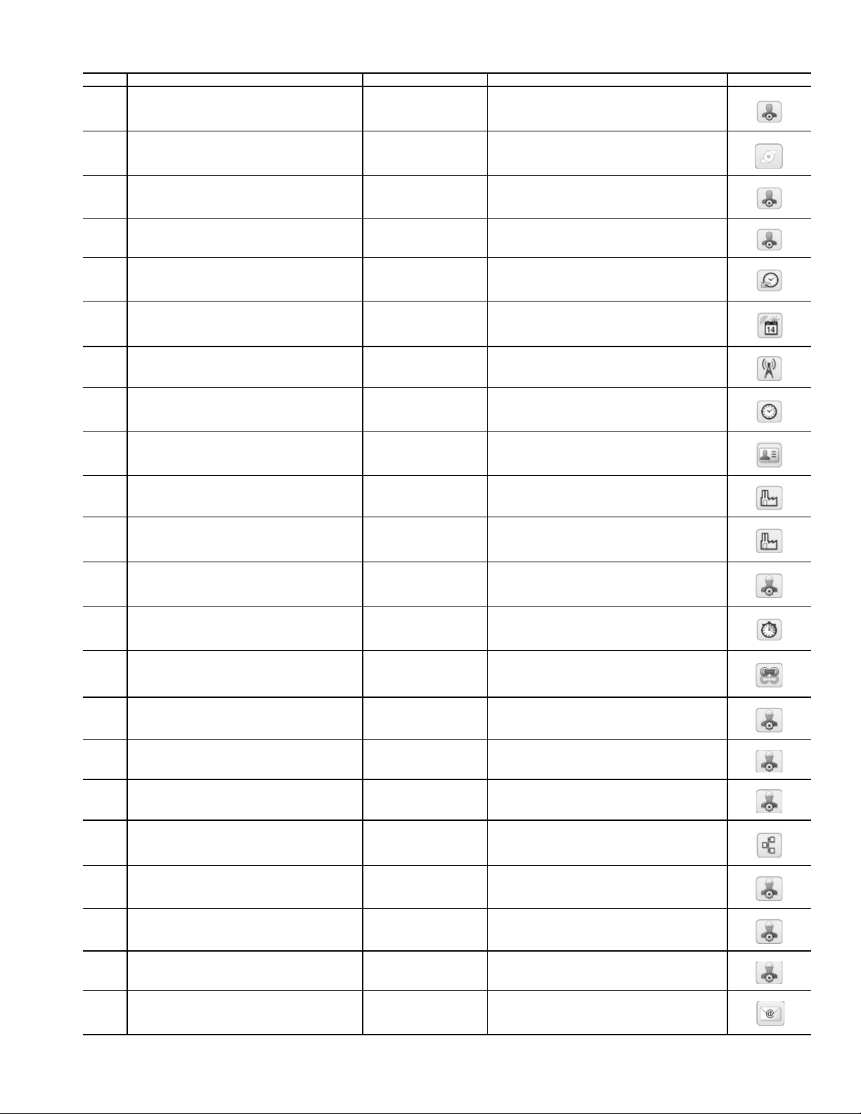
Table 15 — Configuration Menu Table
ITEM CCN MENU NAME ACCESS MENU TEXT DESCRIPTION MENU ICON
1 GEN_CONF USER General Configuration
2 PUMPCONF USER Pump Configuration
3 USERCONF USER User Configuration
4 RESETCFG USER Reset Configuration
5 SCHEDULE USER Schedule Menu
6 HOLIDAY USER Holiday Menu
7 BROCASTS USER Broadcast Menu
8 DATETIME USER Date/Time Configuration
9 CTRL_ID USER Control Identification
10 FACTORY FACTORY Factory Parameters
11 FACTORY2 FACTORY Factory2 Parameters
12 SERVICE SERVICE Service Parameters
13 UPDTHOUR SERVICE Update Running Hour
14 MST_SLV SERVICE Master Slave Config
15 CMP_PI* SERVICE Comp PI Parameters
17 EXV_CFG* SERVICE EXV Configuration
18 DELTA* SERVICE Action Parameters
19 BACNET SERVICE BACnet Parameters
20 FAN_CFG* SERVICE Fan Configuration
21 ECO_PI* SERVICE EXV ECO PI Parameters
22 CP_UNABL SERVICE Compressor Enable
23 EMAILCFG SERVICE Email Configuration
* Tables available only through the CCN.
19
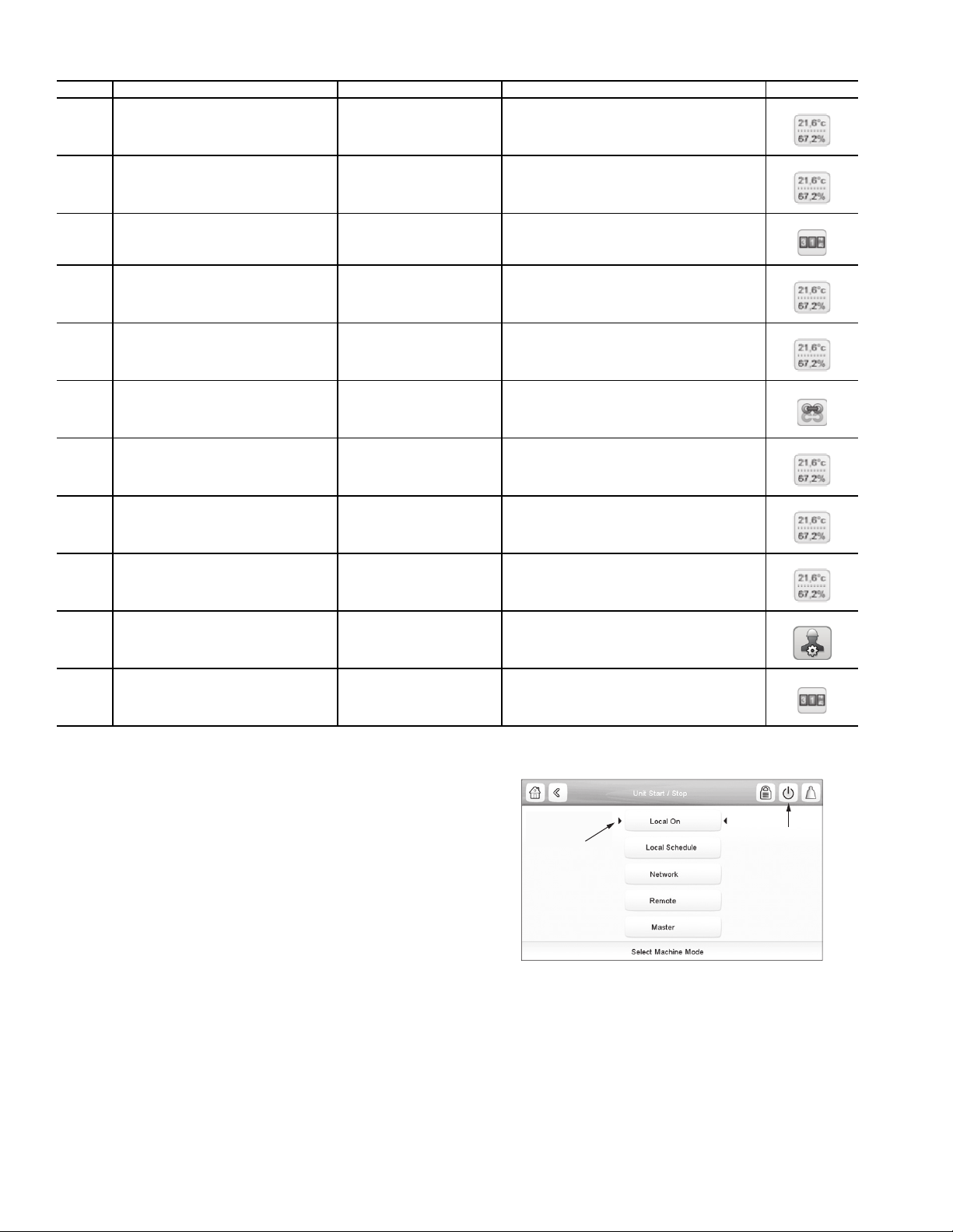
Table 16 — Maintenance Menu Table
Fig. 20 — Machine Control Methods
ITEM CCN MENU NAME ACCESS MENU TEXT DESCRIPTION ICON
1 CAPACTRL SERVICE Capacity Control
2 VLT_DRV SERVICE VLT Drive Maintenance
3 LAST_POR SERVICE Last PowerOn Reset
4 EXV_CTRL SERVICE EXV Control
5 LIMITS SERVICE Control Limits
6 M_MSTSLV SERVICE Master Slave Control
7 ECO_CTRL SERVICE EXV Eco. Control
8 FAN_CTRL SERVICE Fan Control
9 FAN_DRV SERVICE Fan Drive Maintenance
10 TBLSHT SERVICE Troubleshoot Info
11 FAN_DRV2 SERVICE Fan Drive Addressing
Machine Control Methods — The unit state is deter-
mined based on a number of factors, including its operating
type, active overrides, open contacts, master/slave configuration, or alarms triggered due to operating conditions. These parameters can be controlled by one of the following methods:
• Locally on unit: Local Control type
• Remotely through a user contact: Remote Control type
• Remotely through the CCN network: CCN Control type
The main interface Start/Stop button is used to select one of
the above control types. In addition, when the Local control
type is selected, this button can be used to select a particular
functional mode: On, Off or Schedule mode. See Fig. 20. If the
Start/Stop button is green the unit is running. If the Start/Stop
button is gray the unit is not running. If the button is flashing
green then the unit is preparing to start.
Table 17 summarizes the available operating types.
SHOWS THE
LAST MODE
SELECTED
STA RT / STOP
BUTTON
a30-5917
20
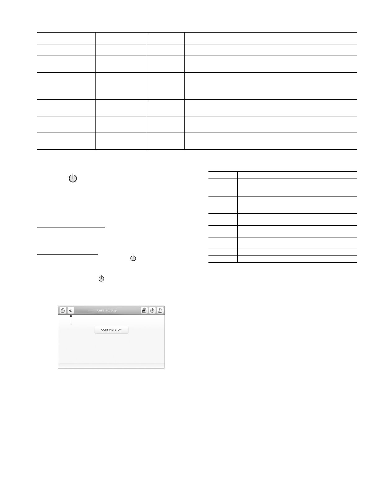
Table 17 — Operating Types
BACK
BUTTON
a30-5894
Fig. 21 — Confirm Stop
OPERATING TYPE CONTROL METHOD
LOCAL — OFF
LOCAL — ON
LOCAL — SCHEDULE
NETWORK
REMOTE
MASTER
Local Off
Local On
Local Schedule
CCN None
Remote None
Master Master
OPERATING
MODES
OPERATING TYPE SELECTION — The operating type
is selected through the main interface by pressing the Start/
Stop button .
If the unit is running, pressing the Start/Stop button displays a screen with a Confirm Stop button (see Fig. 21),
which when pressed switches the chiller to Local Off mode.
If the unit is Off, pressing the Start/Stop button shows a list of
operating types with the currently selected type corresponding to the last running operating type (Fig. 20).
Start/Stop Selection Screen
— In Local mode (LEN bus), the
Touch Pilot treats the Start/Stop button as a hotkey, and goes
directly to the Start/Stop selection screen. In CCN mode, the
Touch Pilot ignores Start/Stop key presses.
Start a Stopped Machine
mode, press the gray Start/Stop button
— With the unit in the Local off
to display the list of
operating modes and select the required mode.
Stop a Running Machine
— To stop a running unit, press the
green Start/Stop button . Confirm the unit shutdown by
pressing Confirm Stop or cancel by pressing the Back button
(Fig. 21).
Once the unit has been stopped, the Home screen is
displayed.
NOTE: Start/Stop a machine is not authorized through a web
connection for security reasons.
Machine On/Off Function — The machine operating
state can be viewed by going to Main Menu General Parameters Run Status. Table 18 summarizes possible unit states.
DESCRIPTION
The unit is under Local control method. It will remain halted and will ignore all
CCN network commands and remote switch contacts.
The unit is under Local control method and will be allowed to start. The control
will ignore all remote control contacts (except the demand limit contact) and all
CCN network force commands (except the Emergency Stop Command).
The unit is under Local control method and will be allowed to start if the
schedule #1 is occupied (chil_occ). Otherwise, the unit will remain off. The
control will ignore all remote control contacts (except the demand limit contact) and all CCN network force commands (except the Emergency Stop
Command).
The unit is under CCN control method and will be controlled by CCN force
commands. The control will ignore all remote control contacts (except the
demand limit contact).
The unit is under Remote control method and will be controlled by the start/
stop and set point contacts. In this mode, no CCN force command can affect
the unit control except the Emergency Stop Command.
The unit is configured as the master unit in a two-unit master/slave plant. The
master unit control method can be done locally, remotely or through CCN
commands upon the master/slave configuration.
Table 18 — Unit States
STATE DESCRIPTION
Off Unit is commanded to be off
Stopping
Delay
Running
Ready
Override
Tripout Unit is Off due to an alarm
Test Unit is in Quick Test
Unit is currently stopping (after a manual, emergency,
or shutdown request). Next state will be Off.
Unit is in delay at start-up (waiting for the end of the
On/Off delay to be reached). Next state will be
Running.
Unit compressor capacity is more that 0% (unit has
started running)
Unit compressor capacity is 0%. Unit is ready to
start.
The compressor cannot start because of an override
(SST, SCT, etc.)
Table 19 summarizes the unit control method and stop or go
status with regard to the following parameters set in the Touch
Pilot:
• Active operating type: Operating Type as selected on the
unit Start-Stop screen.
• CHIL_S_S: Current CCN chiller start/stop force com-
mand (enable/disable). Main Menu General Parame-
ters Net:Cmd Start/Stop.
• Onoff_sw: Start-stop contact status when unit is under
remote operating type. Main Menu Inputs Status
Remote On/Off Switch.
• chil_occ state: Chiller occupied state. If the occupancy
override input switch is closed, the chiller remains occu-
pied regardless of the set point scheduled selection. Main
Menu General Parameters Net:Cmd Occupied.
• ms_ctrl: Master control type. This parameter status will
determine if the master unit is going to be controlled
locally, remotely, or through CCN. Main Menu Main-
tenance Menu Master Slave Control (0=disabled,
1=master, 2=slave).
• EMSTOP: CCN emergency stop command (enable/dis-
able). Main Menu General Parameters Emergency
Stop
• Alarm shutdown: Unit is totally stopped due to alarm.
21
Table 19 — Start/Stop Control
ACTIVE OPERATING TYPE
Local Off (LOFF) — — — — — — Local Off
Local On (L-C) — — — — Disable No Local On
Local Schedule (L-SC)
Remote (rEM)
CCN
Master (MA St)
—————
LEGEND
chil_occ — Chiller Occupied State
CHIL_S_S — CCN Chiller Start/Stop Command
EMSTOP — Emergency Stop
L-C — Local Control Operating Type
L-SC — Local Schedule Operating Type
MA St — Master/Slave Operating Type
ms-ctrl — Master/Slave Control
Onoff_sw — Remote On/Off Switch
rEM — Remote Operating Type
CHIL_S_S Onoff_sw ms-ctrl chil_occ state EMSTOP
— — — Occupied Disable No Local On
— — — Unoccupied — — Local Off
— Open — — — — Remote Off
— — — Unoccupied — — Remote Off
Closed Occupied — — Remote On
Disable — — — — — CCN Off
— — — Unoccupied — — CCN Off
Enable — — Occupied Disabled No CCN On
— — Local Unoccupied — — Local Off
— Open Remote — — — Remote Off
— — Remote Unoccupied — — Remote Off
Disable — CCN — — — CCN Off
— — CCN Unoccupied — — CCN Off
— — Local Occupied Disable No Local On
— Closed Remote Occupied Disable No Remote On
Enable CCN Occupied Disable No CCN On
All of the control type and unit state combinations listed in
Table 19 will determine the actual unit running state. In addition, when under remote type control, unit Start/Stop actions
will be determined by both On/Off and Occupied/Unoccupied
status if the changeover option is enabled. If the changeover
option is not enabled, only the On/Off switch will be used to
command the unit to Start or Stop.
NOTE: When changing from one control method (Local,
Remote, or CCN) to another, the unit will observe a transition
through the Off state before being allowed to start again. At
this time the on-to-off delay is always applied.
MACHINE START DELAY — An option to delay the start
of the machine is available. This parameter is useful in keeping
multiple machines from starting at the same time in case of a
power failure. The parameter has a factory default of 1 minute.
This parameter also has a role in the timing for a chilled water
flow switch alarm. To configure this option with the Touch Pilot display, select Main Menu Configuration Menu General Configuration and select Unit Off to On Delay.
FAST LOADING — The Fast Capacity Recovery function
allows for an accelerated unit start-up. This is especially useful
following brief power outages at data centers where rapid restart can keep data center operating. This should not be used on
normal comfort cooling applications. To activate the Fast Capacity Recovery, go to Main Menu Configuration Menu
Service Parameters and set Fast Capacity Recovery. The available options are as follows:
• 0 (Normal Loading Sequence): Follows the set delays for
unit and circuit start up
• 1 (Quick Start Loading): Ignores Capacity Override #53
(ON/OFF Delay)
• 2 (Fast Capacity Recovery): Removes the unit start-up
delay, ignores Capacity Override #53 (ON/OFF Delay),
and allows both compressors to start at the same time
(with a 10-second delay between starts)
PARAMETER STATUS
Chilled Water Set Point Configuration — The
chilled water set point and fluid type configuration will determine the chiller operating conditions.
FLUID SET POINT CONTROL LOCATION — The factory default for the chilled water fluid set point is to control
to the leaving water temperature. An option to configure the
machine for entering water control is available. To configure this option go to Main Menu Configuration Menu
Service Parameters. The default for Entering Fluid Control
is No (leaving fluid control is the default condition).
COOLING SET POINT SELECTION — The control point
represents the water temperature that the unit must produce.
The unit will vary the capacity depending on the unit load
operating conditions in order to satisfy the set point. The control point (CTRL_PNT) is calculated based on the active set
point and the reset calculation, where Control Point = Active
Setpoint + Reset. (See the section Temperature Reset on
page 33 for more information about Reset.) The forced value
can be used instead of any other set point calculation only
when Network is selected as the operating type for the unit (go
to Main Menu General Parameters to verify operating type).
DEFINING SET POINTS — The cooling set points are set
via the Setpoint Table (Main Menu Setpoint Table). Cooling
Setpoint 1 and Cooling Setpoint 2 are the temperatures that are
selectable as the Active Set Points for the unit operation. These
temperatures will be limited by the type of fluid in the system
(see Table 20).
In addition to the Cooling set points, users can also select
the Cooling Ice Setpoint and Cooling Ramp Loading from this
menu. See the Ice Storage Operation section on page 40 for
more details about the Cooling Ice Setpoint. Ramp Loading
limits the rate at which the unit will change cooling water temperature (default is 1º F/min [0.6º C/min]).
All default set points are based on Leaving Water Control
(Entering Fluid Control, EWTO set to No). Values must be
Alarm
Shutdown
Enable — — Off
—Yes— Off
CONTROL
METHOD
confirmed for the individual set points. Limits for the set points
UNIT
STATUS
22
are listed in Table 20. These values depend on the Evaporator
Fluid Type and the Brine Freeze Setpoint (see Chilled Water
Fluid Type Selection on page 25).
Table 20 — Evaporator Fluid Set Point Limits
Set Point
Limits
Minimum* 38 F (3.3 C) N/A N/A
Maximum 60 F (15.5 C) N/A N/A
*The minimum set point for brine applications is related to the brine
freeze set point. The set point is limited to be no less than the brine
freeze set point + 4° F (2.2° C).
EVAPORATOR FLUID TYPE (flui_typ)
1 = Water 2 = Medium Brine 3 = Low Brine
CURRENT OPERATING SET POINT — Depending on
the current operation type, the active set point can be selected manually in the Main Menu, with the dry user contacts, with network commands (CCN or BACnet), or automatically with the set point time schedule (Occupancy
Schedule 2).
Set points can be selected manually through the main
interface when the unit is in Local operating type, through
contacts when the unit is in Remote operating type, or
through the RS485 bus when unit is in CCN mode.
Set points can also be selected automatically through a
set point time schedule: when the period is occupied Cooling Setpoint 1 will be activated, and when the period is
Unoccupied Cooling Setpoint 2 will be active. When in local operating type, time schedule is available if the Setpoint Select Variable is set to AUTO (see below). In remote operating type, the AUTO mode will be available unless the dual set point control through contacts has already
been selected. In CCN mode, the set point selection always depends on the time schedule. The set point can be
forced through the SP_OCC CCN point (0 = Occupied =
Cooling Setpoint 1, 1 = Unoccupied = Cooling Setpoint 2).
Set point selection offers three different control options
(Main Menu General Parameters Setpoint Select): Auto,
Setpoint 1, and Setpoint 2.
• 0 = Auto: The active cooling set point will be determined
by the configured Occupancy Schedules. See the Defin-
ing Occupancy Schedule section for details on setting the
schedules. Depending on the Ice Storage configuration
Table 21 — Active Cooling Set Point Parameters
and ice contact state, the active set point may alternately
be set to the Cooling Ice Setpoint.
• 1 = Setpoint 1: The active cooling set point will be Cooling Setpoint 1 defined in the set point table.
• 2 = Setpoint 2: The active cooling set point will be Cooling Setpoint 2 defined in the set point table. Depending
on the Ice Storage configuration and ice contact state, the
active set point may alternately be set to the Cooling Ice
Setpoint.
SETPOINT OCCUPANCY — Setpoint Occupancy is the default configuration for the Setpoint Select variable. When Setpoint Select (Main Menu General Parameters Setpoint
Select) is configured to 0 (Auto), the unit’s active set point is
based on the programmed occupancy schedules. Under Time
Schedule 1 (OCCPC01S), the unit controls to Cooling Set
Point 1 (csp1) during the occupied periods. If the Time Schedule 2 (OCCPC02S) is in use, the unit’s active set point is based
on Cooling Set Point 1 (csp1) (Main Menu Setpoint Table
Cooling Setpoint 1) during the occupied period and Cooling
Set Point 2 (csp2) (Main Menu Setpoint Table Cooling
Setpoint 2) during the unoccupied period. The two schedules
are used together to determine periods when the chiller will be
controlling to Setpoint 1, Setpoint 2, or Off.
See Table 21 for details on how the active cooling set point is
determined based on unit operating type and parameter settings.
DEFINING OCCUPANCY SCHEDULE — Two internal
Time Schedules are available and must be field programmed.
Occupancy Schedule 1 (OCCPC01S) is used for single set
point On/Off control. Occupancy Schedule 2 (OCCPC02S) is
used in combination with OCCPC01S for dual set point On/Off
and Occupied/Unoccupied set point control. To access the
Schedule screens, go to Main Menu Configuration Menu
Schedule Menu.
If the chiller is to be controlled to a single set point, use
Schedule 1 (OCCPC01S). This type of schedule will start and
stop the machine only. During the unoccupied times, the chiller
will be off. The unit start/stop schedule OCCPC01S has a default setting of always occupied. If the chiller is to be controlled
to 2 set points, occupied and unoccupied, also use Schedule 2
(OCCPC02S). Cooling Setpoint 1 will be active during occupied periods, and Cooling Setpoint 2 will be active during unoccupied periods.
OPERATING
TYPE
Local
Remote
Network
* Ice Storage Configuration and Ice Done Contact apply only to units
with energy management module (EMM).
Setpoint
Selection
sp-1 Default Any Any Default Cooling Setpoint 1
sp-2 No Any Any Default Cooling Setpoint 2
sp-2 Yes Closed Any N/A Cooling Setpoint 2
sp-2 Yes Open Any N/A Cooling Ice Setpoint
automatic Default Any Any Occupied Cooling Setpoint 1
automatic No Any Any Unoccupied Cooling Setpoint 2
automatic Yes Closed Any Unoccupied Cooling Setpoint 2
automatic Yes Open Any Unoccupied Cooling Ice Setpoint
Default Default Any Open Default Cooling Setpoint 1
Default No Any Closed Default Cooling Setpoint 2
N/A Yes Closed Closed N/A Cooling Setpoint 2
Default Yes Open Closed Default Cooling Ice Setpoint
Default Default Any Any Occupied Cooling Setpoint 1
Default Default Any Any Unoccupied Cooling Setpoint 2
Ice Storage
Configuration*
PARAMETER STATUS
Ice Done
Contact*
23
Setpoint
Switch
Schedule 2 Status
ACTIVE SETPOINT
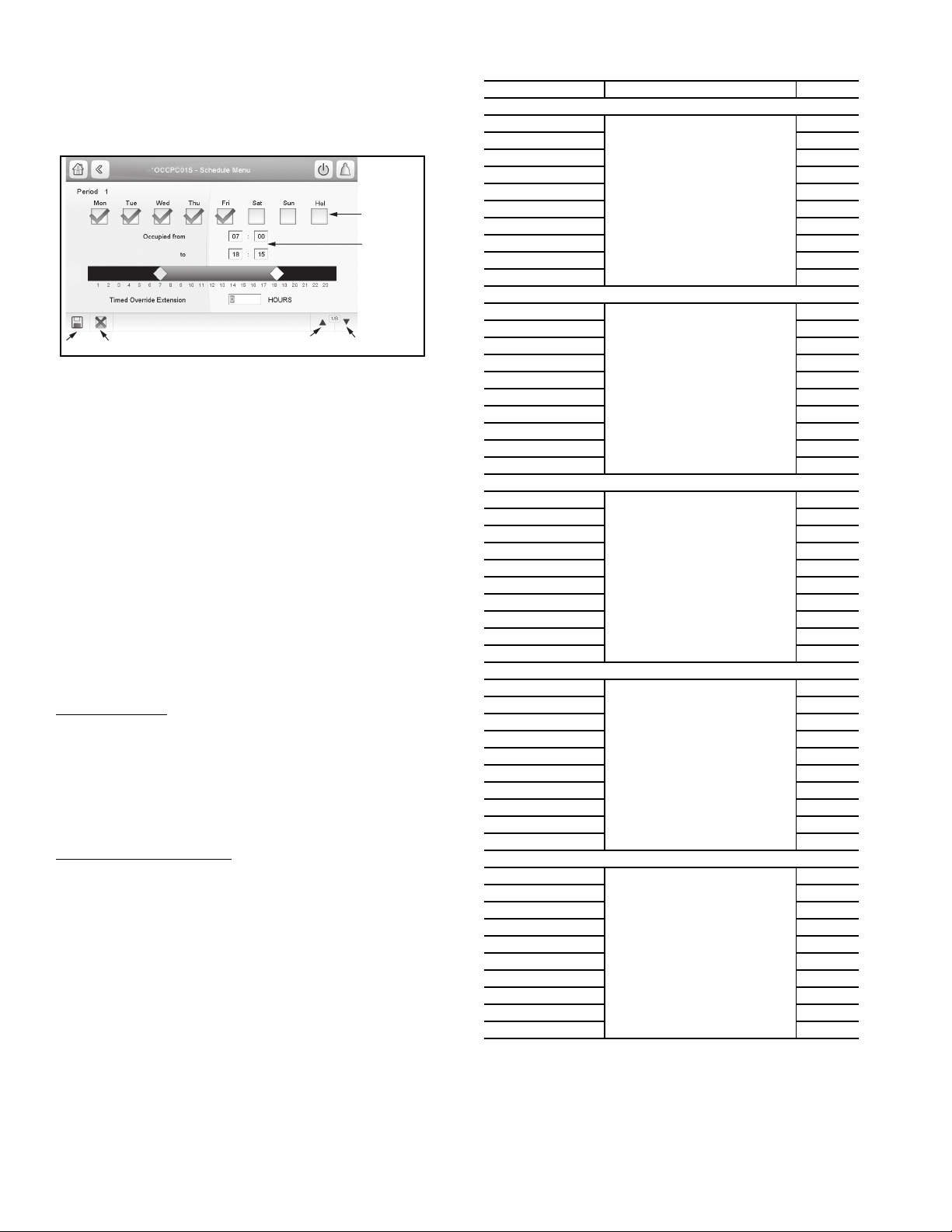
To set the occupancy schedules, select OCCPC01S or OC-
Fig. 22 — Schedule Menu
SELECT THE
DAYS FOR
THIS PERIOD
SCHEDULE
SET THE
OCCUPIED
TIMES
SAVE
CANCEL
PREVIOUS
PERIOD
NEXT
PERIOD
CPC02S and select the applicable days for the displayed time
schedule period. The selected period will be displayed as a
green band on the timeline. Press the Save button to confirm or
the Cancel button to cancel changes. See Fig. 22.
The schedules consist of 8 user-configurable occupied time
periods. The control supports time schedules for local control,
remote control, and ice building. These time periods can be
flagged to be in effect or not in effect on each day of the week.
The day begins at 00:00 and ends at 24:00. The machine is in
unoccupied mode unless a scheduled time period is in effect. If
an occupied period is to extend past midnight, the occupied period must end at 24:00 hours (midnight) and a new occupied
period must be programmed to begin at 00:00 hours.
In the example in Table 22, an early morning pulldown time
period is scheduled for Monday morning from 12:00 AM to
3:00 AM. The occupied period starts at 7:00 AM, Monday
through Saturday. The occupied time ends at 6:00 PM on Monday and Tuesday, 9:30 PM on Wednesday, 5:00 PM on Thursday and Friday, and 12:00 PM on Saturday.
NOTE: This example schedule was designed to illustrate
the programming of the schedule function and is not
intended as a recommended schedule for chiller operation.
Holiday Schedule
— The unit control allows up to 16 holiday
periods. Each holiday period is defined by three parameters:
the month, the start day, and the duration of the holiday period.
During the holiday periods, the controller will be in occupied
or unoccupied mode, depending on the periods validated as
holidays. The Holiday Configuration Table is accessed by
Main Menu Configuration Menu Holiday Menu. Select
one of the 16 available Holiday periods (HOLDY_01 through
HOLDY_16) to define the holiday.
CCN Global Time Schedule
onboard occupancy schedules (OCCPC01S and OCCPC02S),
the Touch Pilot
™
can also receive a time schedule broadcast
— In addition to the two
from another element in the CCN network.
The 30XV with Greenspeed
®
intelligence chillers can be
configured to follow a CCN Global Time Schedule broadcast
by another system element. The Occupancy Table (OCCPC01S) number must be changed to configure the unit to
broadcast a Global Time Schedule. The Schedule Number can
be set from 65 to 99 (OCCPC65S to OCCPC99S). When
OCC1PxxS is set to a value of 65 or greater and all attached
schedules are 00:00 (that is, no occupied time periods), an occupancy flag is broadcast over the CCN every time it transitions from occupied to unoccupied or vice-versa. The ComfortVIEW™ Network Manager’s Configure and Modify commands or the Service Tool’s Modify/Names function must be
used to change the number of the Occupancy Equipment Part
Table Name (OCCPC01E) to the Global Schedule Number.
The Schedule Number can be set from 65 to 99 (OCCPC65E
to OCCPC99E).
Table 22 — Configuring Schedules (Example)
ITEM PATH VALUE
Period 1
Occupied from
Occupied to 03:00
Monday Select Yes
Tuesday Select No
Wednesday Select No
Thursday Select No
Friday Select No
Saturday Select No
Sunday Select No
Holiday Select No
Occupied from
Occupied to 18:00
Monday Select Yes
Tuesday Select Yes
Wednesday Select No
Thursday Select No
Friday Select No
Saturday Select No
Sunday Select No
Holiday Select No
Occupied from
Occupied to 21:30
Monday Select No
Tuesday Select No
Wednesday Select Yes
Thursday Select No
Friday Select No
Saturday Select No
Sunday Select No
Holiday Select No
Occupied from
Occupied to 17:00
Monday Select No
Tuesday Select No
Wednesday Select No
Thursday Select Yes
Friday Select Yes
Saturday Select No
Sunday Select No
Holiday Select No
Occupied from
Occupied to 12:00
Monday Select No
Tuesday Select No
Wednesday Select No
Thursday Select No
Friday Select No
Saturday Select Yes
Sunday Select No
Holiday Select No
Main Menu
Menu Schedule Menu
OCCPC01S or OCCPC02S
Main Menu
Menu
OCCPC01S or OCCPC02S
Main Menu
Menu Schedule Menu
OCCPC01S or OCCPC02S
Main Menu
Menu
OCCPC01S or OCCPC02S
Main Menu
Menu
OCCPC01S or OCCPC02S
Configuration
Page 1
Period 2
Configuration
Schedule Menu
Page 2
Period 3
Configuration
Page 3
Period 4
Configuration
Schedule Menu
Page 4
Period 5
Configuration
Schedule Menu
Page 5
00:00
07:00
07:00
07:00
07:00
When OCC1PxxS is set to a value of 65 or greater and a
time schedule is configured for at least one occupancy period,
the system will assume that the unit is going to be the master
element for this schedule (the system element doing the broadcasting). In that case the unit Equipment and Supervisory part
table names will be automatically modified to OCCPCxxE
and OCCPCxxS.
24
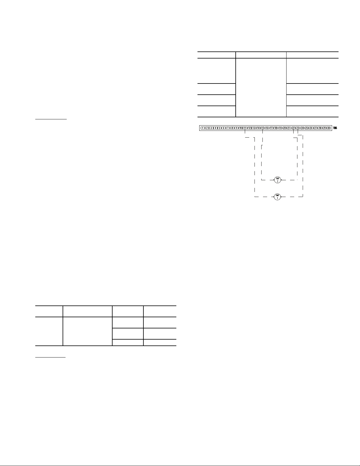
By configuring their appropriate Time Schedule decisions
Fig. 23 — Wiring for Evaporator Pump Control
to the same number, other devices on the network can follow
this same schedule. The Enable/Off/Remote Contact must be in
the Enable position or the Remote Contact position with the
contacts closed for the unit to operate.
The Unit Run Status (Main Menu General Parameters
Run Status) will indicate the current status of the machine depending on the schedule. The unit Occupied status (Main
Menu General Parameters Setpoint Occupied) will indicate the current occupied schedule according to the schedule,
either NO or YES.
The Status Unit Control Type (Main Menu General Parameters) will be 0 when the switch is Off. The Status Unit
Control Type will be 2 when the Enable/Off/Remote Contact
switch input is On.
CCN Control
— To operate under this control, Network must
be selected under the Select Machine Mode accessed by pressing the Start/Stop button (see the Operating Type Selection section on page 21).
An external CCN device such as Chillervisor controls the
On/Off state of the machine. Careful evaluation of Chilled Water Plant control is necessary. In the event Local Control is established, be sure that all pumps, valves, and other devices are
capable of operating properly. In the event of a loss of communication with the network, the machine will start and be controlled locally. The CCN device forces the variable CHIL_S_S
to control the chiller. The Unit Run Status (Main Menu
General Parameters Run Status) will indicate the current
status of the machine (OFF, RUNNING, STOPPING or DELAY), depending on the CCN command. The unit Occupied
status (Main Menu General Parameters) will indicate the
current occupied state according to the CCN command and
will be displayed as either NO or YES. The Status Unit Control
Type (ctrl_typ) will be LOCAL OFF when the Start/Stop button is Off. The Status Unit Control Type will be CCN when the
Enable/Off/Remote Contact switch input is Closed and the
CHIL_S_S variable is Stop or Start. For dual chiller control
applications, the slave chiller must be enabled using the CCN
CONTROL option.
CHILLED WATER FLUID TYPE SELECTION — The
chilled water fluid type must be configured to obtain the proper
leaving water set point control range and freeze protection. The
Evaporator Fluid Type (flui_typ) (Main Menu Configuration Menu Service Parameters Evaporator Fluid Type)
can be set to water or brine.
To configure this option:
DISPLAY
NAME
Evaporator
Fluid
Type
Fresh Water
PATH VALUE
1 = Water 38 to 60 F
Main Menu
Configuration Menu
Service Parameters
2 = Medium
brine
3 = Low brine N/A
— Configure the unit Evaporator Fluid Type to
SETPOINT
RANGE
(3.3 to 15.5 C)
N/A
Water for units without brine or glycol installed in the chilled
water loop. The factory default fluid type is fresh water. This
option will allow for a water temperature set point range of 38
to 60 F (3.3 to 15.5 C). With water as the selection, the freeze
point is fixed at 34 F (1.1 C).
Evaporator Pump Control — Evaporator pump con-
trol is required on all units unless the chilled water pump runs
continuously or the chilled water system contains a suitable
antifreeze solution. The 30XV units with Greenspeed
ligence can be configured for single or dual external evaporator pump control with the standard controls. In addition to the
pumps, all wiring including connections to the pump contactor and a feedback circuit from the contactor must be field
®
intel-
supplied. Table 23 summarizes evaporator pump configuration parameters. Fig. 23 shows the wiring.
Table 23 — Evaporator Pump Configuration
Parameters
DISPLAY NAME PATH VALUE
Evaporator
Pumps
Sequence
Pump Auto
Rotation Delay
Pump Sticking
Protection
Flow Checked
If Pump Off
Main Menu
Configuration Menu
Pump Configuration
0 = No Pump (Default)
1 = One Pump Only
2 = Two Pumps Auto
3 = Pump #1 Manual
4 = Pump #2 Manual
Default: 48 hrs.
(Range 24 to 3000 hrs.)
Default: No
Default: Yes
PUMP SELECTION — The Evaporator Pump Sequence
mode can be reached by following Main Menu Configuration Menu Pump Configuration. The available settings are:
• 0 = No Pump: The evaporator pump will not be controlled by the chiller. This is the default setting.
• 1 = One Pump Only: If only one pump is selected it will
be the active pump.
• 2 = Two Pump Auto: When two pumps are selected in
auto mode, only one pump will be allowed to run at a
time and the control will determine the On/Off state of
each pump. The control will start the pumps and automatically alternate the operation of the pumps to even the
wear on the pumps, based on the hours configured under
Pump Auto Rotation Delay (Main Menu Configuration Menu Pump Configuration Pump Auto Rotation Delay). If the difference between the operating hours
of the two pumps exceeds the Pump Auto Rotation Delay
the lead pump will change. If a flow failure is detected,
the other pump will attempt to start.
• 3 = Pump #1 Manual: Pump #1 will be the active pump.
• 4 = Pump #2 Manual: Pump #2 will be the active pump.
When the Evaporator Pumps Sequence is configured, the
evaporator pump output will be energized when the chiller enters an On state. Proof of flow from the chilled water flow
switch (CWFS) is required for the unit to start mechanical
cooling. The evaporator pump output is also energized when
certain alarms are generated. The evaporator pump output
should be used as an override to the external pump control if
evaporator pump control is not utilized. The evaporator pump
output is energized if a 10001 Evaporator Freeze Protection
alarm is generated, which provides additional freeze protection
if the system is not protected with a suitable antifreeze solution.
If the Master/Slave function is not active for the chiller
or if the Master/Slave function is active and the unit is the
lead, the pump will be turned on when the unit is in On,
Stopping or Delay state. In addition, when the unit is turned
off the pump will continue operating for 20 seconds after
25

the last compressor is turned off. The pump will be turned
on when requested by the evaporator heater function (see
the Evaporator Freeze Protection section on page 59).
PERIODIC PUMP QUICK START — The control system
has the ability to start the pumps periodically to maintain
bearing lubrication and seal integrity. This function will be
used when the unit is stopped for a long time period (e.g.,
during the winter season). If Pump Sticking Protection
(Main Menu Configuration Menu Pump Configuration Pump Sticking Protection) is set to YES and if the
unit is off at 2:00 PM, a pump will be started once each day
for 45 seconds. If the unit has 2 pumps, Pump 1 will be
started on even days (such as day 2, 4, or 6 of the month);
Pump 2 will be started on odd days (such as day 1, 3 or 5 of
the month). The default for this option is NO.
MASTER/SLAVE CHILLER PUMP OPERATION — If
the Master/Slave function is active and if the chiller is the
lag unit, then the pump will be turned on when the unit is in
On mode and if the unit active lag demand limit is greater
than 1%. Otherwise, the pump will be stopped 30 seconds
after the last compressor is turned off. However, if the lag
unit pump has been configured to run even if the unit is
commanded to stop (Main Menu Configuration Menu
Master Slave config Lag Unit Pump control = 1) then the
above condition will be ignored and the lag pump will run
all the time.
CHILLED WATER FLOW SWITCH STATUS — If Flow
Checked if Pump Off (Main Menu Configuration Menu
Pump Configuration Flow Checked if Pump Off) is
set to YES, the control will monitor the chilled water flow
switch status and will send an alarm if the pump is commanded off and the chilled water flow switch is closed. This
can provide the user with information of a faulty evaporator
pump contactor or a failed chilled water flow switch. This
parameter should be set to NO for series flow machines.
The factory default for this item is YES.
MANUAL OPERATION — The evaporator pumps can be
forced ON through the CCN when the chiller is off. This allows the unit to run with no delay and for an unlimited
length of time for flow rate calculations when the unit is installed on site. Manual operation of the pumps is controlled
through CCN points CPUMP_1 (Main Menu Pump Status) and CPUMP_2 (Main Menu Pump Status (0 = OFF,
1 = ON).
Circuit/Compressor Staging and Loading —
The AquaForce® 30XV chillers with Greenspeed® intelligence employ one compressor per circuit. As a result, circuit and compressor staging are the same. The control has
several control option parameters to load the compressors.
The circuit/compressor start can be configured as well as
the loading of each circuit/compressor.
CIRCUIT/COMPRESSOR STAGING — The control can
be configured to decide which circuit/compressor starts
first. Three options for this variable are allowed: Automatic
Lead-Lag, Circuit A Leads, or Circuit B Leads. The factory
default is Automatic Lead-Lag.
The automatic lead-lag function determines which circuit/compressor starts first to even the wear on the compressors. The control system determines the lead circuit to
equalize the operating time of each circuit (value weighted
by the number of start-ups of each circuit). As a result, the
circuit with the lowest number of operating hours always
starts first. The parameter can also be configured to always
start a particular circuit/compressor first.
To configure this option:
DISPLAY NAME PATH
Main Menu
Circuit Priority
Sequence
Configuration
Menu
General
Configuration
LINE
NO.
1 0 = Auto
VALUE
1 = Ckt A Priority
2 = Ckt B Priority
CIRCUIT/COMPRESSOR LOADING/UNLOADING —
The control uses an equal compressor loading and unloading scheme as described below to optimize the efficiency of
the unit.
At start-up, the control starts the lead compressor at the
lowest frequency and then continues to load it up by increasing frequency output of the corresponding VFD. If the
load reaches 65% of circuit load, then the control starts the
lag compressor at its minimum frequency. While the lag
compressor starts to load up, the lead compressor may ramp
down to equalize with lag compressor, depending on conditions. When the loading of both compressors match, they
continue to load up or load down in unison in response to
the capacity demand.
In the process of unloading, if both the compressors
reach minimum frequency/load level, any further drop in
capacity will cause the lag compressor to switch off and the
lead compressor to ramp up until load is met again. Eventually with decrease in load the compressor goes down to
minimum frequency/load and then shuts down. See Fig. 24
for a graphical representation of initial system loading and
unloading. (Figure 24 shows an example of possible compressor loading for a given scenario. Since the controls are
adaptive, actual loading may vary.)
Dual Chiller Control — The dual chiller function al-
lows for master/slave control of two units installed in parallel
or series arrangement supplying chilled fluid on a common
loop. The chillers must be linked by the Carrier Comfort Net-
®
work
(CCN) network and operate on the same bus.
When the units are installed for parallel operation and
chilled water control is done on the outlet side of the units,
the dual chiller accessory kit (P/N 00EFN900044000A) is
required. The kit includes additional leaving fluid temperature thermistors that must be installed on the common
chilled water leaving piping as described in the Installation
Instructions for the kit. The leaving fluid temperature sensors will be connected to each chiller as described in the installation instructions. When the chilled water control is
done on the inlet side of the parallel units no additional temperature sensor is required. See the Field Wiring section in
the 30XV Installation Instructions for dual chiller LWT sensor control wiring. When chillers are configured to operate
in series mode no additional chilled water temperature sensor is required.
The master chiller will monitor all external commands
such as start/stop, demand limiting or set point select, and
needs to be started in Master operating type. The commands
are transmitted automatically to the slave unit, which must
operate in CCN (Network) mode. The slave chiller has no
action in the master/slave operations; it will only verify that
CCN communication with the master chiller is correct. If
the master chiller is turned off while the master/slave function is active then the slave chiller will be stopped. Under
certain circumstances, the slave unit may be started first to
balance the run times of the two units. In the event of a communication failure between the two units, each unit will return to an autonomous operating mode until the fault is
cleared. If the master unit is stopped due to an alarm, the
slave unit is authorized to start and therefore the slave unit
configurations should be verified with desired set points.
26
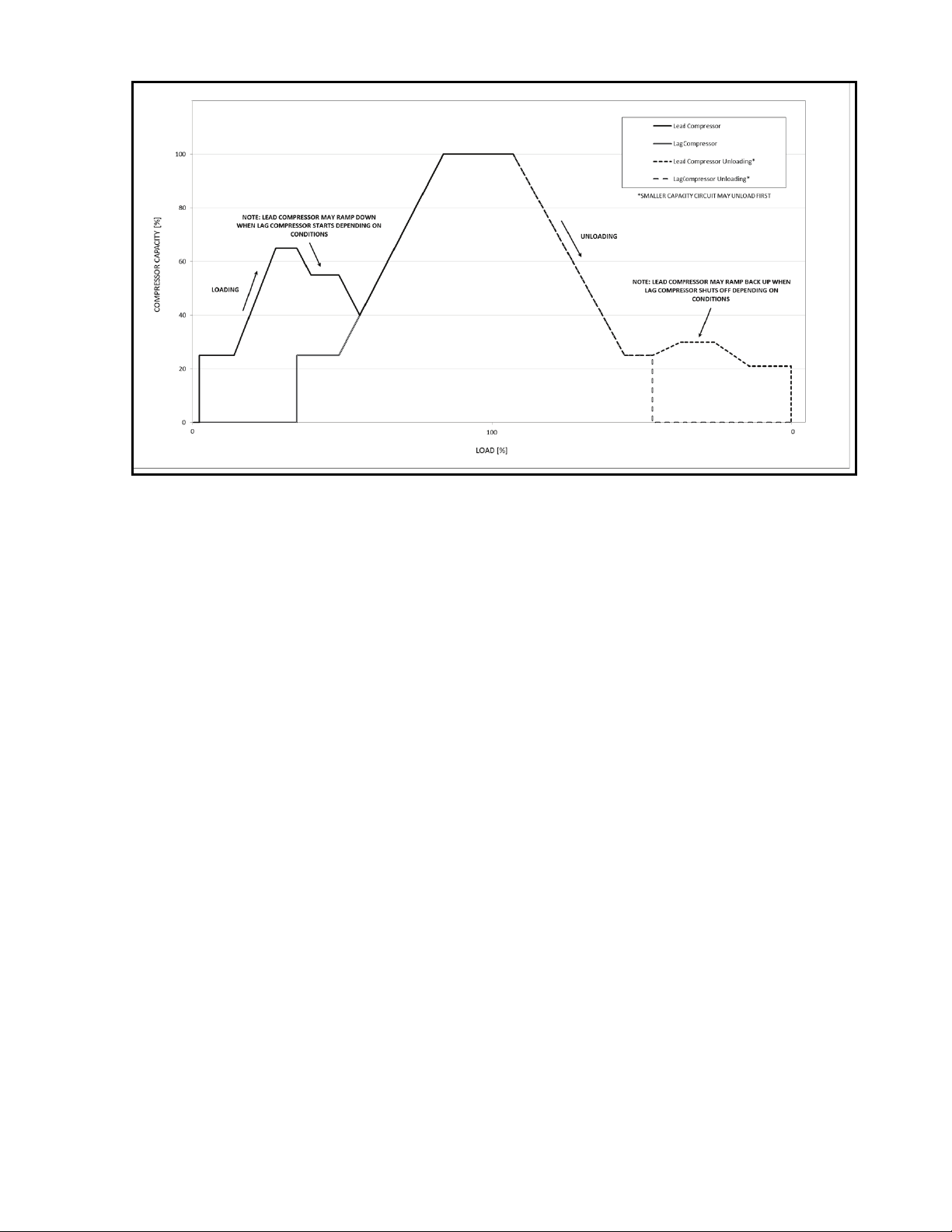
The CCN communication port for the Master and Slave
Fig. 24 — Initial Compressor Loading/Unloading Method
NOTE: After compressors are fully loaded, they will both load and unload
equally with the VFDs (variable frequency drives).
chillers must be joined using a shielded cable in order to avoid
communication issues.
The master/slave linkage will not be allowed to operate if
any one of the slave chiller CTRL_PNT, DEM_LIM,
LAG_LIM, or LCW_STPT variables has a force priority
higher than a control force. In that case, the master/slave operations will not be allowed or will be disabled.
The control algorithm relies on several parameters that must
be field configured for operation. Both chillers must be on the
same CCN bus with different addresses. On both chillers, Master/Slave Select (Main Menu Configuration Menu Master Slave config Master/Slave Select) must be enabled (set
to 1 or 2). The water piping arrangement must be specified
with the Chiller in Series variable (Main Menu Configuration Menu Master Slave config Chiller in Series). The
Master chiller must be programmed with the Slave Address
(Main Menu Configuration Menu Master Slave config
Slave Address). Additional optional programming parameters may be configured to meet application requirements.
The Lead Lag Select variable (Main Menu Configuration Menu Master Slave config Lead Lag Select) determines which chiller is the lead machine. The options are: Always Lead, Lag Once Failed Only, and Lead/Lag Runtime Select. Under Runtime Select control, the lead chiller will change
based on the time increment selected in the Lead/Lag Balance
Delta configuration (Main Menu Configuration Menu
Master Slave config Lead/Lag Balance Delta). If the run
hour difference between the master and the slave remains less
than the Lead/ Lag Balance Delta, the chiller designated as the
lead will remain the lead chiller. The Lead/Lag changeover between the master and the slave chiller due to hour balance will
occur during chiller operating odd days, such as day 1, day 3,
and day 5 of the month, at 12:00 a.m. If a lead chiller is not designated, the master chiller will always be designated the lead
chiller.
The dual chiller control algorithm has the ability to delay
the start of the lag chiller in two ways. The Lead Pulldown
Time parameter (Main Menu Configuration Menu Master Slave config Lead Pulldown Time) is a one-time time
delay initiated after starting the lead chiller, before checking
whether to start an additional chiller. This time delay gives the
lead chiller a chance to remove the heat that the chilled water
loop picked up while inactive during an unoccupied period.
The second time delay, Lead/Lag Start Timer (Main Menu
Configuration Menu Master Slave config Lead/Lag Start
Timer) is a time delay imposed between the last stage of the
lead chiller and the start of the lag chiller. This prevents enabling the lag chiller until the lead/lag delay timer has expired.
A quicker start of the lag chiller can be accomplished by
configuring the Lag Unit Pump Control parameter (Main
Menu Configuration Menu Master Slave config Lag
Unit Pump Control). If the difference between the common
leaving water temperature and the set point is greater than the
configured value, then the lag chiller will start.
A minimum on time for the lag chiller can be programmed with the Lag Minimum Running Time configuration (Main Menu Configuration Menu Master Slave
config Lag Minimum Running Time). This parameter
causes the control to run the lag chiller for the programmed
minimum On time. The Lag Unit Pump Control (Main
Menu Configuration Menu Master Slave config
Lag Unit Pump Control) can be configured such that the
pump can be on or off while the chiller is off. This parameter is only active in Parallel Chiller Operation.
The lead chiller is started first and the lag chiller will be
maintained at zero percent capacity through master forcing
the lag demand limit value (LAG_LIM) to 0%. The lag water pump will be maintained off. When the lead chiller cannot be loaded anymore (because it is loaded at its full available capacity or at the master demand limit value) then the
lag start timer is started. When the lag start time has
elapsed, if the error on the master controlled set point is
greater than the dead band (start_di) and if the pulldown
time is elapsed then the lag chiller water pump will be
turned on (if required by configuration) and the lag chiller
will be allowed to start through the master chiller forcing
the lag chiller demand limit value (LAG_LIM) to its own
demand limit value. To ensure that the lag chiller will be unloaded first in case of water load decrease, the lead chiller
27

set point error will be reset downwards by 4° F (2.2° C) provided that the lead capacity is not zero.
Each dual chiller application, Parallel and Series, is de-
scribed separately below.
DUAL CHILLER CONTROL FOR PARALLEL APPLI-
CATIONS — To configure the master chiller for parallel
applications, see Table 24. To configure the slave chiller for
parallel applications, see Table 25.
DUAL CHILLER PUMP CONTROL FOR PARALLEL
CHILLER APPLICATIONS — Parallel chiller control with
dedicated pumps is recommended. The chiller must start and
stop its own water pump located in its own piping. If pumps are
not dedicated for each chiller’s piping, chiller isolation valves
are required; each chiller must open and close its own isolation
valve through the control. Figures 25-28 show typical pump arrangements for dual chiller parallel applications.
Although not recommended, it is possible to configure the
system with no individual pump control. In applications where
the unit is configured for fresh water (Main Menu
Configuration Menu Service Parameters, Evaporator Fluid
Type=1 [Fresh Water]), and Set Point temperature is close to
the lower limit of the fresh water range, it is possible for
changeable leaving water conditions as the chilled water flow
rate drops to an operating unit, causing the leaving chilled water temperature to drop and initiate the evaporator freeze protection override. Constant flow applications may alleviate this
issue. In constant water flow applications, the master chiller
should be the primary control source for the chilled water
pump. The slave chiller should have override capability. In the
event of a communication failure between the master and slave
chillers, the slave chiller will operate as a stand-alone machine
and therefore must be able to enable the chilled water pump.
DUAL CHILLER CONTROL FOR SERIES CHILLER
APPLICATIONS — When chillers are configured to work
in series mode no additional chilled water supply sensor is
required. The master chiller will be installed downstream of
the slave chiller (the slave chiller outlet fluid is the master
inlet fluid). If pump control is required, it will be controlled
by the master chiller.
To configure the master chiller for series applications, see
Table 26. To configure the slave chiller for series applications,
see Table 27.
28
Table 24 — Dual Master Chiller Control Parameters for Parallel Applications
DISPLAY NAME PATH VALUE
Master/Slave Select
Master Control Type
Slave Address
Lead Lag Select
Lead/Lag Balance Delta
Lead/Lag Start Timer
Lead Pulldown Time
Start If Error Higher
Lag Minimum Running
Time
Lag Unit Pump Control
Chiller In Series
Main Menu
Configuration Menu Master Slave config
1 (Master)
Default: 0 (Disable)
1=Local Control
2=Remote Control
3=CCN Control
Default: 1(Local)
Configure for proper control type.
Must be set to the Slave Chiller’s address. The
Master and Slave chiller must have different
addresses and be on the same Bus Number
Default: 2
0 (Master Always Leads)
1 (Lag One Failed Only)
2 (Lead/Lag Runtime Select)
Default: 0 (Master Always Leads)
Range: 40 to 400 hours
Default: 168 hours
Range: 2 to 30 minutes
Default: 10 minutes
Range: 0 to 60 minutes
Default: 0 minutes
Range: 3.0 to 18 F (1.7 to 10.0 C)
Default: 4.0 F (2.2 C)
Range: 0 to 150 minutes
Default: 0 minutes
0 (Stop If Unit Stops)
1 (Run If Unit Stops)
Default: 0 (Stop If Unit Stops)
No (Not in Series)
Default: No
Table 25 — Dual Slave Chiller Control Parameters for Parallel Applications
DISPLAY NAME PATH VALUE
Master/Slave Select
Master Control Type
Slave Address
Lead Lag Select
Lead/Lag Balance Delta
Lead/Lag Start Timer
Lead Pulldown Time
Start If Error Higher
Lag Minimum Running Time
Lag Unit Pump Control
Chiller In Series
NOTE: If pump control is configured to OFF (Master), then Lag Unit
(Slave) Pump Control= 1. If pump control is set to any other value, then
Main Menu
Configuration Menu Master Slave config
Lag Unit (Slave) Pump Control = 0. This configuration must be set consistently for both master and slave chillers.
2 (Slave)
Default: 0 (Disable)
1=Local Control
2=Remote Control
3=CCN Control
Default: 1(Local)
Configure for proper control type.
Must be set to the Slave Chiller’s address. The
master and slave chiller must have different
addresses and be on the same Bus Number
Default: 2
0 (Master Always Leads)
1 (Lag Once Failed Only)
2 (Lead/Lag Runtime Select)
Default: 0 (Master Always Leads)
Range: 40 to 400 hours
Default: 168 hours
Range: 2 to 30 minutes
Default: 10 minutes
Range: 0 to 60 minutes
Default: 0 minutes
Range: 3.0 to 18 F (1.7 to 10.0 C)
Default: 4.0 F (2.2 C)
Range: 0 to 150 minutes
Default: 0 minutes
0 (Stop If Unit Stops)
1 (Run If Unit Stops)
Default: 0 (Stop If Unit Stops)
No (Not in Series)
Default: No
29
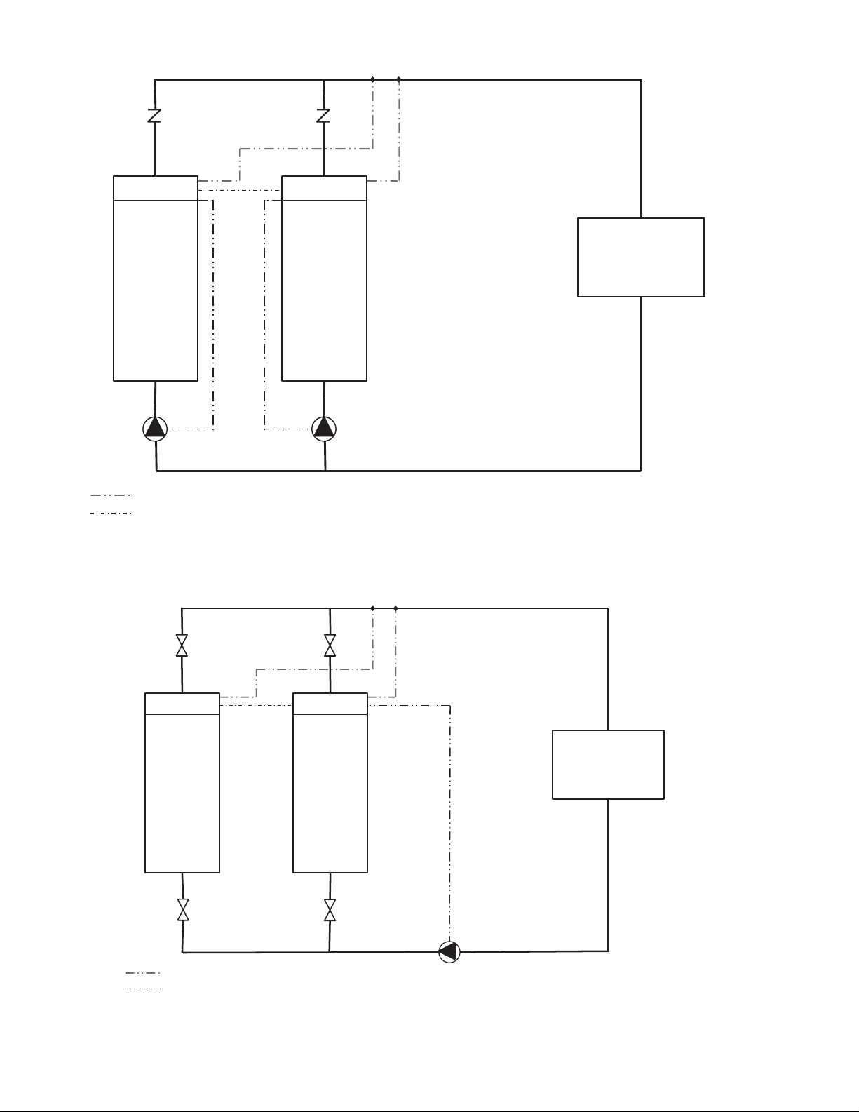
Fig. 25 — Typical Parallel Master/Slave Chillers
Dedicated Primary Pumping, Variable Flow, Leaving Water Control
CONTROL BOX
SLAVE
CHILLER
CONTROL BOX
MASTER
CHILLER
LOAD
CHECK VALVES
CHWS TEMP SENSORS
FIELD WIRING
FIELD COMMUNICATION WIRING
SLAVE
PUMP
MASTER
PUMP
NOTE: This is a simplified wiring diagram.
Not all hydronic specialties are shown.
Fig. 26 — Typical Parallel Master/Slave Chillers
Common Primary Pumping, Constant Flow, Leaving Water Control
CHWS TEMP SENSORS
ISOLATION VALVES
CONTROL BOX
SLAVE
CHILLER
ISOLATION VALVES
FIELD WIRING
FIELD COMMUNICATION WIRING
CONTROL BOX
MASTER
CHILLER
LOAD
MASTER
PUMP
NOTE: This is a simplified wiring diagram.
Not all hydronic specialties are shown.
30
Loading...