


30XA080-500
Air-Cooled Liquid Chillers
Installation Instructions
AQUAFORCE
30XA080-500
®
CONTENTS
Page
SAFETY CONSIDERATIONS . . . . . . . . . . . . . . . . . . . . . . 1
INTRODUCTION . . . . . . . . . . . . . . . . . . . . . . . . . . . . . . . . . . 1
INSTALLATION . . . . . . . . . . . . . . . . . . . . . . . . . . . . . . . . 1-78
Storage . . . . . . . . . . . . . . . . . . . . . . . . . . . . . . . . . . . . . . . . . . 1
Step 1 — Inspect Shipment . . . . . . . . . . . . . . . . . . . . . . 1
Step 2 — Place, Mount and Rig Unit. . . . . . . . . . . . . 2
•PLACING UNIT
• MOUNTING UNIT
• RIGGING UNIT
Step 3 — Cooler Fluid and Drain Piping
Connections . . . . . . . . . . . . . . . . . . . . . . . . . . . . . . . . . . 41
• GENERAL
• UNITS WITH A HYDRONIC PUMP PACKAGE
• UNITS WITHOUT A HYDRONIC PUMP PACKAGE
• DUAL CHILLER CONTROL
• COOLER PUMP CONTROL
• BRINE UNITS
• PREPARATION FOR YEAR-ROUND OPERATION
Step 4 — Fill the Chilled Water Loop . . . . . . . . . . . . 56
• WATER SYSTEM CLEANING
• WATER TREATMENT
• SYSTEM PRESSURIZATION
• FILLING THE SYSTEM
• SET WATER FLOW RATE
• PUMP MODIFICATION/TRIMMING
• FREEZE PROTECTION
• PREPARATION FOR WINTER SHUTDOWN
Step 5 — Make Electrical Connections . . . . . . . . . . 62
• POWER SUPPLY
• FIELD POWER CONNECTIONS
•POWER WIRING
• FIELD CONTROL POWER CONNECTIONS
• CARRIER COMFORT NETWORK®
COMMUNICATION BUS WIRING
• NON-CCN COMMUNICATION WIRING
• FIELD CONTROL OPTION WIRING
• DUAL CHILLER LEAVING WATER SENSOR
Step 6 — Install Accessories . . . . . . . . . . . . . . . . . . . . 77
• ENERGY MANAGEMENT MODULE
• REMOTE ENHANCED DISPLAY
• LOW AMBIENT TEMPERATURE OPERATION
• MINIMUM LOAD ACCESSORY
• UNIT SECURITY/PROTECTION ACCESSORIES
• COMMUNICATION ACCESSORIES
• SERVICE OPTIONS
• CONTROL TRANSFORMER
Step 7 — Leak Test Unit . . . . . . . . . . . . . . . . . . . . . . . . . 77
Step 8 — Refrigerant Charging. . . . . . . . . . . . . . . . . . 77
• DEHYDRATION
• REFRIGERANT CHARGE
SAFETY CONSIDERATIONS
Installing, starting up, and servicing this equipment can be
hazardous due to system pressures, electrical components, and
equipment location. Only trained, qualified installers and service
mechanics should install, start up, and service this equipment.
When working on the equipment, observe precautions in the
literature, and on tags, stickers, and labels attached to the
equipment.
• Follow all safety codes.
• Wear safety glasses and work gloves.
• Use care in handling, rigging, and setting bulky equipment.
WARNING
Electrical shock can cause personal injury and death. Shut
off all power to this equipment during installation. There
may be more than one disconnect switch. Tag all disconnect locations to alert others not to restore power until work
is completed.
IMPORTANT: This equipment generates, uses, and
can radiate radio frequency energy and if not installed
and used in accordance with these instructions may
cause radio interference. It has been tested and found
to comply with the limits of a Class A computing
device as defined by FCC (Federal Communications
Commission, U.S.A.) regulations, Subpart J of Part 15,
which are designed to provide reasonable protection
against such interference when operated in a commercial environment.
INTRODUCTION
These instructions cover installation of 30XA080-500 aircooled liquid chillers with electronic controls and units with
factory-installed options (FIOPs). See Fig. 1.
INSTALLATION
Storage —
fore installation or start-up, be sure to protect the machine
from construction dirt. Keep protective shipping covers in
place until the machine is ready for installation.
If the unit is to be stored for a period of time be-
Step 1 — Inspect Shipment — Inspect unit for dam-
age upon arrival. If damage is found, immediately file a claim
with the shipping company, and contact your local Carrier
representative.
Manufacturer reserves the right to discontinue, or change at any time, specifications or designs without notice and without incurring obligations.
Catalog No. 04-53300026-01 Printed in U.S.A. Form 30XA-10SI Pg 1 11-09 Replaces: 30XA-5SI

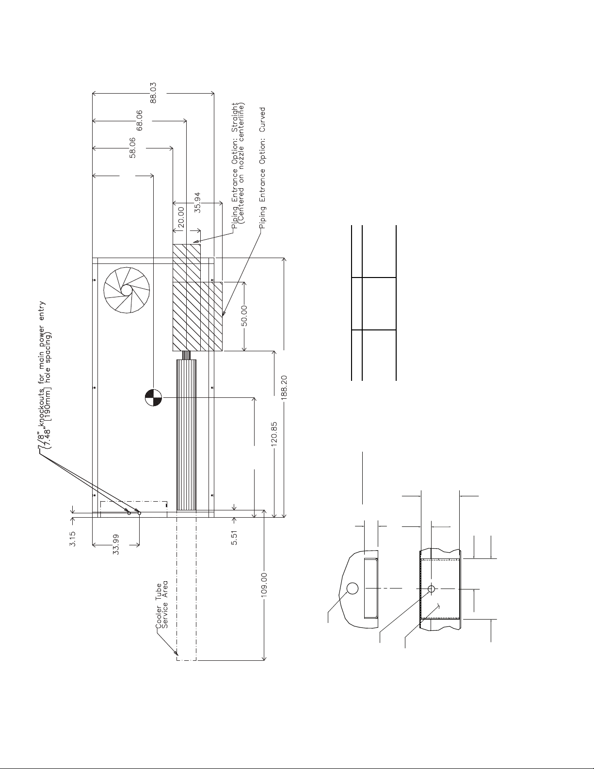
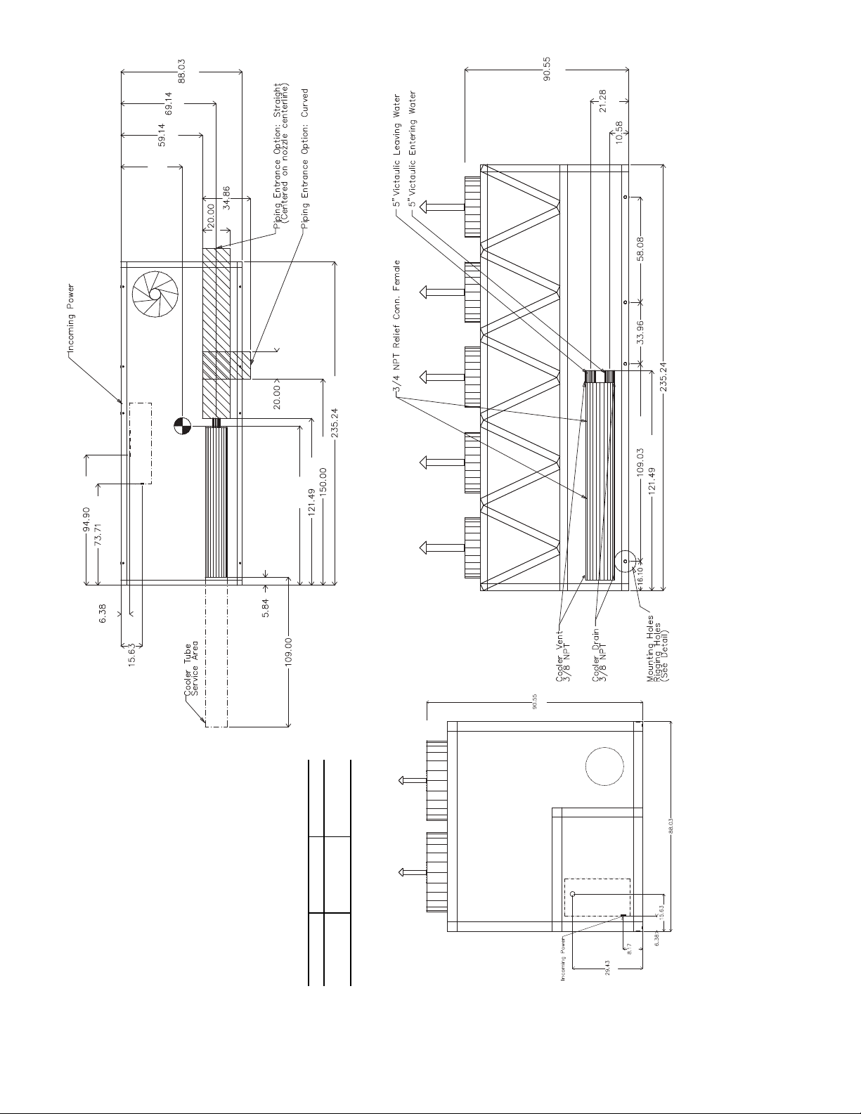
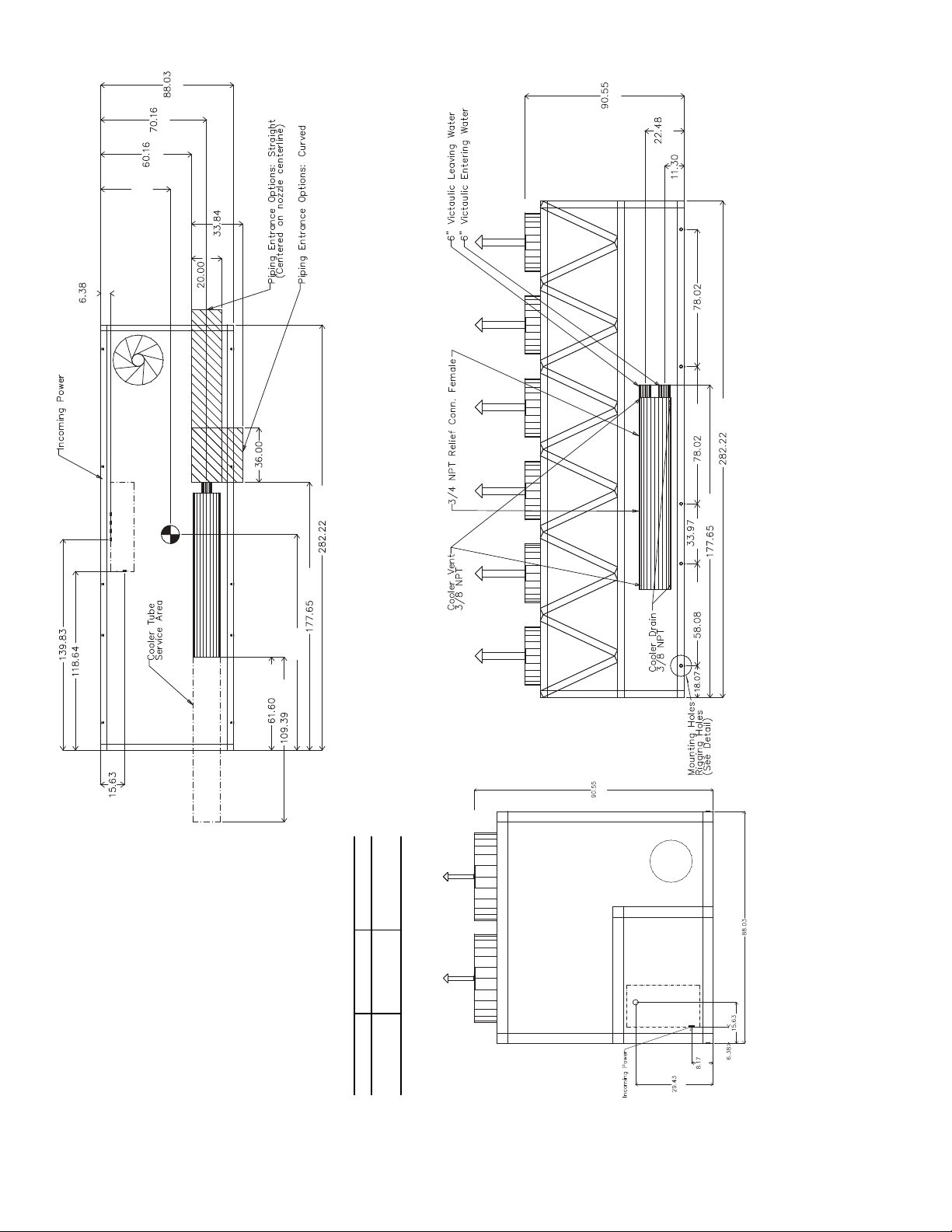
Step 2 — Place, Mount, and Rig the Unit —
When considering a location for the unit, be sure to consult
NEC (National Electrical Code, U.S.A.) and/or local code
requirements. Allow sufficient space for airflow, wiring, piping, and service. See Fig. 2-14.
NOTE: To facilitate refrigerant vent piping, all units have fusible plugs with
flares and pressure reliefs with 3/4 in. NPT fittings (if required
by local codes).
PLACING UNIT — Locate the unit so that the condenser
airflow is unrestricted both above and on the sides of the unit.
Airflow and service clearances are 6 ft (1.8 m) around the unit.
Acceptable clearance on the sides or ends without control boxes
can be reduced to 3 ft (1 m) without sacrificing performance as
long as the remaining three sides are unrestricted. Acceptable
clearance on the side with a control box can be reduced to 4 ft
(1.3 m) due to NEC regulations, without sacrificing performance
as long as the remaining three sides are unrestricted. Provide ample room for servicing and removing the cooler. See Fig. 2-14 for
required clearances. Local codes for clearances take precedence
1
/4 in. SAE (Society of Automotive Engineers)
over the manufacturer’s recommendations when local codes call
for greater clearances.
If multiple units are installed at the same site, a separation of
10 ft (3 m) between the sides of the machines is required to
maintain proper airflow and minimize the chances of condenser air recirculation.
MOUNTING UNIT — The unit may be mounted on a level
pad directly on the base rails, on a raised mounting rail around
the unit, or on vibration isolation springs. For all units, ensure
placement area is strong enough to support unit operating
weight. See Tables 1A and 1B. Mounting holes are provided
for securing the unit to the pad, mounting rail or vibration
isolation springs. Bolt the unit securely to pad or rails. If vibration isolators (field-supplied) are required for a particular
installation, refer to unit weight distribution in Fig. 15A-15C to
aid in the proper selection of isolators. The 30XA units can be
mounted directly on spring isolators. Once installed, the unit
must be level to within
1
/8-in. per ft (1 cm per meter) along the
long axis of the oil separator. This is required for oil return to
the compressor(s).
2
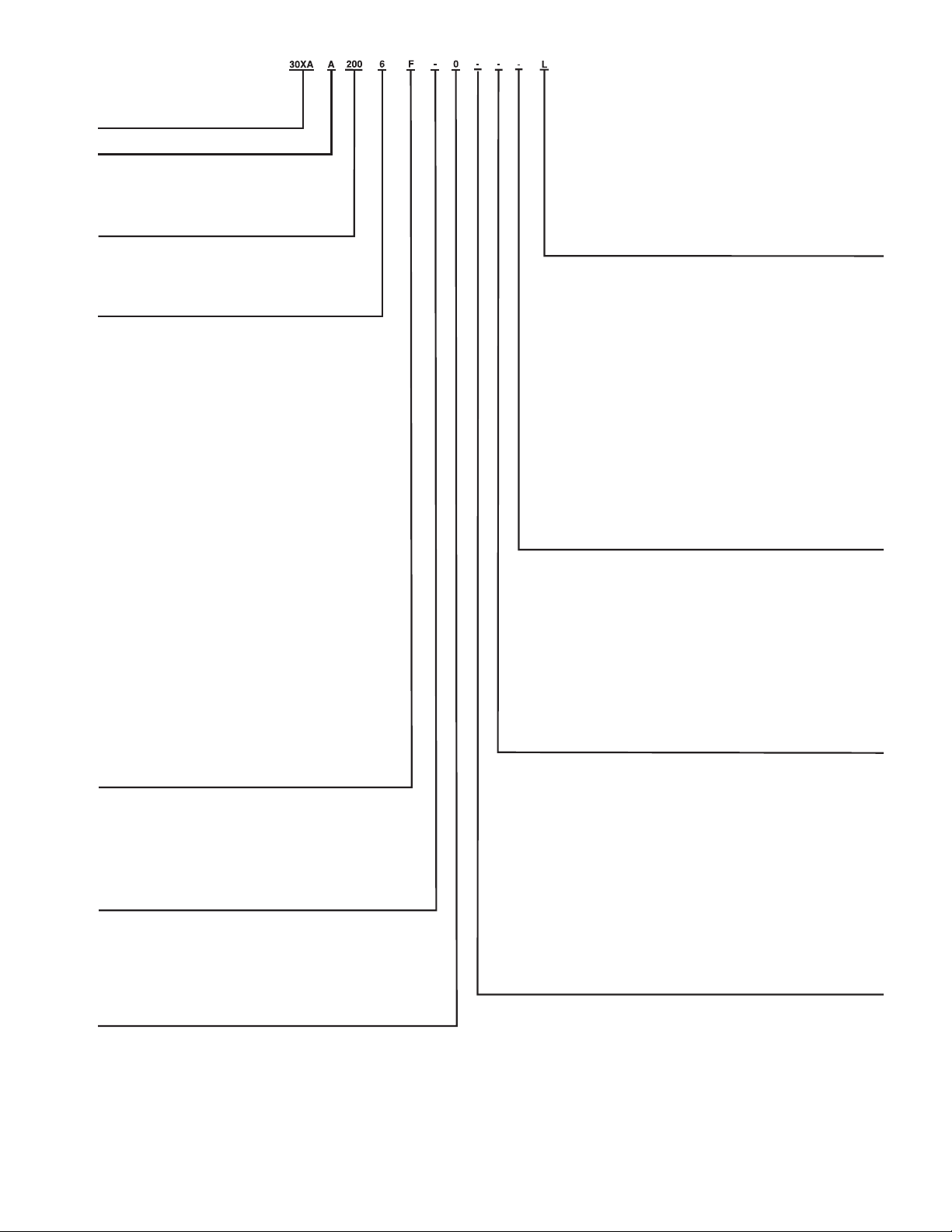
Fig. 1 — AquaForce® Chiller Model Number Designation
a30-4401
LEGEND
CFSP — Coil Face Shipping Protection
EMM — Energy Management Module
LON — Local Operating Network
MCHX — Microchannel Heat Exchanger
XL — Across-the-Line Starter
30XA – AquaForce® Air-Cooled Chiller
Quality Assurance
Certified to ISO 9001:2000
Design Series
Unit Sizes
080 140 240 350
090 160 260 400
100 180 280 450
110 200 300 500
120 220 325
Voltage
1 – 575-3-60
2 – 380-3-60
4 – 230-3-60
6 – 460-3-60
7 – 200-3-60
Condenser Coil/Ambient/Low Sound Options
- – Aluminum Fin/Copper Tube, High Ambient Temperature
0 – Copper Fin/Copper Tube, High Ambient Temperature
1 – Aluminum Pre-Coat Fin/Copper Tube, High Ambient Temperature
2 – Aluminum E-Co
3 – Copper E-Coat Fin/Copper Tube, High Ambient Temperature
4 – Novation® Heat Exchanger (MCHX), High Ambient
Temperature
5 – MCHX E-Coat, High Ambient Temperature
6 – Aluminum Fin/Copper Tube, High Ambient Temperature,
Low Sound
7 – Copper Fin/Copper Tube, High Ambient Temperature, Low Sound
8 – Aluminum Pre-Coat Fin/Copper Tube, High Ambient Temperature,
Low Sound
9 – Aluminum E-Coat Fin/Copper Tube, High Ambient Temperature,
Low Sound
B – Copper E-Coat Fin/Copper Tube, High Ambient Temperature,
Low Sound
C – MCHX, High Ambient Temperature, Low Sound
D – MCHX E-Coat, High Ambient Temperature, Low Sound
F – Aluminum Fin/Copper Tube, Standard Ambient Temperature,
Low Sound
G – Copper Fin/Copper Tube, Standard Ambient Temperature,
Low Sound
H – Aluminum Pre-Coat Fin/Copper Tube, Standard Ambient
Temper
J – Aluminum E-Coated Fin/Copper Tube, Standard Ambient
Temperature, Low Sound
K – Copper E-Coat Fin/Copper Tube, Standard Ambient Temperature,
Low Sound
L – MCHX, Standard Ambient Temperature, Low Sound
M – MCHX E-Coat, Standard Ambient Temperature, Low Sound
N – Aluminum Fin/Copper Tube, Standa
P – Copper Fin/Copper Tube, Standard Ambient Temperature
Q – Aluminum Pre-Coat Fin/Copper Tube, Standard Ambient
Temperature
R – Aluminum E-Coat Fin/Copper Tube, Standard Ambient
Temperature
S – Copper E-Coat Fin/Copper Tube, Standard Ambient Temperature
T – MCHX, Standard Ambient Temperature
V – MCHX E-Coat, Standard Ambient Temperat
Hydronic Pump Package Options
- – None
1 – Single Pump, 5 HP
2 – Single Pump, 7.5 HP
3 – Single Pump, 10 HP
4 – Single Pump, 15 HP
7 – Dual Pump, 5 HP
8 – Dual Pump, 7.5 HP
B – Dual Pump, 10 HP
C – Dual Pump, 15 HP
Cooler/Brine Options
0 – Integral Cooler with Heater
3 – Integral Cooler with Heater, Minus One Pass
5 – Integral Cooler with Heater, Plus One Pass
7 – Integral Cooler with Heater, Full End Screen
H – Integral Cooler with Heater, Plus One Pass, Brine
K – Integral Cooler with Heater, Minus One Pass, Full End Screen
M – Integral Cooler with Heater, Plus One Pass, Full End Screen
V – Integral Cooler with Heater, Plus One Pass, Brine, Full End Screen
at Fin/Copper Tube, High Ambient Temperature
ature, Low Sound
rd Ambient Temperature
ure
Packaging/Security Options
0 – Coil Fa
1 – CFSP, Skid, Top Crate, Bag
3 – CFSP, Coil Trim Panels
4 – CFSP, Skid, Coil Trim Panels
5 – CFSP, Skid, Top Crate, Bag, Coil Trim Panels
7 – CFSP, Coil Trim Panels, Upper and Lower Grilles
8 – CFSP, Skid, Coil Trim Panels, Upper and Lower Grilles
9 – CFSP, Skid, Top Crate, Bag, Coil Trim Panels, Upper and Lower Grilles
C – CFSP, Trim Panels, Upper and Lower Grilles, Upper Hail G
D – CFSP, Skid, Coil Trim Panels, Upper and Lower Grilles, Upper Hail Guards
F – CFSP, Skid, Top Crate, Bag, Trim Panels, Upper and Lower Grilles,
Upper Hail Guards
L – CFSP
Controls/Communication Options
- – Navigator™ Display
0 – Navigator Display, EMM
1 – Navigator Display, Service Option
2 – Navigator Display, EMM, Service Option
3 – Tou
4 – Touch Pilot Display, EMM
5 – Touch Pilot Display, Service Option
6 – Touch Pilot Display, EMM, Service Option
7 – Navigator Display, BACnet Translator
8 – Navigator Display, BACnet Translator, EMM
9 – Navigator Display, BACnet Translator, Service Option
B – Navigator Display, BACnet Translator, EMM, Service Option
C – Touch Pilot Display, BACnet Translator
D – Touch Pilot Display, BACnet Translator, EMM
F – Touch Pilot Display, BACnet Translator, Service Option
G – Touch Pilot Display, BACnet Translator, EMM, Service Option
H – Navigator Display, LON Translator
J – Navigator Display, LON Translator, EMM
K – Navigator Displa
L – Navigator Display, LON Translator, EMM, Service Option
M – Touch Pilot Display, LON Translator
N – Touch Pilot Display, LON Translator, EMM
P – Touch Pilot Display, LON Translator, Service Option
Q – Touch Pilot Display, LON Translator, EMM, Service Option
Electrical Options
- – Single Point Power, XL, Terminal Block, No Control Transformer
0 –
3 – Dual Point Power, XL, Terminal Block, No Control Transformer
4 – Dual Point Power, Wye-Delta, Terminal Block, No Control Transformer
7 – Single Point Power, XL, Disconnect, No Control Transformer
8 – Single Point Power, Wye-Delta, Disconnect, No Control Transformer
C – Dual Point Power, XL, Disconnect, No Control Transformer
D – Dual Point Power, Wye-Delta, Disconnect, No Control Transformer
H – Single Point Power, XL, Terminal Block, Control Transformer
J – Single Point Power, Wye-Delta, Terminal Block, Control Transformer
M – Dua
N – Dual Point Power, Wye-Delta, Terminal Block, Control Transformer
R – Single Point Power, XL, Disconnect, Control Transformer
S – Single Point Power, Wye-Delta, Disconnect, Control Transformer
W – Dual Point Power, XL, Disconnect, Control Transformer
X – Dual Point Power, Wye-Delta, Disconnect, Control Transformer
Refrigeration Circuit Options
- – None
0 – Suction Line Insulation
1 – Suction Service Valves
2 – Low Ambient Temperature Head Pressure Control
3 – Su
4 – Suction Line Insulation, Low Ambient Temperature Head Pressure Control
5 – Suction Service Valves, Low Ambient Temperature Head Pressure Control
6 – Suction Line Insulation, Suction Service Valves, Low Ambient Temperature
Head Pressure Control
7 – Minimum Load Control
8 – Suction Line Insulation, Minimum Load Control
9 – Suction Service Valves, Minimu
B – Low Ambient Temperature Head Pressure Control, Minimum Load Control
C – Suction Line Insulation, Suction Service Valves, Minimum Load Control
D – Suction Line Insulation, Low Ambient Temperature Head Pressure
Control, Minimum Load Control
F – Suction Service Valves, Low Ambient Temperature Head Pressure
Control, Minimum Load Control
G – Suction Line Insulation, Suction Service Valves, Low Ambient Temperature
Head Pressure Control, Minimum Load Control
ce Shipping Protection (CFSP), Skid
uards
ch Pilot™ Display
y, LON Translator, Service Option
Single Point Power, Wye-Delta, Terminal Block, No Control Transformer
l Point Power, XL, Terminal Block, Control Transformer
ction Line Insulation, Suction Service Valves
m Load Control
3
3.93
7.88
[200]
DETAIL "A"
MOUNTING PLATE
CONTACT SURFACE
TYPICAL 4 PLACES
[100]
MOUNTING HOLE
0.875 DIA.[22.2]
MOUNTING
PLATE
1.50 DIA. [38.1]
RIGGING HOLE
[127]
5.0
[33]
1.31
1.75
[44]
[1114]
[1729]
[2236]
[508]
[1670]
[3587]
[3078]
[148]
[2769]
[80]
[863]
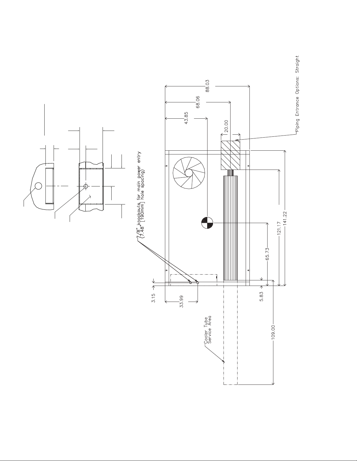
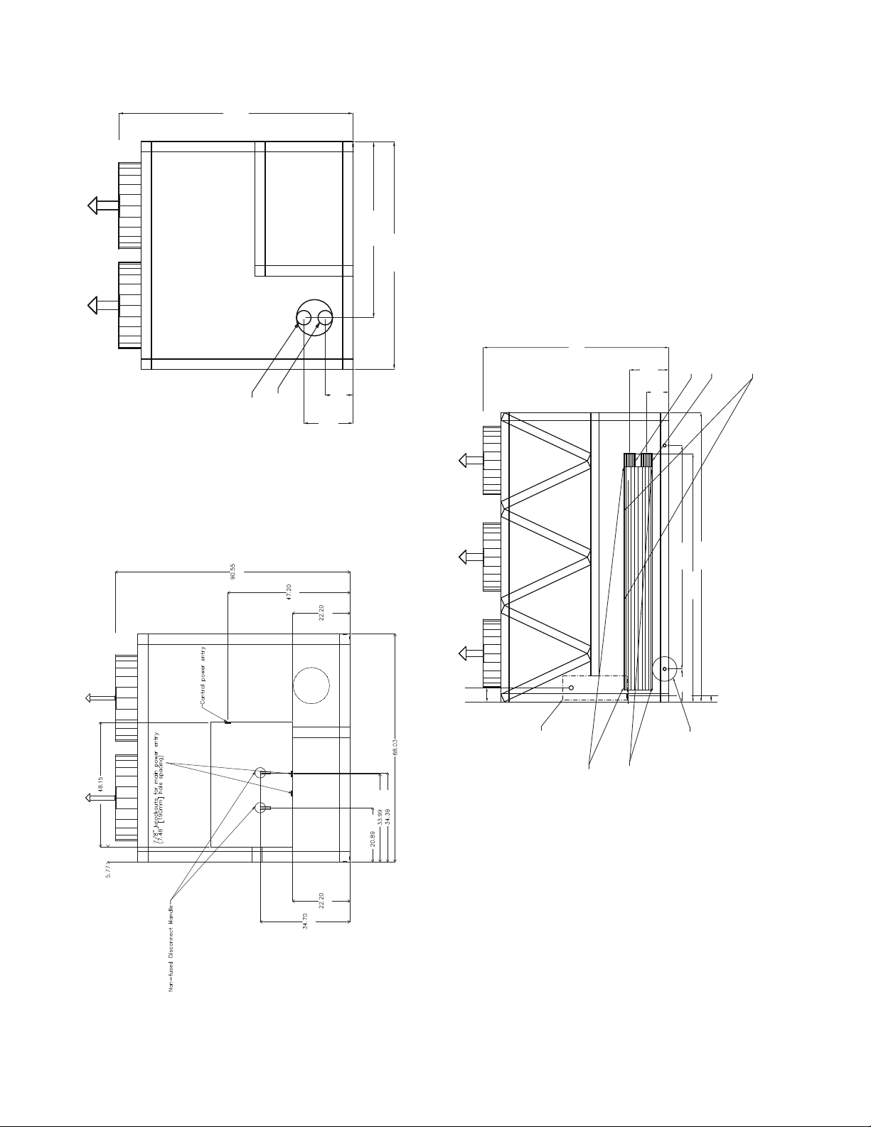
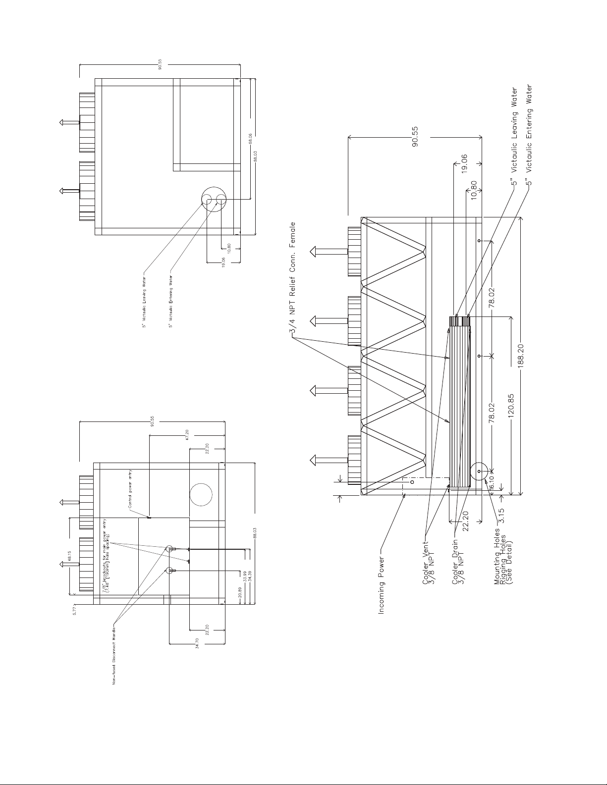
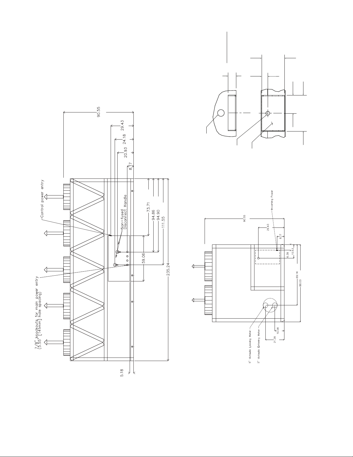
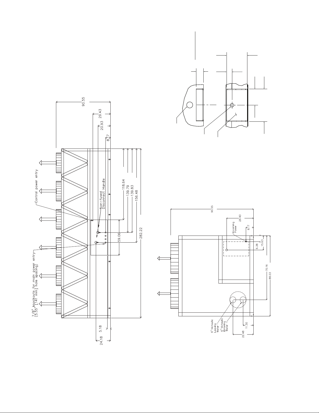
Fig. 2 — 30XA080 Air-Cooled Liquid Chiller Dimensions
NOTES:
1. Unit must have clearances as follows:
Top — Do not restrict
Sides and Ends — 6 ft (1.8 m) from solid surface.
2. Temperature relief devices are located on liquid line and econo-
mizer assemblies and have
1
/
4
-in. flare connection.
3.
3
/
8
-in. NPT vents and drains located in each cooler head at each
end of cooler.
4. Drawing depicts unit with single point power and standard two-
pass cooler. Refer to the Packaged Chiller Builder program for
other configurations.
5. Dimensions are shown in inches. Dimensions in [ ] are in
millimeters.
6. Allow 8 ft (2.4 m) on either side of unit for condenser coil removal.
a30-4402
TOP VIEW
4
5" Victaulic Entering Water
5" Victaulic Leaving Water
90.55
[2300]
19.06
[484]
10.8
[274]
88.04
[2236]
68.06
[1729]
[1223]
[147]
[2300]
[1199]
[564]
[2236]
[863]
[874]
[531]
[564]
[881]
8.8
[224]
3/4 NPT Relief
Conn. Female
5" Victaulic
Entering Water
5" Victaulic
Leaving Water
Cooler Vent
3/8 NPT
Cooler Drain
3/8 NPT
Mounting Holes
Rigging Holes
(See Detail A)
90.55
[2300]
19.06
[484]
10.8
[274]
141.22
[3587]
121.17
[3078]
109.03
[2769]
16.1
[409]
3.15
[80]
a30-4403
LEFT END VIEW
RIGHT END VIEW
FRONT VIEW
Fig. 2 — 30XA080 Air-Cooled Liquid Chiller Dimensions (cont)
5
A
[1475]
[1729]
[2236]
[913]
[508]
[1270]
[4780]
[3070]
B
[140]
[2769]
[80]
[863]
NOTES:
1. Unit must have clearances as follows:
Top — Do not restrict
Sides and Ends — 6 ft (1.8 m) from solid surface.
2. Temperature relief devices are located on liquid line and economizer assem-
blies and have
1
/
4
-in. flare connection.
3.
3
/
8
-in. NPT vents and drains located in each cooler head at each end of cooler.
4. Drawing depicts unit with single-point power and standard two-pass cooler.
Refer to the Packaged Chiller Builder program for other configurations.
5. Dimensions are shown in inches. Dimensions in [ ] are in millimeters.
6. Allow 8 ft (2.4 m) on either side of unit for condenser coil removal.
30XA UNIT A B
090 44.11 [1120] 86.93 [2208]
100 44.11 [1120] 87.22 [2215]
110 44.11 [1120] 87.62 [2226]
120 44.11 [1120] 87.12 [2213]
a30-4404
3.93
7.88
[200]
DETAIL "A"
MOUNTING PLATE
CONTACT SURFACE
TYPICAL 4 PLACES
[100]
MOUNTING HOLE
0.875 DIA.[22.2]
MOUNTING
PLATE
1.50 DIA. [38.1]
RIGGING HOLE
[127]
5.0
[33]
1.31
1.75
[44]
TOP VIEW
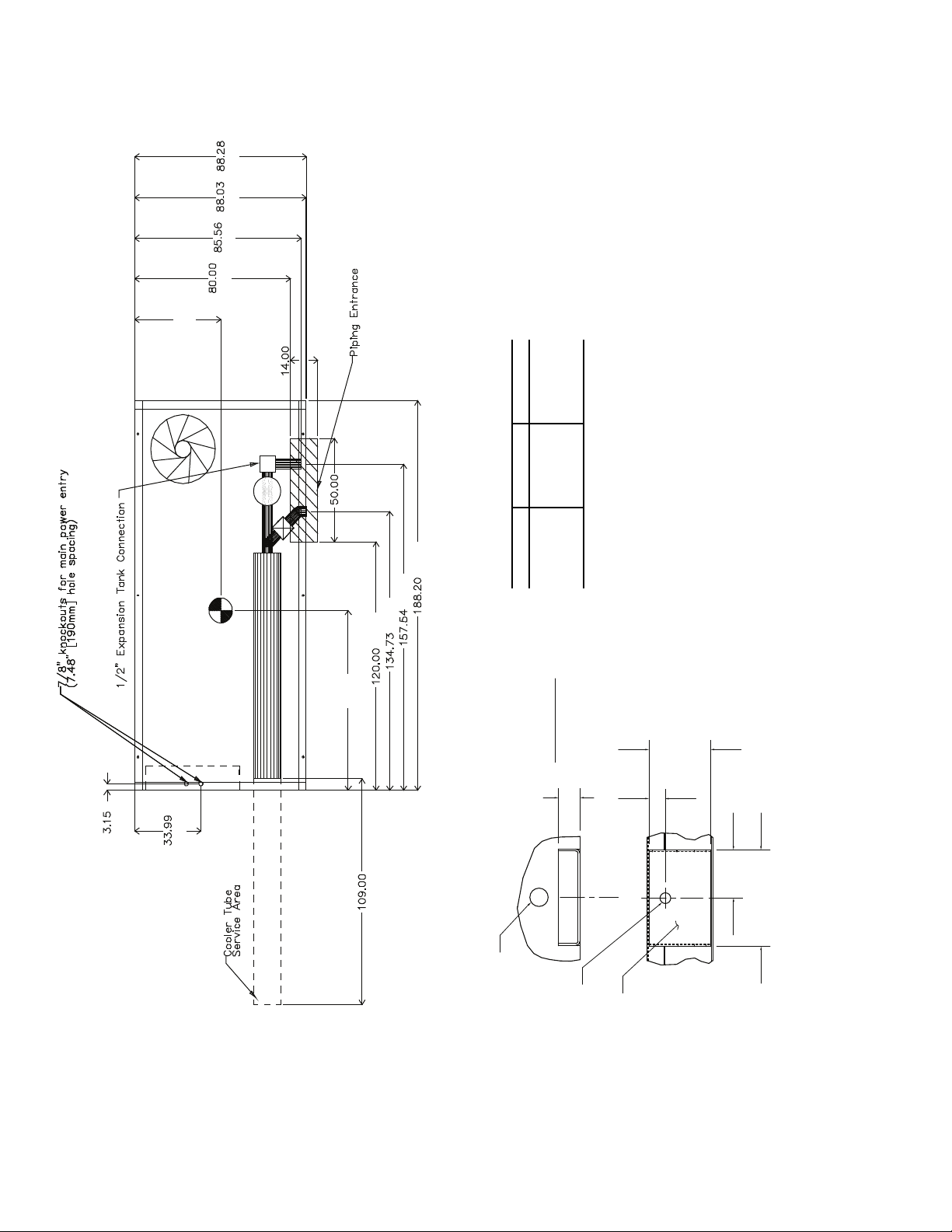
Fig. 3 — 30XA090-120 Air-Cooled Liquid Chiller without Pump Dimensions
6
[2300]
[484]
[274]
[1982]
[4780]
[1982]
[3070]
[80]
[564]
[409]
8.8
[224]
a30-4405
RIGHT END VIEWLEFT END VIEW
FRONT VIEW
Fig. 3 — 30XA090-120 Air-Cooled Liquid Chiller without Pump Dimensions (cont)
[2300]
[1729]
[2236]
[274]
[484]
[1223]
[147]
[2300]
[1199]
[564]
[564]
[881]
[874]
[863]
[531]
[2236]
7
[2242]
NOTES:
1. Unit must have clearances as follows:
Top — Do not restrict
Sides and Ends — 6 ft (1.8 m) from solid surface.
2. Temperature relief devices are located on liquid line and economizer assem-
blies and have
1
/
4
-in. flare connection.
3.
3
/
8
-in. NPT vents and drains located in each cooler head at each end of cooler.
4. Drawing depicts unit with single-point power and standard two-pass cooler.
Refer to the Packaged Chiller Builder program for other configurations.
5. Dimensions are shown in inches. Dimensions in [ ] are in millimeters.
6. Allow 8 ft (2.4 m) on either side of unit for condenser coil removal.
30XA UNIT A B
090 44.11 [1120] 86.93 [2208]
100 44.11 [1120] 87.22 [2215]
110 44.11 [1120] 87.62 [2226]
120 44.11 [1120] 87.12 [2213]
a30-4404
TOP VIEW
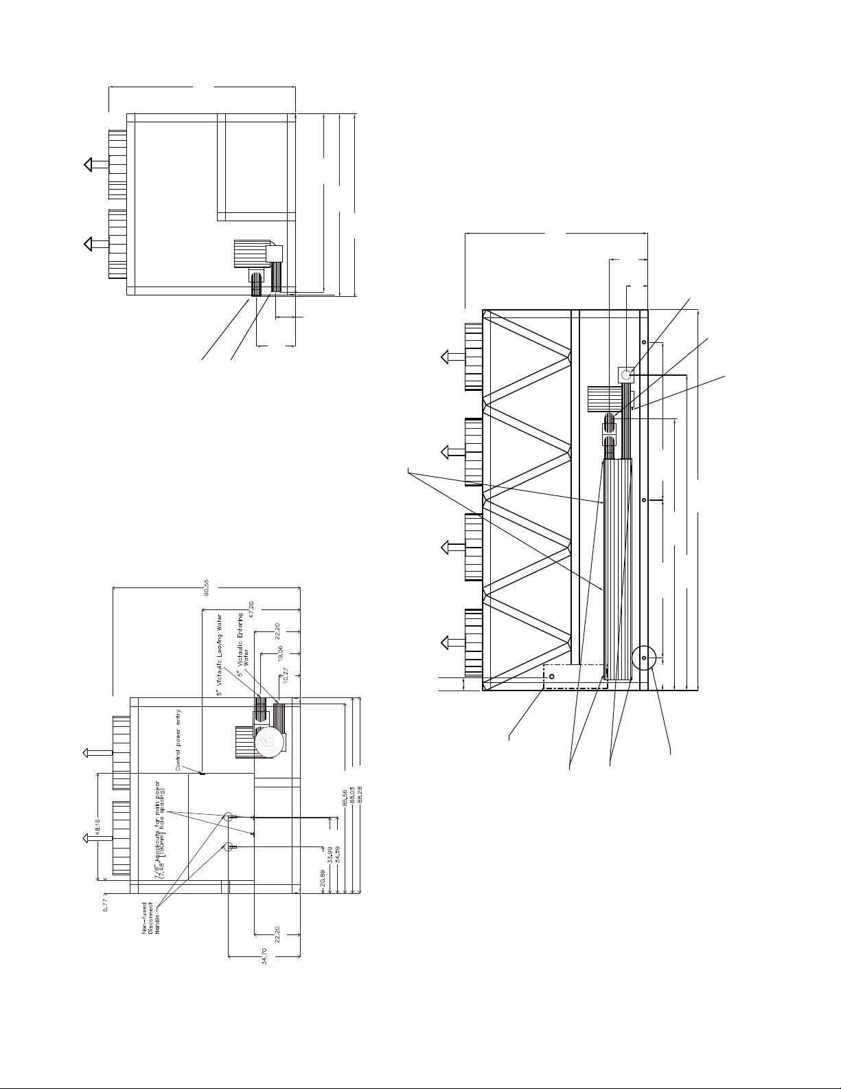
Fig. 4 — 30XA090-120 Air-Cooled Liquid Chiller with Pump Dimensions
[2236]
[2173]
[2032]
A
[356]
[1270]
[4780]
[80]
[863]
[4002]
[3422]
[3048]
B
[2769]
1.75
DETAIL "A"
[44]
MOUNTING PLATE
CONTACT SURFACE
TYPICAL 4 PLACES
[33]
1.31
5.0
[127]
3.93
[100]
7.88
[200]
1.50 DIA. [38.1]
RIGGING HOLE
MOUNTING
0.875 DIA.[22.2]
PLATE
MOUNTING HOLE
8
90.55
[2300]
19.06
[484]
10.27
[261]
88.04
[2236]
88.28
[2242]
85.56
[2173]
5" Victaulic Leaving Water
90.55
a30-4405
LEFT END VIEW
RIGHT END VIEW
FRONT VIEW
Fig. 4 — 30XA090-120 Air-Cooled Liquid Chiller with Pump Dimensions (cont)
[2300]
[484]
19.06
[2300]
[1199]
[564]
[484]
[261]
5" Victaulic Entering Water
5" Victaulic Leaving Water
Drain
in
[261]
10.27
3/4 NPT Relief Conn. Female
78.02
[1982]
188.2
[4780]
[3422]
134.73
[4002]
157.54
78.02
[1982]
16.1
8.8
[224]
[409]
[1223]
[147]
[881]
[564]
[531]
[863]
[874]
[2173]
[2236]
[2242]
Cooler Vent
3/8 NPT
Cooler Drain
3/8 NPT
Control Box All Voltages
Mounting Holes
Rigging Holes
(See Detail A)
9
[2300]
[541]
[269]
[5975]
[1475]
[863]
[3086]
[2769]
[409]
[2410]
[1872]
[162]
[397]
[148]
[2769]
[508]
B
[3086]
[3810]
[5975]
[508]
[885]
[2236]
[1756]
[1502]
A
NOTES:
1. Unit must have clearances as follows:
Top — Do not restrict
Sides and Ends — 6 ft (1.8 m) from solid
surface.
2. Temperature relief devices are located on
liquid line and economizer assemblies and
have
1
/
4
-in. flare connection.
3.
3
/
8
-in. NPT vents and drains located in
each cooler head at each end of cooler.
4. Drawing depicts unit with single-point
power, standard two-pass cooler, and
nominal voltage range of 380 to 575 v.
Refer to the Packaged Chiller Builder pro-
gram for other configurations.
5. Dimensions are shown in inches. Dimen-
sions in [ ] are in millimeters.
6. Allow 8 ft (2.4 m) on either side of unit for
condenser coil removal.
30XA UNIT A B
140 44.63 [1134] 115.88 [2943]
160 44.61 [1133] 115.64 [2937]
a30-4404
TOP VIEW
FRONT VIEW
LEFT END VIEW
[2300]
[2236]
[748]
[208]
[162]
[397]
Fig. 5 — 30XA140,160 Air-Cooled Liquid Chiller without Pump Dimensions
10
a30-4407
DETAIL "A"
BACK VIEW
RIGHT END VIEW
Fig. 5 — 30XA140,160 Air-Cooled Liquid Chiller without Pump Dimensions (cont)
MOUNTING PLATE
CONTACT SURFACE
TYPICAL 4 PLACES
5.0
[127]
[2300]
[748]
[614]
[532]
[208]
[1872]
[2409]
[2410]
[2833]
[44]
1.75
1.50 DIA. [38.1]
RIGGING HOLE
[33]
1.31
MOUNTING
0.875 DIA.[22.2]
MOUNTING HOLE
[2300]
3.93
[100]
7.88
[200]
PLATE
[748]
[208]
[132]
[1500]
[5975]
[269]
[541]
[162]
[397]
[1756]
[2236]
11
A
[2032]
[2174]
[2236]
[2270]
[356]
[1270]
[2769]
[397]
[162]
[1872]
[2410]
[5975]
[4162]
[3431]
[3048]
B
90.55
a30-4407
TOP VIEW
FRONT VIEW
LEFT END VIEW
NOTES:
1. Unit must have clearances as follows:
Top — Do not restrict
Sides and Ends — 6 ft (1.8 m) from solid
surface.
2. Temperature relief devices are located on
liquid line and economizer assemblies and
have
1
/
4
-in. flare connection.
3.
3
/
8
-in. NPT vents and drains located in
each cooler head at each end of cooler.
4. Drawing depicts unit with single-point
power, standard two-pass cooler, and
nominal voltage range of 380 to 575 v.
Refer to the Packaged Chiller Builder pro-
gram for other configurations.
5. Dimensions are shown in inches. Dimen-
sions in [ ] are in millimeters.
6. Allow 8 ft (2.4 m) on either side of unit for
condenser coil removal.
30XA UNIT A B
140 44.63 [1134] 115.88 [2943]
160 44.61 [1133] 115.64 [2937]
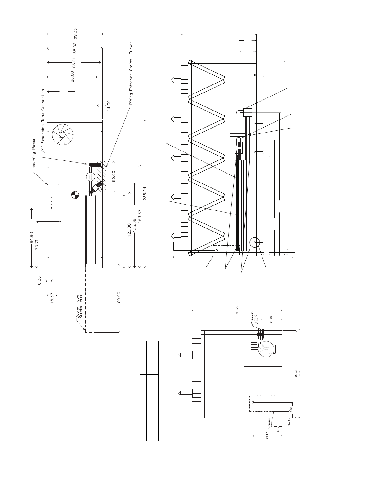
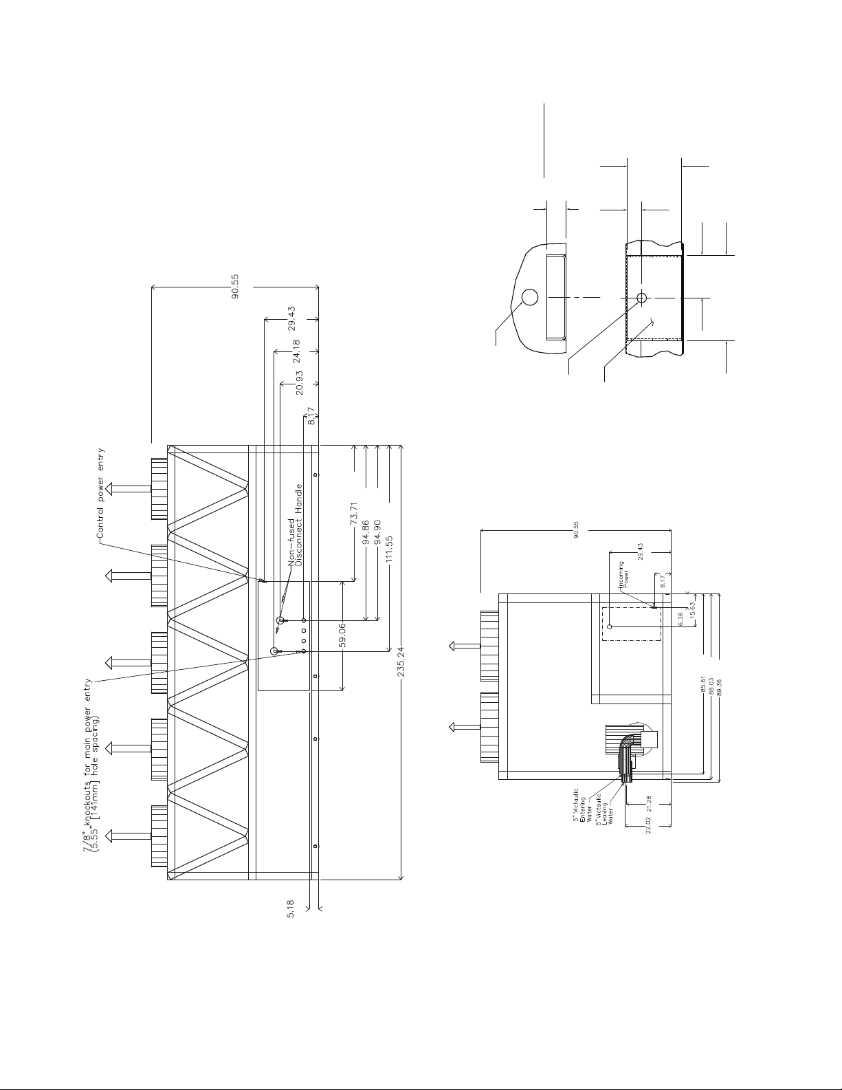
Fig. 6 — 30XA140,160 Air-Cooled Liquid Chiller with Pump Dimensions
[2300]
[559]
22.02
[541]
21.28
Water
135.03
[3431]
163.87
[4162]
5" Victaulic Entering
5" Victaulic Leaving Water
Drain
[5975]
235.24
3/4 NPT Relief Conn. Female
58.08
[1475]
in
out
[863]
33.96
[2769]
109.03
[3086]
121.49
8.8
[224]
16.1
[409]
2.8 [72]
7.2
[182]
Control Box
incoming power
supply (200,230v)
Cooler Vent
3/8 NPT
Rigging Holes
Mounting Holes
(See Detail A)
[541]
[2270]
[2236]
Cooler Drain
[2300]
3/8 NPT
[397]
[162]
[208]
[748]
12
[559]
[541]
[2174]
[2236]
[2270]
[162]
[397]
[208]
[748]
[2300]
a30-4407
3.93
7.88
[200]
DETAIL "A"
MOUNTING PLATE
CONTACT SURFACE
TYPICAL 4 PLACES
[100]
0.875 DIA.[22.2]
MOUNTING
PLATE
1.50 DIA. [38.1]
RIGGING HOLE
[127]
5.0
[33]
1.31
1.75
[44]
BACK VIEW
RIGHT END VIEW
[2300]
Fig. 6 — 30XA140,160 Air-Cooled Liquid Chiller with Pump Dimensions (cont)
[748]
[614]
[532]
[208]
[1872]
[2409]
[2410]
[1500]
[2833]
[5975]
[132]
13
[459]
[1475]
[863]
[1982]
[4502]
[7168]
[1982]
[287]
[571]
[2300]
[1555]
[2769]
B
[4502]
[7168]
[914]
[508]
[860]
[162]
A
[1528]
[1782]
[2236]
NOTES:
1. Unit must have clearances as follows:
Top — Do not restrict
Sides and Ends — 6 ft (1.8 m) from solid
surface.
2. Temperature relief devices are located on
liquid line and economizer assemblies and
have
1
/
4
-in. flare connection.
3.
3
/
8
-in. NPT vents and drains located in
each cooler head at each end of cooler.
4. Drawing depicts unit with single point
power, standard two-pass cooler, and a
nominal voltage range of 380 to 575 v.
Refer to the Packaged Chiller Builder pro-
gram for other configurations.
5. Dimensions are shown in inches. Dimen-
sions in [ ] are in millimeters.
6. Allow 8 ft (2.4 m) on either side of unit for
condenser coil removal.
30XA UNIT A B
180 46.12 [1171] 143.04 [3633]
200 46.15 [1172] 142.97 [3631]
a30-4408
TOP VIEW
FRONT VIEW
LEFT END VIEW
[2300]
[2236]
[748]
[208]
[162]
[397]
Fig. 7 — 30XA180,200 Air-Cooled Liquid Chiller Dimensions
14
[2300]
[748]
[532]
[208]
[1500]
[3013]
[3551]
[3552]
[3975]
[7168]
[132]
[614]
a30-4174
DETAIL "A"
BACK VIEW
RIGHT END VIEW
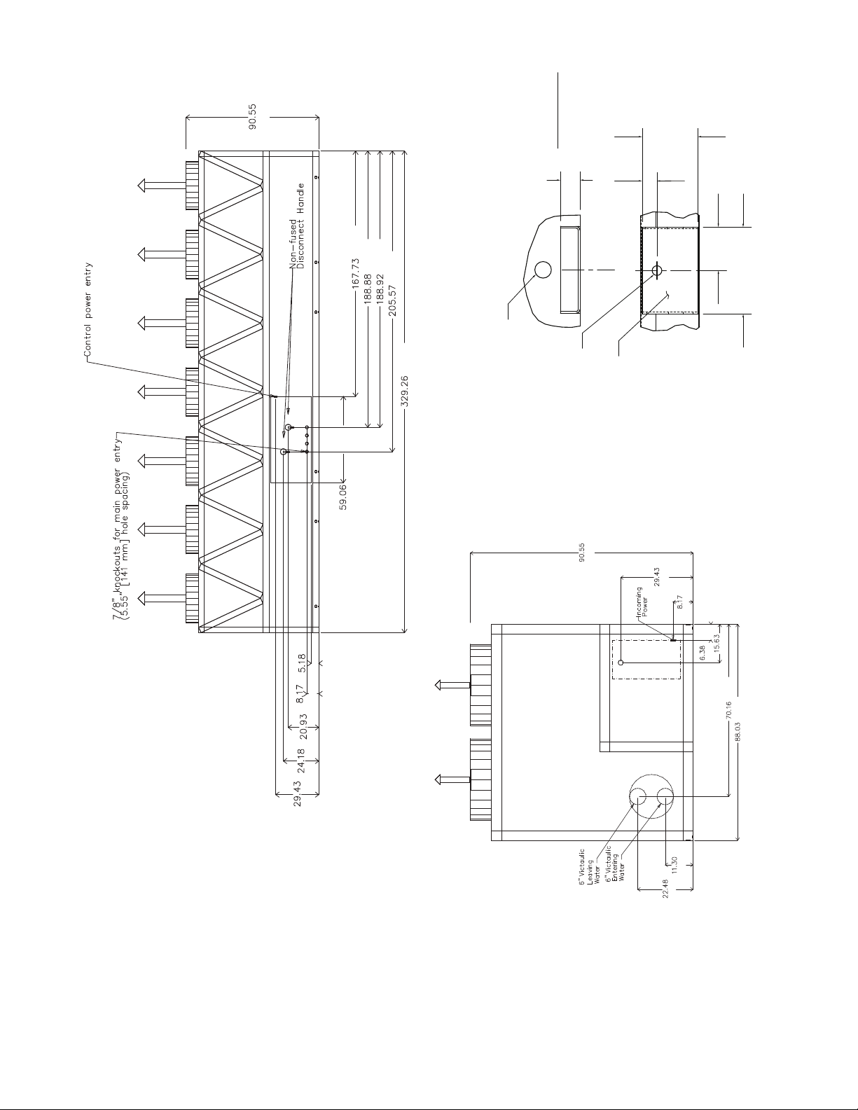
Fig. 7 — 30XA180,200 Air-Cooled Liquid Chiller Dimensions (cont)
MOUNTING PLATE
CONTACT SURFACE
TYPICAL 4 PLACES
5.0
[127]
1.75
1.50 DIA. [38.1]
RIGGING HOLE
[44]
[33]
1.31
MOUNTING
0.875 DIA.[22.2]
MOUNTING HOLE
[2300]
3.93
[100]
7.88
[200]
PLATE
[748]
[208]
[287]
[571]
[162]
[397]
[1782]
[2236]
15
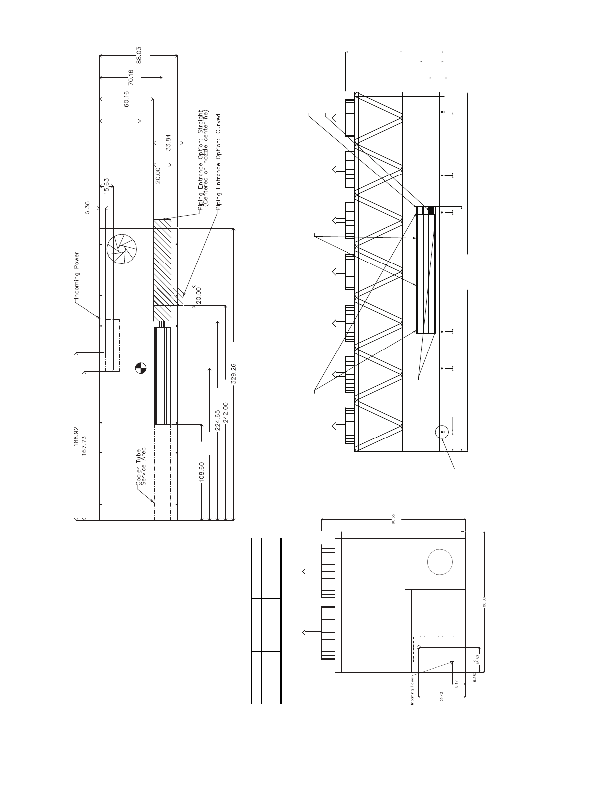
3/4 NPT Relief Conn. Female
6" Victaulic Entering Water
6" Victaulic Leaving Water
Cooler Vent
3/8 NPT
Cooler Drain
3/8 NPT
Rigging Holes
90.55
[2300]
22.48
[571]
11.3
[287]
329.26 [8363]
224.65 [5706]
109.03 [2769]58.08 [1475]
58.08 [1475]
33.97 [863]
33.96 [863]
18.07
[459]
[162]
[397]
A
[1528]
[1782]
[2236]
[508]
[860]
[508]
[4799]
[4260]
[8363]
[6147]
[5706]
B
[2758]
NOTES:
1. Unit must have clearances as follows:
Top — Do not restrict
Sides and Ends — 6 ft (1.8 m) from solid
surface.
2. Temperature relief devices are located on liq-
uid line and economizer assemblies and have
1
/
4
-in. flare connection.
3.
3
/
8
-in. NPT vents and drains located in each
cooler head at each end of cooler.
4. Drawing depicts unit with single point power,
standard two-pass cooler and nominal voltage
range of 380 to 575 v. Refer to the Packaged
Chiller Builder program for other configura-
tions.
5. Dimensions are shown in inches. Dimensions
in [ ] are in millimeters.
6. Allow 8 ft (2.4 m) on either side of unit for con-
denser coil removal.
30XA UNIT A B
220 46.17 [1173] 171.42 [4354]
240 46.23 [1174] 170.83 [4339]
a30-4409
TOP VIEW
LEFT END VIEW
FRONT VIEW
Fig. 8 — 30XA220,240 Air-Cooled Liquid Chiller Dimensions
[2300]
[208]
[748]
[2236]
[397]
[162]
16
[1500]
[748]
[614] [532]
[208] [132]
[2300]
[4260]
[4798]
[4799]
[5221]
[8363]
a30-4176
DETAIL "A"
BACK VIEW
RIGHT END VIEW
[2300]
[748]
[208]
[162]
[397]
[1782]
[2236]
[287]
[571]
Fig. 8 — 30XA220,240 Air-Cooled Liquid Chiller Dimensions (cont)
MOUNTING PLATE
CONTACT SURFACE
TYPICAL 4 PLACES
5.0
[127]
[44]
1.75
1.50 DIA. [38.1]
RIGGING HOLE
[33]
1.31
MOUNTING
0.875 DIA.[22.2]
MOUNTING HOLE
3.93
[100]
7.88
[200]
PLATE
17
90.55
[162]
[317]
A
[1805]
[2236]
[508]
[9555]
[7740]
B
[4784]
[5011]
[5747]
NOTES:
1. Unit must have clearances as follows:
Top — Do not restrict
Sides and Ends — 6 ft (1.8 m) from
solid surface.
2. Temperature relief devices are located
on liquid line and economizer assem-
blies and have
1
/
4
-in. flare connection.
3.
3
/
8
-in. NPT vents and drains located in
each cooler head at each end of
cooler.
4. Drawing depicts unit with single point
power and standard two-pass cooler.
Refer to the Packaged Chiller Builder
program for other configurations.
5. Dimensions are shown in inches.
Dimensions in [ ] are in millimeters.
6. Allow 8 ft (2.4 m) on either side of unit
for condenser coil removal.
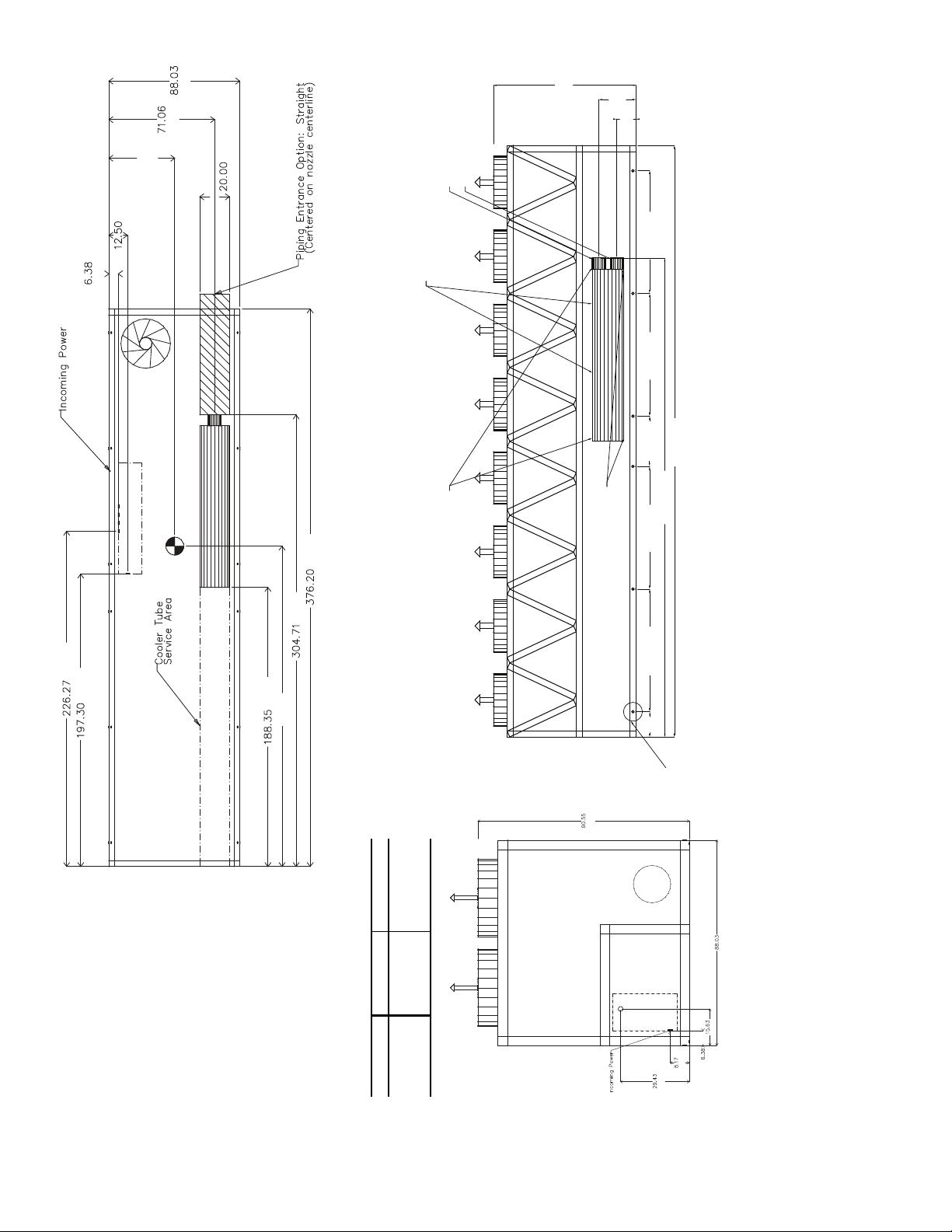
30XA UNIT A B
260 44.22 [1123] 216.16 [5490]
280 44.30 [1125] 215.86 [5483]
300 44.32 [1126] 216.18 [5491]
a30-4177
TOP VIEW
LEFT END VIEW
FRONT VIEW
[2300]
[2236]
[748]
[208]
[162]
[397]
Fig. 9 — 30XA260-300 Air-Cooled Liquid Chiller Dimensions
[2300]
8" Victaulic Entering Water
8" Victaulic Leaving WaterCooler Vent
3/4 NPT Relief Conn. Female
[310]
12.21
[600]
23.63
78.02 [1982]78.02 [1982]
78.02 [1982]
31.96 [812]
376.2 [9555]
3/8 NPT
Cooler Drain
3/8 NPT
304.71 [7740]
78.02 [1982]
16.1
[409]
Mounting Holes
Rigging Holes
(See Detail A)
18
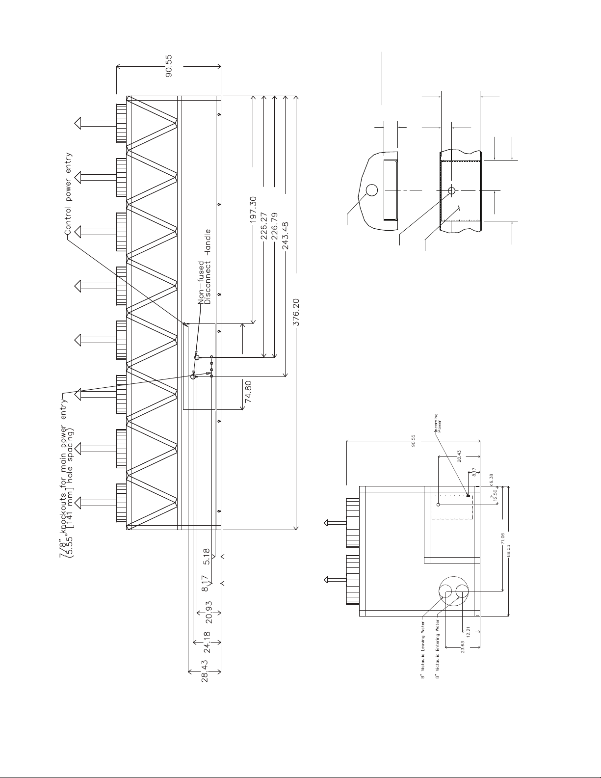
[722]
[614]
[532]
[208] [132]
[1900]
[9555]
[6184]
[5760]
[5747]
[5011]
[2300]
[2300]
[722]
[208]
[317]
[162]
[1805]
[2236]
[600]
[310]
a30-4178
3.93
7.88
[200]
DETAIL "A"
MOUNTING PLATE
CONTACT SURFACE
TYPICAL 4 PLACES
[100]
MOUNTING HOLE
0.875 DIA.[22.2]
MOUNTING
PLATE
1.50 DIA. [38.1]
RIGGING HOLE
[127]
5.0
[33]
1.31
1.75
[44]
BACK VIEW
RIGHT END VIEW
Fig. 9 — 30XA260-300 Air-Cooled Liquid Chiller Dimensions (cont)
19
3/4 NPT Relief Conn. Female
8" Victaulic Entering Water
8" Victaulic Leaving Water
Cooler Vent
3/8 NPT
Cooler Drain
3/8 NPT
Mounting Holes
Rigging Holes
(See Detail A)
90.55
[2300]
23.63
[600]
12.21
[310]
423.24
[10750]
349.02
[8865]
109.03
[2769]
78.02
[1982]
78.02
[1982]
58.08 [1475]
33.97
[863]
33.96
[863]
16.1
[409]
FRONT VIEW
[162]
[317]
A
[1805]
[2236]
[508]
[10750]
[8865]
B
[5910]
[6205]
[6941]
NOTES:
1. Unit must have clearances as follows:
Top — Do not restrict
Sides and Ends — 6 ft (1.8 m) from solid
surface.
2. Temperature relief devices are located on
liquid line and economizer assemblies and
have
1
/
4
-in. flare connection.
3.
3
/
8
-in. NPT vents and drains located in each
cooler head at each end of cooler.
4. Drawing depicts unit with single point power
and standard two-pass cooler. Refer to the
Packaged Chiller Builder program for other
configurations.
5. Dimensions are shown in inches. Dimen-
sions in [ ] are in millimeters.
6. Allow 8 ft (2.4 m) on either side of unit for
condenser coil removal.
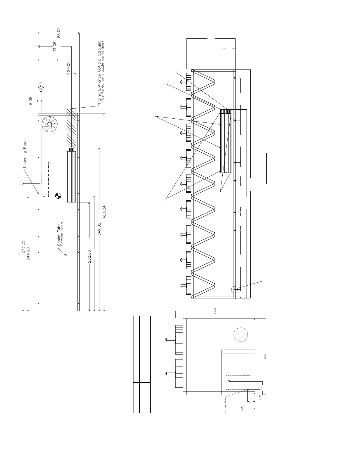
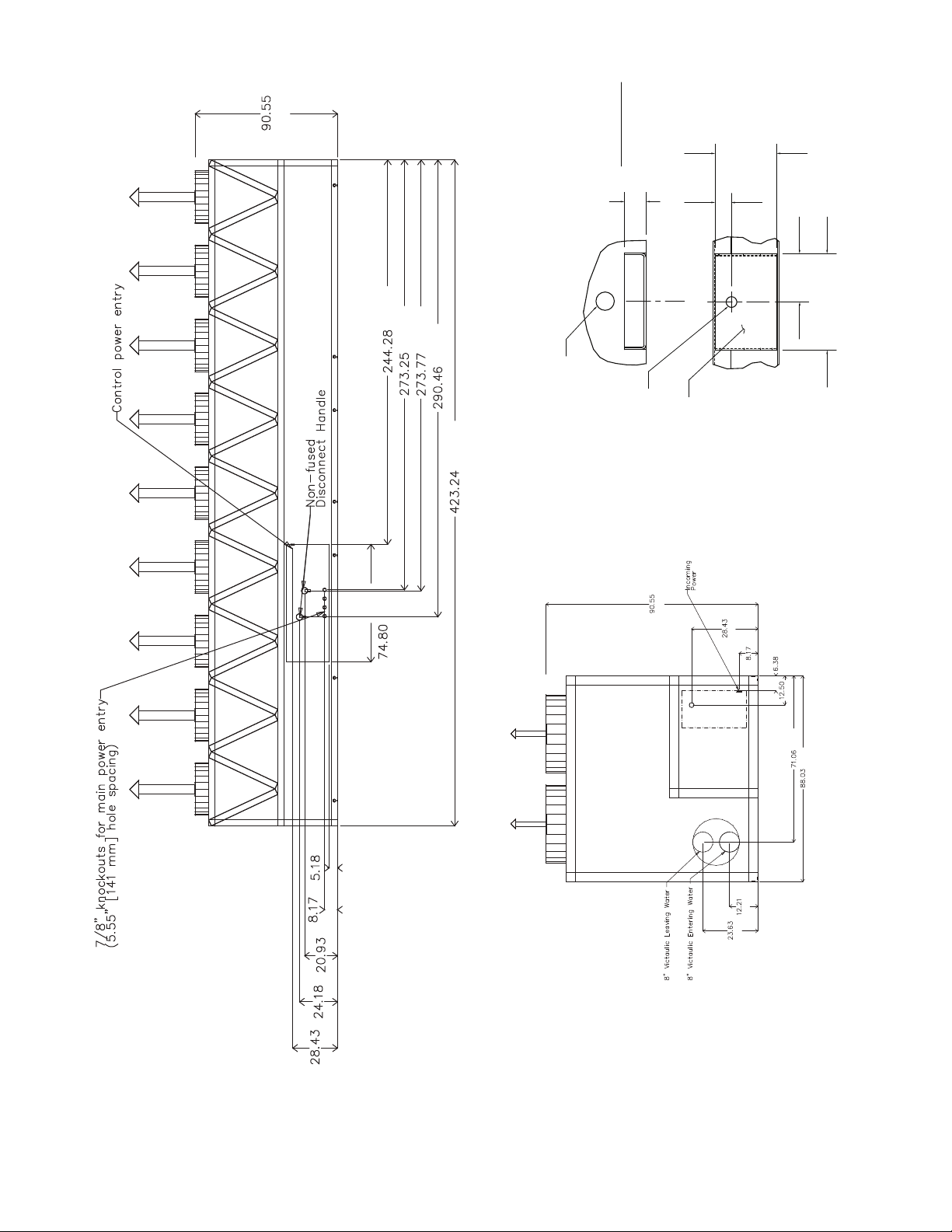
30XA UNIT A B
325 42.92 [1090] 246.16 [6252]
350 42.92 [1090] 246.72 [6267]
TOP VIEW
FRONT VIEW
LEFT END VIEW
[2300]
[2236]
[748]
[208]
[162]
[397]
Fig. 10 — 30XA325,350 Air-Cooled Liquid Chiller Dimensions
20
[2300]
[6205]
[6941]
[6954]
[7378]
[10750]
[1900]
[722]
[614]
[532]
[208] [132]
a30-4180
DETAIL "A"
BACK VIEW
RIGHT END VIEW
Fig. 10 — 30XA325,350 Air-Cooled Liquid Chiller Dimensions (cont)
MOUNTING PLATE
CONTACT SURFACE
TYPICAL 4 PLACES
5.0
[127]
[44]
1.75
1.50 DIA. [38.1]
RIGGING HOLE
[33]
1.31
MOUNTING
0.875 DIA.[22.2]
MOUNTING HOLE
[2300]
3.93
[100]
7.88
[200]
PLATE
[722]
[208]
[317]
[162]
21
[310]
[600]
[1805]
[2236]
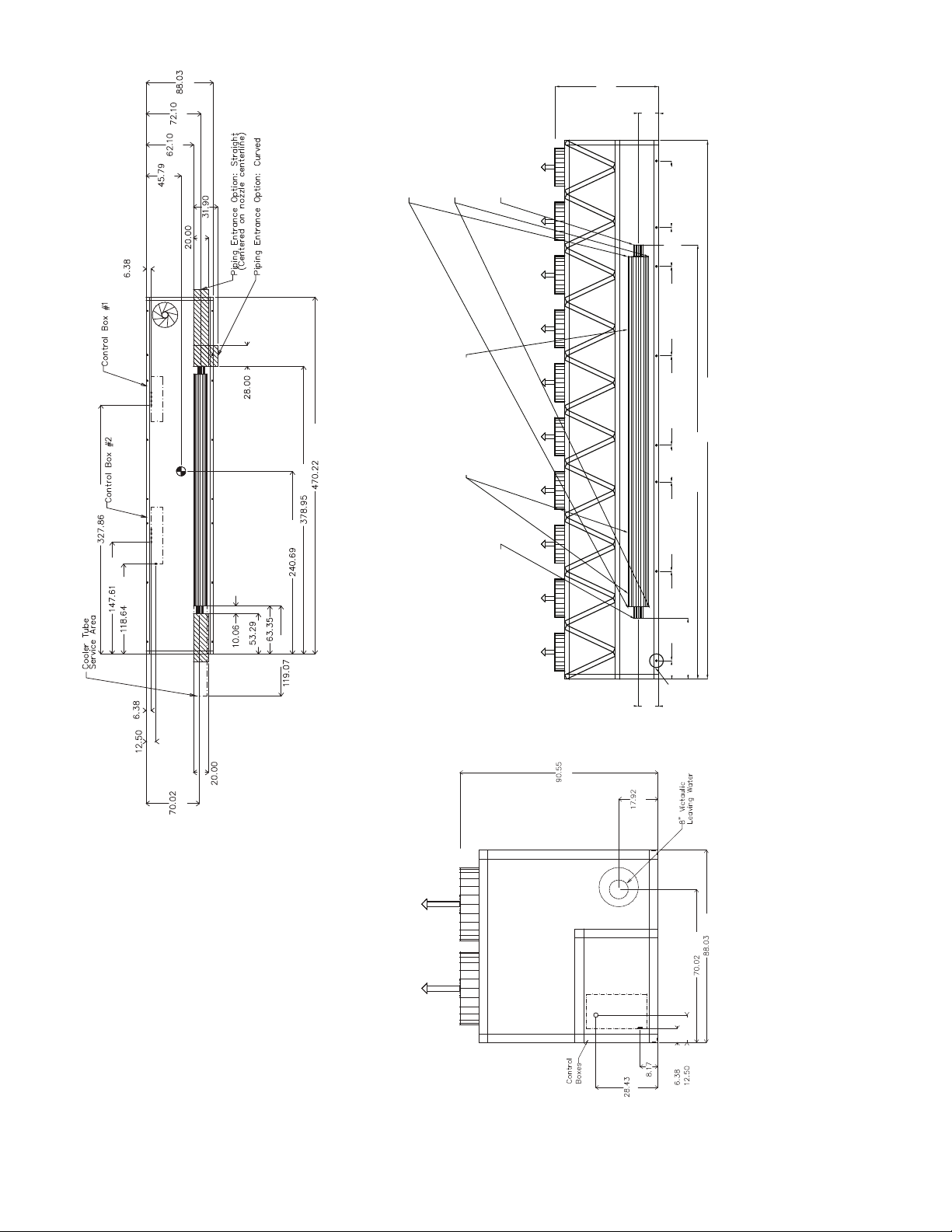
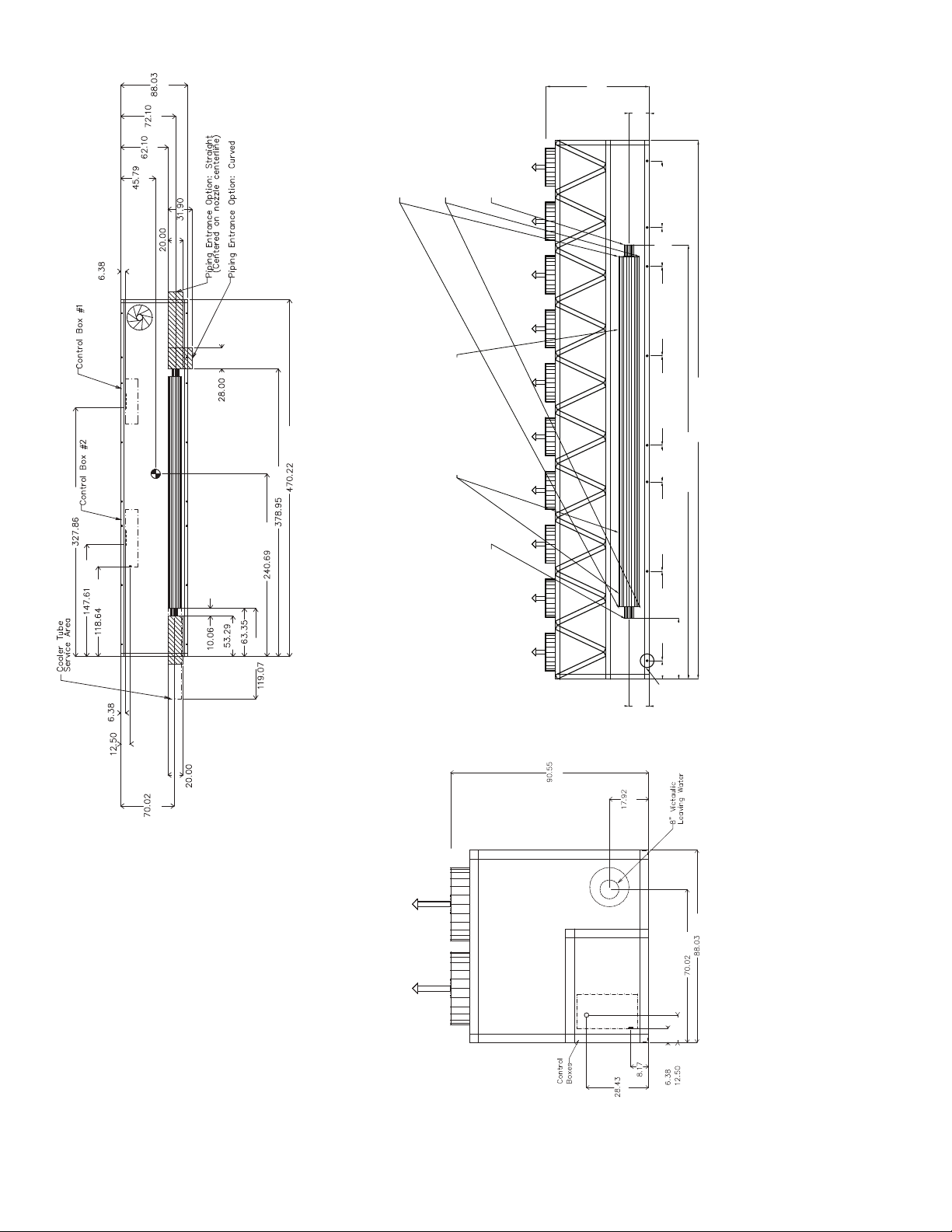
3/4 NPT Relief Conn. Female
8" Victaulic Entering Water8" Victaulic Leaving Water
Cooler Vent 3/8 NPT
located in cooler heads
Cooler Drain 3/8 NPT
located in cooler heads
Rigging Holes
(See Detail A)
90.55
[2300]
17.92
[455]
17.92
[455]
470.22 [11944]
378.95 [9625]
53.29 [1354]
78.02 [1982]78.02 [1982] 78.02 [1982]78.02 [1982] 58.08 [1475]
33.93
[862]
31.96
[812]
16.1
[409]
[162]
[508]
[810]
[1163]
[1577]
[1831]
[2236]
[711]
[11944]
[9625]
[6114]
[3024]
[508]
[317]
[162]
[256]
[1354]
[1609]
[3013]
[3749]
[8328]
NOTES:
1. Unit must have clearances as follows:
Top — Do not restrict
Sides and Ends — 6 ft (1.8 m) from solid
surface.
2. Temperature relief devices are located on liq-
uid line and economizer assemblies and have
1
/
4
-in. flare connection.
3.
3
/
8
-in. NPT vents and drains located in each
cooler head at each end of cooler.
4. Drawing depicts unit with single point power
and standard one-pass cooler. Refer to the
Packaged Chiller Builder program for other
configurations.
5. Actual cooler consists of two separate coolers
piped in series at the factory. Piping may be
split for rigging.
6. Dimensions are shown in inches. Dimensions
in [ ] are in millimeters.
7. Allow 8 ft (2.4 m) on either side of unit for con-
denser coil removal.
a30-4181
TOP VIEW
LEFT END VIEW
FRONT VIEW
Fig. 11 — 30XA400 Air-Cooled Liquid Chiller with Single Point Connections Dimensions
[2300]
[455]
[2236]
[1779]
[208]
[162]
[317]
22
[722]
[2300]
[722]
[208]
[162]
[317]
[1831]
[2236]
[455]
[2300]
[132]
[208] [532]
[614] [722]
[3013]
[3749]
[3763]
[4186]
[1900]
[7789]
[8328]
[8653]
[11944]
[1500]
[424]
[208] [132]
a30-4182
BACK VIEW
RIGHT END VIEW
3.93
7.88
[200]
DETAIL "A"
MOUNTING PLATE
CONTACT SURFACE
TYPICAL 4 PLACES
[100]
0.875 DIA.[22.2]
MOUNTING
PLATE
1.50 DIA. [38.1]
RIGGING HOLE
[127]
5.0
[33]
1.31
1.75
[44]
Fig. 11 — 30XA400 Air-Cooled Liquid Chiller with Single Point Connections Dimensions (cont)
23
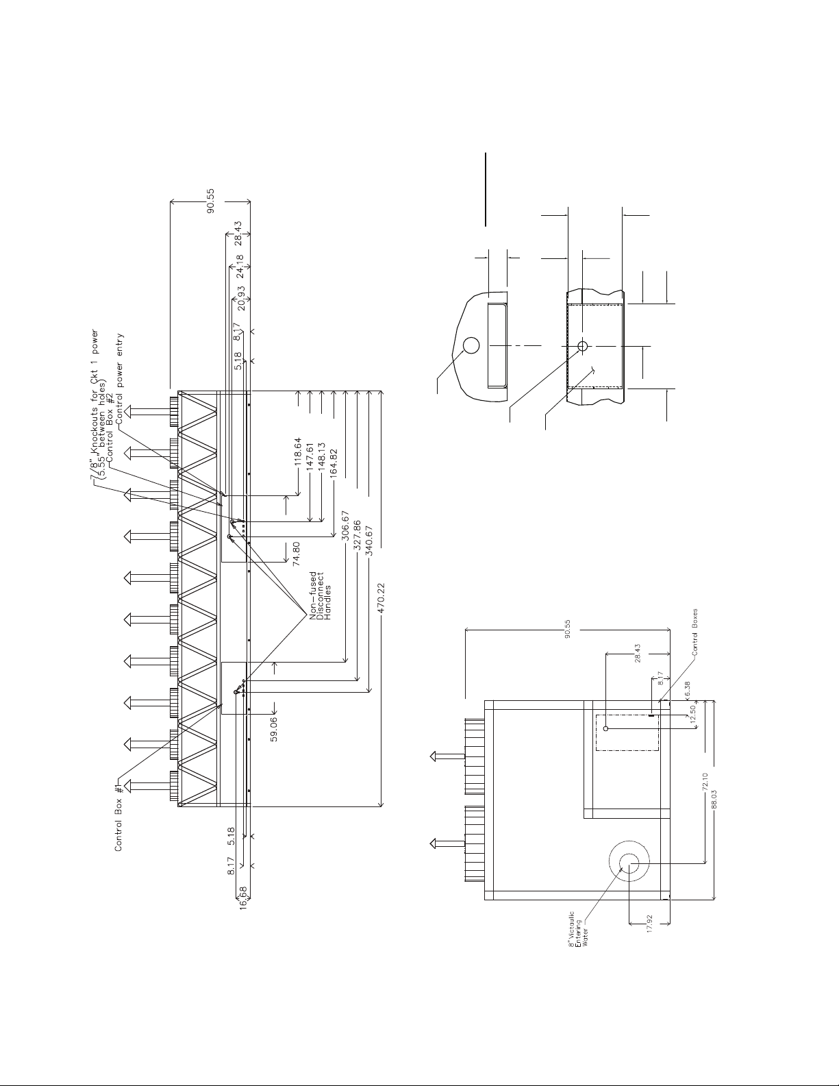
NOTES:
1. Unit must have clearances as follows:
Top — Do not restrict
Sides and Ends — 6 ft (1.8 m) from solid
surface.
2. Temperature relief devices are located on liq-
uid line and economizer assemblies and have
1
/
4
-in. flare connection.
3.
3
/
8
-in. NPT vents and drains located in each
cooler head at each end of cooler.
4. Drawing depicts unit with dual-point power
and standard one-pass cooler. Refer to the
Packaged Chiller Builder program for other
configurations.
5. Actual cooler consists of two separate coolers
piped in series at the factory. Piping may be
split for rigging.
6. Dimensions are shown in inches. Dimensions
in [ ] are in millimeters.
7. Allow 8 ft (2.4 m) on either side of unit for con-
denser coil removal.
a30-4181
TOP VIEW
LEFT END VIEW
FRONT VIEW
3/4 NPT Relief Conn. Female
8" Victaulic Entering Water8" Victaulic Leaving Water
Cooler Vent 3/8 NPT
located in cooler heads
Cooler Drain 3/8 NPT
located in cooler heads
Rigging Holes
(See Detail A)
90.55
[2300]
17.92
[455]
17.92
[455]
470.22 [11944]
378.95 [9625]
53.29 [1354]
78.02 [1982]78.02 [1982] 78.02 [1982]78.02 [1982] 58.08 [1475]
33.93
[862]
31.96
[812]
16.1
[409]
[8328]
Fig. 12 — 30XA400 Air-Cooled Liquid Chiller with Dual Point Connections Dimensions
[162]
[1577]
[1163]
[2236]
[1831]
[810]
[508]
[711]
[11944]
[9625]
[3749]
[3013]
[162]
[317]
[1779]
[508]
[6114]
[256]
[1609]
[1354]
[3024]
[2300]
[455]
[2236]
[1779]
[208]
[317]
[162]
[722]
24
 Loading...