


J/E/C
ご使用の前に必ずこの取扱説明書をお読みください。
なお、取扱説明書は必要に応じてご覧になれるよう大切に保管してください。
Read this operation manual before using the product.
Keep the manual in place for future reference.
在使用本产品之前 , 请务必先仔细阅读本使用说明书。
请务必妥善保管好本书 , 以便日后能随时查阅。( 保留备用 )
请在充分理解内容的基础上 , 正确使用。
取 扱 説 明 書
OPERATION MANUAL
使 用 说 明 书
BCTV Zoom Lens
广播电视变焦镜头
XJ100x9.3B AF
XJ100x9.3B
XJ95x8.6B
XJ86x13.5B
XJ86x9.3B AF
XJ86x9.3B
XJ80x8.8B
XJ76x9B
XJ75x9.3B
XJ72x9.3B
XJ60x9B
XJ27x6.5B AF
XJ27x6.5B
XJ23x7B


ENGLISH
VERSION
The English version is the operation manual
for counties other than Japan.

FCC REGULATIONS
This device complies with Part 15B of the FCC Rules. Operation is subject to the following two conditions: (1) This device
may not cause harmful interference, and (2) this device must accept any interference received, including interference
that may cause undesired operation.
Note: This equipment has been tested and found to comply with the limits for a Class A digital device, pursuant to Part
15B of the FCC Rules.
These limits are designed to provide reasonable protection against harmful interference when the equipment is operated
in a commercial environment. This equipment generates, uses, and can radiate radio frequency energy and, if not
installed and used in accordance with the instruction manual, may cause harmful interference to radio communications.
Operation of this equipment in a residential area is likely to cause harmful interference in which case the user will be
required to correct the interference at his own expense.
Do not make any changes or modications to the equipment unless otherwise specied in the manual. If such changes
or modications should be made, you could be required to stop operation of the equipment.
Canadian Radio Interference Regulations
CAN ICES-3(A)/NMB-3(A)
We, Canon Inc., in Japan and CANON EUROPE LTD., in U.K., conrm that the BCTV zoom lens is conformity with the
essential requirements of EC Directive(s) by applying the following standards:
EN55103-1 and EN55103-2
Note:
a) Applicable Electromagnetic Environments:
E1 (residential), E2 (commercial and light industrial), E3 (urban outdoors) and E4 (controlled EMC environment,
ex. TV studio).
b) Use of shielded cable is required to comply with limits specied by above standards.
NOTE: Above declaration is applicable to 12V DC input zoom lenses.
Dieses Produkt ist zum Gebrauch im Wohnbereich, Geschäfts- und Gewerbebereich sowie in Kleinbetrieben
vorgesehen.

European Union (and EEA) only.
This symbol indicates that this product is not to be disposed of with your household waste, according
to the WEEE Directive (2002/96/EC) and your national law. This product should be handed over
to a designated collection point, e.g., on an authorized one-for-one basis when you buy a new
similar product or to an authorized collection site for recycling waste electrical and electronic
equipment (EEE). Improper handling of this type of waste could have a possible negative impact
on the environment and human health due to potentially hazardous substances that are generally
associated with EEE. At the same time, your cooperation in the correct disposal of this product will
contribute to the effective usage of natural resources. For more information about where you can
drop off your waste equipment for recycling, please contact your local city ofce, waste authority,
approved WEEE scheme or your household waste disposal service.
Your cooperation in the correct disposal of this product will contribute to the effective usage of natural resources and will
avoid incurring administrative sanctions according to art. 50 and following of Italian legislative decree 22/97.
For more information regarding return and recycling of WEEE products, please visit
www.canon-europe.com/environment.
(EEA: Norway, Iceland and Liechtenstein)

PREFACE
Thank you for purchasing the Canon BCTV zoom lens. This operation manual explains the functions and operating instructions
for the Canon BCTV zoom lens. It also describes precautions for handling the lens. Read this operation manual carefully
before using the product. Also, keep this manual in a safe place where it can easily be referenced whenever necessary.
This operation manual is applicable for the following models:
Model name Operation system Interface
XJ100x9.3B AF
XJ100x9.3B
XJ95x8.6B
XJ86x13.5B
XJ86x9.3B AF
XJ86x9.3B
XJ80x8.8B
XJ76x9B
XJ75x9.3B
XJ72x9.3B
XJ60x9B
XJ27x6.5B AF
XJ27x6.5B
XJ23x7B
IESD
BA
BB
CA
CB
CC
HA
HB
HH
IA
IB
IH
PH
SA
SB
SC
SH
XJ60x9B
XJ27x6.5B
XJ23x7B
IESDA
PRODUCT CONFIGURATION
Make sure that the following items are included in a package.
(If you nd any item missing, please contact the dealer from whom you purchased this product.)
Lens Body
Oparation Manual
(this booklet)
CD-ROM
(technical documents)
*1
Dust Cap
(attached to the lens)
Connector Cap
(attached to the lens)
*2
Hood Cap (attached to the lens)
IS Operation Unit
*3
*1 Depending on the model, the technical documents may also be in the form of a booklet.
*2 The connector cap is provided to protect the interface connector(s) between the lens and the camera. For some lens models, two (2) pieces
are provided.
*3 The IS operation unit comes only with models with the IS function. However, it is available as an option with the XJ95x.
• Accessories other than those mentioned above may be required depending on the specications of your unit. For more
details, contact our sales representative.
• The illustrations shown on this page and subsequence pages are those of the XJ95x8.6B. Shapes of lens may be slightly
different between models.
• The illustrations of accessories shown in this booklet are those of standard specications. Shapes may be slightly different
between specications.
GENERAL SAFETY
INFORMATION
Be sure to observe the safety warnings and cautions
provided on the product and in this operation manual.
Failure to observe these warnings and cautions may result
in injury or accident.
Read this operation manual carefully to familiarize yourself
with its contents and ensure that you can operate the
product properly.
Also, store this manual in a safe place where it can easily be
referenced whenever necessary.
This operation manual uses the following symbols and terms
to identify hazards in order to prevent accidents.
WARNING
T hi s i nd ic a tes a p ote n tia l ly
hazardous situation which, if not
heeded, may res ult in dea th or
serious injury to you or others. Be
sure to heed all warning notices to
ensure safe operation at all times.
CAUTION
Indicate s potentially hazardous
situations which, if not heeded, may
result in minor or moderate injury to
you or other persons, or property
damage.
* (NOTE)
Emphasizes essential information
which, if not heeded, may make the
product unworkable or cause it to
function improperly.
Helpful information for operation is
also provided.
HANDLING THE PRODUCT
WARNING
1. Never allow water or other liquids to enter or be spilled on
the product. Immediately stop using the product if water
or other liquids get inside the product. Otherwise, re or
electric shock could result.
2. Do not stare at the sun or any other source of highintensity light through the lens. Doing so could injure your
eyes.
CAUTION
1. Always grasp the specied portions of the lens when
transporting the lens, or when attaching or detaching it to
or from the camera head.
Otherwise, the lens may fall, possibly causing injury.
2. All mountings must be tightened securely. If any of the
mountings become loose, the lens may fall, possibly
causing injury.
3. Always grasp the connector itself when connecting
or disconnecting the demand cable. Pulling on the
cable portion may result in damage to the cable, such
as breakage of the conductors. Power leaking from a
damaged cable may present a re or electric shock
hazard.
4. Check periodically (for instance, every 6 months to 1
year) that all mountings are securely tightened. If any of
the mountings become loose, the lens may fall, possibly
causing injury.
5. If it becomes necessary to repair this product, or to
perform any operations or adjustments not mentioned in
this operation manual, contact Canon’s representative or
the dealer who originally supplied the lens.
6. When this product is used in direct sunlight, the inside
of the unit may be heated to high temperatures. When
it is expected that the unit is exposed to elevated
temperatures, take measures against heat as appropriate
on the customer’s side.
* (NOTE)
1. Protect the lens from strong impacts of shocks. Striking
or dropping the lens could damage it.
2. Since the lens is not completely waterproof, avoid directly
exposing the lens to rain or snow. When the lens has to
be used in rain or snow, provisions should be made to
prevent the lens from getting wet.
3. Under dusty conditions, the lens should be mounted or
dismounted with a cover placed over the mount so as to
prevent dust from entering the inside.
4. Do not bring the lens from an area with a very cold
ambient temperature abruptly into a warm room, as the
lens may fog on the inside. If this happens, the lens
cannot be used until the condensation clears. Take
adequate countermeasures to ensure that condensation
does not form.
5. If the lens is to be used in adverse environments, such
as in a chemical laden atmosphere, consult with Canon’s
representative beforehand.
DEALING WITH
ABNORMALITIES
WARNING
1. Should any of the abnormalities described below occur,
contact Canon’s representative or the dealer who
originally supplied the lens.
• Smoke, unusual smell or unusual noise
• Entry of foreign objects (including metals or liquids)
inside the lens.
MAINTENANCE AND
INSPECTION
WARNING
1. Unplug the demand cable and remove the lens from the
camera, before attempting to clean the lens. Never use
ammable substances such as benzene or thinner for
cleaning, as this may present a serious re or electric
shock hazard.

* (NOTE)
1. Dust or ngerprints on the lens surface
Gently blow or brush away dust or dirt on the lens surface
using a lens blower or a soft lens brush.
Remove any ngerprints or other stains with a soft clean
cotton cloth moistened with lens cleaning uid or lens
cleaning paper (Shilbon paper, etc.).
Gently swirl the cloth or paper over the lens surface. Start
rst at the center area of the lens and rub with a circular
motion, then gradually shift the circle until whole lens
surface has been covered.
Be careful not to rub dust across the lens, as the lens
surface may be scratched.
2. Periodic inspection
A periodic inspection (about once a year) is
recommended.
The inspection and maintenance interval depends on
the operating conditions, the frequency of use, and the
environment. If required, overhaul the lens.
STORAGE
CAUTION
1. Always attach the hood cap and the dust cap before
storing the lens.
Storing the lens without these caps attached may present
a re hazard due to light convergence effect.
* (NOTE)
1. If moisture enters the lens due to mist or light rain, etc.,
immediately wipe away any water with a dry cloth and
then seal the lens in a vinyl bag together with a desiccant
(as fresh as possible) to completely remove the moisture
from inside the lens.
TO THE CUSTOMER
1. Canon shall bear no responsibility for damage resulting
from improper operation of this product by the customer.
2. Canon shall make no guarantees about the product
quality, functions, or operation manual and its
marketability and suitability for the customer’s purpose.
Moreover, Canon shall bear no responsibility for any
damage, direct or incidental, that results from usage for
the customer’s purpose.
3. Canon shall make no guarantees about the results
obtained using this product.
4. The product specications, conguration, and
appearance are subject to change without prior notice.
5. For further information on repairs, maintenance, or
adjustments not mentioned in this operation manual,
contact your Canon dealer or your Canon sales
representative.
6. Note that Canon may be unable to undertake servicing
or repair of a product if it is modied without consulting
Canon or your Canon sales representative.
CANON INC.
30-2, Shimomaruko 3-chome, Ohta-ku, Tokyo
146-8501, Japan
Canon Europe Ltd
3 The Square, Stockley Park, Uxbridge, Middlesex,
UB11 1ET UK
All rights reserved. No part of this operation manual may
be reproduced or copied in any from or by any means
without the written permission of Canon Inc.

E1
1 HOWTOMOUNT E2
1-1 MountingtheLensontotheCamera.........................................................................E2
1-2 MountingtheAccessoriesforFullServoOperation..................................................E3
1-3 MountingtheAccessoriesforSemi-servoOperation................................................E5
1-4 MountingtheAccessoriesforManualControlSystem..............................................E6
2 PREPARATION E7
2-1 InitializeOperation(OnlyModelswithaDisplay)......................................................E7
2-2 BackFocusAdjustment.............................................................................................E7
2-3 RemovingandInstallingtheLensShroud.................................................................E8
2-4 IrisGainAdjustment..................................................................................................E8
2-5 IrisModeSetting(Option).......................................................................................E10
2-6 SettingontheInformationDisplay..........................................................................E11
2-7 IncorporableFocusServoDemand(Option)...........................................................E12
3 OPERATION E13
3-1 ZoomandFocusOperation.....................................................................................E13
3-2 IrisOperation...........................................................................................................E14
3-3 ExtenderOperation.................................................................................................E15
3-4 OperatingtheAF(AutoFocus)Function(OnlyModelswithAFFunction).............E15
3-5 OperatingtheISFunction(OnlyModelswithISFunction).....................................E15
4 OtherFunctionsandOptions E18
4-1 CheckingforLowPower.........................................................................................E18
4-2 UsinganExternalPowerSource............................................................................E18
4-3 HeaterSystem(Option)...........................................................................................E18
4-4 WiperSystem(Option)............................................................................................E18
4-5 NitrogenGasFilling(Option)...................................................................................E19
4-6 ZoomControlSelectingSwitch(OnlyXJ27xAFandXJ27x)..................................E19
5 SPECIFICATIONS E20
APPENDIXES DISPLAYOPERATIONMANUAL
INDEX END

E2
E3
1 HOWTOMOUNT
1-1 Mounting the Lens onto
the Camera
Mounting the Lens onto the Largesized Camera
1
Make sure that the panning and tilting mechanism
of the cam head on the tripod/pedestal is securely
locked.
2
Turn the mount lock knob of the camera 90 degrees
counterclockwise as viewed from the lens. Also,
remove the protection plate/cap from the camera.
3
Remove the connector cap(s) on the rear surface of
the lens and the dust cap.
4
Carefully holding the lens with both hands, mount it
by hanging the V-wedge of the lens over that of the
camera, with aligning the lens locating pin of the lens
with U-shaped groove of the V-wedge of the camera.
V-Wedge
Lens Locating
Pin
Mounting Pin
Mount Lock
Knob
Pin Hole
U-Shaped
Groove
V-Wedge
CAUTION
The lens is quite heavy. When lifting the lens, use both hands to
hold two recessed handles on both side of the lens shroud, and
assure the correct lifting posture.
Failure to do so may cause the lens to drop, resulting in damage to
the lens and/or injury.
5
After lining up the lens correctly, press the lens
toward the camera, and at same time make sure that
the mounting pin at the bottom of the lens mount is
tted securely into the corresponding pin hole on the
camera. Then, turn the mount lock knob of the camera
clockwise (to the direction indicated by the arrow/see
the gure below) to secure the lens to the camera.
V-Wedge
Lens Locating
Pin
Mounting Pin
Mount Lock
Knob
Pin Hole
U-Shaped
Groove
V-Wedge
* (NOTE)
• The connector(s) on the lens and the camera are connected
automatically by performing steps 4 and 5. If an attempt is made
to connect them forcibly without lining up the spring pin with the
pin hole as described in step 5, the lens and camera connectors
may be damaged.
• After installing all units, including the operation’s accessories, on
tripod or pedestal, adjusting work for balance of the cam head is
required.
Mounting the Lens onto the Portable
Camera
When using the portable camera, the supporter to mount the
lens is required.
Depending on the camera models, the supporters which
can be used with a camera differ. For details, contact your
Canon dealer or your Canon sales representative.
E3
1 HOW TO MOUNT
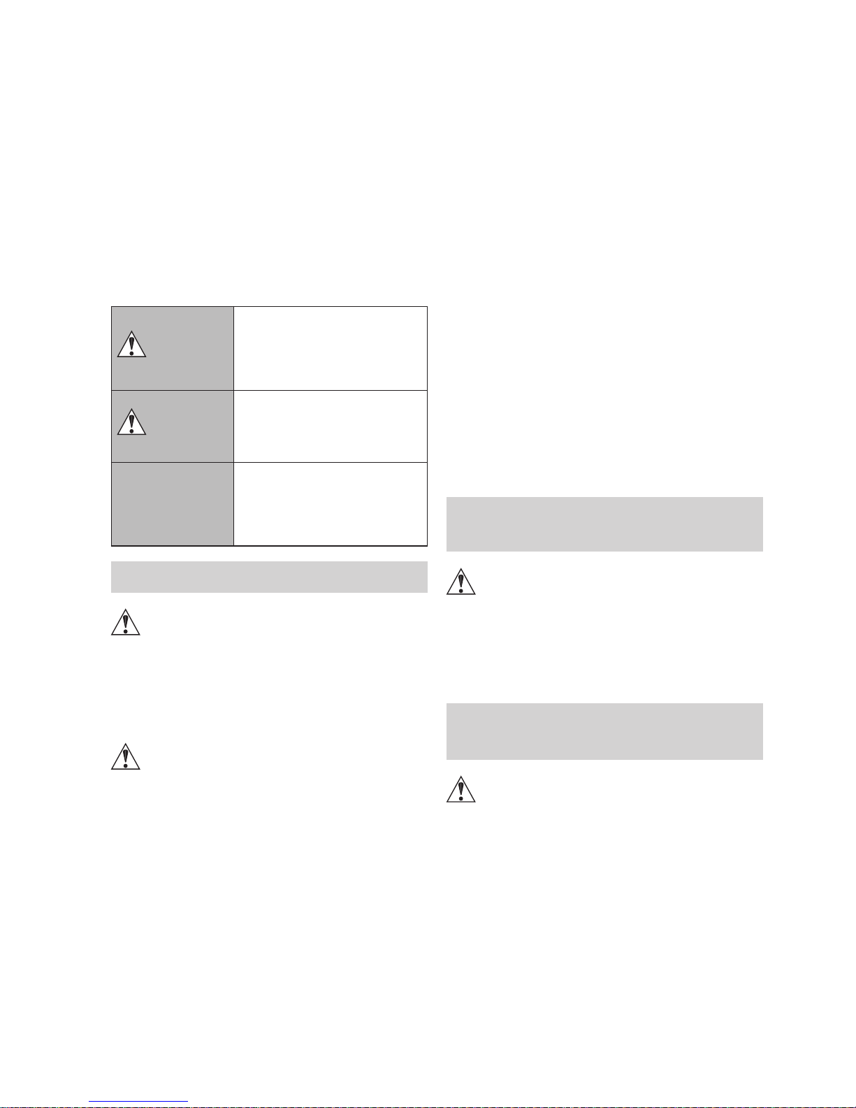
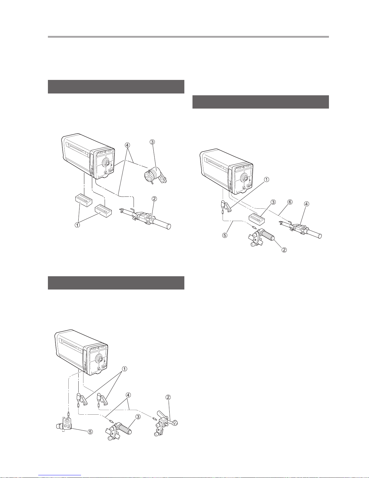
1-2 Mounting the
Accessories for Full
Servo Operation
The servo demand is mounted and connected as shown in
the gure below. When mounting the various demands, refer
to the operation manual for the respective demand.
① Servo module
② Zoom servo demand
③ Focus servo demand
④ Demand cable
Mounting the Servo Module onto the
Lens
It is necessary to mount the servo module to the zoom and
focus couplings located in the bottom compartment of the
lens.
* (NOTE)
The same servo module is used for both zoom and focus couplings.
So, it can be mounted on either the zoom or focus coupling.
1
Before mounting a module to the lens, turn the lock
screw of the module counterclockwise until the lock
axis comes out to its a half way of length.
2
Press the module in the direction of arrow “A”, so
that the key pins on the lens are inserted in the key
grooves of the module.
Coupling B
Index Line
(White Line)
Arrow A
Key
Groove
Bottom compartment of the lens
Lock Axis
Lock Screw
Servo Module
Coupling A
Key Pin
3
Mate the coupling A of the module with the coupling
B of the lens. And then, fully push the module in the
direction of arrow “B” until it stops.
4
Finally, turn the lock screw of the module clockwise to
secure it. By using a coin, tighten rmly the lock knob.
Arrow B
Lock Screw
Lock
Next, as the same procedure, install the servo module on
the other joint. It does not matter which is installed rst,
either the zoom or the focus.
* (NOTE)
When mating couplings A and B, push the servo module in
completely, so that the index line (white line) on the circumference
of coupling B is entirely hidden. If index line is not completely
hidden, the servo module may fail to operate, or it may generate
abnormal acoustic noise.
Mounting the Switch Box
1
Mount the switch box to the panhandle of the tripod,
using the attached clamp.
2
Connect the switch box to the lens, using the included
cable.
E4
1 HOW TO MOUNT
E5
Switch Box Cable
“SW. BOX” Connector
Lens
Switch Box
Pan Handle
Clamp
Clamp fixing knob
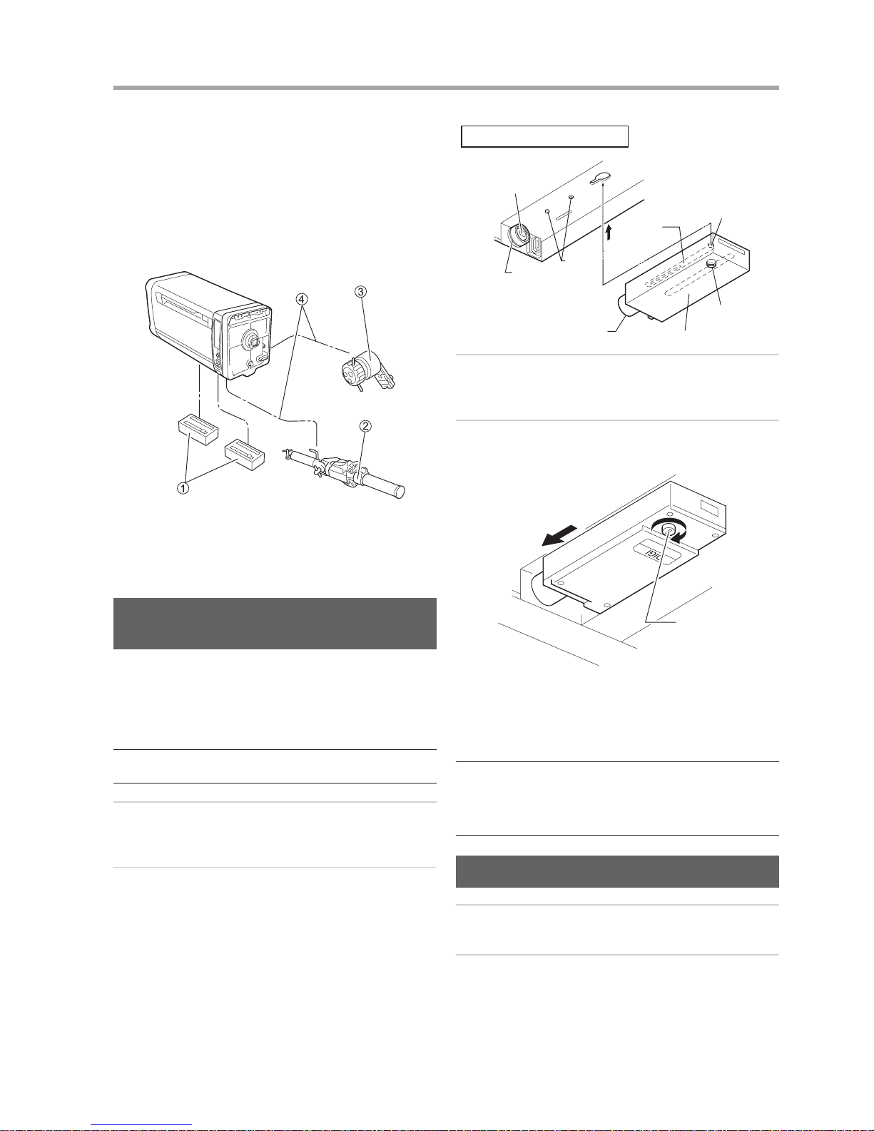
Mounting the AF (Auto Focus) Demand
(Only Models with AF Function)
The AF demand unit is mounted and connected as shown
in the gure below. Follow the procedure in the operation
manual for the demand to mount and connect the demand.
AF Demand
FDJ-P41
Demand Cable
Lens
Fixing
Ring
• This figure shows the
case with the AF demand
FDJ-P41 mounted on the
right side as viewed from
the camera.
Lock
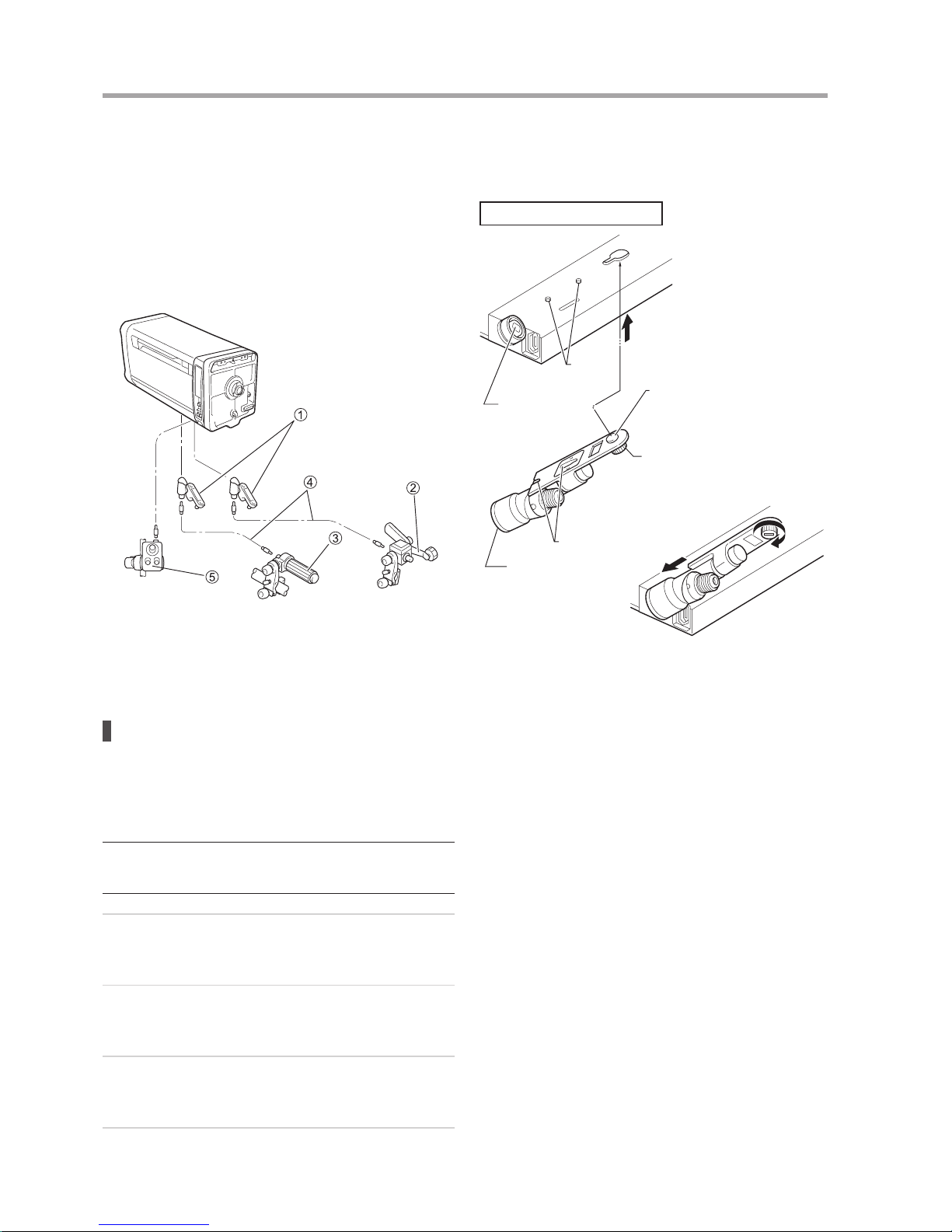
Mounting the Accessories for IS
Operation (Only Models with IS
Function)
Mounting the IS operation unit
1
Plug the connector of the IS operation unit into the
receptacle labeled “AUX” on the left side of the lens
(as viewed from the camera).
2
The IS Indicator unit on the other branch of the cable
comes with an anchoring screw. Mount it to the
location (such as on the edge of the viewnder) where
the ON/OFF status of the LEDs can be observed.
The IS indicator unit is not necessary for the camera
equipped with display function.
Lens
IS Operation Switch
Fixing Belts
IS Indicator Unit
(or Viewnder)
“IS Controller” Connector
Seeing the IS operating statuses in the
viewnder
When using a camera provided with a function for receiving
the signals indicating that the IS function is operating or
stopped from the lens side and displaying this operating
status on its viewnder, it is possible to connect only the IS
Operation Switch and operate it to perform these functions.
Remove the IS indicator unit that is connected partway
along the cable from the IS operation unit.
E5
1 HOW TO MOUNT
Connecting Wiper Switch Box
(Option)
When using separately purchased switch box for the
wiper equipped lens, connect it to the lens using the
dedicated cable. (Connection method varies by switch box
specications.)
Lens
“SW. BOX” Connector
Wiper Switch Box
Cable
Wiper Switch Box
(Shapes and connections
vary by specications.)
Connecting the “VIRTUAL” Cable
(Only Models with "VIRTUAL"
Connector)
The lens is equipped with the connector labeled “VIRTUAL”
on its left side (as viewed from the camera). This connector
can be used for connection with an interface to virtual
systems. Zoom, focus and iris signals can be output in three
types of communication data; analog signal, encoder pulse
train and RS-422.
* (NOTE)
Connector location may vary by models.
“VIRTUAL”
Connector
To Virtual System
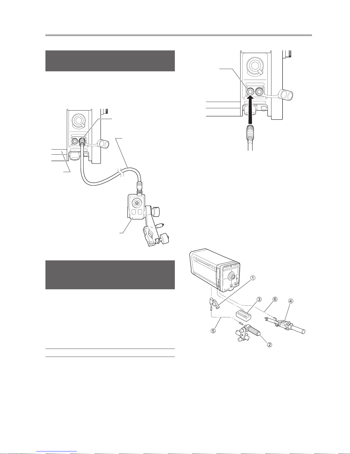
1-3 Mounting the
Accessories for Semiservo Operation
The zoom servo demand and the exible focus control unit
are mounted and connected as shown in the gure below.
When mounting the various demands, refer to the operation
manual for the respective demand.
① Flexible module
② Flexible focus control unit
③ Servo module
④ Zoom servo demand
⑤ Flexible cable
⑥ Demand cable
E6
1 HOW TO MOUNT
1-4 Mounting the
Accessories for Manual
Control System
Mount and connect the exible zoom and focus control units
as shown in the gure.
When mounting the various demands, refer to the operation
manual for the respective demand.
① Flexible module
② Flexible zoom control unit
③ Flexible focus control unit
④ Flexible cable
⑤ Switch box unit
Mounting the exible module
It is necessary to mount the exible module to the zoom and
focus couplings located in the bottom compartment of the
lens.
* (NOTE)
The same exible module is used for both zoom and focus
couplings. So, it can be mounted on either the zoom or focus
coupling.
1
Before mounting the module to the lens, turn the lock
screw of the module counterclockwise until the lock
axis comes out to its a half way of length.
2
Press the module in the direction of arrow “A”, so
that the key pins on the lens are inserted in the key
grooves of the module.
3
Mate the coupling A of the module with the coupling
B of the lens. And then, fully push the module in the
direction of arrow “B” until it stops.
4
Finally, turn the lock screw of the module clockwise to
secure it. By using a coin, tighten rmly the lock knob.
Next, as the same procedure, install the exible module
on the other joint. It does not matter which is installed rst,
either the zoom or the focus.
Bottom compartment of the lens
Key Pin
Arrow A
Lock Axis
Lock
Coupling B
Lock Screw
Key Groove
Coupling A
Arrow B

E7
2 PREPARATION
2-1 InitializeOperation
(OnlyModelswithaDisplay)
This lens has a built-in encoder for a position sensor of
zoom, iris and focus, and enables high-accuracy control and
advanced for virtual interface. The correct position must be
detected for these functions to operate correctly.
The Auto [ON]/Manual [OFF] setting of initialization can be
set from the information display.
Auto [ON]
The lens is automatically initialized on power-up.
(When in servo mode)
Manual [OFF]
After the power is turned on, position detection is
performed when the lens passes the specic position
(normally near the center) in the course of lens
operation.
* Default setting at factory: OFF
For the detailed setting method, refer to the “Display
OperationManual” at the end of this Operation Manual.
How to detect the position of ZOOM
Initialize
operation
Howtodetecttheposition
ON (Auto)
When the power is turned on, the lens automatically
detects the position. Then, it returns to the position
where it used to be when the power was turned on.
OFF (Manual)
Immediately after the power is turned on, the lens
operates at a temporary position, and the position is
corrected when the lens passes the specic position
and the position is detected.
How to detect the position of FOCUS
Initialize
operation
Demand Howtodetecttheposition
ON (Auto)
Connected
When the power is turned on, the lens
automatically detects the position. Then,
it returns to the position instructed by
command from the demand.
Not
connected
When the power is turned on, the lens
automatically detects the position. Then,
it returns to the position where it used to
be when the power was turned on.
OFF
(Manual)
Connected
When the power is turned on, the lens
automatically detects the position. Then,
it returns to the position instructed by
command from the demand.
Not
connected
The lens does not automatically
detect the position when the demand
is not connected. When the demand
is connected, the lens automatically
detects the position. Then, it returns to
the position instructed by command from
the demand.
Whenpositiondetectionisfailed:
• The position signal sent from the lens to the camera and
its indication on the information display will be incorrect.
Notes
• Iris is always initialized when powered on regardless of
auto mode or manual mode.
• During initialization, lens operation is disabled. After
initialization is completed, the lens returns to the position
where it used to be before initialization. However, if the
lens is operated in the position servo mode, the lens
moves to the currently controlled position.
• The initialization operation can be enabled/disabled on
the information display. When any initialization operation
is changed, turn off then on the power for the changes to
take effect.
The “Initialize Error!” message appears whentheservo
moduleisnotmountedcorrectly, the lens is forcibly
locked, or some other reason.
In such case, check the lens condition, clear the problem,
and then turn off and on the power again.
Initialize Error! message
Initialize
Error!
2-2 BackFocusAdjustment
If the relationship between the image plane of the zoom
lens and that of the television camera is incorrect, the object
goes out of focus when the lens is zoomed. Follow the steps
below to adjust the back focus of the lens.
1
Select an object at an appropriate distance (XJ27xAF/
XJ27x/XJ23x: 3 to 5 m, XJ100xAF/XJ100x/XJ95x/
XJ86xAF/XJ86x/XJ75x/XJ72x/XJ60x: 10 to 15 m
recommended). Use any object with sharp contrast to
facilitate the adjustment work.
2
Set the lens to 1x [status without using an extender].
3
Set the iris fully open.
4
Set the lens to the telephoto angle.
F.B. Adjusting Knob
F.B. Lock Knob

E8
2 PREPARATION
E9
5
Bring the object into focus by focus operation.
6
Set the lens to the widest angle.
7
Loosen the F.B. lock knob, and then turn the F.B.
adjusting knob to bring the object into focus.
8
Repeat steps 4 to 7 several times, until the object
is brought into focus at both the widest angle and
telephoto ends.
9
After making sure that the object is in sharp focus,
tighten the F.B. lock knob.
The adjustment procedure is now completed.
2-3 Removing and
Installing the Lens
Shroud
When any electrical setting or adjustment is required,
remove and install the lens shroud following the steps
below.
Fastener type
1
Release the fasteners on both sides of the lens
shroud, then pull the shroud forward to remove from
the lens body.
2
When installing the lens shroud back in place, align
the shroud to the guide rails of the lens body, and then
push the shroud until it stops at the end of the mount.
Press the shroud fasteners near to the end of the
mount side to lock the shroud.
Fastener
Recessed Handle
(Both side of the lens)
Lens Shroud
* (NOTE)
Make sure that the fasteners of the lens shroud are always locked
when it is mounted on the lens.
Knob type
1
Turn the shroud mounting knobs on the bottom of the
lens shroud counterclockwise.
2
Hold two recessed handles on both side of the lens
shroud, and then pull and remove the shroud from the
lens body.
Shroud
mounting knobs
Recessed Handle
(Both side of the lens)
Lens Shroud
3
When putting the lens shroud back on the lens body,
align the shroud to the guide rails of the lens body, and
then push the shroud until it is stopped at the end of
the mount.
Turn the shroud mounting knobs on the bottom
clockwise.
* (NOTE)
With the lens shroud mounted on the lens, check that the shroud
mounting knobs are secured tightly at all times. If these knobs are
not perfectly tight, the lens shroud may work free from the main unit
and drop off when the camera is tilted down.
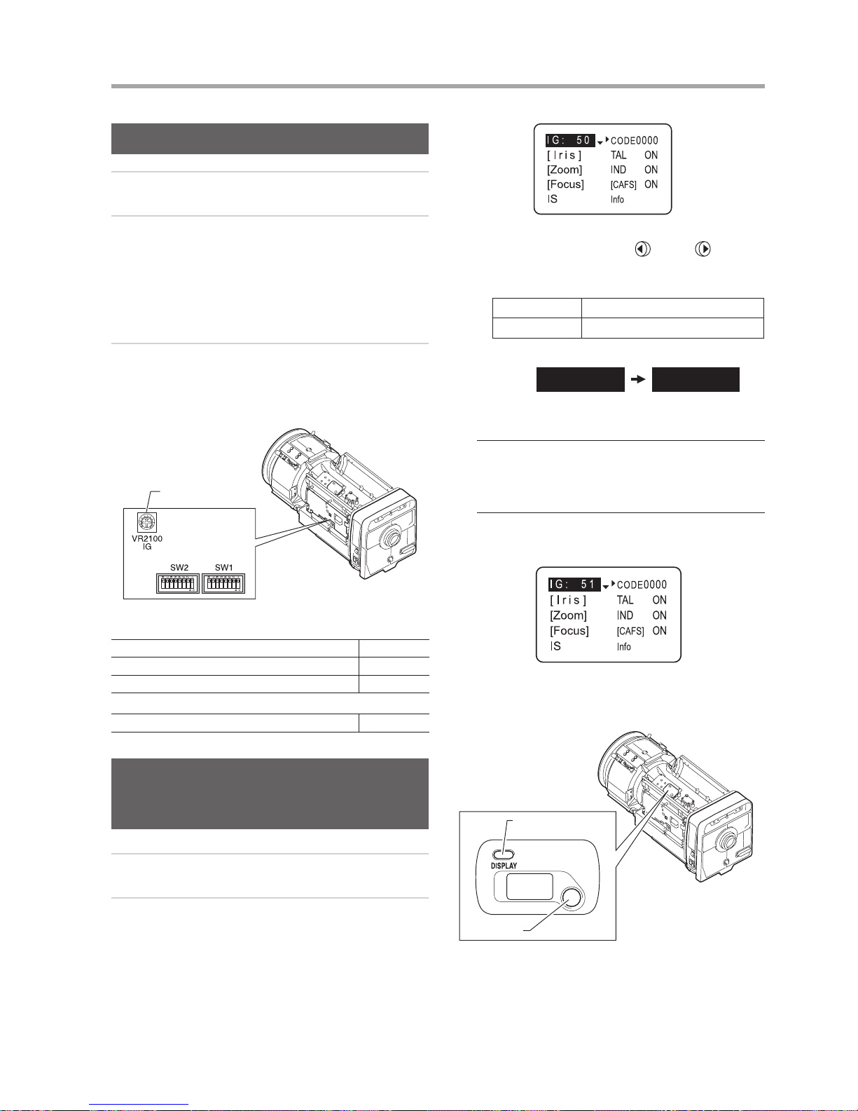
2-4 Iris Gain Adjustment
The iris gain is set to the middle of the adjusting range at
the factory. However, if the iris gain needs to be changed
for some reason, follow the steps below. These steps can
be taken by the trimmer adjustment or on the information
display. (The setting implemented last takes precedence)
* (NOTE)
For other iris adjustment such as iris ends adjustment or video level
adjustment when the extender is used, contact Canon dealer or
your Canon sales representative.
E9
2 PREPARATION
Trimmer Adjustment
1
Remove the lens shroud from the lens body.
2
Check that DIP switch (iris control select switch) is set
to the “OFF” position (refer to the table below).
Depending on the command signals from the camera,
the iris would not be set to auto iris mode although
the switch was set to the “OFF” position. For details,
refer to the “Iris mode” table in 2-5 “Iris Mode Setting
(Option)”.
3
Turn the iris gain adjusting trimmer for the gain
adjustment. To increase the gain, turn the trimmer
clockwise. To decrease the gain, turn the trimmer
counterclockwise.
Iris Gain Adjusting
Trimmer
DIP Switch
IESD/IDSD
XJ100xAF, XJ95x, XJ86xAF, XJ80x, XJ76x, XJ27xAF (SW2) No. 4
XJ100x, XJ86x, XJ75x, XJ72x (SW1) No. 4
XJ60x, XJ27x, XJ23x (SW1) No. 8
IESDA
XJ60x, XJ27x, XJ23x (SW2) No. 4
Making Adjustments on the
Information Display (Only Models
with a Display)
1
Perform “Trimmer Adjustment” steps 1 and 2.
2
Information display operation procedure:
a. Push the DISPLAY switch to bring up the display.
(a)
b. When the screen starts ushing by pushing the
cursor button, move the
(left) or (right)
cursor button until the value to be set appears on
the screen.
Selection item 01 – 99
Function Minimum gain Maximum gain
Default value: 50
I G : 50 I G : 51
(b)
* (NOTE)
• To perform the gain adjustment while checking the iris
operation, set the iris mode of the camera to the [AUTO]
position.
• To determine the maximum gain, set the trimmer at a level
where no hunting occurs.
c. Push the cursor button. This completes the
adjustment.
(c)
For the detailed setting method, refer to the “Display
Operation Manual” at the end of this Operation Manual.
DISPLAY
switch
Information Display
Cursor
button
E10
2 PREPARATION
E11
2-5 Iris Mode Setting (Option)
DIP switch (iris control select switch) was set to the “OFF” position at the factory.
See the table below to nd the relationship between the position of the switch and signals.
Iris mode
Iris control and operation depend on the following three signals
1
Enforced auto iris command signal from the camera system (IRIS ENF)
(Some camera models are not capable to provide this signal.)
2
AUTO/REMOTE iris command signal from the camera system (IRIS A/R)
3
Setting position of DIP switch inside the lens body (Refer to the table under “Trimmer Adjustment” on the previous
page.)
(“ON” position: I.LOCAL/“OFF” position: I.CAMERA However, I.LOCAL may not be usable depending on the
specications.)
The table below lists the relationship between these three signals and iris mode.
Position of the DIP switch
Command signal from camera
Iris Control signal from Iris mode
IRIS ENF IRIS A/R
OFF ON Auto Camera Auto iris
OFF ON Remote Camera Remote iris
OFF OFF Auto Camera Auto iris
OFF OFF Remote Camera Remote iris
ON ON Auto Camera Auto iris
ON ON Remote Camera Remote iris
ON OFF Auto Switch box Remote iris
ON OFF Remote Switch box Remote iris
DIP switch

E11
2 PREPARATION
2-6 Setting on the Information Display
The table below shows the functions that can be set from the information display. For the detailed setting method, refer to
the “Display Operation Manual” at the end of this Operation Manual.
Functions that can be set from the information display
Reference
page in
appendixes
Lens name Lens code setting E4
Initialize operation Initialize operation setting E4
Iris control
Iris gain
Setting the auto iris gain E4, E5
Setting the remote iris gain E5
Setting the iris correction to ON/OFF E5
Setting the iris close detection to ON/OFF E6
Zoom control
Setting the zoom servo start characteristics E6
Setting the zoom servo stop characteristics E6
Setting the zoom mechanism end stop characteristics E6
Preset
Setting the zoom servo start characteristics E7
Setting the zoom servo stop characteristics E7
Setting the analog demand curve characteristics E7
CAM mode settings E8
Setting the servo mode type from the zoom demand E8
Focus control Focus demand curve characteristics E9
Tally
Setting the tally lamp ON/OFF E6
Tally lamp light quantity setting E11
Indicator Setting the indicator ON/OFF E8
CAFS Setting the CAFS ON/OFF E9
IS
IS mechanical lock setting E10
IS operation switch setting E10
IS mode setting E10
Other
Encoder output setting E11
Setting the camera serial communication to ON/OFF E11
Adjusting the Camera Fol Voltage E12
Reset operation Reset to default values E1

E12
2 PREPARATION
2-7 IncorporableFocus
ServoDemand
(Option)
The optional incorporable focus servo demands are offered
for some types of camera.
1
Remove the lens shroud from the lens.
2
Set the focus demand selection switch to the “CAM”
position.
*(NOTE)
This switch is usually set to the “LENS” position by default.
Focus Damand Characteristics Curve
Selection Switch
(Only models without information display)
Information display
Focus Demand Selection Switch
3
Set the focus demand characteristics curve mode on
the informaiton display. One mode can be selected
among the following three curves. For the detailed
setting method, refer to the “DisplayOperation
Manual” at the end of this Operation Manual. Users of
models without the information display can select the
mode with the focus demand characteristics selection
switch.
STD (Standard mode): The Standard mode has the characteristics
where the relationship between the rotation
amount of the control knob and the moving
amount of the focus lens group is almost
in linear.
FAR (Far mode): The Far mode facilitates focusing on an
object in the far end, by making the far end
curve characteristics gentle to increase the
far end resolution.
This mode is useful when shooting an
object in comparatively far distance in
sports events, for example.
NEAR (Near mode): Contrary to the Far mode, the Near mode
facilitates focusing on an object in the
near end, by making the near end curve
characteristics gentle to increase the near
end resolution.
This mode is useful when shooting an
object in a limited space such as a studio.
Innity
Close
range
Focus position
Knob position
Far
mode
Standard
mode
Near mode
E13
3 OPERATION
3-1 Zoom and Focus
Operation
Full-servo System Operation
Zoom and Focus operations are performed based on a
conguration as shown in the gure below.
For the operating procedure, refer to the operation manual
for the respective unit.
① Servo module
② Zoom servo demand
③ Focus servo demand
④ Demand cable
Manual System Operation
Zoom and Focus operations are performed based on a
conguration like that shown in the gure below. For the
operating procedures, refer to the operation manual for the
respective unit.
① Flexible module
② Flexible zoom control unit
③ Flexible focus control unit
④ Flexible cable
⑤ Switch box unit
Semi-servo System Operation
Zoom and Focus operations are performed based on a
conguration like that shown in the gure below.
For the operating procedures, refer to the operation manual
for the respective unit.
① Flexible module
② Flexible focus control unit
③ Servo module
④ Zoom servo demand
⑤ Flexible cable
⑥ Demand cable
 Loading...