


 Loading...
imageRUNNER 2202/2002 Series Service Manual Rev0
|
Product Overview |
|
|
|
|
|
|
|
|
|
|
|
|
|
|
|||||
|
|
Technology |
|
|
|
|
|
|
|
|
|
|
|
|
|
|
|
|||
|
|
|
Periodical Service |
|
|
|
|
|
|
|
|
|
|
|
|
|||||
|
|
|
|
|
|
|
|
|
|
|
|
|
|
|
|
|
||||
|
|
|
|
Parts Replacement and Cleaning |
|
|
|
|||||||||||||
|
|
|
|
|
Adjustment |
|
|
|
|
|
|
|
|
|
|
|
|
|||
|
|
|
|
|
|
Troubleshooting |
|
|
|
|
||||||||||
|
|
|
|
|
|
|
Error Code |
|
|
|
|
|||||||||
|
|
|
|
|
|
|
|
Service Mode |
|
|
|
|
||||||||
|
|
|
|
|
|
|
|
|
Installation |
|
Appendix |
|||||||||
|
1 |
2 |
3 |
4 |
5 |
6 |
7 |
8 |
9 |
|
|
|
|
|
|
|
|
|
|
|
Application
This manual has been issued by Canon Inc. for qualified persons to learn technical theory, installation, maintenance, and repair of products. This manual covers all localities where the products are sold. For this reason, there may be information in this manual that does not apply to your locality.
Corrections
This manual may contain technical inaccuracies or typographical errors due to improvements or changes in products. When changes occur in applicable products or in the contents of this manual, Canon will release technical information as the need arises. In the event of major changes in the contents of this manual over a long or short period, Canon will issue a new edition of this manual.
0-2
The following paragraph does not apply to any countries where such provisions are inconsistent with local law.
Trademarks
The product names and company names used in this manual are the registered trademarks of the individual companies.
Copyright
This manual is copyrighted with all rights reserved. Under the copyright laws, this manual may not be copied, reproduced or translated into another language, in whole or in part, without the consent of Canon Inc.
Copyright CANON INC. 2013
Caution
Use of this manual should be strictly supervised to avoid disclosure of confidential information.
0-2
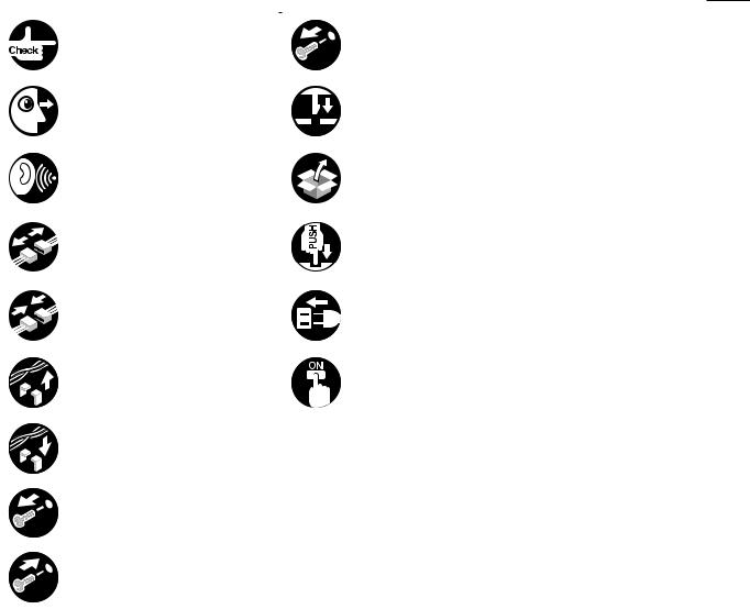
Explanation of Symbols
The following symbols are used throughout this Service Manual.
Symbols |
Explanation |
Symbols |
Explanation |
|
|
|
|
|
Check. |
|
Remove the claw. |
|
Check visually. |
|
Insert the claw. |
|
Check the noise. |
|
Use the bundled part. |
|
Disconnect the connector. |
|
Push the part. |
|
Connect the connector. |
|
Plug the power cable. |
Remove the cable/wire
from the cable guide or wire Turn on the power. saddle.
Set the cable/wire to the cable guide or wire saddle.
Remove the screw.
Tighten the screw.
The following rules apply throughout this Service Manual:
0-3
1.Each chapter contains sections explaining the purpose of specific functions and the relationship between electrical and mechanical systems with reference to the timing of operation.
In the diagrams,  represents the path of mechanical drive; where a signal name accompanies the symbol, the arrow
  indicates the direction of the electric signal.
The expression "turn on the power" means flipping on the power switch, closing the front door, and closing the delivery unit door, which results in supplying the machine with power.
2.In the digital circuits, '1' is used to indicate that the voltage level of a given signal is "High", while '0' is used to indicate "Low". (The voltage value, however, differs from circuit to circuit.) In addition, the asterisk (*) as in "DRMD*" indicates that the DRMD signal goes on when '0'.
In practically all cases, the internal mechanisms of a microprocessor cannot be checked in the field. Therefore, the operations of the microprocessors used in the machines
are not discussed: they are explained in terms of from sensors to the input of the DC controller PCB and from the output of the DC controller PCB to the loads.
The descriptions in this Service Manual are subject to change without notice for product improvement or other purposes, and major changes will be communicated in the form of Service Information bulletins.
All service persons are expected to have a good understanding of the contents of this Service Manual and all relevant Service Information bulletins and be able to identify and isolate faults in the machine
0-3

0
Contents
|
0-5 |
Description of Control Panel------------------------------------------------------------- |
1-12 |
2Technology
0 Safety Precautions
CDRH Act------------------------------------------------------------------------ |
0-7 |
Laser Safety--------------------------------------------------------------------- |
0-7 |
Handling of Laser System--------------------------------------------------- |
0-8 |
Turn power switch ON-------------------------------------------------------- |
0-9 |
Power Supply------------------------------------------------------------------- |
0-9 |
Safety of Toner--------------------------------------------------------------- |
0-10 |
About Toner------------------------------------------------------------------------- |
0-10 |
Toner on Clothing or Skin-------------------------------------------------------- |
0-10 |
Notes When Handling the Lithium and Ni-MH Batteries----------- |
0-10 |
Notes Before it Works Serving------------------------------------------- |
0-10 |
Notes On Assembly/Disassembly--------------------------------------- |
0-11 |
Basic Configuration----------------------------------------------------------- |
2-2 |
Functional Configuration---------------------------------------------------------- |
2-2 |
Basic sequence--------------------------------------------------------------------- |
2-2 |
Basic Operation Sequence--------------------------------------------------------------- |
2-2 |
Original Exposure System--------------------------------------------------- |
2-3 |
Construction------------------------------------------------------------------------- |
2-3 |
Specifications/controls/functions-------------------------------------------------------- |
2-3 |
Major Components-------------------------------------------------------------------------- |
2-3 |
Basic Sequence--------------------------------------------------------------------- |
2-4 |
Basic Sequence at Power-On------------------------------------------------------------ |
2-4 |
Basic Sequence at Start Key ON (book mode/1 original)------------------------- |
2-4 |
Basic Sequence at Start Key ON (ADF mode/1 original)------------------------- |
2-5 |
Controls------------------------------------------------------------------------------- |
2-6 |
Controlling the Scanning Drive System------------------------------------------------ |
2-6 |
CIS (contact image sensor) Outline----------------------------------------- |
2-7 |
1 Product Overview
Product Lineup----------------------------------------------------------------- |
1-2 |
Host machine------------------------------------------------------------------------ |
1-2 |
Option--------------------------------------------------------------------------------- |
1-3 |
Feature--------------------------------------------------------------------------- |
1-4 |
Product feature---------------------------------------------------------------------- |
1-4 |
Specifications------------------------------------------------------------------- |
1-4 |
Product Specifications------------------------------------------------------------- |
1-4 |
Productivity (Print speed)--------------------------------------------------------- |
1-5 |
Paper Type--------------------------------------------------------------------------- |
1-6 |
Pickup------------------------------------------------------------------------------------------ |
1-6 |
Name of Parts------------------------------------------------------------------ |
1-8 |
External View------------------------------------------------------------------------ |
1-8 |
Network model------------------------------------------------------------------------------- |
1-8 |
Local print model---------------------------------------------------------------------------- |
1-9 |
Cross Sectional View------------------------------------------------------------- |
1-10 |
Control Panel----------------------------------------------------------------------- |
1-11 |
Power Switch-------------------------------------------------------------------------------- |
1-11 |
Magnification Change --------------------------------------------------------------------- |
2-8 |
Dust Detection------------------------------------------------------------------------------- |
2-8 |
Image Processing--------------------------------------------------------------------------- |
2-9 |
Service Tasks----------------------------------------------------------------------- |
2-11 |
Periodically Replaced Parts------------------------------------------------------------- |
2-11 |
Consumable Parts------------------------------------------------------------------------- |
2-11 |
Periodical Servicing------------------------------------------------------------------------ |
2-11 |
Action to take when replacing parts--------------------------------------------------- |
2-11 |
Controller System------------------------------------------------------------ |
2-12 |
Overview----------------------------------------------------------------------------- |
2-12 |
Functional Configuration------------------------------------------------------------------ |
2-12 |
Controls------------------------------------------------------------------------------ |
2-13 |
Boot Sequence------------------------------------------------------------------------------ |
2-13 |
Soft Counter--------------------------------------------------------------------------------- |
2-13 |
Fan--------------------------------------------------------------------------------------------- |
2-14 |
Power Supply Control--------------------------------------------------------------------- |
2-14 |
Service Operations---------------------------------------------------------------- |
2-15 |
Periodically Replaced Parts------------------------------------------------------------- |
2-15 |
Consumable Parts ------------------------------------------------------------------------- |
2-15 |
0-5
0

0
Periodical Servicing------------------------------------------------------------------------ |
2-15 |
Action to take when replacing parts--------------------------------------------------- |
2-15 |
Laser Exposure System---------------------------------------------------- |
2-16 |
Construction------------------------------------------------------------------------ |
2-16 |
Specifications/Controls/Functions------------------------------------------------------ |
2-16 |
Main Configuration Parts----------------------------------------------------------------- |
2-16 |
Control System Configuration----------------------------------------------------------- |
2-17 |
Various Control--------------------------------------------------------------------- |
2-18 |
Laser control signal------------------------------------------------------------------------ |
2-18 |
BD signal------------------------------------------------------------------------------------- |
2-18 |
Controlling the Intensity of Laser Light------------------------------------------------ |
2-18 |
Controlling the Polygon Motor----------------------------------------------------------- |
2-18 |
Controlling the Laser Shutter------------------------------------------------------------ |
2-19 |
Service Tasks----------------------------------------------------------------------- |
2-19 |
Periodically Replaced Parts------------------------------------------------------------- |
2-19 |
Consumable Parts------------------------------------------------------------------------- |
2-19 |
Periodical Servicing------------------------------------------------------------------------ |
2-19 |
Action to take when replacing parts--------------------------------------------------- |
2-19 |
Image Formation System-------------------------------------------------- |
2-20 |
Basic Configuration--------------------------------------------------------------- |
2-20 |
Specifications of Image Formation System------------------------------------------ |
2-20 |
Major Components of Image Formation System----------------------------------- |
2-20 |
Image Formation Process---------------------------------------------------------------- |
2-21 |
Basic Sequence-------------------------------------------------------------------- |
2-22 |
Controls------------------------------------------------------------------------------ |
2-23 |
Drum Unit------------------------------------------------------------------------------------- |
2-23 |
Developing Assembly--------------------------------------------------------------------- |
2-24 |
Toner Cartridge----------------------------------------------------------------------------- |
2-25 |
Transfer Unit--------------------------------------------------------------------------------- |
2-26 |
Periodically Replaced Parts------------------------------------------------------------- |
2-27 |
Consumable Parts------------------------------------------------------------------------- |
2-27 |
Periodical Servicing------------------------------------------------------------------------ |
2-27 |
Action to take when replacing parts--------------------------------------------------- |
2-27 |
Fixing System----------------------------------------------------------------- |
2-28 |
Overview----------------------------------------------------------------------------- |
2-28 |
Features-------------------------------------------------------------------------------------- |
2-28 |
Specifications-------------------------------------------------------------------------------- |
2-28 |
Major parts configuration----------------------------------------------------------------- |
2-29 |
|
0-6 |
Controls------------------------------------------------------------------------------ |
2-30 |
Fixing temperature control--------------------------------------------------------------- |
2-30 |
Print temperature control----------------------------------------------------------------- |
2-31 |
Down sequence control------------------------------------------------------------------- |
2-32 |
User mode related to fixing grade------------------------------------------------------ |
2-35 |
Paper loop amount control before fixing---------------------------------------------- |
2-35 |
Protection features------------------------------------------------------------------------- |
2-36 |
Work of Service-------------------------------------------------------------------- |
2-37 |
Periodically Replaced Parts------------------------------------------------------------- |
2-37 |
Consumable Parts------------------------------------------------------------------------- |
2-37 |
Periodical Servicing------------------------------------------------------------------------ |
2-37 |
Action to take when replacing parts--------------------------------------------------- |
2-37 |
Pickup Feed System-------------------------------------------------------- |
2-38 |
Overview----------------------------------------------------------------------------- |
2-38 |
Specification--------------------------------------------------------------------------------- |
2-38 |
Parts Configuration------------------------------------------------------------------------ |
2-38 |
Diagram of Paper Paths------------------------------------------------------------------ |
2-40 |
Controls------------------------------------------------------------------------------ |
2-41 |
Overview-------------------------------------------------------------------------------------- |
2-41 |
Cassette Pickup Assembly--------------------------------------------------------------- |
2-41 |
Multi-Purpose Pickup Assembly-------------------------------------------------------- |
2-44 |
Fixing / Registration Assembly---------------------------------------------------------- |
2-44 |
Duplex / Delivery Assembly-------------------------------------------------------------- |
2-45 |
Detecting Jams----------------------------------------------------------------------------- |
2-46 |
Work of Service-------------------------------------------------------------------- |
2-47 |
Periodically Replaced Parts------------------------------------------------------------- |
2-47 |
Consumable Parts------------------------------------------------------------------------- |
2-47 |
Periodical Servicing------------------------------------------------------------------------ |
2-47 |
Action to take when replacing parts--------------------------------------------------- |
2-47 |
3 Periodical Service |
|
Consumable and Cleaning Parts------------------------------------------ |
3-2 |
4Parts Replacement and Cleaning
List of Parts---------------------------------------------------------------------- |
4-2 |
External View------------------------------------------------------------------------ |
4-2 |
Front Side------------------------------------------------------------------------------------- |
4-2 |
|
0-6 |
0

0
Rear Side-------------------------------------------------------------------------------------- |
4-2 |
Internal View---------------------------------------------------------------------------------- |
4-3 |
List of Main Unit--------------------------------------------------------------------- |
4-4 |
List of Main Unit(1/2)----------------------------------------------------------------------- |
4-4 |
List of Main Unit(2/2)----------------------------------------------------------------------- |
4-5 |
List of periodically replacement parts, consumable parts and locations |
|
for cleaning--------------------------------------------------------------------------- |
4-6 |
PCB------------------------------------------------------------------------------------ |
4-7 |
Solenoid------------------------------------------------------------------------------- |
4-7 |
Sensor--------------------------------------------------------------------------------- |
4-8 |
Motor----------------------------------------------------------------------------------- |
4-9 |
FAN------------------------------------------------------------------------------------ |
4-9 |
Switch-------------------------------------------------------------------------------- |
4-10 |
Clutch--------------------------------------------------------------------------------- |
4-10 |
Others-------------------------------------------------------------------------------- |
4-11 |
External Covers-------------------------------------------------------------- |
4-12 |
Removing the Front Cover------------------------------------------------------ |
4-12 |
Removing the Rear Cover------------------------------------------------------- |
4-13 |
Removing the Left Cover Unit-------------------------------------------------- |
4-13 |
Removing the Reader Rear Cover-------------------------------------------- |
4-14 |
Removing the Right Cover------------------------------------------------------ |
4-15 |
Removing the Reader Front Cover------------------------------------------- |
4-16 |
Removing the Cassette 1-------------------------------------------------------- |
4-16 |
Removing the Control Panel Unit---------------------------------------------- |
4-17 |
Removing the Right Front Cover---------------------------------------------- |
4-18 |
Removing the Delivery Tray Cover-------------------------------------------- |
4-18 |
Removing the Left Front Cover------------------------------------------------ |
4-19 |
Removing the Front Inner Cover---------------------------------------------- |
4-20 |
Original Exposure System------------------------------------------------- |
4-21 |
Removing the CIS Unit----------------------------------------------------------- |
4-21 |
Adjustment for the Reader Upper Unit Replacement----------------------------- |
4-24 |
Removing the Reader Unit------------------------------------------------------ |
4-26 |
Controller System------------------------------------------------------------ |
4-27 |
Removing the Controller PCB-------------------------------------------------- |
4-27 |
Adjustment for the Controller PCB replacement----------------------------------- |
4-28 |
Removing the HVT PCB--------------------------------------------------------- |
4-30 |
|
|
0-7 |
|
Removing the Fixing Cooling Fan--------------------------------------------- |
4-30 |
|
Laser Exposure System---------------------------------------------------- |
4-34 |
|
Removing the Laser Scanner Unit-------------------------------------------- |
4-34 |
|
Image Formation System-------------------------------------------------- |
4-35 |
|
Removing the Toner Cartridge------------------------------------------------- |
4-35 |
|
Removing the Drum Unit-------------------------------------------------------- |
4-35 |
|
Removing the Developing Assembly----------------------------------------- |
4-36 |
|
Removing the Developing Cylinder------------------------------------------- |
4-37 |
|
Removing the Transfer Roller-------------------------------------------------- |
4-39 |
|
Fixing System----------------------------------------------------------------- |
4-40 |
|
Removing the Fixing Assembly------------------------------------------------ |
4-40 |
|
Removing the Fixing Film Unit------------------------------------------------- |
4-42 |
|
Removing the Pressure Roller------------------------------------------------- |
4-44 |
|
Pickup Feed System-------------------------------------------------------- |
4-46 |
|
Removing the Multi-purpose Tray Pickup Roller--------------------------- |
4-46 |
|
Removing the Multi-purpose Tray Separation Pad------------------------ |
4-47 |
|
Removing the Cassette 1 Separation Pad---------------------------------- |
4-48 |
|
Removing the Cassette 1 Pickup Roller------------------------------------- |
4-49 |
|
Removing the Cassette 1 Feed Roller--------------------------------------- |
4-51 |
|
Removing the Main Drive Unit------------------------------------------------- |
4-52 |
|
Removing the Registration Roller--------------------------------------------- |
4-54 |
5 |
Adjustment |
|
|
Outline---------------------------------------------------------------------------- |
5-2 |
|
Adjustment When Replacing Parts--------------------------------------------- |
5-2 |
|
Image Position Adjustment------------------------------------------------------- |
5-2 |
|
Adjustment When Replacing Parts---------------------------------------- |
5-3 |
|
Scanning System------------------------------------------------------------------- |
5-3 |
|
Adjustment for the CIS Unit Replament----------------------------------------------- |
5-3 |
|
Adjustment for the Controller PCB replacement------------------------------------ |
5-5 |
|
Image Position Adjustment-------------------------------------------------- |
5-6 |
|
Leading Edge Margin Adjustment---------------------------------------------- |
5-6 |
|
Left Edge Margin Adjustment (Front Side)----------------------------------- |
5-6 |
|
Left Edge Margin Adjustment (Reverse Side)------------------------------- |
5-7 |
6 |
Troubleshooting |
|
|
|
0-7 |
0

0
0-8
Initial Check--------------------------------------------------------------------- |
6-2 |
Initial check items list-------------------------------------------------------------- |
6-2 |
Test Print------------------------------------------------------------------------- |
6-3 |
Overview------------------------------------------------------------------------------ |
6-3 |
Select the test print TYPE-------------------------------------------------------- |
6-3 |
Troubleshooting items-------------------------------------------------------- |
6-4 |
Error Code Details------------------------------------------------------------------ |
7-3 |
Jam Code------------------------------------------------------------------------ |
7-6 |
Main Unit (Included with the Cassette Feeding Module-AB1 and the |
|
Duplex Unit-C1)--------------------------------------------------------------------- |
7-6 |
DADF-AM1--------------------------------------------------------------------------- |
7-7 |
Alarm Code---------------------------------------------------------------------- |
7-8 |
Troubleshooting items list-------------------------------------------------------- |
6-4 |
Alarm Code Details---------------------------------------------------------------- |
7-8 |
|
Image Failure------------------------------------------------------------------------ |
6-4 |
8 Service Mode |
|
|
Scattered image at center----------------------------------------------------------------- |
6-4 |
|
||
Paper Reverse Side Stained with Toner----------------------------------------------- |
6-5 |
Outline---------------------------------------------------------------------------- |
8-2 |
|
Stained Leading/Trailing Edge of Paper ---------------------------------------------- |
6-5 |
Outline of Service Mode |
8-2 |
|
Image Transfer Wrong/Text Void |
6-6 |
|||
Backing up Service Mode |
8-2 |
|||
White Dot at Reverse Trailing Edge of HT |
6-6 |
|||
Screen flow of Service Mode |
8-3 |
|||
Irregular Transfer Roller Pitch (50mm) |
6-7 |
|||
Screen flow of Service mode |
8-3 |
|||
Operation failure |
6-7 |
|||
COPIER |
8-4 |
|||
Too Large Curl |
6-7 |
|||
DISPLAY |
8-4 |
|||
Paper Jam due to Solid Image Printed on the Paper with Small Leading-Edge |
||||
VERSION |
8-4 |
|||
Margin (1-4 mm) |
6-8 |
|||
CCD |
8-4 |
|||
"Set the drum" Indication |
6-8 |
|||
SPDTYPE |
8-6 |
|||
Special mode (User mode) |
6-9 |
|||
I/O |
8-7 |
|||
Upgrading Targets and Procedure |
6-10 |
|||
R-CON |
8-7 |
|||
Outline |
6-10 |
|||
FEEDER |
8-7 |
|||
Preparation |
6-10 |
|||
ADJUST |
8-7 |
|||
System Requirements |
6-10 |
|||
ADJ-XY |
8-7 |
|||
Preparation |
6-10 |
|||
CCD |
8-9 |
|||
Downloading System Software |
6-11 |
|||
FEED-ADJ |
8-9 |
|||
Log Collector |
6-13 |
|||
FIXING |
8-10 |
|||
OutLine |
6-13 |
|||
LASER |
8-11 |
|||
Scope of Application |
6-13 |
|||
FUNCTION |
8-11 |
|||
What to Prepare |
6-13 |
|||
CCD |
8-11 |
|||
Operation Procedure |
6-13 |
|||
CLEAR |
8-12 |
|||
Troubleshooting |
6-13 |
|||
MISC-R |
8-13 |
|||
|
|
|||
7 Error Code |
|
MISC-P---------------------------------------------------------------------------------------- |
8-13 |
|
|
SYSTEM-------------------------------------------------------------------------------------- |
8-13 |
||
Overview------------------------------------------------------------------------- |
7-2 |
SPLMAN-------------------------------------------------------------------------------------- |
8-13 |
|
Outline--------------------------------------------------------------------------------- |
7-2 |
INSTALL-------------------------------------------------------------------------------------- |
8-14 |
|
Error Code----------------------------------------------------------------------- |
7-3 |
PART-CHK----------------------------------------------------------------------------------- |
8-14 |
|
|
|
|
0-8 |
|
0

0
OPTION------------------------------------------------------------------------------ |
8-14 |
BODY------------------------------------------------------------------------------------------ |
8-14 |
USER------------------------------------------------------------------------------------------ |
8-17 |
COUNTER-------------------------------------------------------------------------- |
8-18 |
TOTAL----------------------------------------------------------------------------------------- |
8-18 |
PICK-UP-------------------------------------------------------------------------------------- |
8-19 |
FEEDER-------------------------------------------------------------------------------------- |
8-19 |
JAM-------------------------------------------------------------------------------------------- |
8-19 |
FEEDER----------------------------------------------------------------------- |
8-21 |
ADJUST------------------------------------------------------------------------------ |
8-21 |
FUNCTION-------------------------------------------------------------------------- |
8-22 |
TEST MODE------------------------------------------------------------------ |
8-23 |
PRINT-------------------------------------------------------------------------------- |
8-23 |
9 Installation
How to check this Installation Procedure-------------------------------- |
9-2 |
When Using the parts included in the package----------------------------- |
9-2 |
Symbols in the Illustration-------------------------------------------------------- |
9-2 |
Making Pre-Checks----------------------------------------------------------- |
9-2 |
Selecting the Site of Installation------------------------------------------------ |
9-2 |
Type of Model----------------------------------------------------------------------- |
9-3 |
Points to Make Before Installation----------------------------------------- |
9-3 |
Checking the Contents------------------------------------------------------- |
9-4 |
Unpacking and Installation Procedure------------------------------------ |
9-5 |
Unpacking the Machine and Removing the Packaging Materials------ |
9-5 |
Installing the Toner Cartridge---------------------------------------------------- |
9-6 |
Setting the Cassettes-------------------------------------------------------------- |
9-8 |
Connecting the cord--------------------------------------------------------------- |
9-9 |
Turning ON the Main Power / Stirring Toner / Initial setting-------------- |
9-9 |
Setting the Date and Time------------------------------------------------------- |
9-10 |
Checking the Operation and the Print Image ------------------------------ |
9-10 |
About the USB Cable (for Network Model )--------------------------------- |
9-10 |
About the LAN Cable (for Network Model of Asia, Korea and Taiwan)---- |
|
9-10 |
|
Checking the Connection to the Network (for Network Model )------- |
9-10 |
Platen Cover Type-T Installation Procedure ------------------------- |
9-11 |
|
0-9 |
Check the Contents--------------------------------------------------------------- |
9-11 |
Main Power Switch OFF--------------------------------------------------------- |
9-11 |
Installation Outline Drawing----------------------------------------------------- |
9-11 |
Installation Procedure------------------------------------------------------------ |
9-11 |
Heater Kit-M1 Installation Procedure ---------------------------------- |
9-13 |
Checking the Contents----------------------------------------------------------- |
9-13 |
Main Power Switch OFF--------------------------------------------------------- |
9-13 |
Installation Outline Drawing----------------------------------------------------- |
9-13 |
Product Name --------------------------------------------------------------------- |
9-13 |
Preparation of the Host Machine---------------------------------------------- |
9-14 |
Connecting Heater Kit-M1 with the Host Machine------------------------ |
9-15 |
After Installing the Heater Kit--------------------------------------------------- |
9-17 |
Cassette Heater Unit-40 Installation Procedure--------------------- |
9-18 |
Checking the Contents----------------------------------------------------------- |
9-18 |
Main Power Switch OFF--------------------------------------------------------- |
9-18 |
Installation Outline Drawing----------------------------------------------------- |
9-18 |
Points to Note Before Installation---------------------------------------------- |
9-18 |
Connecting Cassette Heater Unit-40 with the Host Machine----------- |
9-19 |
Connect Cassette Heater Unit-40 with Cassette Feeding Module |
|
AB1(Option Cassette)------------------------------------------------------------ |
9-20 |
After Installing the Heater------------------------------------------------------- |
9-21 |
Appendix
Service Tools------------------------------------------------------------------ |
10-2 |
Special Tools-------------------------------------------------------------------------------- |
10-2 |
Oils and Solvents--------------------------------------------------------------------------- |
10-2 |
General Circuit Diagram--------------------------------------------------- |
10-3 |
General Circuit Diagram--------------------------------------------------------- |
10-3 |
General Circuit Diagram (1/5)----------------------------------------------------------- |
10-3 |
General Circuit Diagram (2/5)----------------------------------------------------------- |
10-4 |
General Circuit Diagram (3/5)----------------------------------------------------------- |
10-5 |
General Circuit Diagram (4/5)----------------------------------------------------------- |
10-6 |
General Circuit Diagram (5/5)----------------------------------------------------------- |
10-7 |
General Timing Chart------------------------------------------------------- |
10-8 |
2 Prints, Continuous, Cassette 1---------------------------------------------- |
10-8 |
Backup Data------------------------------------------------------------------ |
10-9 |
|
0-9 |
0

0
0-10
Soft Counter Specifications--------------------------------------------- |
10-10 |
Soft counter specifications---------------------------------------------------- |
10-10 |
0-10
0

Safety Precautions
■■CDRH Act
■■Laser Safety ■■Handling of Laser System ■■Turn power switch ON ■■Power Supply
■■Safety of Toner ■■Notes When Handling
the Lithium and Ni-MH Batteries
■■Notes Before it Works Serving
0Safety Precautions > Laser Safety
CDRH Act
The Center for Devices and Radiological Health of the US Food and Drug Administration put into force regulations concerning laser products on August 2, 1976. These regulations apply to laser products manufactured on and after August 1, 1976, and the sale of laser products not certified under the regulations is banned within the Untied States. The label shown here indicates compliance with the CDRH regulations, and its attachment is required on all laser products that are soled in the United States.
CANON INC.
30-2,SHIMOMARUKO,3-CHOME,OHTA-KU,TOKYO,JAPAN
MANUFACTURED:
THIS PRODUCT CONHORMS WITH DHHS RADIATION
PERFORMANCE STANDARD 21CFR CHAPTER 1
SUBCHAPTER J.
F-0-1
0-12
Laser Safety
Laser beam radiation may pose a danger to the human body. A laser scanner mounted on the machine is sealed with the protection housing and external cover to prevent the laser beam from leaking to the outside. The laser beam never leaks out of the scanner as far as users operate the machine normally.
The following warnings are given to comply with Safety Standard (EN60950-1).
Sicherheit des Lasers
Laserstrahlen können für den menschlichen Körper gefährlich sein. Aus diesem Grund ist das optische Lasersystem mit einem Schutzgehäuse und einer Außenabdeckung
dicht verschlossen und hat eine Struktur, die keine Laserstrahlen nach außen dringen lässt. Unter der Voraussetzung, dass der Benutzer dieses Gerät normal
bedient, ist ein Austritt von Laserstrahlen daher ausgeschlossen.
A different description may be used for a different product.
0-12
0Safety Precautions > Laser Safety

0Safety Precautions > Handling of Laser System
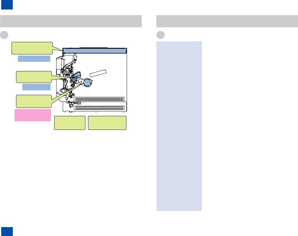
Handling of Laser System
When servicing the area around the laser assembly, be sure to turn off the main power. If you must servicr while the power is turned on, be sure to keep the followings:
-Do not use a screwdriver or tools that have a high level of reflectance in the laser path.
-Remove watches and rings before starting the work. (They can reflect the laser beam, possibly hitting the eye.)
The machine's covers that can reflect laser light are identified by means of a warning label (Figure). If you must detach a cover showing the label, be sure to take
extra caution during the work.
The following warnings are given to comply with Safety Standard (EN60950-1).
F-0-2
0-13
F-0-3
This product is certificated as a Class 1 laser product under IEC60825-1:2007.
0-13
0Safety Precautions > Handling of Laser System

0Safety Precautions > Power Supply
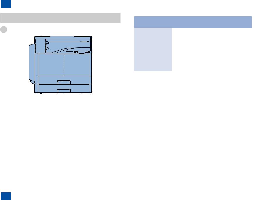
Turn power switch ON
The machine is equipped with 2 power switches: main power switch and energy saver key. The machine goes on when the main power switch is turned on (i.e., other than in low power mode, sleep mode).
Energy Saver Key
Main Power Switch
F-0-4
0-14
Power Supply
1.As a general rule, do not use extension cords. Using an extension cord may result in a fire or electrical shock. If an extension cord must be used, however, use one for local rated voltage and over, untie the cord binding, and insert the power plug completely into the extension cord outlet to ensure a firm connection between the power cord and the extension cord.
2.The socket-outlet shall be installed near the equipment and shall be easily accessible.
F-0-5
0-14
0Safety Precautions > Power Supply
0Safety Precautions > Notes Before it Works Serving
Safety of Toner
Do not throw toner into fire. It may cause explosion.
Toner on Clothing or Skin
•If your clothing or skin has come into contact with toner, wipe it off with tissue; then, wash it off with water.
•Do not use warm water, which will cause the toner to jell and fuse permanently with the fibers of the cloth.
•Tonner is easy to react with plastic material, avoid contact with plastic.
0-15
Notes When Handling the Lithium and Ni-MH
RISK OF EXPLOSION IF BATTERY IS REPLACED BY AN INCORRECT TYPE. DISPOSE OF USED BATTERIES ACCORDING TO THE INSTRUCTIONS.
Wenn mit dem falschen Typ ausgewechselt, besteht Explosionsgefahr.
At servicing, be sure to turn OFF the power source according to the specified steps and disconnect the power plug.
0-15
0Safety Precautions > Notes Before it Works Serving

0 Safety Precautions > Notes On Assembly/Disassembly
0-16
Notes On Assembly/Disassembly
Follow the items below to assemble/disassemble the device.
1.Disconnect the power plug to avoid any potential dangers during assembling/disassembling works.
2.If not specially instructed, reverse the order of disassembly to reinstall.
3.Ensure to use the right screw type (length, diameter, etc.) at the right position when assembling.
4.To keep electric conduction, binding screws with washers are used to attach the grounding wire and the varistor. Ensure to use the right screw type when assembling.
5.Unless it is specially needed, do not operate the device with some parts removed.
6.Never remove the paint-locked screws when disassembling.
F-0-6
ACHTUNG
Zweipolige bzw. Neutralleiter-Sicherung
F-0-7
0-16
0Safety Precautions > Notes On Assembly/Disassembly

1Product Overview■■Product Lineup
■■Feature ■■Specifications ■■Name of Parts
1Product Overview
1Product Overview > Product Lineup > Host machine
Product Lineup
Host machine
F-1-1
|
|
|
|
|
|
1-2 |
|
|
|
|
|
|
|
|
|
|
|
iR2202 |
iR2002 |
|
|||
|
|
Network model |
Local print |
Network model |
|
Local print |
|
|
|
|
model |
|
|
model |
|
Print Speed |
|
22ppm |
20ppm |
|
|||
Positioning |
|
Target machine: |
iR2422/2420 Series |
|
|
||
LAN Port |
|
Yes |
- |
Yes |
|
- |
|
USB Port |
|
Yes |
Yes |
Yes |
|
Yes |
|
Option |
ADF |
Yes |
- |
Yes |
|
- |
|
Conversion |
Duplex Unit |
Yes |
- |
Yes |
|
- |
|
|
Cassette |
Yes |
- |
Yes |
|
- |
|
|
Feeding |
|
|
|
|
|
|
|
Module |
|
|
|
|
|
|
|
Cassette |
Yes |
Yes |
Yes |
|
Yes |
|
|
Heater |
|
|
|
|
|
|
|
|
|
|
|
|
T-1-1 |
|
1-2
1Product Overview > Product Lineup > Host machine

1Product Overview > Product Lineup > Option
Option
Platen Cover Type T
DADF-AM1
Heater Kit-M1
Cassette Heater Unit-40
Duplex Unit-C1
FL Cassette-AU1
Cassette Feeding
Module-AB1
F-1-2
1-3
Product name |
Required options, conditions, etc. |
DADF-AM1 |
Opiton for network model |
|
Paper weight: |
|
<Single feed> 37 to 128 g/m2 |
|
<Continuous feed> 52 to 105 g/m2 |
|
Stacking capacity: |
|
50 sheets (80 g/m2, A4 or LTR) |
Platen Cover Type T |
Standard or option |
Cassette Feeding Module-AB1 |
Opiton for network model |
|
Standard or option |
|
Pickup capacity: 250 sheets (80 g/m2) |
FL Cassette-AU1 |
Option for 1st cassette of the main body |
Duplex Unit-C1 |
Opiton for network model |
|
Standard or option |
Heater Kit-M1 |
Heater Kit-M1 is required when installing the optional |
|
heater. |
Cassette Heater Unit-40 |
Option for cassette of main body and Cassette Feeding |
|
Module-AB1. |
|
Use it to suppress the moisture absorption of the paper in |
|
the cassette. |
|
Heater Kit-M1 is required. |
|
T-1-2 |
1-3
1Product Overview > Product Lineup > Option
1Product Overview > Specifications > Product Specifications
Feature
Product feature
Reader unit
- The mold frame was adopted.
Drum unit
-Installed at the time of factory shipment.
-The toner of the low melting was adopted.
Paper loading improvement (High-temperature high-humidity
Controller PCB |
Main body frame |
|||
- The DC |
- The mold frame was adopted. |
|||
the main |
|
|
|
|
were unified. |
|
|
|
|
|
|
|
|
|
|
Space-saving |
|
Small-size/weight-saving |
|
|
|
|
|
|
F-1-3
1-4
Specifications
Product Specifications
Copyboard |
Stream reading, original fixed reading |
Body |
Desktop |
Light source type |
LED (RGB) |
Photosensitive medium |
OPC drum (30 mm dia) |
Image reading method |
CIS |
Reproduction method |
Indirect electrostatic method |
Exposure method |
Laser exposure system |
Charging method |
Roller charge |
Development method |
Dry single component projection developing |
Transfer method |
By transfer roller |
Separation method |
Curvature and static eliminator |
Pickup method |
1st cassette: Pad separation method |
|
2nd cassette: Retard separation method |
|
Multi-purpose pickup tray: Pad separation method |
Fixing method |
On demand |
Delivery method |
Face down delivery (in-body delivery) |
Reproduction ratio |
25 to 400% |
Drum cleaning method |
By cleaning blade |
Toner type |
Single component magnetic negative charge toner |
Toner replenish method |
Toner cartridge |
Toner level detection function |
Yes |
Top image margin |
3.0 ± 1.5 mm |
Left image margin |
3.0 ± 2.0 mm |
Warm-up time |
At power ON: 13 sec or less |
Number of gradations |
256 gradations |
Reading resolution |
600 x 600 dpi |
Writing resolution |
600 x 600 dpi |
First print time |
7.9 sec or less |
Paper type (Cassette) |
Plain paper (64 to 90 g/m2), recycled paper (64 to 80 g/m2), color |
|
paper (64 to 80 g/m2), pre-punched paper |
Paper type (Multi-purpose |
Plain paper (64 to 90 g/m2), recycled paper (64 to 80 g/m2), color |
pickup tray) |
paper (64 to 80 g/m2), pre-punched paper, bond paper(75 to 90 g/ |
|
m2), heavy paper 1 (91 to 105 g/m2), heavy paper 2 (106 to 128 g/ |
|
m2), OHP, labels, Envelopes (No.10(COM10), Monarch, ISO-C5, |
|
DL) |
Paper size (Cassette 1) |
A4, A4R, A3, A5R, B4, B5, B5R, LTR, LTRR, LGL, 11" x 17" (279 |
|
mm X 432 mm), STMTR, 8K, 16K, 16KR |
Paper size (Cassette 2) |
A4, A4R, A3, A5, B4, B5, B5R, LTR, LTRR, LGL, 11" x 17" (279 |
|
mm X 432 mm), STMT, 8K, 16K, 16KR |
1-4
1Product Overview > Specifications > Product Specifications

1Product Overview > Specifications > Productivity (Print speed)
Paper size (Multi-purpose |
A4, A4R, A3, A5, A5R, B4, B5, B5R, LTR, LTRR, LGL, 11" x 17" |
|
pickup tray) |
|
(279 mm X 432 mm), STMT, STMTR, EXEC, 8K, 16K, 16KR, |
|
|
Custom paper size (95 x 148 mm to 297 x 431.8 mm), Envelopes |
|
|
(No.10(COM10), Monarch, ISO-C5, DL) |
Pickup capacity |
Cassette1/2: 250 sheets (80 g/m2) |
|
|
|
Multi-purpose pickup tray: 80 sheets (80 g/m2) |
Duplex method |
Through path duplex |
|
Noise |
|
imageRUNNER 2202: |
|
|
At the time of printing: 66.7 dB or less / At the time of standby: 48 |
|
|
dB or less |
|
|
imageRUNNER 2002: |
|
|
At the time of printing: 66 dB or less / At the time of standby: 48 |
|
|
dB or less |
Ozone |
|
1.5 mg/h or smaller |
Power supply rating |
Network model |
|
|
|
120 - 127 V AC, 60Hz, 4.6 A |
|
|
220 - 240 V AC, 50Hz/60Hz, 2.7 A |
|
|
Local print model |
|
|
220 - 240 V AC, 50Hz/60Hz, 2.4 A |
Power |
Maximum |
1.5 kW or less |
consumption |
power |
|
|
consumption |
|
|
At the time of |
Network model |
|
printing |
imageRUNNER 2202 : Approx. 470 Wh (Reference) |
|
|
imageRUNNER 2002 : Approx. 433 Wh (Reference) |
|
|
Local print model |
|
|
imageRUNNER 2202 : Approx. 416 Wh (Reference) |
|
|
imageRUNNER 2002 : Approx. 398 Wh (Reference) |
|
At the time of |
2.0 W or less |
|
sleep (Deep |
|
|
Sleep) |
|
Dimensions (W x D x H) |
622 mm x 589 mm x 502 mm (with the platen cover and single |
|
|
|
cassette) |
|
|
622 mm x 589 mm x 567 mm (with the platen cover and double |
|
|
cassette) |
|
|
622 mm x 589 mm x 692 mm (with the feeder and double |
|
|
cassette) |
Weight |
|
Min (With the platen cover and single cassette: 29.7 kg (included |
|
|
with the drum unit and toner cartridge) |
|
|
Max (with the feeder and double cassette): 41.3 kg (included with |
|
|
the drum unit and toner cartridge) |
|
|
|
|
|
T-1-3 |
1-5
Productivity (Print speed)
Fixing mode |
Size |
1-sided |
2-sided |
|
||
|
|
Cassette |
Multi- |
Cassette |
Multi- |
|
|
|
pickup |
purpose |
pickup |
purpose |
|
|
|
|
pickup |
|
pickup |
|
Plain paper mode |
A3, 11" x 17" |
iR2202: 11 |
10 |
iR2202: 6.9 |
iR2202: 6.9 |
|
(color paper, |
(279 mm X 432 |
iR2002: 10 |
|
iR2002: 6.7 |
iR2002: 6.7 |
|
recycled paper, |
mm) |
|
|
|
|
|
plain paper (64 |
A4, LTR, 16K |
iR2202: 22 |
20 |
iR2202: 14.7 |
iR2202: 14.7 |
|
to 90 g/m2), pre- |
|
iR2002: 20 |
|
iR2002: 14.2 |
iR2002: 14.2 |
|
punched paper) |
B4, LGL, 8K |
10 |
10 |
6.7 |
6.7 |
|
B5, EXEC |
20 |
20 |
14 .2 |
14 .2 |
|
|
|
|
|||||
|
A4R, LTRR |
11 |
11 |
7.8 |
7.8 |
|
|
A5, STMT |
23 |
23 |
- |
- |
|
|
A5R, B5R, |
13 |
13 |
9.1 |
9.1 |
|
|
STMTR, 16KR |
|
|
|
|
|
|
Custom paper |
5 |
5 |
- |
- |
|
|
size |
|
|
|
|
|
Heavy paper L |
A3, 11" x 17" |
- |
8 |
- |
- |
|
mode (heavy |
(279 mm X 432 |
|
|
|
|
|
paper 1 (91 to |
mm) |
|
|
|
|
|
105 g/m2), label) |
A4, LTR, 16K |
- |
12 |
- |
- |
|
|
B4, LGL, 8K |
- |
8 |
- |
- |
|
|
B5, EXEC |
- |
12 |
- |
- |
|
|
A4R, LTRR |
- |
10 |
- |
- |
|
|
A5, STMT |
- |
13 |
- |
- |
|
|
A5R, B5R, |
- |
10 |
- |
- |
|
|
STMTR, 16KR |
|
|
|
|
|
|
Custom paper |
- |
5 |
- |
- |
|
|
size |
|
|
|
|
|
Heavy paper |
A3, 11" x 17" |
- |
7 |
- |
- |
|
mode (Heavy |
(279 mm X 432 |
|
|
|
|
|
paper 2 (106 to |
mm) |
|
|
|
|
|
128 g/m2)) |
A4, LTR, 16K |
- |
10 |
- |
- |
|
|
B4, LGL, 8K |
- |
6 |
- |
- |
|
|
B5, EXEC |
- |
10 |
- |
- |
|
|
A4R, LTRR |
- |
8 |
- |
- |
|
|
A5, STMT |
- |
11 |
- |
- |
|
|
A5R, B5R, |
- |
7 |
- |
- |
|
|
STMTR, 16KR |
|
|
|
|
|
|
Custom paper |
- |
5 |
- |
- |
|
|
size |
|
|
|
|
|
|
|
|
|
|
1-5 |
|
1Product Overview > Specifications > Productivity (Print speed)
1Product Overview > Specifications > Paper Type > Pickup
Fixing mode |
Size |
1-sided |
2-sided |
||
|
|
Cassette |
Multi- |
Cassette |
Multi- |
|
|
pickup |
purpose |
pickup |
purpose |
|
|
|
pickup |
|
pickup |
Super heavy |
A3, 11" x 17" |
- |
5 |
- |
- |
paper mode |
(279 mm X 432 |
|
|
|
|
(Bond paper (75 |
mm) |
|
|
|
|
to 90 g/m2)) |
A4, LTR, 16K |
- |
7 |
- |
- |
|
B4, LGL, 8K |
- |
5 |
- |
- |
|
B5, EXEC |
- |
6 |
- |
- |
|
A4R, LTRR |
- |
4 |
- |
- |
|
A5, STMT |
- |
5 |
- |
- |
|
A5R, B5R, |
- |
4 |
- |
- |
|
STMTR, 16KR |
|
|
|
|
|
Custom paper |
- |
3 |
- |
- |
|
size |
|
|
|
|
Envelope |
Monarch |
- |
4 |
- |
- |
|
COM10 |
- |
4 |
- |
- |
|
ISO-C5 |
- |
4 |
- |
- |
|
DL |
- |
4 |
- |
- |
OHP |
A4R |
- |
11 |
- |
- |
|
LTRR |
- |
11 |
- |
- |
T-1-4
1-6
Paper Type
Following shows the types of usable papers.
See the table below for the custom paper size.
Type |
|
|
Feeding direction (mm) |
|
Width direction (mm) |
|||
Custom paper size |
|
148 to 431.8 |
|
|
|
95 to 297 |
||
|
|
|
|
|
|
|
T-1-5 |
|
■■Pickup |
|
|
|
|
|
|
|
|
Usable paper types are shown. |
|
|
|
|
|
|
||
|
|
|
|
|
|
|||
Paper type |
Size |
Multi-purpose |
Cassette 1 |
Cassette 2 |
|
|||
|
|
|
pickup tray |
|
|
|
|
|
Color paper, |
A3 |
Yes |
|
Yes |
Yes |
|
||
recycled paper, |
|
|
|
|
|
|
||
B4 |
Yes |
|
Yes |
Yes |
|
|||
plain paper (64 to |
|
|
|
|
|
|
||
A4R |
Yes |
|
Yes |
Yes |
|
|||
90 g/m2) |
|
|
|
|
|
|
|
|
A4 |
Yes |
|
Yes |
Yes |
|
|||
|
|
|
||||||
|
B5R |
Yes |
|
Yes |
Yes |
|
||
|
B5 |
Yes |
|
Yes |
Yes |
|
||
|
A5 |
Yes |
|
No |
Yes |
|
||
|
A5R |
Yes |
|
Yes |
No |
|
||
|
11" x 17" (279 |
|
|
|
|
|
|
|
|
mm X 432 |
Yes |
|
Yes |
Yes |
|
||
|
mm) |
|
|
|
|
|
|
|
|
LGL |
Yes |
|
Yes |
Yes |
|
||
|
LTR |
Yes |
|
Yes |
Yes |
|
||
|
LTRR |
Yes |
|
Yes |
Yes |
|
||
|
STMTR |
Yes |
|
Yes |
No |
|
||
|
STMT |
Yes |
|
No |
Yes |
|
||
|
EXEC |
Yes |
|
No |
No |
|
||
|
K8 |
Yes |
|
Yes |
Yes |
|
||
|
K16 |
Yes |
|
Yes |
Yes |
|
||
|
K16R |
Yes |
|
Yes |
Yes |
|
||
|
Custom paper |
Yes |
|
No |
No |
|
||
|
size |
|
|
|||||
|
|
|
|
|
|
|
||
1-6
1Product Overview > Specifications > Paper Type > Pickup

|
1 |
Product Overview > Specifications > Paper Type > Pickup |
1-7 |
||||
|
|
|
|
|
|
||
|
|
|
|
|
|
|
|
|
Paper type |
Size |
Multi-purpose |
Cassette 1 |
Cassette 2 |
|
|
|
|
|
|
pickup tray |
|
|
|
Heavy paper 1 |
A3 |
Yes |
No |
No |
|
||
(91 to 105 g/m2), |
B4 |
Yes |
No |
No |
|
||
heavy paper 2 |
A4R |
Yes |
No |
No |
|
||
(106 to 128 g/ |
A4 |
Yes |
No |
No |
|
||
m2), bond paper |
B5R |
Yes |
No |
No |
|
||
(75 to 90 g/m2) |
B5 |
Yes |
No |
No |
|
||
A5 |
Yes |
No |
No |
|
|||
|
|
|
|
||||
|
|
|
A5R |
Yes |
No |
No |
|
|
|
|
11" x 17" (279 |
|
|
|
|
|
|
|
mm X 432 |
Yes |
No |
No |
|
|
|
|
mm) |
|
|
|
|
|
|
|
LGL |
Yes |
No |
No |
|
|
|
|
LTR |
Yes |
No |
No |
|
|
|
|
LTRR |
Yes |
No |
No |
|
|
|
|
STMTR |
Yes |
No |
No |
|
|
|
|
STMT |
Yes |
No |
No |
|
|
|
|
EXEC |
Yes |
No |
No |
|
|
|
|
K8 |
Yes |
No |
No |
|
|
|
|
K16 |
Yes |
No |
No |
|
|
|
|
K16R |
Yes |
No |
No |
|
|
|
|
Custom paper |
Yes |
No |
No |
|
|
|
|
size |
|
|||
|
|
|
|
|
|
|
|
|
Label |
A4R |
Yes |
No |
No |
|
|
|
|
|
A4 |
Yes |
No |
No |
|
|
|
|
LTR |
Yes |
No |
No |
|
Pre-punched |
A4R |
Yes |
Yes |
Yes |
|
||
paper |
A4 |
Yes |
Yes |
Yes |
|
||
|
|
|
LTR |
Yes |
Yes |
Yes |
|
|
|
|
LTRR |
Yes |
Yes |
Yes |
|
OHP |
A4 |
Yes |
No |
No |
|
||
|
|
|
LTR |
Yes |
No |
No |
|
Envelope |
No.10 |
Yes |
No |
No |
|
||
|
|
|
(COM10) |
|
|||
|
|
|
|
|
|
|
|
|
|
|
Monarch |
Yes |
No |
No |
|
|
|
|
ISO-C5 |
Yes |
No |
No |
|
|
|
|
DL |
Yes |
No |
No |
|
|
|
|
|
|
|
T-1-6 |
|
1-7
1Product Overview > Specifications > Paper Type > Pickup
1Product Overview > Name of Parts > External View > Network model
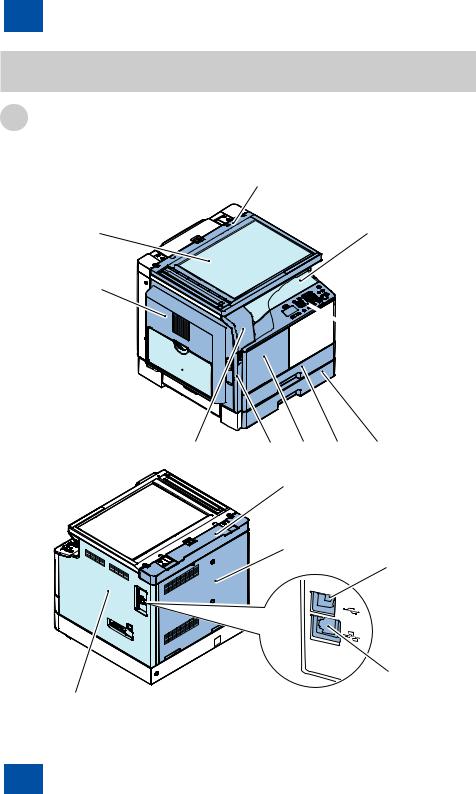
Name of Parts
External View
■■Network model
[9]
[10]
[11] 
[1]
[14]
[8]
[7]
 [6]
[6]
[2] [3] [4] [5]
F-1-4
[12]
[13]
[15]
[16]
F-1-5
1-8
[1]Reader front cover
[2]Left front cover
[3]Front cover
[4]Cassette 1
[5]Cassette 2
[6]Control panel assembly
[7]Delivery tray cover
[8]Reader upper unit
[9]Platen glass
[10]Left cover unit
[11]Multi-purpose pickup tray
[12]Reader rear cover
[13]Rear rover
[14]Right cover
[15]USB Port
[16]LAN Port
1-8
1Product Overview > Name of Parts > External View > Network model

1Product Overview > Name of Parts > External View > Local print model
■■Local print model
|
[7] |
[8] |
[6] |
[9] |
|
[5] |
[10]
[1] |
[2] |
[3] |
[4] |
F-1-6
[11]
[12]
[14]
[13]
F-1-7
1-9
[1]Reader front cover
[2]Left front cover
[3]Front cover
[4]Cassette 1
[5]Control panel assembly
[6]Delivery tray cover
[7]Reader upper unit
[8]Platen glass
[9]Left cover unit
[10]Multi-purpose pickup tray
[11]Reader rear cover
[12]Rear rover
[13]Right cover
[14]USB Port
1-9
1Product Overview > Name of Parts > External View > Local print model

1Product Overview > Name of Parts > Cross Sectional View
Cross Sectional View |
|
[1] |
|
[17] |
|
[16] |
|
[15] |
|
|
[2] |
[14] |
|
[13] |
[3] |
|
|
[12] |
[4] |
[11] |
|
[10] |
|
[9] |
|
[8] |
|
[7] |
|
[6] |
|
[5] |
|
F-1-8
1-10
[1] |
CIS unit |
|
[2] |
Laser scanner unit |
|
[3] |
Toner cartridge |
|
[4] |
Developing assembly |
|
[5] |
Cassette 2 pickup roller |
If equipped with the 1-cassette |
|
|
module. |
[6] |
Cassette 2 separation roller |
If equipped with the 1-cassette |
|
|
module. |
[7] |
Cassette 2 feed roller |
If equipped with the 1-cassette |
|
|
module. |
[8] |
Cassette 1 separation pad |
|
[9] |
Cassette 1 pickup roller |
|
[10] |
Multi-purpose tray separation pad |
|
[11] |
Multi-purpose tray pickup roller |
|
[12] |
Registration roller |
|
[13] |
Transfer roller |
|
[14] |
Drum unit |
|
[15] |
Fixing assembly |
|
[16] |
Duplex unit |
If equipped with the duplex unit. |
[17] |
Delivery roller |
|
1-10
1Product Overview > Name of Parts > Cross Sectional View

1Product Overview > Name of Parts > Control Panel > Power Switch
Control Panel
■■Power Switch
●●Types of power switch
Heater Switch
Energy Saver Key
Main Power Switch
F-1-9
This machine has the Main Power Switch, the Heater Switch and the Energy Saver Key.
[1] Main Power Switch
This switch is used to turn OFF / ON the power of host machine. [2] Heater Switch (option)
This switch is used to turn OFF / ON the power of the cassette heater. [3] Energy Saver Key
This switch is used to shift the machine to power-save mode or to restore it to normal mode.
1-11
●●Points to Note on Turning ON/OFF the Power Switch
•To turn off the power, turn off the Main power Switch. (Conventional shutdown sequence operation is not required.)
•After power-off (After the Main power Switch is turned off), do not reactivate the Main power Switch until a screen disappears.
•Do not turn off the power while download is processing.
1-11
1Product Overview > Name of Parts > Control Panel > Power Switch

1Product Overview > Name of Parts > Control Panel > Description of Control Panel
■■Description of Control Panel
●●Control Panel
Network model
[1] [2] |
[3] [4] |
[5] |
[6] |
[7] |
[8] [9] |
||||||||||||||
|
|
|
|
|
|
|
|
|
|
|
|
|
|
|
|
|
|
|
|
|
|
|
|
|
|
|
|
|
|
|
|
|
|
|
|
|
|
|
|
|
|
|
|
|
|
|
|
|
|
|
|
|
|
|
|
|
|
|
|
|
|
|
|
|
|
|
|
|
|
|
|
|
|
|
|
|
|
|
|
|
|
|
|
|
|
|
|
|
|
|
|
|
|
|
|
|
|
|
|
|
|
|
|
|
|
|
|
|
|
|
|
|
|
|
|
|
|
|
|
|
|
|
|
|
|
|
|
|
|
|
|
|
|
|
|
|
|
|
|
|
|
|
|
|
|
|
|
|
|
|
|
|
|
|
|
|
|
|
|
|
|
|
|
|
|
|
|
|
|
|
|
|
|
|
|
|
|
|
|
|
|
|
|
|
|
|
|
|
|
|
|
|
|
|
|
|
|
|
|
|
|
|
|
|
|
|
|
|
|
|
|
|
|
|
|
|
|
|
|
[18] |
[17] |
[16] |
[15][14] [13] |
[12] |
[11] |
[10] |
F-1-10
Local print model
[1] [2] |
|
[17] [3] [4] |
[5][7] |
[8] [9] |
||||||||||||||||
|
|
|
|
|
|
|
|
|
|
|
|
|
|
|
|
|
|
|
|
|
|
|
|
|
|
|
|
|
|
|
|
|
|
|
|
|
|
|
|
|
|
|
|
|
|
|
|
|
|
|
|
|
|
|
|
|
|
|
|
|
|
|
|
|
|
|
|
|
|
|
|
|
|
|
|
|
|
|
|
|
|
|
|
|
|
|
|
|
|
|
|
|
|
|
|
|
|
|
|
|
|
|
|
|
|
|
|
|
|
|
|
|
|
|
|
|
|
|
|
|
|
|
|
|
|
|
|
|
|
|
|
|
|
|
|
|
|
|
|
|
|
|
|
|
|
|
|
|
|
|
|
|
|
|
|
|
|
|
|
|
|
|
|
|
|
|
|
|
|
|
|
|
|
|
|
|
|
|
|
|
|
|
|
|
|
|
|
|
|
|
|
|
|
|
|
|
|
|
|
|
|
|
|
|
|
|
|
|
|
[13] [16][12][15] [11] |
[10] |
F-1-11
|
|
1-12 |
|
|
|
|
|
No. |
Name |
Function |
|
[1] |
Display |
During normal operation, displays messages and |
|
|
|
prompts. When adjusting the settings, displays your |
|
|
|
selections, text, and numbers. |
|
[2] |
[COPY/SCAN] key |
Press to switch the mode to copy or scan. |
|
[3] |
[Reset] key |
Press to reset the settings. |
|
[4] |
[▲] key |
Press to scroll up or to increase the value. |
|
|
|
|
|
|
[▼] key |
Press to scroll down or to decrease the value. |
|
|
[◄] key |
Press to return to the previous screen, or move the |
|
|
|
cursor to the left. |
|
|
[►] key |
Press to proceed to the next screen, or move the |
|
|
|
cursor to the right. |
|
|
[OK] key |
Press to confirm an action or setting. |
|
[5] |
[Status Monitor] Key |
Press to view the status of jobs or cancel jobs. Also |
|
|
|
check the status of the network or the machine. |
|
[6]*1 |
Numeric keys ([0]-[9]) |
Press to enter characters and numbers. |
|
|
[*] Key |
Press to switch the character entry mode. |
|
|
[#] Key |
Press to enter symbols. |
|
|
[C] Key |
Press to delete entered characters and numbers. |
|
[7] |
[Counter Check] Key |
Press this to display the total number of copies or |
|
|
|
prints (performed by the machine) on the display. |
|
[8] |
[Energy Saver] Key |
Press to manually set or cancel the Sleep mode. |
|
|
|
The Energy Saver indicator lights green while in the |
|
|
|
Sleep mode. |
|
[9][Settings/Registration] Key Press to specify or register various settings.
[10] |
[Stop] Key |
Press to cancel jobs. |
[11] |
[Start] Key |
Press to start a job. |
[12] |
[Error] Indicator |
Flashes when an error occurs. |
[13][Processing/Data] Indicator Flashes when the device is in operation, is on when
|
there is a job waiting to be processed. |
[14]*1 [Log In/Out] |
Press to log in/out when Department ID |
|
Management has been set. |
[15][Select Paper/Settings] Key Press to select a paper source, such as a drawer or
|
|
|
multi-purpose tray, and register paper size and type. |
|
[16] |
[Back] Key |
Press to return to the previous screen. |
|
[17] |
[ID Card Copy/Favorite |
Press to use the ID Card Copy and Favorite |
|
|
Settings] Key |
Settings. |
|
[18]*1 |
[2-Sided] Key |
Press to set 2-sided copies. |
*1: Network model only |
T-1-7 |
||
1-12
1Product Overview > Name of Parts > Control Panel > Description of Control Panel

2Technology■■Basic Configuration
■■Original Exposure System
■■Controller System
■■Laser Exposure System
■■Image Formation System
■■Fixing System
■■Pickup Feed System
2Technology
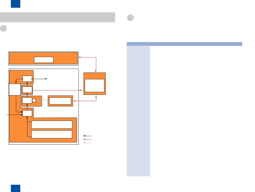
2Technology > Basic Configuration > Basic sequence > Basic Operation Sequence
Basic Configuration
Functional Configuration
The host machine is constructed by following functional system blocks; Document Exposure System, Controller System, Laser Exposure System, Image Formation System, Fixing System and Pickup/Feed System.
Original exposure system |
|
||
|
|
CIS unit |
|
|
Delivery |
|
Controller system |
|
|
Controller system |
|
|
|
|
|
Duplexing |
|
Fixing |
Engine control |
Fixing |
system |
System control |
|
feed |
|
Laser exposure system |
|
|
|
|
|
|
Transfer |
Laser scanner unit |
|
|
|
|
|
|
|
Image |
|
|
Pickup |
formation |
|
|
system |
|
|
Pickup/feed |
Cassette 1 |
|
|
|
|
||
system |
|
|
|
|
|
Cassette 2 |
Paper flow |
|
|
|
|
|
|
|
Signal flow |
|
|
|
Laser beam |
F-2-1
2-2
Basic sequence
■■Basic Operation Sequence
Basic Operation Sequence is controlled by engine controller. Each sequence, from main power switch ON until the main motor stops, is described as below. See timing chart for detail in the Appendix chapter.
|
Zone |
Purpose |
Remarks |
WAIT |
From main power switch ON |
Eliminates charging |
Detects the toner |
(wait) |
until the main motor stops |
on the surface of the |
cartridge while |
|
initial rotating. |
photosensitive drum |
it keeps heater |
|
|
and cleans the transfer |
temperature constant. |
|
|
roller and keeps heater |
|
|
|
temperature const. |
|
|
|
|
|
STBY |
From WAIT end or LSTR end |
Keeps the host machine |
|
(standby) |
until print indication command |
standby. |
|
|
is entered from the controller |
|
|
|
PCB (PCB1). |
|
|
|
|
|
|
INTR |
From print indication command |
Keeps photosensitive |
|
(initial rotation) |
is entered from the controller |
drum stable sensitivity |
|
|
PCB (PCB1) until the Pickup |
for print advance |
|
|
solenoid turns ON. |
preparations and cleans |
|
|
|
the transfer roller. |
|
|
|
|
|
From INTR end until top edge |
Forms image on |
|
|
(print) |
of the paper detect sensor |
the photosensitive |
|
|
detects end edge of the paper. |
drum, based on |
|
|
|
Video signal (/VDO1,/ |
|
|
|
VDO2,VDO1,VDO2) |
|
|
|
from the controller PCB |
|
|
|
(PCB1). It transfers toner |
|
|
|
image onto the paper. |
|
LSTR |
From PRINT end until the |
Eliminates the paper on |
Directly starts INTR |
(last rotation) |
main motor stops. |
the final job completely. |
after LSTR ends |
|
|
|
when print indication |
|
|
|
command is entered |
|
|
|
from the controller |
|
|
|
PCB (PCB1). |
|
|
|
|
|
|
|
T-2-1 |
|
|
|
2-2 |
2Technology > Basic Configuration > Basic sequence > Basic Operation Sequence
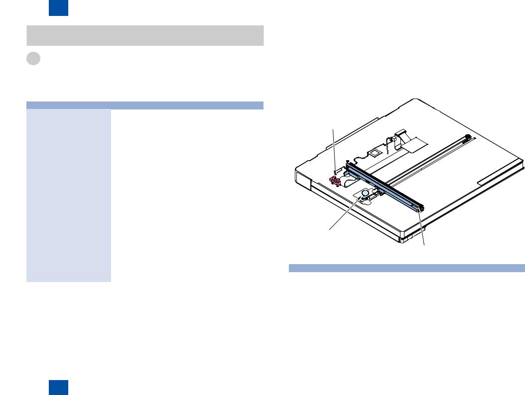
2Technology > Original Exposure System > Construction > Major Components
Original Exposure System
Construction
■■Specifications/controls/functions
The main specifications, controls and functions of the original exposure and feed system are described below.
Item |
Specification/Function |
|
Original exposure |
|
LED |
Original scan |
In book mode |
mobile CIS scanning |
|
In ADF mode |
fixed CIS scanning |
Read resolution |
|
B/W: 600 dpi (main scanning) x 600 dpi (sub scanning) |
|
|
Color SEND: 300 dpi (main scanning) x 600 dpi (sub scanning) |
Gradation |
|
256 gradation |
Carriage position detection |
Contact Sensor HP Sensor(SR402) |
|
Magnification |
|
25% to 400% |
|
|
|
|
Main scanning |
Image is processed on the controller PCB |
|
direction |
|
|
Sub scanning |
In book mode: Image is procesed by carriage speed and |
|
direction |
controller PCB *1 |
|
|
In ADF mode: Image is processed by paper delivery speed and |
|
|
controller PCB *1 |
Lens |
|
Rod lens array |
CMOS sensor |
|
Number of lines:1 |
|
|
Number of pixels: Total 7344 (incl. 7276 effective pixels) |
|
|
Maximum original scan width: 308mm |
CIS drive control |
|
Reader Motor(M301) |
Original size |
In book mode |
No |
detection |
|
|
|
In ADF mode |
Main scanning direction: photo interrupter |
|
|
|
|
|
Sub scanning direction: photo interrupter |
|
|
|
*1 Controls differ depending on magnifications. Refer to Magnification Change for detail. T-2-2
2-3
■■Major Components
Major components of the original exposure system is shows below.
Contact sensor HP sensor (SR402)
Reader motor
(M301)
|
|
CIS unit |
|
|
F-2-2 |
|
|
|
Item |
Code |
Specification/Function |
Reader Motor |
M301 |
Pulse Motor: carriage drive control |
|
|
|
Contact Sensor HP Sensor |
SR402 |
Photo interrupter: CIS home position detection |
|
|
|
CIS unit |
- |
LED Indirect exposure |
|
|
|
|
|
T-2-3 |
2-3
2Technology > Original Exposure System > Construction > Major Components
Loading...