


Contents |
|
|
|
Kinds of machines. . . . . . . . . . . . . . . . |
. . |
. . . . . |
1 |
Power table . . . . . . . . . . . . . . . . . . . . |
. . |
. . . . . |
5 |
Installing the motor. . . . . . . . . . . . . . . |
. . |
. . . . . |
6 |
Installing the machine head. . . . . . . . . . . |
. . |
. . . . |
7 |
Installing the motor pulley and belts. . . . . |
. . |
. . . . |
8 |
Motor pulley and belts . . . . . . . . . . . . . . |
. . |
. . . . |
9 |
Installing the spool holder base . . . . . . . . |
. . |
. . . . |
9 |
Installing the pedal . . . . . . . . . . . . . . . . |
. . |
. . . . |
10 |
Lubrication . . . . . . . . . . . . . . . . . . . . . |
. . |
. . . . |
10 |
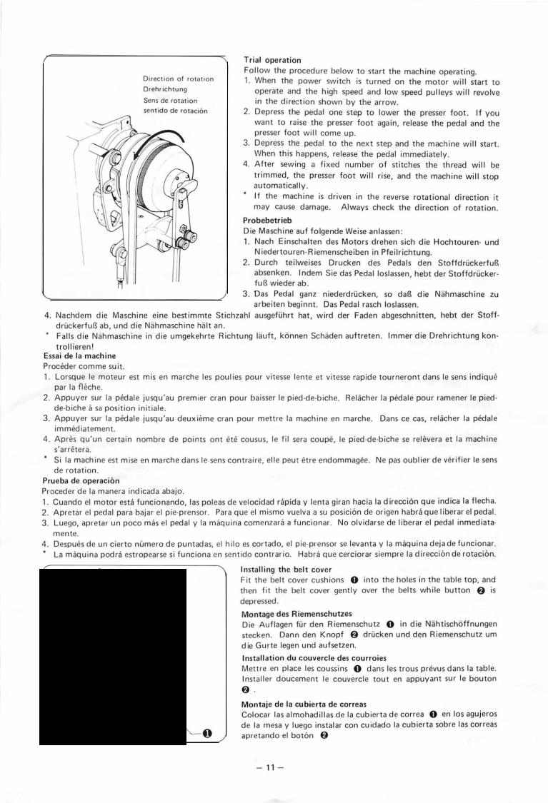
Trial operation . . . . . . . . . . . . . . . . . . . |
. . |
. . . . |
11 |
Installing the belt cover . . . . . . . . . . . . . |
. . |
. . . . |
11 |
Checking the basic operation of the machine |
. . . . . |
12 |
|
Basic operation of the power presser lifter . |
. . |
. . . . |
13 |
Basic operation of the tension discs. . . . . . |
. . |
. . . . |
14 |
Basic operation of the clutch. . . . . . . . . . |
. . |
. . . . |
15 |
Basic operation of the moving blade . . . . . |
. . |
. . . . |
15 |
Installing the needle. . . . . . . . . . . . . . . . |
. . |
. . . . |
17 |
Upper threading . . . . . . . . . . . . . . . . . . |
. . |
. . . . |
17 |
Selecting a needle and thread. . . . . . . . . . |
. . |
. . . . |
17 |
Bobbin winding. . . . . . . . . . . . . . . . . . . |
. . |
. . . . |
18 |
Inserting and removing the bobbin case |
|
|
|
and lower threading. . . . . . . . . . . . . . |
. . |
. . . . |
19 |
Lower thread tension . . . . . . . . . . . . . . . |
. . |
. . . . |
19 |
Upper thread tension. . . . . . . . . . . . . . . |
. . |
. . . . |
20 |
Thread take-up spring.............. |
; . . |
. . . . |
20 |
Using the stop lever. . . . . . . . . . . . . . . . |
. . |
. . . . |
21 |
Relpacing the fixed and moving blades . . . |
. . |
. . . . |
22 |
Needle bar height adjustment. . . . . . . . . . |
. . |
. . . . |
23 |
Needle bar adjustment . . . . . . . . . . . . . . |
. . |
. . . • |
23 |
Needle and rotary hook clearance adjustment. |
. . . . |
24 |
|
Brake spirng tension adjustment. . . . . . . . |
. . |
. . . . |
25 |
Needle and feed timing adjustment. . . . . . |
. . |
. . . . |
26 |
Thread take-up lever adjustment. . . . . . . . |
. . |
. . . . |
27 |
Tack length adjustment . . . . . . . . . . . . . |
. . |
. . . . |
28 |
Tack width adjustment. . . . . . . . . . . . . . |
. . |
. . . . |
28 |
Work clamp stroke adjustment. . . . . . . . . |
. . |
. . . . |
29 |
Moving blade position adjustment. . . . . . . |
. . |
. . . . |
30 |
Thread wiper adjustment . . . . . . . . . . . . |
. . |
. . . . |
31 |
Changing the feed cam and changer gear . . |
. . |
. . . . |
32 |
Changing the presser, feed palte, |
|
|
|
and needle hole plate. . . . . . . . . . . . . |
. . |
. . . . |
34 |
Trouble shooting. . . . . . . . . . . . . . . . . . |
. . |
. . . . |
35 |
Inhaltsverzeichnis |
|
|
|
|
|
|
Einteilung der Nahmaschinen. . . . . |
. . |
. . . |
. . |
. . • . |
2 |
|
Motorgestell . . . . . . . |
. . . . . . . . . |
. . |
. . . |
. . |
. . . . |
5 |
Aufstellung der Maschine . . . . . . . |
. . . |
. . . |
. |
. . • . |
6 |
|
Aufstellung des Maschinenoberteils. |
. . . |
. . . |
. |
. . . . |
7 |
|
Montage der Riemenscheibe und der Gurte |
. . . . . • |
8 |
||||
Motorriemenscheibe und Gurte . . . |
. . . |
. . . |
. |
. . . . |
9 |
|
Der Spulentrager. . . . |
. . . . • . • . . |
• . . |
. . . |
. |
. . . . |
9 |
Montage des pedals . . |
• . . . . . . . . |
. . . |
. . . |
. |
. . . . |
10 |
Schmierung . . . . . . . |
• . . . . . . . . |
. . . |
. . . |
. |
. . . . |
10 |
Probebetr ieb. . . . . . . |
. . . . . . . . . |
. . . |
. . |
~ . |
. . . . |
11 |
Montage des Riemenschutzes. . . . . |
. . . |
. . . |
. |
. . . . |
11 |
|
Oberprufung des Nahmaschinenbetriebs. |
. . . |
. |
• . . . |
12 |
||
Arbeitsweise des Stoffdruckerlufters |
. . . |
. . . |
. |
. . . . |
13 |
|
Arbeitsweise der oberen Spannscheiben. |
. . . |
. |
. . . . |
14 |
||
Arbeitsweise der Kupplung • . . . . . |
. . |
• . . . |
. |
. . . . |
15 |
|
Arbeitsweise des beweglichen Messers. . |
. . . |
. |
. . . . |
16 |
||
Nadelbefestigung. . . . . |
. . . . . . . . |
. . . |
. . . |
. |
. . . . |
17 |
Einfadeln des Oberfadens. . . . . . . . |
. . |
. . . |
. |
. . . . |
17 |
|
Nadel und Nahfaden . . |
. . . . . . . . . |
. . |
. . . |
. |
. . . . |
17 |
Der Spulvorgang . . . . . |
. . . . . . . . . |
. . |
. . . |
• • . . . |
18 |
|
Einlegen und Entnehmen der Spulenkapsel |
|
|
|
|||
und Einfadeln des Unterfadens. . . |
• • . . . |
. |
• • • . |
19 |
||
Unterfadenspannung . . |
. . . . . . . . . |
. . |
. . . |
. . |
. . . |
19 |
Oberfadenspannung . . . |
. . . . . . . . . |
. . |
. . . |
. . |
. . . |
20 |
Fadenabnahmefeder. . . |
. . . . . . . . . |
. . |
. . . |
. |
• . • . |
20 |
Der Stopphebel ....... |
: . • . . . . . |
. . |
• • • • . |
. . • |
21 |
|
Auswechseln der beweglichen |
|
|
|
|
|
|
und festen Messer . . |
. . . . . . . . . |
. |
• . . . |
. . |
. . . |
22 |
Einstellung der Nadelstangenhohe. • • • . |
. . . |
. . |
. . • |
23 |
||
Einstellung des Nadelstangenhubs........... |
|
|
|
'. . |
23 |
|
Einstellung des Abstands zwischen Nadel |
|
|
|
|||
und Schiffchennase . |
. . . . . . . . |
• . • . • . • . • . . |
24 |
|||
Einstellung der Bremsenfederspannung |
• . . . |
. . |
. . . |
25 |
||
Einstellung des Nadel und |
|
|
|
|
|
|
Transporteurgleichlaufs . . . . . . . |
• . |
. • . |
. . |
. . . |
26 |
|
Einstellung des Fadenabnahmehebels . . • . . |
. . |
. . . |
27 |
|||
Einstellung der Verriegelungslange . . |
• . • • . |
. . |
. . . |
28 |
||
Einstellung der Verriegelungsweite . • . • . . . |
. . |
. . . |
28 |
|||
Hubverstellung des StoffdruckerfuBes . . |
. . . |
. . |
. . • |
29 |
||
Positionierung des beweglichen Messers . |
. . . |
. . |
. . . |
30 |
||
Einstellung des Fadenwischers. . . . . |
. . |
. . . |
. . |
. • . |
31 |
|
Austauschen der Transportsteuerkurve |
|
|
|
|
||
und des Wechselrades. . . . . . . . . |
. . |
. . . |
. . |
. . . |
32 |
|
Austauschen des Stoffdruckers, der |
|
|
|
|
|
|
Transportplatte und des Stitchlocheinsatzes. |
. . . |
34 |
||||
Feh lersuche . . . . . . . . |
. . . . . . . . . |
. . |
. : . |
. . |
. • • |
37 |
From the library of: Superior Sewing Machine & Supply LLC

Table des matieres |
|
Differentes machines acoudre. . . . . . . . . . . . . . . |
3 |
Plateau de Ia machine. . . . . . . . . . . . . . . . . . . . . |
5 |
Installation du moteur . . . . . . . . . . . . . . . . . . . . |
6 |
Installation de Ia tete de Ia machine . . . . . . . . . . . |
7 |
Installation de Ia poulie du moteur |
|
et des courroies. . . . . . . . . . . . . . . . . . . . . . . |
8 |
Poulie du moteur et courroies . . . . . . . . . . . . . . . |
9 |
Socle du porte-bobine . . . . . . . . . . . . . . . . . . . . |
9 |
Installation de Ia pedale . . . . . . . . . . . . . . . . . . . |
10 |
Huilage .............................. |
10 |
Essai de Ia machine . . . . . . . . . . . . . . . . . . . . . . |
11 |
Installation du couvercle des courroies. . . . . . . . . . |
11 |
Verification des fonctions de base. . . . . . . . . . . . . |
12 |
Fonction de base du releveur du presseur. . . . . . . . |
13 |
Fonction de base des tendeurs de til . . . . . . . . . . . |
14 |
Fonction de base de l'embrayage ............. |
15 |
Fonction de base de Ia lame mobile. . . . . . . . . . . . |
16 |
Mise en place de l'aiguille . . . . . . . . . . . . . . . . . . |
17 |
Enfilage superieur . . . . . . . . . . . . . . . . . . . . . . . |
17 |
Aiguille et fil . . . . . . . . . . . . . . . . . . . . . . . . . . |
17 |
Bobinage de Ia canette . . . . . . . . . . . . . . . . . . . . |
18 |
Mise en place et depose du boitier de Ia |
|
canette et enfilage inferieur . . . . . . . . . . . . . . . |
19 |
Tension du fil de dessous . . . . . . . . . . . . . . . . . . |
19 |
Tension de fil de dessus . . . . . . . . . . . . . . . . . . . |
20 |
Ressort du tendeur . . . . . . . . . . . . . . . . . . . . . . |
20 |
Utilisation du levier d'arret . . . . . . . . . . . . . . . . . |
21 |
Changer les lames fixe et mobile. . . . . . . . . . . . . . |
22 |
Reglage de Ia hauteur de Ia barre aaiguille . . . . . . . |
23 |
Reglage de Ia course de Ia barre aaiguille . . . . . . . . |
23 |
Reglage de Ia distance aiguille-pointe |
|
du crochet de Ia canette . . . . . . . . . . . . . . . . . |
24 |
Reglage de Ia tension du ressort de frein. . . . . . . . . |
25 |
Reglage de Ia synchronisation |
|
aiguille-alimentation. . . . . . . . . . . . . . . . . . . . |
26 |
Reglage du guide-til . . . . . . . . . . . . . . . . . . . . . . |
27 |
Reglage de Ia longueur du point . . . . . . . . . . . . . . |
28 |
Reglage de Ia largeur du point . . . . . . . . . . . . . . . |
28 |
Reglage de Ia course du pied-de-biche . . . . . . . . . . |
29 |
Positionnement de Ia lame mobile. . . . . . . . . . . . . |
30 |
Reglage de l'ote-fil. . . . . . . . . . . . . . . . . . . . . . . |
31 |
Changement de Ia came d'entrainement |
|
et de l'engrenage du changeur . . . . . . . . . . . . . |
32 |
Changement du pied presseur, de Ia plaque |
|
d'entrarnement et de Ia plaque d'aiguille . . . . . . |
34 |
Guide de depannage. . . . . . . . . . . . . . . . . . . . . . |
39 |
lndice de contenido |
|
Diferentes tipos de Maquinas . . . . . . . . . . . . . . . |
4 |
Mesa de Ia maquina . . . . . . . . . . . . . . . . . . . . . . |
5 |
Montaje del motor. . . . . . . . . . . . . . . . . . . . . . . |
6 |
Montaje de Ia cabeza de Ia maquina. . . . . . . . . . . . |
7 |
Montaje de Ia polea del motor y de las correas. . . . . |
8 |
La polea del motor y las correas. . . . . . . . . . . . . . |
9 |
Base de porta-cones . . . . . . . . . . . . . . . . . . . . . . |
9 |
Montaje del pedal . . . . . . . . . . . . . . . . . . . . . . . |
10 |
Lubricaci6n . . . . . . . . . . . . . . . . . . . . . . . . . . . |
10 |
Prueba de operacion. . . . . . . . . . . . . . . . . . . . . . |
11 |
Montaje de Ia cubierta de correas . . . . . . . . . . . . . |
11 |
Comprobaci6n de Ia operacion basica |
|
de Ia maquina . . . . . . . . . . . . . . . . . . . . . . . . |
12 |
Operacion basica del levantador del |
|
prensor de energ ia . . . . . . . . . . . . . . . . . . . . . |
13 |
Operacion basica de los discos |
|
de tension superior . . . . . . . . . . . . . . . . . . . . |
14 |
Qperacion fundamental del embrague . . . . . . . . . . |
15 |
Operacion fundamental de Ia cuchilla movible. . . . . |
16 |
Montaje de Ia aguja . . . . . . . . . . . . . . . . . . . . . . |
17 |
Hila superior . . . . . . . . . . . . . . . . . . . . . . . . . . |
17 |
La aguja y el hila. . . . . . . . . . . . . . . . . . . . . . . . |
17 |
Como llenar Ia canilia. . . . . . . . . . . . . . . . . . . . . |
18 |
Para insertar y sacar Ia caja de Ia |
|
canilla e hila inferior . . . . . . . . . . . . . . . . . . . |
19 |
Tension del hila inferior . . . . . . . . . . . . . . . . . . . |
19 |
Tension del hila superior. . . . . . . . . . . . . . . . . . . |
20 |
Muelle del tira hila. . . . . . . . . . . . . . . . . . . . . . . |
20 |
Como usar Ia palanca de parada . . . . . . . . . . . . . . |
21 |
Reemplazar las cuchillas movibles y fijadas. . . . . . . |
22 |
Ajuste de Ia altura de Ia barra de Ia aguja . . . . . . . . |
23 |
Ajuste del curse de Ia barra de Ia aguja. . . . . . . . . . |
23 |
Ajuste del espacio de Ia aguja y del gancho |
|
de Ia lanzadera . . . . . . . . . . . . . . . . . . . . . . . |
24 |
Ajuste de Ia tension del frena de muelle. . . . . . . . . |
25 |
Ajuste de Ia sincronizaci6n de alimentaci6n |
|
y de Ia aguja. . . . . . . . . . . . . . . . . . . . . . . . . |
26 |
~juste de Ia palanca del tira hila. . . . . . . . . . . . . . |
27 |
Ajuste de Ia largura de puntada . . . . . . . . . . . . . . |
28 |
Ajuste de anchura de puntada . . . . . . . . . . . . . . . |
28 |
Ajuste del curse del pie prensor . . . . . . . . . . . . . . |
29 |
Ajuste de posicion de Ia cuchilla movible . . . . . . . . |
30 |
Ajuste del libra-hila. . . . . . . . . . . . . . . . . . . . . . |
31 |
Manera de cambiar el excentrico de |
|
alimentaci6n y el engranaje de cambia. . . . . . . . |
32 |
Cambia del prernatelas, placa de alimentaci6n |
|
y de Ia placa del agujero de Ia aguja. . . . . . . . . . . |
34 |
Localizaci6n de fallas. . . . . . . . . . . . . . . . . . . . . |
41 |
From the library of: Superior Sewing Machine & Supply LLC

Kinds of sewing machine
The following are examples of possible patterns with the LK3-B484.
Stitching |
|
|
|
|
|
|
|
|
|
|
|
|
|
|
|
|
|
|
|
|
|
|
|
|
|
|
|
|
|
|
|
|
|
|
|
|
|
|
|
|
|
|
|
|
|
|
|
patterns |
|
|
|
|
|
|
|
|
|
|
|
|
|
|
|
|
|
|
|
|
|
|
|
|
|
|
|
|
|
|
|
|
|
|
|
Front rubber attaching |
|
|
|
|
|
|
|
|
|
|
|
Uses |
|
|
|
|
Tongue tacking stitch |
Heel attaching stitch |
|||||||||
|
|
|
stitch |
|
|||||||||||
|
|
|
|
|
|
|
|
|
|
|
|
|
|
||
|
|
|
|
|
|
|
|
|
|
|
|
|
|||
Number of stitches |
98 |
70/2 |
|
|
|
84/2 |
|
||||||||
|
|
|
|
|
|
|
|
|
|
|
|
|
|
|
|
Stitching |
|
|
|
|
|
|
|
|
|
|
|
|
|
|
|
patterns |
|
|
|
|
|
|
|
|
|
|
|
|
|
|
|
|
|
|
|
|
|
|
|
|
|
|
|
|
|
|
|
Uses |
|
|
Curtain darts stitch |
|
Fashion belt attaching |
Label attaching stitch |
|||||||||
|
|
|
stitch |
||||||||||||
|
|
|
|
|
|
|
|
|
|
|
|
||||
|
|
|
|
|
|
|
|
|
|
|
|
|
|
||
Number of stitches |
98 |
84 |
|
|
|
49 |
|
|
|||||||
|
|
|
|
|
|
|
|
|
|
|
|
|
|
|
|
Stitching |
|
|
|
|
|
|
|
|
|
|
|
|
|
|
|
|
|
|
|
|
|
|
|
|
|
|
|
|
|
|
|
|
|
|
|
|
|
|
|
|
|
|
|
|
|
|
|
patterns |
|
|
|
|
|
|
|
|
|
|
|
|
|
|
|
|
|
|
|
|
|
|
|
|
|
|
|
||||
|
|
|
|
|
|
|
|
|
|
|
|
|
|
|
|
|
|
|
|
|
|
|
|
|
|
|
|
||||
Uses |
|
Safety belt attaching stitch |
|
Hand attaching stitch |
|
Belt hem stitch |
|||||||||
|
|
|
|
|
|
|
|
|
|||||||
Number of stitches |
140 |
77 |
|
|
|
98/2 |
|
||||||||
|
|
|
|
|
|
|
|
|
|
|
|
|
|
|
|
Stitching |
|
|
|
|
|
|
|
|
|
|
|
|
|
|
|
|
|
|
|
|
|
|
|
|
|
|
|
|
|
|
|
patterns |
|
|
|
|
|
|
|
|
|
|
|
|
|
|
|
|
|
|
|
|
|
|
|
|
|
|
|||||
|
|
|
|
|
|
|
|
|
|||||||
Uses |
|
|
|
Hart-shaped tacking |
|
Label attaching stitch |
Label attaching stitch |
||||||||
|
|
|
|
|
|
|
|
|
|||||||
Number of stitches |
70 |
84 |
|
|
|
126 |
|
|
|||||||
|
|
|
|
|
|
|
|
|
|
|
|
|
|
|
|
|
|
|
|
|
|
-1- |
|
|
|
|
|
|
|
|
|
From the library of: Superior Sewing Machine & Supply LLC

Nihmaschinentypen
Untenstehend sind Stitchmuster abgebildet, welche mit der LK3-B484 ausgefuhrt werden konnen.
Stichmuster
Anwendung |
Stich zum Befestigen von |
Stich fUr Zungenmuster |
Stich fur Fersen |
|
Gummibandern |
||||
|
|
|
||
|
|
|
|
|
Stichzahl |
98 |
70/2 |
84/2 |
Stichmuster
Anwendung |
Stich fur Vorhangabnaher |
Stich fur Modegi.irtel |
Stich fur Etti kets |
|
|
|
|
Stichzahl |
98 |
84 |
49 |
Stichmuster
Anwendung |
Stich fur Sicherheitsgurte |
Stich fur Verstarkungen |
Stich fur Gurtelsaum |
|
|
|
|
|
|
Stichzahl |
140 |
|
77 |
98/2 |
|
|
|
|
|
Stichmuster |
|
|
.... |
|
|
|
|
|
|
|
|
|
|
|
|
|
|
|
|
Anwendung |
Stich fur Herzmuster |
Stich fur Ettikets |
Stich fur Etti kets |
|
|
|
|
Stichzahl |
70 |
84 |
126 |
- 2 -
From the library of: Superior Sewing Machine & Supply LLC

Types de machines
Voici quelques exemples de motifs realisables avec Ia LKJ-8484.
Points decoratifs |
|
|
|
|
|
|
|
|
|
|
|
|
|
|
|
|
|
|
|
|
|
|
|
|
|
|
|
|
|
|
|
|
|
|
|
|
|
|
|
|
|
|
|
|
|
|
|
|
|
|
|
|
|
|
|
|
|
|
|
|
|
|
|
|
|
|
|
|
|
|
|
|
|
|
|
|
|
|
|
|
|
|
|
|
UtiIisat ions pri ncipales |
|
|
Point d'attache pour |
|
|
Point de batissage de patte |
Point d'attache de talon |
|||||||||
|
|
|
caoutchouc avant |
|
|
|||||||||||
|
|
|
|
|
|
|
|
|
|
|
|
|
||||
Nombre de points |
|
|
98 |
70/2 |
|
84/2 |
|
|
||||||||
|
|
|
|
|
|
|
|
|
|
|
|
|
|
|
|
|
Points decoratifs |
l |
........ |
,....J.......... |
|
|
|
|
|
|
|
|
|
||||
|
|
|
|
|
|
|
|
|
|
|
|
|
|
|
|
|
Utilisations principales |
|
|
Point pour pince de rideau |
|
|
Point d' attache pour |
Point d'attache pour |
|||||||||
|
|
|
|
ceinture de mode |
|
etiquette |
||||||||||
|
|
|
|
|
|
|
|
|
|
|
||||||
Nombre de points |
|
|
98 |
84 |
|
49 |
|
|
||||||||
|
|
|
|
|
|
|
|
|
|
|
|
|
|
|
|
|
Points de decoratifs |
|
|
|
|
|
|
|
|
|
|
|
|
|
|
|
|
|
|
|
|
|
|
|
|
|
|
|
|
|
|
|
|
|
|
|
|
|
|
|
|
|
|
|
|
|
|
|
|
|
|
|
|
|
|
|
|
|
|
|
|
|
|
|
|
|
|
|
|
|
|
|
|
|
|
|
|
|
|
|
|
|
|
||
|
|
|
|
|
|
|
|
|
|
|
|
|
|
|
|
|
|
|
|
|
|
|
|
|
|
|
|
|
|
|
|
|
|
|
|
|
|
|
|
|
|
|
|
|
|
|
|
|
||
Utilisations principales |
|
|
Point d'attache pour |
|
|
Point "main" |
Point d' ourlet pour ceinture |
|||||||||
|
|
|
ceinture de securite |
|
|
|||||||||||
|
|
|
|
|
|
|
|
|
|
|
|
|
||||
Nombre de points |
|
|
140 |
77 |
|
98/2 |
|
|
||||||||
|
|
|
|
|
|
|
|
|
|
|
|
|
|
|
|
|
|
|
|
|
|
|
|
|
_._ |
|
|
|
|
|
|
||
Points decoratifs |
|
|
|
|
|
|
|
|
|
|
|
|
|
|
|
|
|
|
|
|
|
|
|
|
|
|
|
||||||
|
|
|
|
|
|
|
|
|
|
|
||||||
Uti Iisations principales |
|
|
Point d'arret en forme |
|
|
Point d'attache pour |
Point d'attache pour |
|||||||||
|
|
|
|
de coeur |
|
|
etiquette |
|
etiquette |
|||||||
Nombre de points |
|
|
70 |
84 |
|
126 |
|
|
||||||||
|
|
|
|
|
|
|
|
|
|
|
|
|
|
|
|
|
|
|
|
|
|
|
|
|
- 3 - |
|
|
|
|
|
|
||
From the library of: Superior Sewing Machine & Supply LLC

Diferentes tipos de Maquinas
Los ejemplos que siguen ilustran dibujos realizables con Ia LK3-B484.
Puntada decorativa
Utilidades principales |
Puntada para unir suelas |
Puntada rematadora de |
Puntada para unir el tac6n |
|
de goma |
Ia lengueta |
|||
|
|
|||
|
|
|
|
|
Numero de puntadas |
98 |
70/2 |
84/2 |
Puntada decorativa i.."""""'tllll!llh'J..... "''
Util idades principales |
Puntada para pinzas de |
Puntada decorativa de |
Pu ntada para coser etiquetas |
|
cortina |
cintur6n |
|||
|
|
|||
|
|
|
|
|
Numero de puntadas |
98 |
84 |
49 |
Puntada decorativa
UtiIidades principal es |
Puntada para unir |
Puntada para unir asas |
Puntada para coser el |
|
cinturones de seguridad |
dobladillo de Ia cintura |
|||
|
|
|||
|
|
|
|
|
Numero de puntadas |
140 |
27 |
98/2 |
_,
Puntada decorativa
Utilidades principales |
Puntada para de coraz6n |
~untada para coser etiquetas |
Puntada para coser etiquetas |
|
|
|
|
Numero de puntadas |
70 |
84 |
126 |
- 4 -
From the library of: Superior Sewing Machine & Supply LLC

Power table
Use one of the following special 8430 type power tables.
Motorgestell
Verwenden Sie eins der unten aufgelisteten 8430-Motor- gestelle.
|
|
|
|
|
|
|
|
|
|
|
|
Model code |
|
|
|
|
|
|
|
|
|
|
Modeii-Code |
|
|
|
|||||
|
|
|
|
|
|
|
|
|
|
|
|
|
|
|
|
|
|
|
|
|
|
|
|
|
|||||||
|
Table with leg assembly |
|
|
|
|
|
128-201-430-49 |
|
|
|
|
|
|
|
Nahtisch |
|
|
|
|
128-201-430--49 |
|
|
|||||||||
|
|
|
|
|
|
|
|
|
|
|
|
|
|
|
|
|
|
|
|
|
|
|
|
|
|
|
|
|
|
|
|
|
|
|
|
|
|
Single |
|
|
184-256--001 |
|
|
|
|
|
|
|
|
|
einphasig |
|
184-256--001 |
|
|
|
|||||||
|
Motor and switch |
|
phase |
|
|
|
|
|
|
|
|
|
Motorund |
|
|
|
|
|
|||||||||||||
|
|
|
|
|
|
|
|
|
|
|
|
|
|
|
|
|
|
|
|
|
|
|
|
||||||||
|
assembly |
|
|
Thread |
|
184-281-001 |
|
|
|
|
|
|
|
Scha ltgestell |
|
dreiphasig |
|
184-281-001 |
|
|
|
||||||||||
|
|
|
|
|
|
phase |
|
|
|
|
|
|
|
|
|
|
|
|
|
|
|
||||||||||
|
|
|
|
|
|
|
|
|
|
|
|
|
|
|
|
|
|
|
|
|
|
|
|
|
|
|
|
|
|||
|
|
|
|
|
|
|
|
|
|
|
|
|
|
|
|
|
|
|
|
|
* Wenn Sie einen Motor separat kaufen, wahlen Sie eine |
||||||||||
|
* If purchasing a motor |
separately, select either of the |
|
||||||||||||||||||||||||||||
|
|
|
following types. |
|
|
|
|
|
|
|
|
|
|
|
|
|
|
|
der untenstehenden Motortypen: |
|
|
|
|||||||||
|
|
|
|
|
|
|
|
|
|
|
|
|
|
|
|
|
|
|
|
|
|
|
|
|
|
||||||
|
|
Single phase |
1OOV |
|
|
4 pole 250W motor |
|
|
|
|
|
Einphasig, |
1OOV |
|
|
4 poliger 250W-Motor |
|
||||||||||||||
|
|
|
|
|
|
|
|
|
|
|
|
|
|
|
|
|
|
|
|
|
|
|
|
|
|
|
|
||||
|
|
Three phase |
200V |
|
|
4 pole 250W motor |
|
|
|
|
|
|
|
|
|
|
|
|
|
|
|
|
|||||||||
|
|
|
|
|
|
|
|
Dreiphasig, |
200V |
|
|
4 poUger 250W-Motor |
|
||||||||||||||||||
|
|
|
|
|
|
|
|
|
|
|
|
|
|
|
|
|
|
|
|
|
|
|
|
||||||||
|
|
|
|
|
|
|
|
|
|
|
|
|
|
|
|
|
|
|
|
|
|
|
|
|
|
|
|
|
|||
|
|
|
|
|
|
|
|
|
|
|
|
|
|
|
|
|
|
|
|
|
|
|
|
|
|
|
|
|
|||
|
Plateau de Ia machine |
|
|
|
|
|
|
|
|
|
|
|
|
|
|
|
Mesa de Ia maquina |
|
|
|
|
|
|
|
|
||||||
|
Util iser une des tables de |
type 8430 speciales suivantes. |
|
UtiIizar una de las siguientes |
mesas especiales de tipo |
||||||||||||||||||||||||||
|
|
|
|
|
|
|
|
|
|
|
|
|
|
|
|
|
|
|
|
8430. |
|
|
|
|
|
|
|
|
|
|
|
|
|
|
|
|
|
|
|
|
|
|
|
|
|
-------- |
|
C6digo del modelo |
|
|
|||||||||||||
|
|
Ensemble table avec pieds |
|
|
|
128-201-430-49 |
|
|
|
|
|
|
|
|
|
||||||||||||||||
|
|
|
|
|
|
|
|
|
|
|
|
Code de modele |
|
|
|
|
|
|
|
|
|
|
|
||||||||
|
|
|
|
|
|
|
|
|
|
|
|
|
|
|
|
|
|
|
|
|
Mesa de conjunto con pie |
|
|
|
128-201-430-49 |
|
|
||||
|
|
|
|
|
|
|
|
|
|
|
|
|
|
|
|
|
|
|
|
|
|
|
|||||||||
|
|
Element moteur et |
|
Monophase |
184-256-001 |
|
|
|
|
|
|
|
Conjunto de motor |
Fase (mica |
|
184-256-001 |
|
|
|||||||||||||
|
|
|
|
|
|
|
|
|
|
|
|
|
|
|
|
|
|
|
|
|
|
|
|
|
|
||||||
|
|
commutateur |
|
Triphase |
|
184-281-001 |
|
|
|
|
|
|
|
e interrupter |
Fase triple |
|
184-281-001 |
|
|
||||||||||||
|
|
|
|
|
|
|
|
|
|
|
|
|
|
|
|
|
|
|
|
||||||||||||
|
|
|
|
|
|
|
|
|
|
|
|
||||||||||||||||||||
|
* Si le moteur est achete separement, choisir l'un des |
|
* Si se compra el motor separadamente habra que |
||||||||||||||||||||||||||||
|
|
|
types suivants. |
|
|
|
|
|
|
|
|
|
|
|
|
|
|
|
escoger uno de los siguientes tipos. |
|
|
|
|||||||||
|
|
|
|
|
|
|
|
|
|
|
|
|
|
|
|
|
|
|
|
|
|
|
|
|
|
|
|
||||
|
|
Monophase |
1OOV |
|
|
|
|
Quadripole |
250W |
|
|
|
|
Fase (mica |
1OOV |
|
|
|
|
cuatripole |
250W |
|
|
||||||||
|
|
|
|
|
|
|
|
|
|
|
|
|
|
|
|
|
|
|
|
|
|
|
|
|
|
|
|
||||
|
|
Triphase |
200V |
|
|
|
|
Quadripole |
250W |
|
|
|
|
Fase triple |
200V |
|
|
|
|
cuatripole |
250W |
|
|
||||||||
|
|
|
|
|
|
|
|
|
|
|
|
|
|
|
|
|
|
|
|
|
|
|
|
|
|
|
|
||||
|
|
|
|
|
|
|
|
|
|
|
|
|
|
|
|
|
|
|
|
|
* If using a commercially available table, place the |
||||||||||
|
|
|
|
|
|
|
|
|
|
|
|
|
|
|
|
|
|
|
|
|
|||||||||||
|
|
|
|
|
|
|
|
|
|
|
|
|
|
|
|
|
|
|
|
|
|||||||||||
|
|
|
|
|
|
|
|
|
|
|
|
|
|
|
|
|
|
|
|
|
included |
table sheet |
on the table and make the |
||||||||
|
|
|
|
|
|
|
|
|
|
|
|
|
|
|
|
|
|
|
|
|
appropriate holes. |
|
|
|
|
|
|
|
|||
|
|
|
|
|
|
|
|
|
|
|
|
|
|
|
|
|
|
|
|
|
* Falls ein handelsublicher Nahtisch verwendet wird, |
||||||||||
|
|
|
|
|
|
|
|
|
|
|
|
|
|
|
|
|
|
|
|
|
legen Sie die mitgelieferte Vorlage auf den Tisch, und |
||||||||||
|
|
|
|
|
|
|
|
|
|
|
|
|
|
|
|
|
|
|
|
|
bohren Sie die entsprechenden Locher. |
|
|
|
|||||||
|
|
|
|
|
|
|
|
|
|
|
|
|
|
|
|
|
|
|
|
|
* Si une table quelconque est utilisee comme support |
||||||||||
|
|
|
|
|
|
|
|
|
|
|
|
|
|
|
|
|
|
|
|
|
pour Ia machine, placer sur celle-ci le tapis fourni avec |
||||||||||
|
|
|
|
|
|
|
|
|
|
|
|
|
|
|
|
|
|
|
|
|
Ia machine et percer les trous necessaires. |
|
|
|
|||||||
|
|
|
|
|
|
|
|
|
|
|
|
|
|
|
|
|
|
|
|
|
* Si se usa una mesa adquisible en el mercado, habra |
||||||||||
|
|
|
|
|
|
|
|
|
|
|
|
|
|
|
|
|
|
|
|
|
que colocar Ia lamina incluida en Ia mesa y proceder a |
||||||||||
|
|
|
|
|
|
|
|
|
|
|
|
|
|
|
|
|
|
|
|
|
hacer los agujeros en los lugares apropiados. |
||||||||||
|
|
|
|
|
|
|
|
|
|
|
|
|
|
|
|
|
|
|
|
|
|
|
|
|
|
|
|
|
|
|
|
|
|
|
|
|
|
|
|
|
|
|
|
|
|
|
|
|
|
|
|
|
|
|
|
|
|
|
|
|
|
|
|
- 5 -
From the library of: Superior Sewing Machine & Supply LLC

Center
Motormittellinie
Centre de moteur
Centro del motor
t.n
......
......
N
<0
Installing the motor
Fit the cushions 0 and cushion collars f) supplied into the four places in the motor base 8 , and install the motor as shown in the above diagram.
*If you have purchased a motor separately, it may not be installed on the motor base. If this is the case, purchase a separate motor base without holes and then make the holes to the measurements shown in the above diagram.
Aufstellung der Maschine
Die mitgelieferten Auflagen 0 und f) in die vier Locher der Motorgrundplatte 8 pressen und den Motor, wie aus der obigen Abbildung ersichtlich, aufsetzen.
*Falls Sie den Motor separat gekauft haben, ist er vielleicht nicht auf einer Grundplatte montiert. Kaufen Sie in einem solchen Faile eine Motorgrundplatte ohne Locher. Bohren Sie Locher, wie aus der obigen Abbildung ersichtlich.
Installation du moteur
Mettre en place les coussins 0 et les entretoises de coussin f) inclus aux quatre endroits dans le socle du moteur
8 , et installer le moteur. Voir figure ci-dessus.
*Si le moteur a ete achete separement, son installation sur le socle du moteur peut etre impossible. Le cas echeant, acheter un socle de moteur sans trous et percer des trous d'apn!s les mesures montrees sur Ia figure ci-dessus.
Montaje del motor |
0 y los aros f) ae las almohadillas que se encuentran en los cuatro lugares de Ia base del |
Colocar las almohadillas |
|
motor 8 y montarlo. |
Ver Ia ilustraci6n arriba. |
*Si el motor ha sido comprado separadamente, tal vez no pueda ser montado en Ia base de Ia mesa. En ese caso, habra que comprar una base separada sin agujeros para el motor y hacerlos de acuerdo con Ia ilustraci6n.
- 6 -
From the library of: Superior Sewing Machine & Supply LLC
Installing the machine head
1.Install the oiler supporter 8 to the bottom of the oil pan 0 with two screws 8. Install the oiler 0 to the oiler supporter 8.
2.Attach the oil pan 0 to the table with the four fait-head screws 0.
3.Attach the bed cushions 0 in the four corners of the oil pan 0, and set the bed gently on top of the oil pan.
4.Tilt the machine back towards the opposite side, loosen screw 8, fit the head support pin 0 into the oblong hole in the head support lever 0, and then tighten screw 8.
5.To return the machine to its original position, pull the head support lever 0 towards you and gently lower the machine into position.
Aufstellung des Maschinenoberteils
1.Den Olerhalter 8 mit zwei Schrauben 8 an dem Olwannenboden 0 so befestigen daB der Oler 8 auf dem 01- wannenboden liegt.
2.Mit den vier Senkschrauben Ci) die Olfangschale 0 am Tisch befestigen.
3. Die vier Maschinenbett auflagen 0 in den Ecken der Olfangschale 0 auflegen, und das Maschinenbett vorsichtig auf die Olfangschale aufsetzen.
4.Die Maschine in die andere Richtung zuruckkippen, die Schraube 8 losen, den Maschinenkopf-Fuhrungszapfen 0 durch das Uingsloch im Fuhrungshebel C!) stecken und die Schraube 8 festziehen.
5.Urn die Maschine zuruckzustellen, den Fuhrungshebel 0 zu sich ziehen und die Maschine Iangsam absenken.
Installation de Ia t@te de Ia machine |
|
|
1. |
lnstallez le support de graisseur 8 au fond du carter d'huile 0 avec deux vis de serrage et mettez Ia graisseur 0. |
|
2. |
Fixer le carter al'huile 0 aIa table aI'aide des quatre vis atete plate 0. |
|
3. |
Fixer les coussins 0 aux quatre coins du carter al'huile |
0, et poser doucement Ia table sur le carter al'huile. |
4. |
Incliner Ia machine vers le cote coppose, desserrer Ia |
vis 8, loger Ia goupilte-support de Ia tete 0 dans le trou |
|
allonge prevu dans te levier-support de Ia tete C!), et serrer Ia vis f). |
|
5. |
Pour ramener Ia machine aIa position originale, tirer le levier-support de Ia tete 0 vers soi et baisser doucement Ia |
|
|
machine. |
|
Montaje de Ia cabeza de Ia maquina |
|
|
1. |
Ponga el soporte de Ia aceitera de plastico 8 a Ia charola de aceite 8 apretando los dos torniltos 8 y fije Ia aceitera |
|
2. |
••Fijar Ia charola del aceite 0 en Ia mesa con los cuatro torniltos de cabeza lisa 8. |
|
3.Fijar las almohadillas 0 en los cuatro cantos de Ia charola del aceite e. y poner Ia misma con cuidado sobre Ia charola del aceite.
4.lnclinar Ia maquina hacia al lado opuesto, aflojar los tornillos 8, ajustar el perno de soporte de Ia cabeza 0 a los
agujeros en Ia palanca de soporte de Ia cabeza 0 y luego apretar los torniltos f).
5. Para retornar Ia maquina a su posicion de origen, habra que tirar de Ia palanca de soporte de Ia cabeza 0 hacia si y bajar Ia maquina con cuidado.
- 7 -
From the library of: Superior Sewing Machine & Supply LLC

Installing the motor pulley and belts
1.Push the motor pulley completely onto the motor shaft, and then insert one of the two motor pulley set screws through the opening on the motor pulley and screw it down until it contacts the flat surface of the shaft.
2. |
Pass the low speed belt® around the low speed pulley 0 and the narrower part of the motor pulley fJ. |
|
3. |
Pass the high speed belt@ around the high speed pulley 0 and the wider part of the motor pulley 8. |
|
4. |
To adjust the tension of the high speed belt @, loosen nut 0 and move the motor base 0 up or down so that |
|
|
the high speed belt @will bend about 10 mm when depressed around the center with your finger. |
|
5. |
After adjusting the high speed belt @, adjust the tension of the low speed belt ® |
as follows. Loosen bolt 8, |
|
and move the tension pulley G to the left or right so that the low speed belt ®will |
bend approximately 10 mm. |
*If the belt tension is stronger or weaker than necessary, the machine may not operate properly. Always check the tension of the belts.
Montage der Riemenscheibe und der Gurte
1.Die Riemenscheibe ganz auf die Motorwelle schieben. Dann eine der beiden Stellschrauben durch die Scheibenoffnung stecken und so weit hineinschrauben, daB sie die glatte Wellenoberflache beruhrt.
2.Den Niedertourengurt ® um die Niedertouren-Riemenscheibe 0 und den durchmesserschmalen Motorrie-
|
menscheibenteil fJ legen. |
|
3. |
Den Hochtourengurt @ um die Hochtouren-Riemenscheibe 0 und den durchmesserbreiten Motorriemenschei- |
|
|
benteil e legen. |
|
4. |
Die Spannung des Hochtourengurts @ folgendermaBen einstellen: Die Mutter 0 |
losen und die Motorgrundplatte |
|
0 so weit nach oben oder unten verschieben, daB sich der Hochtourengurt @ |
in der Mitte ungefahr 10 mm mit |
|
dem Finger durchdrucken laBt. |
|
5. |
Nach erfolgter Einstellung des Hochtourengurts @ ist die Spannung des Niedertourengurts ® einzustellen: Die |
|
Schraube 8 losen und die Spannrolle G so weit nach rechts oder links verschieben, daB sich der Niedertourensurt @ ungefahr 10 mm durchdrucken laBt.
*Falls die Riemenspannung zu groB oder gering ist, arbeitet die Maschine nicht richtig. Oberprufen Sie regelmaBig die Riemenspannungen.
Installation de Ia poulie du moteur et des courroies
1.Pousser completement Ia poulie du moteur sur l'arbredu moteur, et introduire une des deux vis d'arretde poulie du moteur par !'orificesur Ia poulie du moteur et Ia visser jusqu'ace qu'elleentre en contacte avec Ia surface plate de l'arbre.
2.Passer Ia courroie pour vitesse lente @ autour de Ia poulie appropriee 0 et autour de Ia poulie du moteur a petit
|
diametre fJ. |
autour de Ia poulie appropriee 0 |
et autour de Ia poulie du moteur a |
|
3. |
Passer Ia courroie pour vitesse rapide @ |
|||
|
grand diametre e. |
, desserrer l'ecrou0 et baisser ou |
lever le socle du moteur 0 de sorte |
|
4. |
Pour regler Ia tension de Ia courroie @ |
|||
|
que Ia fh!che de Ia courroie pour vitesse |
rapide |
@ soit de 10 mm lorsqu'onappuie du doigt a mi-chemin de Ia |
|
|
courroie. |
|
@ , n!gler: Ia tension de I'autre courroie ® comme suit. Desserrer |
|
5. |
Apres avoir regie Ia courroie pour vitesse rapide |
|||
|
le boulon 8 , et deplacer Ia poulie de tension G vers Ia droite ou vers Ia gauche de sorte que Ia fleche soit de |
|||
10 mm environ.
*Si Ia tension de Ia courroie est plus forte ou plus faible que necessaire, Ia machine ne peut pas fonctionner correctement. Verifier regulierement Ia tension des courroies.
Montaje de Ia polea del motor y de las correas
1.Tirar de Ia polea del motor que esta sobre el arbol del motor. Introducir uno de los dos tornillos de Ia polea del motor de un lado a otro del orificio sobre Ia polea del motor, y atornillarla hasta que toque Ia superficie plana del arbol.
2. |
Pasar Ia correa de velocidad lenta |
® |
alrededor de Ia polea de velocidad lenta |
0 y alrededor de Ia polea del motor |
||
|
fJ. |
@ alrededor de Ia polea de alta velocidad |
0 y alrededor de Ia parte mas ancha |
|||
3. |
Pasar Ia correa de velocidad rapida |
|||||
|
de Ia polea del motor 8. |
|
|
|
|
|
4. |
Para ajustar Ia tension de Ia correa de alta velocidad @, habra que aflojar Ia tuerca 0 |
y mover Ia base del motor |
||||
|
0 hacia arriba o hacia abajo de modo que Ia correa de alta velocidad @ se curve de unos 10 mm cuando Ud. |
|||||
|
Ia aprieta alrededor con el dedo. |
|
|
@ habra que ajustar Ia tension de Ia correa de baja velocidad ® |
||
5. |
Despues de ajustar Ia correa de alta |
velocidad |
||||
|
como sigue. Aflojar el cerrojo 8 y |
mudar Ia |
polea de tension G para Ia derecha o |
para Ia izquierda de modo |
||
que Ia correa de velocidad baja ® se doble unos 10 mm aproximadamente.
*Si Ia tension de Ia correa esta mas fuerte o mas floja que lo necesario es posible que Ia maquina no funcione debidamente. Habra que averiguar regularmente las tensiones de las correas.
- 8 -
From the library of: Superior Sewing Machine & Supply LLC

Motor pulley and belts |
|
|
|
|
|
|
|
|
|
|
|
|
|||||
The maximum rpm of this sewing |
machine is 2000. Several |
motor pulleys and belts are included to suit different |
|||||||||||||||
materials and patterns. |
|
|
|
|
|
|
|
|
|
|
|
|
|||||
|
|
|
|
|
|
|
|
|
|
|
|
|
|
|
|
|
|
|
Frequency |
|
Sewing speed |
|
|
|
Motor pulley |
High speed belt (in.) |
Low speed belt (in.) |
||||||||
|
|
|
|
|
|
2000 |
|
|
153107-0-01 |
|
082105-2-90 (52) |
|
|||||
|
|
50Hz |
|
|
1800 |
|
|
1531 09-0-01 |
|
082105-1-90 (51) |
|
||||||
|
|
|
|
1500 |
|
|
153426-0-01 |
|
082105-0-90 (50) |
|
|||||||
|
|
|
|
|
|
|
|
|
|
||||||||
|
|
|
|
|
|
1300 |
|
|
|
153428-Q-01 |
082104-9-90 (49) |
082104-8-90 (48) |
|||||
|
|
|
|
|
|
2000 |
|
|
1531 06-0-01 |
|
082105-1-90 (51) |
||||||
|
|
|
|
|
|
|
|
|
|
||||||||
|
|
60Hz |
|
1800 |
|
|
153108-0-01 |
|
082105-0-90 (50) |
|
|||||||
|
|
|
1500 |
|
|
153425-0-01 |
|
082104-9-90 (49) |
|
||||||||
|
|
|
|
|
|
|
|
|
|
||||||||
|
|
|
|
|
|
1300 |
|
|
153427-0-01 |
|
082104-9-90 (49) |
|
|||||
Motorriemenscheibe und Gurte
Die maximale Drehzahl dieser Nahmaschine ist 2000 U/min. Es warden unterschiedliche Gurtrader und Gurte mitgeliefert, urn die Maschine den verschiedenen Stoffen und Stichmustern anzupassen.
Frequenz |
Nahgeschwindigkeit |
Motorriemenscheibe |
|
Hochtourengurt (Zoll) |
Niedertourengurt (Zoll) |
||
|
|
2000 |
153107-0-01 |
|
0821 05-2- |
90 (52) |
|
50Hz |
|
1800 |
1531 09-0-01 |
|
082105-1-90 (51) |
|
|
|
1500 |
153426-0-01 |
|
082105-0-90 (50) |
|
||
|
|
|
|
||||
|
|
1300 |
153428-0-01 |
|
082104-9-90 (49) |
082104-8-90 (48) |
|
|
|
2000 |
1531 06-0-01 |
|
082105-1-90 (51) |
||
|
|
|
|
||||
60Hz |
1800 |
1531 08-0-01 |
|
0821 05-0-90 (50) |
|
||
1500 |
153425-0-01 |
|
0821 04-9-90 (49) |
|
|||
|
|
|
|
||||
|
|
|
|
||||
|
|
1300 |
153427-0-01 |
|
082104-9-90 (49) |
|
|
Poulie du moteur et courroies |
|
|
|
|
Le nombre de tours-minute maximum de cette machine a coudre est 2000 tr/mn. |
Cependant plusieurs poulies de |
|||
moteur et courroies ont ete ajoutees pour s'adapter aux differents tissus et motifs. |
|
|||
|
|
|
|
|
Fn!quence |
Vitesse de couture |
Poulie du moteur |
Courroie de vitesse rapide (in.) |
Courroie de vitesse lente (in.) |
|
2000 |
153107-0-01 |
0821 05-2-90 (52) |
|
50Hz |
1800 |
1531 09-0-01 |
082105-1-90 (51) |
|
1500 |
153426-D-01 |
082105-0-90 (50) |
|
|
|
|
|||
|
1300 |
153428-D-01 |
082104-9-90 (49) |
082104-8-90 (48) |
|
2000 |
1531 06-0-01 |
082105-1-90 (51) |
|
|
|
|||
60Hz |
1800 |
1531 08-0-0 1 |
082105-0-90 (50) |
|
1500 |
153425·0·01 |
082104-9-90 (49) |
|
|
|
|
|||
|
1300 |
153427-0-01 |
082104-9-90 (49) |
|
La polea del motor y las correas
Las revoluciones maxi mas por minuto de esta maquina llegan a 2.000. Trae consigo varias poleas y correas de motor para amoldarse a los diferentes materiales y dibujos usados.
Frecuencia |
|
Velocidad de costura |
|
Polea del motor |
|
|
Correa para velocidad rapida |
|
Correa para velocidad baja |
||||||
|
|
2000 |
|
153107-0-01 |
|
|
082105-2-90 (52) |
|
|
|
|||||
50Hz |
|
1800 |
|
|
153109-0-Q1 |
|
082105-1-90 (51) |
|
|
|
|||||
|
1500 |
|
|
153426-Q-01 |
082105-0-90 (50) |
|
|
|
|||||||
|
|
|
|
|
|
|
|||||||||
|
|
1300 |
|
153428-0-01 |
|
082104-9-90 |
(49) |
082104-8-90 (48) |
|
||||||
|
|
2000 |
|
153106-0·01 |
|
082105-1·90(51) |
|
||||||||
|
|
|
|
|
|
|
|||||||||
60Hz |
|
1800 |
|
|
1531o8-o-o1 |
|
082105-0-90 |
(50) |
|
|
|
||||
|
1 -- |
|
|
|
|
153425-D-01 |
082104-9-90 |
(49) |
|
|
|
||||
|
|
|
|
|
|
|
|
||||||||
|
|
1500 |
|
|
|
|
|
||||||||
|
|
1300 |
|
153427-0-01 |
|
082104-9-90 |
(49) |
|
|
|
|||||
Installing the spool holder base
Install the spool holder base in the far right corner of the table.
Der Spulentrager
Den Spulentrager an der rechten hinteren Nahtischecke montieren.
Socle du porte-bobine
Installer le socle du porte-bobine au bout de Ia table, en haute adroite.
Base de porta-conos
Montar ·Ia base de sosten de conos en Ia punta del canto derecho de Ia mesa.
- 9 -
From the library of: Superior Sewing Machine & Supply LLC

|
|
Installing the pedal |
0 |
|
|
|
8 |
|
|
||||
|
|
1. |
Loosen the hexagonal bolt |
and fit the pedal |
and pedal |
||||||||
|
|
|
fasteners 0 |
onto the support axle |
8 . |
|
|
|
|||||
|
|
2. |
Hang the end of the chain over the presser lifter |
lever screw |
|||||||||
|
|
|
0 . Then pass the lower end of the chain through the holes |
||||||||||
•, |
|
|
in the pedal |
8 |
and adjust it to a suitable length. |
|
|
||||||
|
3. |
To adjust the position of the pedal |
8 |
, move the support axle |
|||||||||
I, |
|
||||||||||||
I\ |
I |
8 |
backward |
or forward |
and |
the |
pedal fasteners |
0 |
to the |
||||
I |
\ |
I |
|||||||||||
I |
\ |
I |
|
|
|
|
|
|
|
|
|
|
|
|
|
\r |
right or left. Then tighten the hexagonal bolt 0 |
and the screw |
|||||||||
|
|
•; |
|||||||||||
|
|
|
0. |
|
|
|
|
|
|
|
|
|
|
|
|
Montage des Pedals |
|
|
|
|
|
|
|
||||
|
|
1. |
Die |
Sechskantschraube 0 |
losen und |
das Pedal |
8 |
und die |
|||||
|
|
|
Pedalklemmen 0 auf die Stange 8 schieben. |
|
|
|
|||||||
2.Die Kette an der Schraube 0 am Stoffdruckerliifter einhangen. Dann das andere Kettenende durch die Pedaloffnungen 8 ziehen und die Kettenlange angleichen.
3. |
Die Pedallage |
8 |
kann durch Uingsverschieben der Tragstange |
8 |
und |
Ouerverschieben |
der PedalklemmenO |
||||||||||||
|
eingestellt werden. Danach die Sechskantschrauben |
0 |
und die Schrauben |
0 |
festziehen. |
|
|
||||||||||||
Installation de Ia pedale |
|
|
0 |
|
|
|
|
8 |
|
|
|
0 sur l'axede support |
8 . |
|
|||||
1. |
Desserrer le boulon hexagonal |
et fixer Ia pedale |
et les butees |
|
|||||||||||||||
2. |
Accrocher Ia chaine Ia vis du levier |
0 |
. Passer l'autreextremite de Ia chaine dans les trous prevus dans Ia pedale 8 |
||||||||||||||||
|
et regler aIa longueur adequate. |
|
8 |
, deplacer I'axe de support |
8 |
|
|
|
|
|
0 vers |
||||||||
3. |
Pour regler Ia position de Ia pedale |
vers l'avantou l'arriereet les butees |
|||||||||||||||||
|
Ia gauche ou Ia droite. |
Ensuite serrer les boulons hexagonaux 0 |
et les vis 0 . |
|
|
|
|
||||||||||||
Montaje del pedal |
|
|
|
0 |
|
|
|
8 |
|
|
|
|
|
|
0 |
|
|
8 . |
|
1. |
Aflojar el cerrojo hexagonal |
y fijar el pedal |
y los sujetadores del pedal |
sobre el eje del soporte |
|||||||||||||||
2. |
Colgar Ia cadena al fin del tornillo de Ia palanca 0 |
. |
Luego pasar Ia otra extremidad de Ia cadena a traves de los |
||||||||||||||||
|
agujeros en el pedal |
8 |
y ajustarla a una largura adecuada. |
|
|
|
|
|
|
|
|
||||||||
3. |
Para ajustar Ia posicion del pedal |
8 |
habra que mover el eje |
del |
soporte |
8 |
hacia adelante y hacia atras y los |
||||||||||||
|
sujetadores 0 |
hacia Ia derecha y Ia izquierda. |
Luego, apretar el cerrojo hexagonal |
0 y los tornillos 0 . |
|
||||||||||||||
Lubrication
•Everyday, before using the machine, apply one or two drops of machine oil (White Oil 70) to the places indicated
by the arrows. Fill the oil tanks @ and @ also.
• Fill the liquid-cooled tank © with silicon oil (100 CS)
Schmierung
•Taglich vor Arbeitsbeginn ein oder zwei Tropfen Nahmaschinenol (WeiBol Nr. 70) an den mit Pfeilen gekenn-
zeichneten Stellen auftragen. Und die Olbehalter ~ und ® fullen.
• Den Ki.ihlbehalter © mit Silikonol (100 CS) fUll en.
Huilage
•Avant de mettre Ia machine en marche, appliquer une ou deux gouttes d'huilepour machine acoudre (White Oil 70)
aux endroits indiques par les fleches. Ne pas oublier de remplir les reservoirs |
@ et @. |
• Remplir le reservoir arefroidissement par liquide © avec de l'huilesilicone |
(100 CS). |
Lubricacion
•Antes de usar Ia maquina habra que poner una o dos gotitas de aceite de maquina (aceite blanco 70) en los puntos
que indican las flechas. No olvidarse de llenar Ia charola del aceite @ y @ .
• Llenar el dep6stito refrigerado para llquido © con aceite de silicon (1 00 CS).
-10-
From the library of: Superior Sewing Machine & Supply LLC
 Loading...