


CONTENTS [Model 8831 · 8832 · 8835 · 8836 · 8882]
|
|
|
|
|
Page |
|
C |
|
|
|
|
|
|
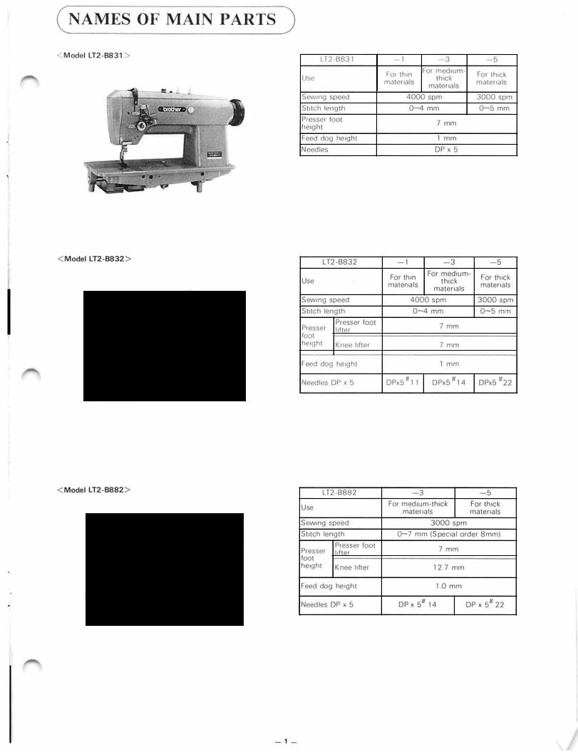
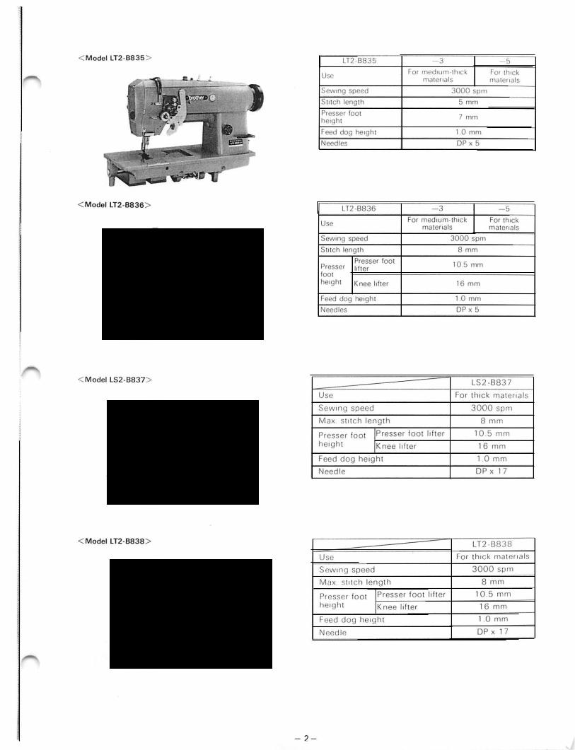
NAMES OF MAIN PARTS)............. |
|
1 |
||||
(SPECIFICATIONS) . . . |
. . . . . |
. . . . . . . . . . |
. . . . |
3 |
||
(MECHANISM) |
........................... |
|
|
|
5 |
|
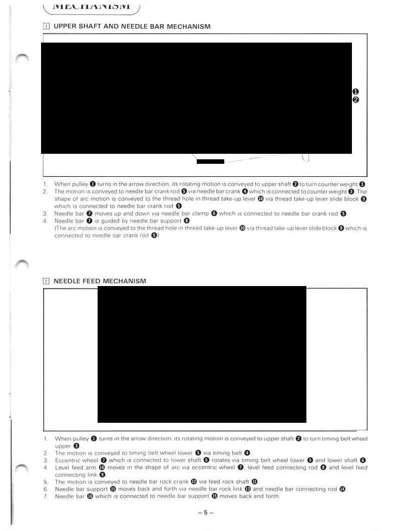
[]Upper shaft and needle . . . . . . .bar mechanism |
• |
5 |
||||
[!)Needle feed mechanism . . . . . . . . . . . . . . . . . . . |
|
• |
• . |
5 |
||
[!] Lower shaft and rotary . . . . . .hook mechanism |
. |
6 |
||||
[!] Feed mechanism |
. . . . . . . . . . . . . . . . . . . . . . .. . • |
• • |
|
. |
6 |
|
III Thread trimmer mechanism . . . . . . . . . . . |
. . • • |
• |
• • . |
7 |
||
[I) Tension releaser mechanism ............... |
|
|
• ;. |
7 |
||
[II Reverse mechanism . . . . . . . . . . . . . . . . . . . . . . |
|
• |
• |
• . |
8 |
|
(!]Thread wiper . . . |
. . . . . . . . . . . . . . . . . . . . . . . . . . . . |
|
|
|
. |
8 |
[!J Needle bar (left and right) mechanism types |
|
|
||||
8835 and 8836 |
. .. . .. .. .. .. . .. .. .. . . .. . .. . .. |
|
|
|
|
9 |
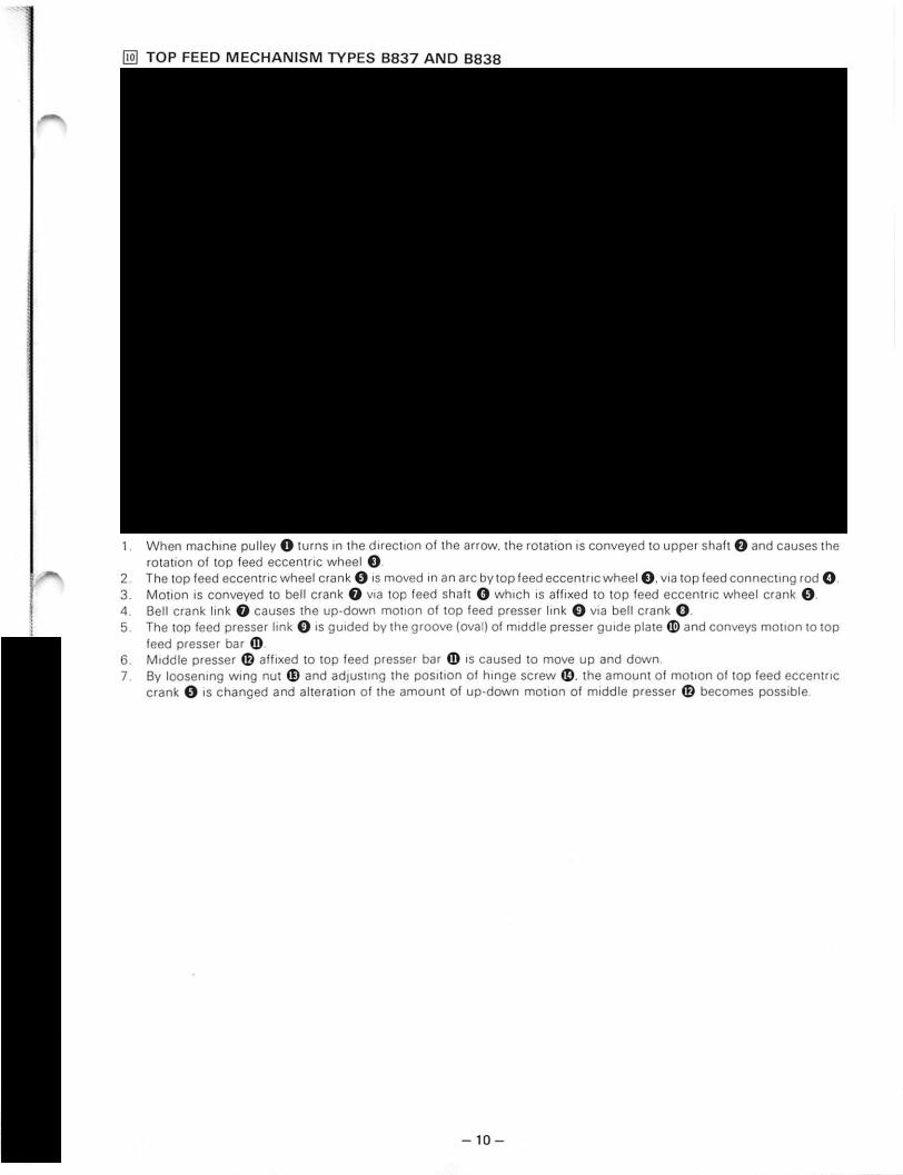
@)Top feed mechanism types 883 7 and 8838 |
|
10 |
||||
DISASSEMBLY PROCEDURES |
|
11 |
||||
B831,B832,B835,B836,8882 |
|
|
||||
[]Cover . • . . . . . . . . |
. . . . . . . . . . . . . . . . . . . . . . . . . . . . . |
|
|
|
|
11 |
[1] Presser mechanism . . . . . . . . . . . . . . . . . . . . . . . . . . |
|
|
|
|
11 |
|
[!]Thread wiper . . • . |
. . . . . . . . . . . . . . . . . . . . . . . . . . . |
|
|
|
• |
12 |
[!]Rotary hook. lower shaft and |
|
|
|
|
||
thread trimmer mechanism . . . . . . . . . . . . . . . |
. • |
|
• • |
12 |
||
III Reverse mechanism . . . . . . . . . . . . . . . . . . |
. . . . . • |
|
• |
• |
14 |
|
[!]Needle bar rocking shaft . . . . . . . . . . .mechanism |
|
15 |
||||
[II Reverse switch mechanism . . . . . . . . . . . . . . . . . |
|
|
• . |
15 |
||
(ASSEMBLY PROCEDURES) ........... |
|
16 |
||||
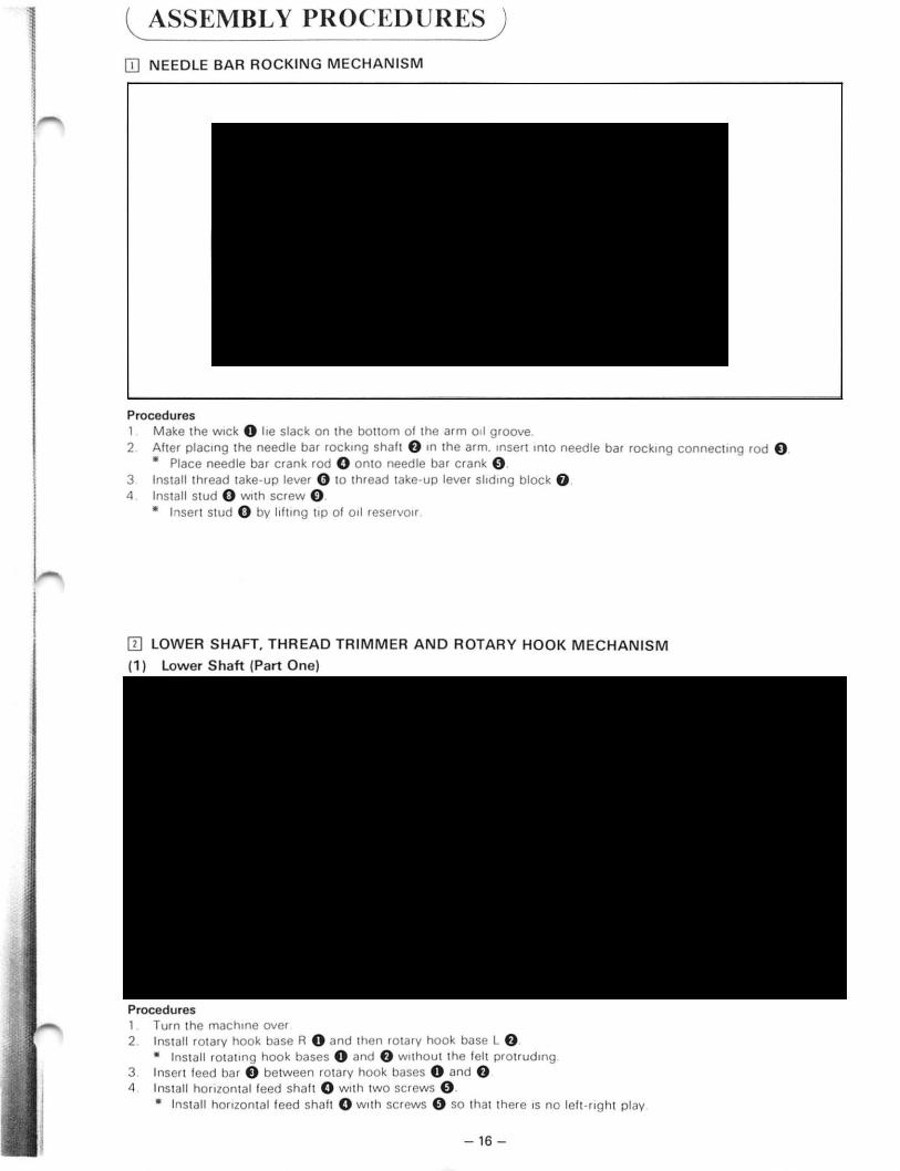
[]Needle bar rocking mechanism . . . . . . . . . . . .. • |
• |
• |
16 |
|||
[1] Lower shaft. thread trimmer and |
|
|
|
|||
rotary hook mechanism . . . . . . . . . . . . . . . . . . . . . |
|
|
• . |
16 |
||
[!] Presser mechanism . . . . . . . . . . . . . . . . . . . . . . . |
|
• |
• |
• |
21 |
|
[!]Thread wiper ....... |
..................... |
•• |
|
|
•• |
21 |
(1] Reverse switch mechanism . . . . . . . . . . . . . . |
. . . . • |
|
|
23 |
||
[!]Reverse mechanism . . . . . . . . . . . . . . . . . . . . . . . . |
|
• |
|
• |
23 |
|
[II Cover • . . . . . . . . . |
• . . . . . . . . . . . . . . . . . . . . . . . . . . |
• |
• |
|
|
24 |
STANDARD ADJUSTMENTS |
. . . . . |
25 |
|
B831,B832,B835,B836,B882 |
|
||
lil Needle and feed t1mmg (8831) |
. . . . . . . . |
. . . . . . . . |
25 |
(1] Adjustment of needle bar to presser bar gap |
|
||
(Models 8831. 8832. 8835. 8836. 8882) . . . . . |
28 |
||
[!]Needle and rotary hook timing adjustment • . . . . . |
29 |
||
[!] Rotary hook to needle plate gap |
. • . . . . . |
. . . . . . . . |
31 |
II] Rotary hook to bobbin case opener gap |
. • • . . . . . |
31 |
|
[!]Presser foot height adjustment |
. . . . . • . . |
. . • • . . . . |
32 |
[II Feed dog height adjustment .. |
.. . . • • . • |
.. . . . . .. |
33 |
(!]Tension release adjustment . • . . |
• . . . . . . |
• • . . . . . . |
34 |
[!]Stitch length adjustment . . . . . . . |
. . • • . . . . |
. . . . . • . |
35 |
(!ID Reverse feed soleno1d adjustment . . . . . . . |
. . . . . . |
36 |
|
[ill Thread wiper adjustment . . . . . . |
. . . . . . . . . |
. . . . . . |
37 |
lliJ Slider adjustment . . . . . . . . . . . . . |
. . . . . . . . . |
. . . . . . |
39 |
[!!]Movable and fixed kn1fe adjustment . . . . . . |
. . . . . . |
40 |
|
IE) Knife mam lever roller . . . . . . . . . |
• . . . . . . . . |
. . . . . . |
42 |
ffi) Knife drcving lever adjuStment . . . |
. . . . . . . . |
. . . . . . |
42 |
@] Position detector adjustment . . . . |
. . . . . . . . |
. . . . . . |
43 |
ill) Corner sewmg pos1t10n adjustment |
|
|
|
(8835. 8836) .. . .. . . . .. . .. .. .. |
.. . . . .. . |
.. .. .. |
43 |
[!!] Timmg belt replacement • . . . . . . . |
. . . . . . . . |
. . . . . . |
4 7 |
From the library of: Superior Sewing Machine & Supply LLC |
\/ |
|

CONTENTS [Model 8837 · 8838]
|
|
|
|
|
|
|
|
|
|
|
|
|
|
|
Page |
DISASSEMBLY PROCEDURES |
|
||||||||||||||
|
48 |
||||||||||||||
B837,B838 |
|
|
|
|
|
|
|
|
|
|
|||||
|
|
|
|
|
|
|
|
|
|
|
|
|
|
||
[I) Cover . . . . . . |
. . . . • . |
. • . • • . . . . . |
. . . . . |
|
. . |
|
. |
. . . . . . . |
. . |
48 |
|||||
[!]Tension release lever . |
. . . . . . . |
. . . . . |
|
. . |
|
. |
. . . . . . . |
. . |
49 |
||||||
[II Presser foot and walking bar . |
. . . . . |
|
. • . • . . . . . . |
. . |
49 |
||||||||||
fl] Needle bar and needle thread take-up |
|
|
. . . . . . . |
. . |
51 |
||||||||||
[I] Feed assembly . . .. |
. . . |
. . . • • .. |
. . .. .. |
|
. |
|
. |
.. . . . .. |
.. |
51 |
|||||
(ASSEMBLY PROCEDURES) ........... |
|
|
|
|
52 |
||||||||||
[I) Feed assembly . . . . . |
. . |
. .. . . . . |
. . • . . . . |
. |
|
. . . . . . . |
. . |
52 |
|||||||
[!]Needle bar . |
. . . . . . . |
. . |
• . . . . . . |
. . • . • . • |
|
. |
. • . . . . . |
• • |
52 |
||||||
[II Walking bar and presser foot |
. . . • . . . |
. |
|
. . . . . . . |
. . |
53 |
|||||||||
fl]Tension release lever ......................... |
|
|
|
|
|
|
|
|
57 |
||||||
[!]Cover .• •... .... |
•.. |
•... |
•.•..•••.............. |
|
|
|
|
58 |
|||||||
|
|
|
|
|
|
|
|
|
|
||||||
STANDARD ADJUSTMENTS |
|
|
.. .. . . .. |
|
59 |
||||||||||
B837,B838 |
|
|
|
|
|
|
|
|
|
|
|||||
|
|
|
|
|
|||||||||||
[I) Needle and feed timing adjustment (standard) |
. . |
59 |
|||||||||||||
[!]Feed dog adjustment m back and forth |
|
|
|||||||||||||
directions . . |
. . . . . . . |
. . . |
. . . . . . |
. . . . . |
. |
. |
. |
|
. . . . . . . . |
. |
60 |
||||
[II Needle and rotary hook timmg adjustment . . . . . |
. |
61 |
|||||||||||||
fl] Clearance between rotary hook and |
|
|
|
|
|
||||||||||
needle plate |
. . • . • . . |
. . . |
• . . . . . . |
. . . . |
. |
. |
. |
|
. . . . . . . . |
. |
62 |
||||
11] Clearance between rotary hook and |
|
|
|
|
|
||||||||||
bobbin .case opener |
. . . |
. . . • . . . |
. . . . |
. |
. . |
|
|
. . . . . . . . |
. |
62 |
|||||
[!] Presser foot height adjustment |
. • . . . . |
• • . . . . . . . |
. |
63 |
|||||||||||
II] Feed dog height adjustment . . |
. . . . |
. |
. . |
|
|
. . • . . . . . |
. |
64 |
|||||||
II] Vibrating presser foot and lifting presser foot |
|
|
|||||||||||||
and needle timing adjustment . |
. . . . |
. |
. . |
|
|
. • . . . . . . |
• |
65 |
|||||||
1IJ Upper feed adjustment |
.. . • • .. |
. . .. |
.. |
. |
|
.. |
. . . . .. |
. |
65 |
||||||
[!ID Vibrating presser foot and lifting presser foot |
|
|
|||||||||||||
vertical stroke adjustment . . . . . |
. . . . |
. |
. . |
|
. |
. . . . . . . |
. |
66 |
|||||||
GAUGE PARTS LIST FOR |
|
|
|
|
DOUBLE NEEDLE LOCK STITCH |
|
|
||
SEWING MACHINES |
|
_, |
..... |
67 |
(OTHERS)................................. |
|
|
|
75 |
[I) Top cover thread guide .. • .. .. |
.. • .. .. |
.. .. |
. .. .. |
75 |
[!]Adjusting upper thread length |
• . . . . . . . |
. . . . . |
. . . • |
75 |
[II Anti-spinning spring .. . .. . .. .. |
.. • . . .. |
. . . .. |
. .. . |
76 |
fl]8obbin ...................... |
•...... |
•........ |
|
76 |
ITlTo thread bobbin cases (8835. 8836) |
........ |
• |
76 |
|
(TROUBLESHOOTING GUIDE) |
......... |
|
77 |
|
From the library of: Superior Sewing Machine & Supply LLC

Ill Motor pulley
Med1um
--------------- |
|
LT2 -B832 -403A |
|
|
LT2 -B83 5-403A |
|
|||||||||||||
|
|
|
|
703A |
|
|
|
|
|
703A |
|||||||||
|
50 Hz |
|
|
|
105 Pulley |
|
105 Pulley |
I |
90 Pulley |
||||||||||
|
|
|
|
|
|
|
|
60Hz |
|
|
50 Hz |
60Hz |
|||||||
|
|
Machine speed |
|
|
4000 spm |
|
|
3000 spm |
|||||||||||
|
|
Motor Pulley |
Size |
120 Pulley |
|
|
|
|
|
|
|
|
l |
|
|
|
|
||
|
|
Part No. |
224545-000 |
|
|
226389-000 |
226389-000 |
224506-001 |
|
||||||||||
|
|
|
|
|
|
||||||||||||||
|
|
Belt Cover |
#No. |
#12-2 |
|
|
#1 2-1 |
|
|
|
#12-1 |
|
|
|
|
||||
|
|
Part No. |
22454 7-001 |
|
|
226393-001 |
226393-001 |
|
|
|
|||||||||
|
|
|
|
|
|
|
|
||||||||||||
|
|
|
|
|
|
|
|
|
|
|
|
|
|
|
|
|
|
||
|
Treadle Unit |
#No. |
|
#5-38 |
|
|
|
|
|
|
#5-30 |
|
|
|
|
||||
|
Part No. |
224396-038 |
|
224396-030 |
|
|
|
||||||||||||
|
|
|
|
|
|
|
|||||||||||||
|
|
Control Box |
v |
110/220V |
• |
|
100/200 v |
|
110/220 v |
• |
100/200 v |
||||||||
|
|
Assembly |
Part No. |
226531-001 |
226426-001 |
226531 -002 |
226426-002 |
|
|||||||||||
Thick |
|
|
|
|
|
|
|
|
|
|
|
|
|
|
|
|
|
||
|
|
|
|
|
|
|
|
|
|
||||||||||
---------- |
|
LT2-B832-405A |
|
|
LT2-B835-405A |
||||||||||||||
|
|
|
|
705A |
|
|
|
|
|
90 Pulley |
|||||||||
|
|
|
|
|
|
|
|
|
|
|
|
|
705A |
||||||
|
|
|
|
|
|
|
|
|
|
|
|
|
LS2-B837 -300A |
||||||
|
|
|
|
|
50 Hz |
I |
|
60Hz |
|
|
50 Hz |
I |
60Hz |
||||||
|
|
Machine speed |
|
|
3000 spm |
|
|
3000 spm |
|||||||||||
|
|
|
|
|
|
|
|
|
|
|
|
|
|
|
|
|
|||
|
|
Motor Pulley |
Size |
105 Pulley |
I |
|
90 Pulley |
|
105 Pulley |
I |
|
|
|
|
|||||
|
|
Part No. |
226389-000 |
224506-001 |
226389-000 |
224506-001 |
|
||||||||||||
|
|
|
|
||||||||||||||||
|
|
Belt Cover |
#No. |
|
#1 2-1 |
|
|
|
|
|
|
#12-1 |
|
|
|
|
|||
|
|
Part No. |
226393-001 |
|
226393-001 |
|
|
|
|||||||||||
|
|
|
|
|
|
|
|||||||||||||
|
|
|
|
|
|
|
|
|
|
|
|
|
|
|
|||||
|
|
Treadle Unit |
.#No. |
|
#5-30 |
|
|
|
|
|
#5-30 |
|
|
|
|||||
|
|
Part No. |
224396-030 |
|
224396-030 |
|
|
|
|||||||||||
|
|
|
|
|
|
|
|||||||||||||
|
|
|
|
|
|
|
|
|
|
|
|
|
|
||||||
|
|
Control Box |
v |
110/220 v |
• |
|
100/200 v |
|
110/220 v |
• |
100/200 v |
||||||||
|
|
Assembly |
Part No. |
226531-002 |
226426-002 |
226531-002 |
226426-002 |
|
|||||||||||
|
|
|
|||||||||||||||||
|
|
|
|
|
|
|
|
|
|
|
|
|
|
|
|
|
|
|
|
•When ordering a motor be sure to specify the sewing mach1ne model number. intended matenals to be used. and either single or three phase.
•Parts in the above table are for both smgle and three phase machines.
•Machines and motors for voltages other than those specified above can be manufactured to order. Consult your local dealer.
•Be sure to refer to the parts book when ordermg any parts.
(2)Motor pulley change
*Use the V-belt included together with the machme
head. After installing the belt. loosen both hexagon nuts 0. and adjust the tens1on of the belt. Make sure
that the correct belt tension is mamtained. Then tighten the hexagon nuts.
• The belt can be depressed about 10 mm w1th a f1nger.
From the library of: Superior Sewing- 4- Machine & Supply LLC


IT] THREAD TRIMMER MECHANISM
~.
i
l
lr
I
I
r
!
i
!
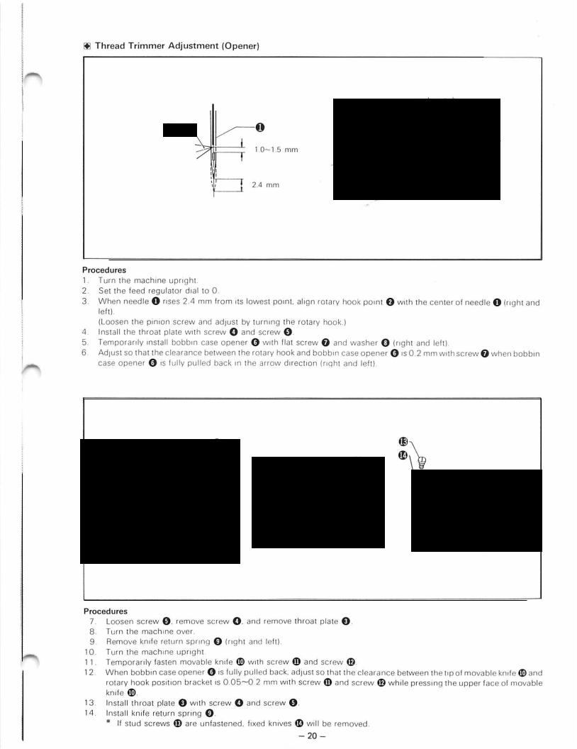
1. When thread trimming signal comes from synchronizer. solenoid 8 is ON and plunger 8 is pulled in the arrow
|
direction. |
2. |
The motion is conveyed to knife driving pin lever 8 via knife driving lever 8. |
3. |
As knife main lever shaft 8 is pushed in the arrow direction. knife main lever roller 8 enters knife driving cam recess e |
|
which is connected to lower shaft 8. |
4. |
According to the recess shape of knife driving cam e. the motion is conveyed to knife lock arm 6) via knife main lever |
|
8. knife sub lever 0. knife length adjusting link CD. knife lock lever right 4D and knife lock arm shaft G) (right slider side). |
5. |
The motion is conveyed to knife lock arm 6) via knife link 4B which is connected to knife lock lever right 49. knife lock |
|
lever left G) and knife lock arm shaft G) (left slider side). |
6. |
Movable knife 0 which is connected to slider fD is moved in the arrow direction. |
7. |
The movable knife 0 returns while the roller of knife main lever 8 is being controlled by the shape of knife driving cam |
|
e. |
8.After returning movable knife solenoid 8 is OFF. and knife main lever roller G is released from knife driving cam recess
~e.
[[] TENSION RELEASER MECHANISM
.II
I
l
J
I
I
1. When thread trimming signal comes from synchronizer. solenoid 8 is ON and plunger 8 is pulled in the arrow direction.
2. The motion is conveyed to knife driving pin lever 8 via knife driving lever 0.
3.As knife main lever shaft 8 is pushed in the arrow direction. tension release lock lever 0 is connected with tension release cam portion of knife driving cam 8.
4.Roller of tension release lock lever 8 is pushed in the arrow direction by tension release cam portion of knife driving
~cam8.
5.The motion is conveyed to tension release crank G) via tension release connecting rod lower e. tension release crank lower 0. tension release crank upper CD tension release connecting rod upper 4D and tension release plate 8.
6.As tension release crank G) pushes presser bar lifter 41). tension disc 0 is moved via tension release bar 41. tension release plate fD and pin.
7.When solenoid 8 is OFF. t'ensiondisc is returned to its original position.
From the library of: Superior- 7Sewing- Machine & Supply LLC

[[] NEEDLE BAR (left and Right) MECHANISM TYPES 8835 and 8836
l
|
|
(To Stop the Right Side Needle Bar) |
|
|
|
1. |
Move stop lever assembly 0 to the right side. (Push lever f) rises. and the convex part of the back s1de of stop lever 0 |
|
|
|
attaches to push lever f) and stops.) |
|
|
2. |
Lever shaft arm 8 and slide shaft 0 are moved to the right side via lever shaft arm 8 which is attached to stop lever |
|
|
|
assembly O. |
|
|
3. |
The slide bearing board assembly 8 which fits in slide shaft 0 moves to the right side via collar 8 and bearing board |
|
|
|
spring 0. |
|
|
4. |
The pin which is attached to the tip of thrust bearing board assembly 8 moves sliding block operation shaft G) to the left |
|
|
|
side via moving crank 0. |
|
|
|
|
|
|
5. |
Sliding block assembly 48 is moved to the right side via sliding block operation lever CD which fits in the pin screw affixed |
|
|
|
to sliding block operation shaft G). |
|
|
6. When the convex part of sliding block assembly fB contacts the clutch lever of needle bar connecting stud 41 attached |
|
|
|
|
to needle bars fl). the clutch in needle bar connecting stud 41 breaks away from needle bar~. and needle bar fl) stops. |
I |
|
||
|
• When the left side needle is caused to stop. the reverse sequence is performed. |
||
I |
(Cancellation of Needle Bar Termination) |
||
J |
1. |
When push lever f) is pressed. it becomes loosened from the convex part of the back side of stop lever 0 and is |
|
|
returned to its original position by lever shaft arm CD. |
||
|
|
|
|
|
|
2. |
When stop lever 0 is returned to the middle position by lever shaft arm spring&. sliding block assembly fB returns to |
J |
|
center position via slide shaft 0. slide bearing board assembly 0. moving crank 0. sliding block operation shaft G>. |
|
|
sliding block operation lever CD. etc. |
||
I |
|
||
3. |
The release pin of needle bar connecting stud 41 is pushed by the convex part of sliding block assembly CD and the |
||
|
clutch fits into needle bars fl) again. |
||
4. |
Needle bar G) can be raised and lowered. |
||
I |
|
|
|
From the library of: Superior Sewing Machine & Supply LLC
- 9 -

~ UISASS.EMHL Y .PKUC.EU lJK.ES)
•These disassembly procedures are for model l T2 -8832 -403A. Other twin needle lock stitch machines may be disassembled on the basis of these procedures.
ITJ COVER
Procedures
1.Loosen thumb screw 0. remove step screw 8 and washer 8. and remove the face plate 8.
2.Remove two screws 8 and remove top cover 0.
3.Remove bed slideR G and bed slide L 0.
4.Loosen screw Cl) and remove bed slide F 4]).
5.Remove two screws 4B and remove cover G).
6.Remove two screws CD and remove synchronizer cover 49 and washer (D.
7.Remove two screws 41 and remove needle position detector G).
[]]PRESSER MECHANISM
Procedures
1.Loosen two screws
2.Loosen two screws
0 and remove two needles f).
8 and remove thread wiper R 8 and thread wiper L 8.
3.Remove screw 0 and. after raising presser lift lever 8. remove presser foot 0.
4.Remove stud screw CD and remove knee lifter lever spring CD and knee lifter lever G).
5.Remove two screws 48 and connecting rod knee lifting joint ball bearing 8. Remove tension release connecting rod CD (tension release indicating plate.)
6.Loosen presser adjustment screw 0 and remove spring Cl).
7.Remove presser bar lifter guide 8.
8.Loosen flat screws G) and remove presser bar G). (Presser bar guide bracket fD. presser bar lifter fl. and presser bar guide fJ) disconnect.)
•Tension release shaft e disconnects when the machine is turned over.
From the library of: Superior-11Sewing- Machine & Supply LLC

[!] THREAD WIPER
trri-==f)~ c:====~~Termrnal prn
.reD |
12-prn plug |
c(~a.> |
|
.........
Termmal prn |
Terminal p1n |
(black) |
(white) |
Procedures
1.Remove thread wiper spring O.
2.Remove plunger pin O.
-3. Remove solenoid link 0. thread wiper assembly 0. and rubber stopper 0.
4.Remove three flat screws 8 and remove thread wiper solenoid cover 0.
5.Remove four screws 0 and remove three cord braces 0.
6.Remove four flat screws CD and remove solenoid f). (Remove terminal pm from the 12-p1n plug.)
ffi ROTARY HOOK, LOWER SHAFT AND THREAD TRIMMER MECHANISM
(1)Rotary Hook
Procedures
1.loosen screw 0 and remove screw f); then remove throat plate 0.
2.Remove flat screw 0 and remove bobbin case opener 0 and washer 0 (nght and lef_t).
3.Turn over the mach1ne.
4.loosen three screws 8 (nght and left screws).
5.Remove two thread cutter return spnngs 0.
6.Turn the mach1ne upnght.
7.Remove screws 0 0 and remove movable kn1fe CD.
8.Turn the machme pulley and move the needle bar to the h1ghest pomt.
9.Remove two screws CD and remove feed dog CD.
10.Remove rotating hook fD and spacer CD (right and left).
• Be sure not to confuse the right and left rotary hooks fD and spacers CD when assembling.
From the library of: Superior Sewing-12- Machine & Supply LLC

(2)Thread Trimmer
lever relurn s~l~lf |
12-prn plug |
|
- |
|
|
|
|
|
|
|
fB~!~~~~. - |
|
|
|
~~---• |
: -~ |
|
Termmal pm (whrte) |
|
|||
C) |
A L fB |
Termrnal prn |
|
|
~(@ |
|
(black) |
Procedures
1. Remove two screws 0 and remove tension release connectmg rod 8.
2.Remove tension release return spring 0.
3.Turn the machine over.
4.Remove two ball joint stud screws 0 and remove connecting rod assembly 0.
5.Remove two ball joint stud screws 0 and remove length adjustment connecting bar assembly 8.
6.Loosen screw 8 and remove pin lever 0 (shaft and forked lever).
7.Loosen screw 41) and remove sub lever shaft fD.
8.Loosen screw with hole$ and remove main lever shaft fl. tension release moving assembly e (main lever return spring). and rubber Gl.
9.Remove two flat screws 4D and remove thread tnmmer solenoid (D. (Remove the prn terminal from the 12-prn plug.)
(3)Lower Shaft
Procedures
1.Remove t1mrng belt 8.
2.Remove switch mechanism sprrng G.
3.Remove screw 0 and remove spring peg O.
4.Remove flat screw 0 and remove feed bar fork 0 and washer 8.
5.Loosen screw 8 and remove set screw f).
6.Loosen two screws 41).
7.Loosen three screws fD (nght and left)
8.Loosen screw 8.
9.Loosen screw G) and two screws e. and remove timrng pulley 0 Gl.
10.Remove three screws fD and remove beanng presser fD.
11.Remove lower shaft 1). (At this time pinion G>. vertical feed eccentric wheel fl. horrzontal eccentric wheel fD. knife
driving cam fl. and spiral gear f1 disconnect.)
• Place pinion G) and spiral gear fi in therr respective rotating hook positions. (Be sure not to misinsert them.)
From the library of: Superior Sewing Machine & Supply LLC
-13-

(4)Thread Trimmer and Rotary Hook
Procedures
1.
2.
3.
4.
5.
6.
L 7. 8.
9.
10.
Loosen screw 0 (right and left).
Remove screw f) and remove washer 0 (right and left). Loosen screw 8 and remove set screw 8 (right and left).
Remove lever L assembly 0 (moving shaft) and remove rocking arm 8. Remove lever R assembly 0 (moving shaft) and remove rocking arm f). Turn the machine upright.
Remove two flat screws 0 and remove slider assembly 4D (nght and left). Turn the machine over.
Loosen two screws 4D and screws fD and ~- and raise feed bar G) forward. Remove rotary hook baseL 49 and then rotary hook base R CD.
[[] REVERSE MECHANISM
12-pm plug
Term1nal pm (black)
Terminal pm (wh1te)
Procedures
1.Turn the machine upright.
2.Remove screw 0 and remove reverse solenoid cover f).
3.Remove stud screw 0.
4.Remove three flat screws 8 and remove reverse solenoid bracket 8.
5.Remove the pin terminal from the 12-pin plug.
-14-
From the library of: Superior Sewing Machine & Supply LLC

[II NEEDLE BAR ROCKING SHAFT MECHANISM
Thread take-up lever
Procedures
1.Remove two flat screws 8 and remove side plate f).
2.Loosen screw f).
3. Loosen screw 8 and remove thread take-up shaft 0 while raising the tip of oil regulator reservoir 0.
4.Remove thread take-up lever 8. (The thread take-up lever slide block disconnects.)
5. Insert a wedge to needle bar rocking connecting bar 0 and remove needle bar rocking shaft assembly 0.
[I] REVERSE SWITCH MECHANISM
Term1nal pin (black)
Termmal pin (wh1te)
Procedures
1. Loosen flat screw 8 and remove actuator bar f).
2.Remove two flat screws 8 and remove micro switch case 8 and washer 0.
3.Remove two screws 0 and remove micro switch f).
4.Remove the terminal pin from the 12-pin plug.
-15-
From the library of: Superior Sewing Machine & Supply LLC

Lower Shaft (Part Two)
Procedures
5.As shown 1n the diagram. place the lower shaft m 1ts bed and 1nstall 1n the followmg sequence: knife driving cam f). horizontal eccentric wheel Cl). spiral gear C). vertical feed eccentric wheel«!). and Spiral gear C) onto lower shaft 0.
6.Fasten bearing presser 4D with screw 0.
7. Install timing pulley 0 f» to lower shaft 0 with screw G) and screw$.
|
• Tighten screw G) to screw seat of lower shaft O. |
|
8. |
Install knife driving cam f) to lower shaft 0 with set screw 4D and screw 0). |
|
|
• |
Tighten set screw ~ to screw seat of lower shaft 0 and then fasten screw 0). |
9. |
Install horizontal eccentric wheel 0 with two screws Cl). |
|
|
• |
Tighten screw 41 in front of lower shaft 0 rotating d1rect1on to the screw seat |
10. |
Install vertical feed eccentric wheel «!> w1th screw CB. |
|
•Tighten screw CB to screw seat.
(2)Thread Trimmer and Rotary Hook
|
|
fD |
|
|
spacen~-.. spacer |
||
|
fJ) |
~ |
Cfj |
|
|
|
f) |
|
|
|
|
Procedures |
|
|
|
11 . Turn the machine upright. |
e and 8 With two flat screws • |
|
|
12. Install slider assembly 0 to rotary hook bases |
(nght and left). |
||
• Verify that slider assembly 0 operates smoothly (right and left).
13.Turn the machine over.
14.Insert lever L 0 and rockmg arm shaft 0 to rotary hook base 8. and install rockmg arm f) with set screw 0 and screw 0.
15.Insert lever assembly R «!)and rockmg arm shaft 0 to rotatmg hook base 8. and mstall rocking arm f) with set screw
~0 and screw f).
16.Temporarily fasten rotary hook bases 8 and 8 with screw 0 and washer 0 (nght and left).
17.Insert feed bar fork G) to vertical feed eccentric wheel G) and install with flat screw 41 and washer ~.
18.Place pinion 0) into grooved portion of rotary hook bases 8 and 0.
19.Place rotary hooks G) (spacer) on rotary hook bases 8 and 8 and pinion 0). and then temporarily fasten with screw
20. |
•• |
~with |
two screws f». |
Temporarily fasten feed dog |
|
||
|
From the library of: Superior- Sewing Machine & Supply LLC |
||
|
|
|
17- |
Ill Feed Dog Position Adjustment
Procedures
1.Set the feed adjustment dial to 0. (This sets the feed amount to zero.)
2.Install throat plate 0 with screws 8 and 8.
3.Install needle Gin needle clamp 0 with screw G.
4.Place presser bar 8 into jaw part of arm.
5.Turn the machine over.
6.Loosen four screws 0 and adjust with the horizontal feed shaft tii> so that feed dog 0 moves left and right in the opening of throat plate 0. (After adjusting. fasten securely with screws 0 so that there is no play in horizontal feed shaft tii).)
7.When feed dog 0 is at its highest position. loosen screw fD and adjust with feed bar 48 so that the distance from throat
plate 0 surface is 1 mm for medium-thick materials and 1-1 .2 mm for thick materials. (Fasten screw fD securely.)
8.Holding the distance of 13.5 mm between needle bare and presser bar 8. fasten horizontal feed arm screw. at the posit1on where the tip of needle 0 enters the center of feed dog 0 needle hole. Afterwards. fasten screws CD and 4D in
that order.
• Fasten screw fl when the needle bar rocking crank 0 1s at the center of its swmg.
•Adjust to 14.2 mm m step 0 above w1th models 8835 and 8836.
Ill Rotary Hook Base Position Adjustment
Procedures
1. Remove the throat plate.
2.After aligning the dot mark of sp1ral gear 0 and pinion 8. temporanly fasten screw 8 to the screw seat of the lower shaft.
3.Adjust to a clearance of 0.05 mm between the rotary hook pomt and needle 0 by movmg the rotary hook bases (Rand L)
|
when the needle rises 2.4 mm from the lowest positiOn. and tighten screws 0 and 0. |
4. |
Fasten screw 8 and two screws 8 so that a 0.2 mm space is between the rotary hook base and spiral gear O. |
5. |
Loosen screw 0 and then fasten with the rotary hook point at the center of needle 8. |
•The above adjustment is for thread cutter sewing machines. Figures for other models may vary from those give here.
From the library of: Superior Sewing-18-Machine & Supply LLC

(3)THREAD TRIMMER
~!l
~
Procedures
1. As shown above. place tension release rocking lever 0. main bar return spring 8. main lever assembly 8. and rubber 8 into base bracket 8 and insert through with main lever shaft 0 and then install with screw 8.
2.Install thread trimmer solenoid 8 with screw 0.
3.Place groove of sub lever G) to the slide block of main lever assembly 8 and pass sub lever shaft CD through sub lever G) and base bracket 0. Install with screw $.
4. |
Install |
connecting rod G) to lever l CD and lever R CD with screw 4D. |
5. |
Install |
length adjusting connecting rod 4J) to lever R CD and sub lever 0 with screw CD. |
6.Attach knife return spring G).
7.Adjust with screw 8 so that there is a space of 5 mm between rubber 8 and base bracket 8.
8.When main lever shaft 0 is pressed. adjust with screw tD so that the roller of knife main lever 8 can easily enter the recess of knife driving cam e.
Red dot |
T mark |
o/Thread presser spnng |
||
|
||||
|
|
|
o.5mm |
Shder |
|
|
|
|
|
|
|
|
|
|
|
|
12-pin plug |
|||
|
|
Termmal prn (black) |
|||
|
|
00 |
|
|
|
|
|
Termrnal pm (white) |
|
|
|
..· |
|
|
|
|
|
|
|
||||
Procedures |
|||||
|
9. |
Fit fork lever and screw 0 to the forked part of the plunger. |
|||
|
10 Place pin lever and screw f» and shaft f) to fork lever 0. |
||||
|
11. |
Fasten with screw f1' so that there is a space of 0.5 mm between base bracket 8 and fork lever 0. |
|||
|
12. |
Push main lever shaft 0 and turn lower shaft fJ until it is difficult to turn. |
|||
|
13. |
Align the T mark on the pulley with the dot on the machine head and attach the timing belt f). |
|||
|
14. |
loosen screw tl and adjust with moving knife rocking arm e so that there is a clearance of 0.5 mm between the slider |
|||
|
|
and slider base 8 (right and left). |
|||
|
15. |
Install spring peg fD with screw G. |
|||
|
16. |
Install tension release connecting rod G with screw G). |
|||
|
17. Install spring G and spring (b. |
||||
|
18. |
Install the terminal pin to the 12-pin plug. |
|||
From the library of: Superior -Sewing19- Machine & Supply LLC

[I] PRESSER MECHANISM
Center of presser grooves
Metal bushmg
Procedures
1.From the top of the arm. place presser bar guide 0. presser bar lifter 0. and presser bar bracket 8 1n that order on
presser bar 0 as shown in the figure above.
• Make sure the tens1on release shaft 0 is installed in the arm.
2.Install presser bar lifter gUide 0 and collar 8 (-400 type) to the arm.
3.Install presser 0 to presser bar 0 with screw 0.
•Install so that the center of the needles match the center of the grooves in presser 0.
4.Raise the presser 0 7 mm from the throat plate surface. (Presser foot he1ght d1ffers according to the spec1f1c model.)
5.Lift presser lifter 0. make presser bar guide 8 contact presser bar lifter 0. and fasten with screw CD.
6.Lower presser lifter (!) and attach presser plate spring fB to presser bar bracket G.
7. |
Fasten screw G) so that there is a space of 1 mm between presser bar bracket 8 and the metal bushmg. |
8. |
Install tension release plate fB and tension release connecting rod (D with two screws 4D and screw fD_ |
9 Install knee lift lever CD and knee lift lever spring fD with stud screw fli). |
|
|
(Attach knee lift lever spr1ng fD to knee lift lever .:D.) |
!11! |
Presser Pressure |
|
AdJUSt by turning presser adJustment screw tD. |
II) THREAD WIPER
Procedures
1. Remove needle 0 and presser f).
2.Install thread wiper soleno1d 8 w1th four flat screws 8 and washers 8.
3. Install thread wiper link 0 and solenoid link 8 with flat screw 0.
4.Install plunger 0 and soleno1d l1nk f) With plunger pin (!).
~• Be sure to insert rubber stopper &.
5.Attach thread wiper spring CD.
6.Install presser f) and needle 0.
7. Install thread wiper L G) and thread w1per R 4D with two screws (D.
8.Install solenoid cover 4D with flat screw 0.
9.Install the terminal pin to the 12-pm plug.
• Refer toFrompage 3 7thefor threadlibrarywiperof:adJUStmentSuperior. Sewing Machine & Supply LLC
-21-

II] REVERSE SWITCH MECHANISM
- 0
12-pin plug
Terminal pin (white)
Procedures
1. Pass the cord through micro switch cover 0.
2.Install micro switch f) with screws 0.
3.Install actuator bar 0 with screw 4:).
4.Install micro switch cover 0 with screws 0 and washers 8.
5.Install the thread wipe~ cord and reverse switch cord with two cord braces 0 and two screws 0.
6.Install the terminal pin to the 12-pin plug.
7.Adjust actuator bar play with stop screw 0. and then tighten nut ~.
From the library of: Superior Sewing-22-Machine & Supply LLC

[!] REVERSE MECHANISM
Termmal pm (black) 12-pm plug
Reverse switch cord
Thread wiper cord
Reverse solenoid
Terminal pin (white)
Procedures
1.Install rear cover 0 with two screws 8.
2.Set the reverse crank 0 fork on the reverse solenoid plunger 8.
3. Secure the reverse crank 0 to the solenoid base 8 with screw f).
4.Secure solenoid base 8 with screw f).
5.Secure reverse link 0 and reverse crank 0 with screw 0.
6.Secure the cords with the cord clamp Gi) and screws CD.
7.Install reverse solenoid cover f) with screw$.
8.Install terminal pin to the 12-pin plug.
Ill REVERSE ASSEMBLY ADJUSTMENT
1. Set the feed regulator dial to the maximum setting. 2. Loosen screw fD and raise the reverse soleno1d plunger G until 1t hits the back of the cylinder.
Pull the reverse handle 49 all the way down. and firmly tighten the set screw e.
From the library of: Superior-Sewing23- Machine & Supply LLC
 Loading...