


BE-1204B-BC BE-1204C-BC BE-1206B-BC
SERVICE MANUAL
Please read this manual before making any adjustments
TWELVE NEEDLE FOUR HEAD EMBROIDERY MACHINE
TWELVE NEEDLE FOUR HEAD EMBROIDERY MACHINE<WIDE AREA> TWELVE NEEDLE SIX HEAD EMBROIDERY MACHINE
From the library of Superior Sewing Machine & Supply LLC - www.supsew.com
This service manual is intended for BE-1204B, 1204C, 1206B; be sure to read the BE-1204B, 1204C, 1206B instruction manual before this manual.
Carefully read the “SAFETY INSTRUCTIONS” below and the whole of this manual to understand this product before you start maintenance.
As a result of research and improvements regarding this product, some details of this manual may not be the same as those for the product you purchased.
If you have any questions regarding this product, please contact a Brother dealer.
SAFETY INSTRUCTIONS
1 Safety indications and their meanings
This service manual and the indications and symbols that are used on the machine itself are provided in order to ensure safe operation of this machine and to prevent accidents and injury to yourself or other people. The meanings of these indications and symbols are given below.
Indications
DANGER |
The instructions which follow this term indicate situations where failure to follow the |
|
instructions will almost certainly result in death or severe injury. |
||
|
|
|
CAUTION |
The instructions which follow this term indicate situations where failure to follow the |
|
instructions could cause injury when using the machine or physical damage to |
||
|
equipment and surroundings. |
|
Symbols |
|
|
-------- This symbol ( |
) indicates something that you should be careful of. |
|
The picture inside the triangle indicates the nature of the caution that must be taken. (For example, the symbol at left means "beware of injury".)
 --------- This symbol (
  ) indicates something that you must not do.
--------- This symbol ( ) indicates something that you must do.
The picture inside the circle indicates the nature of the thing that must be done. (For example, the symbol at left means "you must make the ground connection".)
BE-1204B-BC • BE-1204C-BC • BE-1206B-BC |
1 |
From the library of Superior Sewing Machine & Supply LLC - www.supsew.com

2 Notes on safety
 DANGER
Wait at least 5 minutes after turning off the power switch and disconnecting the power cord from the wall outlet before opening the face plate of the control box. Touching areas where high voltages are present can result in severe injury.
 CAUTION
Environmental requirements
Use the sewing machine in an area which is |
The ambient temperature should be within the |
|
free from sources of strong electrical noise |
range of 5°C to 35°C during use. |
|
such as high-frequency welders. |
Temperatures which are lower or higher than this |
|
Sources of strong electrical noise may cause |
may cause problems with correct operation. |
|
problems with correct operation. |
The relative humidity should be within the range of |
|
|
||
Any fluctuations in the power supply voltage |
45% to 85% during use, and no dew formation |
|
should be within ±10% of the rated voltage for |
should occur in any devices. |
|
the machine. |
Excessively dry or humid environments and dew |
|
Voltage fluctuations which are greater than |
formation may cause problems with correct |
|
this may cause problems with correct |
operation. |
|
operation. |
Avoid exposure to direct sunlight during use. |
|
|
||
The power supply capacity should be greater |
Exposure to direct sunlight may cause problems |
|
than the requirements for the sewing |
with correct operation. |
|
machine's electrical consumption. |
In the event of an electrical storm, turn off the |
|
Insufficient power supply capacity may cause |
||
power and disconnect the power cord from the |
||
problems with correct operation. |
||
wall outlet. |
||
|
||
The air supply should have a capacity greater |
Lightning may cause problems with correct |
|
than the machine consumption. If air is not |
operation. |
|
supplied sufficiently, a machine malfunction |
Do not use this machine outdoors. |
|
may occur. |
||
|
Installation
Machine installation should only be carried |
Be sure to connect the ground. If the ground |
|
out by a qualified technician. |
connection is not secure, you run a high risk of |
|
Never operate the sewing machine with any |
receiving a serious electric shock, and problems |
|
with correct operation may also occur. |
||
ventilation openings blocked. |
||
When securing the cords, do not bend the cords |
||
Keep the ventilation openings of the sewing |
||
excessively or fasten them too hard with staples, |
||
machine free from the accumulation of lint or |
||
otherwise there is the danger that fire or electric |
||
dust. |
||
shocks could occur. |
||
Contact your Brother dealer or a qualified |
||
Be sure to wear protective goggles and gloves |
||
electrician for any electrical work that may |
||
when handling the lubricating oil or grease, so that |
||
need to be done. |
||
no oil or grease gets into your eyes or onto your |
||
The sewing machine weighs approximately |
||
skin, otherwise inflammation can result. |
||
700 kg. |
||
Furthermore, do not drink the oil or grease under |
||
The installation should be carried out by four |
||
any circumstances, as they can cause vomiting |
||
or more people. |
||
and diarrhoea. |
||
Do not connect the power cord until |
Keep the oil out of the reach of children. |
|
installation is complete, otherwise the |
Secure the machine with the adjustment bolts on |
|
machine may operate if the start switch is |
||
the sound floor so that it will not move. |
||
pressed by mistake, which could result in |
||
|
||
injury. |
|
2 |
BE-1204B-BC • BE-1204C-BC • BE-1206B-BC |
From the library of Superior Sewing Machine & Supply LLC - www.supsew.com
Installation
Avoid setting up the sewing machine near sources of strong electrical noise such as high-frequency welding uipment.
If this precaution is not taken, incorrect machine operation may result.
 CAUTION
Sewing
This sewing machine should only be used by operators who have received the necessary training in safe use beforehand.
Keep children away from the sewing machine.
The sewing machine should not be used for any applications other than sewing.
Be sure to wear protective goggles when using the machine.
If goggles are not worn, there is the danger that if a needle breaks, parts of the broken needle may enter your eyes and injury may result.
Always use the proper needle plate. Any wrong plate can cause needles to break.
Do not use a bent needle.
Attach all safety devices before using the sewing machine. If the machine is used without these devices attached, injury may result.
Do not touch any moving parts, press any objects against the machine, or pull/push the cloth during sewing. Doing so may result in personal injury, machine damage, or needle breakage.
Do not touch the pulse motor and sewing machine bed section during operation or for 30 minutes after operation. Otherwise burns may result.
Never drop or insert foreign objects or a screwdriver into the ventilation openings or the machine inside.
Touching any high-voltage area may result in an electric shock.
Never damage, alter, heat, or put a strain on the power cable as well as other cables. Doing so may result in a fire or an electric shock.
Turn off the power switch at the following times, otherwise the machine may operate if the start switch is pressed by mistake, which could result in injury.
•When threading the needle
•When replacing the bobbin and needle
•When not using the machine and when leaving the machine unattended
•When cleaning the machine.
Do not get on the table. Table may be damaged.
Do not operate this machine where aerosol (spray) products are being used or where oxygen is being administered.
If the controller is exposed to water or a chemical agent or if its entry is found inside the controller, turn off the power switch immediately. Continuing to use the machine under such a condition may result in a fire or an electric shock.
If an error occurs in machine operation, or if abnormal noises or smells are noticed, immediately turn off the power switch. Then contact your nearest Brother dealer or a qualified technician.
If the machine develops a problem, contact your nearest Brother dealer or a qualified technician.
Cleaning
Turn off the power switch before starting any cleaning work, otherwise the machine may operate if the start switch is pressed by mistake, which could result in injury.
Be sure to wear protective goggles and gloves when handling the lubricating oil or grease, so that no oil or grease gets into your eyes or onto your skin, otherwise inflammation can result. Furthermore, do not drink the oil or grease under any circumstances, as they can cause vomiting and diarrhoea.
Keep the oil out of the reach of children.
BE-1204B-BC • BE-1204C-BC • BE-1206B-BC |
3 |
From the library of Superior Sewing Machine & Supply LLC - www.supsew.com

Maintenance and inspection
Disassembly, assembly, maintenance and |
If the power switch needs to be left on when |
||
inspection of the sewing machine should only |
carrying out some adjustment, be extremely |
||
be carried out by a qualified technician. |
careful to observe all safety precautions. |
||
Ask your Brother dealer or a qualified |
Use only the proper replacement parts as |
||
electrician to carry out any maintenance and |
specified by Brother. |
||
inspection of the electrical system. |
When replacing a fluorescent lamp, use the |
||
Turn off the power switch and disconnect the |
same-type lamp having a rating of 40 watts. |
||
Wait until the fluorescent lamp cools off before |
|||
power cable (do not pull on the cable itself) |
|||
replacement. Failure to do so can result in |
|||
from the wall outlet before attempting to |
|||
burns. |
|||
perform the following operations. Otherwise, |
|||
|
|||
the machine is started if the start switch is |
If any safety devices have been removed, be |
||
pressed by mistake. Injury may occur in |
absolutely sure to re-install them to their original |
||
such a case. |
positions and check that they operate correctly |
||
• |
When carrying out inspection, adjustment, |
before using the machine. |
|
|
|||
|
or maintenance |
Any problems in machine operation which result |
|
• |
When replacing consumable parts such as |
from unauthorized modifications to the machine |
|
will not be covered by the warranty. |
|||
|
a rotary hook, a knife, or a fluorescent lamp |
||
|
|
||
4 |
BE-1204B-BC • BE-1204C-BC • BE-1206B-BC |
From the library of Superior Sewing Machine & Supply LLC - www.supsew.com

3 Warning labels
* The following warning labels appear on the sewing machine.
Please follow the instructions on the labels at all times when using the machine. If the labels have been removed or are difficult to read, please contact your nearest Brother dealer.
1 Electric shock danger display
W1408Q
2 Electric shock danger display |
3 Injury warning display |
Hazardous voltage will cause injury.
W1410Q
4Injury caution display
W1200Q
5Injury caution display
W1202Q
BE-1204B-BC • BE-1204C-BC • BE-1206B-BC |
5 |
From the library of Superior Sewing Machine & Supply LLC - www.supsew.com
6Injury caution display
Never touch or push the thread take up during operation as it may result in injuries machine.
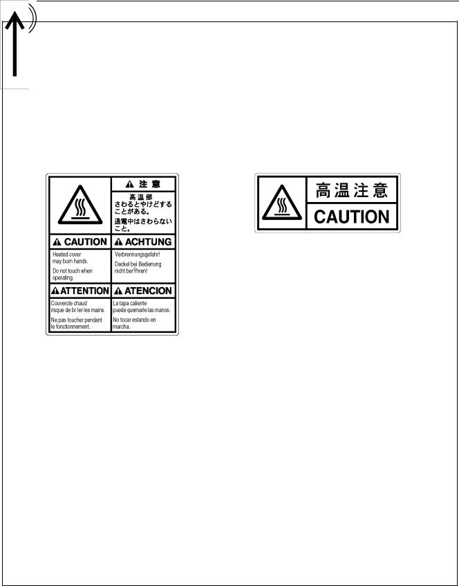
8High temperature caution display
W1201Q
7Injury caution display
Never touch or push the needle bar during operation as it may result in injuries or damage to the sewing machine.
9High temperature caution display
W1206Q
Do not touch this part during activitation or for 30 minutes after shut-off. Otherwise burns may result.
10 Ground mark
Be sure to connect the ground. If the ground connection is not secure, you run a high risk of receiving a serious electric shock, and problems with correct operation may also occur.
11 Direction of operation
W1205Q
6 |
BE-1204B-BC • BE-1204C-BC • BE-1206B-BC |
From the library of Superior Sewing Machine & Supply LLC - www.supsew.com

6
7
5
4
5
2
10
1
W1400Q
9
8
8 |
8 |
4
3
11
4
4
W1208Q
BE-1204B-BC • BE-1204C-BC • BE-1206B-BC |
7 |
From the library of Superior Sewing Machine & Supply LLC - www.supsew.com

Contents
Contents
Chapter 1 |
Mechanical Descriptions |
|
|
1. |
Feed guide mechanism............................................................................................................................................ |
1-1 |
|
2. |
Crank shaft mechanism ........................................................................................................................................... |
1-2 |
|
3. |
Presser foot mechanism.......................................................................................................................................... |
1-3 |
|
4. |
Thread take-up mechanism ..................................................................................................................................... |
1-4 |
|
5. |
Needle bar mechanism ........................................................................................................................................... |
1-5 |
|
6. |
Lower shaft and rotary hook mechanisms............................................................................................................. |
1-6 |
|
7. |
Thread trimmer mechanism..................................................................................................................................... |
1-7 |
|
8. |
Thread wiper mechanism ........................................................................................................................................ |
1-8 |
|
9. |
Picker mechanism .................................................................................................................................................... |
1-9 |
|
10. Needle bar flip-up mechanism............................................................................................................................. |
1-10 |
||
11. Cap frame device .................................................................................................................................................. |
1-11 |
||
Chapter 2 Parts replacement and adjustment |
|
||
1. |
Replacement and adjustment of jump driving assy, cloth presser cam, thread take-up driving cam, needle bar |
||
|
driving cam, driving belt and upper shaft sensor.................................................................................................. |
2-1 |
|
2. |
Replacement and adjustment of thread take-up lever......................................................................................... |
2-11 |
|
3. |
Replacement and adjustment of work clamp....................................................................................................... |
2-12 |
|
4. |
Replacement and adjustment of stepping motor for thread sweeping and wiper sensor ............................... |
2-13 |
|
5. |
Replacement and adjustment of picker solenoid ................................................................................................ |
2-16 |
|
6. |
Replacement and adjustment of movable knife and fixed knife......................................................................... |
2-19 |
|
7. |
Replacement and adjustment of Timing belt, X ................................................................................................... |
2-21 |
|
8. |
Replacement and adjustment of Timing belt, Y ................................................................................................... |
2-23 |
|
9. Adjusting Needle Bar Height ................................................................................................................................. |
2-26 |
||
10. Attachment and Adjustment of Rotary Hook...................................................................................................... |
2-30 |
||
Chapter 3 |
Electrical components |
|
|
1. |
Location of the PCB ................................................................................................................................................. |
3-1 |
|
2. |
Replacement of PCB inside the control box .......................................................................................................... |
3-3 |
|
|
2-1. How to detach and attach the control box ........................................................................................................ |
3-3 |
|
|
2-2. Replacement of the main PCB ......................................................................................................................... |
3-5 |
|
|
2-3. Replacement of the power supply PCB ............................................................................................................ |
3-7 |
|
|
2-4. Replacement of the drive PCB ...................................................................................................................... |
3-10 |
|
|
2-5. Replacement of the SBUS PCB (For PC-type model).................................................................................... |
3-12 |
|
|
2-6. Replacement of the relay PCB ....................................................................................................................... |
3-14 |
|
|
2-7. Replacing the panel PCB (For PC-type model) .............................................................................................. |
3-15 |
|
|
2-8. Replacement of the control panel PCB (For SA-type model) ......................................................................... |
3-16 |
|
3. |
Replacement of head switch PCB of thread tension base and tension base PCB ........................................... |
3-18 |
|
4. |
Replacement of I/O PCB (1, 2) and step back/forward switch PCB.................................................................... |
3-21 |
|
5. |
Replacement of head PCB..................................................................................................................................... |
3-23 |
|
6. |
Replacement of I/O PCB......................................................................................................................................... |
3-25 |
|
7. |
Replacement of picker PCB................................................................................................................................... |
3-26 |
|
8. |
Fuses |
....................................................................................................................................................................... |
3-27 |
|
8-1. Types ...........................................................................................................................and capacity of fuses |
3-28 |
|
|
8-2. Replacement .....................................................................................................................................of fuses |
3-28 |
|
9. |
Description ............................................................................................................................................of P-ROM |
3-29 |
|
10. Replacement .......................................of change color motor, collar, w/dog and change color sensor PCB |
3-30 |
||
11. Replacement ...................................................................................................and adjustment of index sensor |
3-32 |
||
8 |
BE-1204B-BC • BE-1204C-BC • BE-1206B-BC |
From the library of Superior Sewing Machine & Supply LLC - www.supsew.com
Contents
12. Description of connectors.................................................................................................................................... |
3-35 |
|
12-1. Main PCB...................................................................................................................................................... |
3-35 |
|
12-2. Drive PCB ..................................................................................................................................................... |
3-42 |
|
12-3. Power supply PCB ........................................................................................................................................ |
3-47 |
|
12-4. IO PCB.......................................................................................................................................................... |
3-53 |
|
12-5. Picker PCB.................................................................................................................................................... |
3-57 |
|
12-6. |
Head switch PCB .......................................................................................................................................... |
3-58 |
12-7. |
Tension base PCB ........................................................................................................................................ |
3-59 |
12-8. |
Step switch PCB ........................................................................................................................................... |
3-60 |
12-9. |
Head PCB..................................................................................................................................................... |
3-61 |
12-10. Relay PCB .................................................................................................................................................. |
3-64 |
|
12-11. SBUS PCB .................................................................................................................................................. |
3-66 |
|
Chapter 4 Test Mode (For Stand – Alone type)
1. Entering into the test mode...................................................................................................................................... |
4-1 |
|
2. Selecting the test mode menu ................................................................................................................................. |
4-1 |
|
3. Function of the test mode ........................................................................................................................................ |
4-3 |
|
3-1. Thread trimmer adjustment............................................................................................................................... |
4-3 |
|
3-2. Needle bar moving test .................................................................................................................................... |
4-3 |
|
3-3. Carriage sensor test (Fine adjustment of the carriage origin point) .................................................................. |
4-5 |
|
3-4. Encoder signal test ........................................................................................................................................... |
4-6 |
|
3-5. LED SW test ..................................................................................................................................................... |
4-7 |
|
3-6. |
Port/voltage check ............................................................................................................................................ |
4-8 |
3-7. |
Solenoid test ..................................................................................................................................................... |
4-9 |
3-8. |
Main shaft motor rotation test.......................................................................................................................... |
4-10 |
3-9. |
Detailed version of CPU in the machine ......................................................................................................... |
4-11 |
3-10. Power supply voltage adjustment ................................................................................................................. |
4-12 |
|
3-11. Modifications of X-direction slowing area of a cap frame and its reduction ratio ........................................... |
4-14 |
|
3-12. Modification of the stitch compensation value on the sewing machine ......................................................... |
4-15 |
|
Chapter 5 Test mode (For PC Control type)
1.Test mode on the operation panel ............................................................................................................................ |
5-1 |
1-1. Starting test mode ............................................................................................................................................. |
5-1 |
1-2. Selecting test mode menu ................................................................................................................................ |
5-1 |
1-3. Test mode functions .......................................................................................................................................... |
5-2 |
2. Test mode and each function on the PC ................................................................................................................. |
5-9 |
2-1. PC test mode .................................................................................................................................................... |
5-9 |
2-2. Confirming the program version...................................................................................................................... |
5-10 |
2-3. Power supply voltage adjustment ................................................................................................................... |
5-14 |
2-4. Modifications of X-direction slowing area of a cap frame and its reduction ratio ............................................. |
5-16 |
2-5. Modification of the stitch compensation value on the sewing machine ........................................................... |
5-18 |
Chapter 6 6. Upgrading version of machine program ............................................................... |
6-1 |
Chapter 7 Maintenance |
|
1. Cleaning..................................................................................................................................................................... |
7-1 |
1-1. Cleaning and Lubrication of Rotary Hook ......................................................................................................... |
7-1 |
1-2. Cleaning of Needle Plate .................................................................................................................................. |
7-2 |
2. Oiling.......................................................................................................................................................................... |
7-3 |
2-1. Head ................................................................................................................................................................. |
7-3 |
2-2. Lower shaft ....................................................................................................................................................... |
7-5 |
3. Greasing .................................................................................................................................................................... |
7-6 |
3-1. Cam grooves..................................................................................................................................................... |
7-6 |
3-2. Lower gear........................................................................................................................................................ |
7-8 |
3-3. Driving shaft ...................................................................................................................................................... |
7-8 |
3-4. The needle bar change mechanism and the case guide rail UL ....................................................................... |
7-9 |
BE-1204B-BC • BE-1204C-BC • BE-1206B-BC |
9 |
From the library of Superior Sewing Machine & Supply LLC - www.supsew.com

Contents
Chapter 8 |
Troubleshooting |
|
|
1. |
Mechanical Section .................................................................................................................................................. |
8-1 |
|
2. |
Electrical Section...................................................................................................................................................... |
8-2 |
|
Chapter 9 |
Error code list (For Stand Alone)............................................................................... |
9-1 |
|
Chapter 10 Error code list (For PC Control type) .................................................................... |
10-1 |
||
Chapter 11 |
Block Figure............................................................................................................ |
11-1 |
|
10 |
BE-1204B-BC • BE-1204C-BC • BE-1206B-BC |
From the library of Superior Sewing Machine & Supply LLC - www.supsew.com
Chapter 1 Mechanical Descriptions
Chapter 1 Mechanical Descriptions
The mechanisms operate in the order of the numbers given in the illustrations.
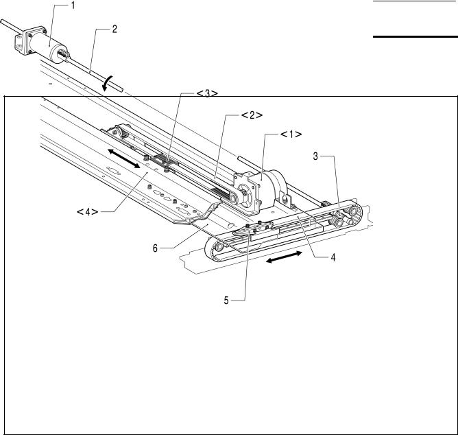
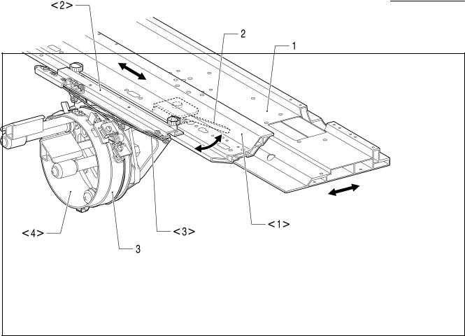
1. Feed guide mechanism
2549M
[X direction] <1>.X-pulse motor <2>.Timing belt <3>.X-driving carriage <4>.X-feed frame
[Y direction] 1.Y-pulse motor
2.Y-driving connecting shaft
3.Y-driving pulley
4.Y-driving belt
5.X-carriage
6.Y-feed frame
BE-1204B-BC • BE-1204C-BC • BE-1206B-BC |
1-1 |
From the library of Superior Sewing Machine & Supply LLC - www.supsew.com

Chapter 1 Mechanical Descriptions
2. Crank shaft mechanism
2550M
1.Motor 2.Timing belt 3.Driving pulley
4.Connecting shaft upper 5A.Cloth presser cam 5B.Thread take-up driving cam 5C.Needle bar driving cam
1-2 |
BE-1204B-BC • BE-1204C-BC • BE-1206B-BC |
From the library of Superior Sewing Machine & Supply LLC - www.supsew.com
Chapter 1 Mechanical Descriptions
3.Presser foot mechanism
2551M
1.Driving pulley 2.Connecting shaft upper 3.Presser foot cam
4.Work clamp driving lever assy 5.Driving connector
6.W-clamp lifting parts 7.Work clamp bracket 8.Presser foot
BE-1204B-BC • BE-1204C-BC • BE-1206B-BC |
1-3 |
From the library of Superior Sewing Machine & Supply LLC - www.supsew.com

Chapter 1 Mechanical Descriptions
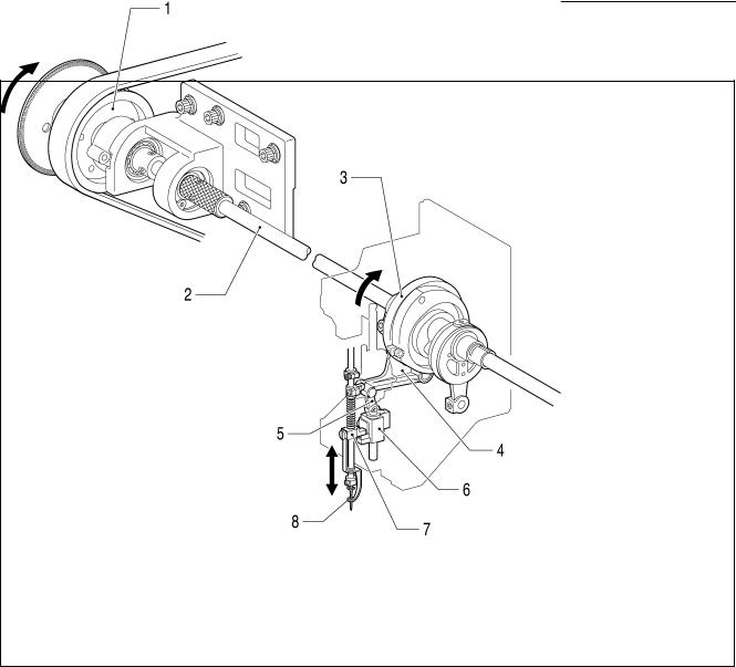
4.Thread take-up mechanism
2552M
1.Driving pulley 2.Connecting shaft upper 3.Thread take-up driving cam 4.Thread take-up driving lever 5.Lever
6.Thread take-up lever
1-4 |
BE-1204B-BC • BE-1204C-BC • BE-1206B-BC |
From the library of Superior Sewing Machine & Supply LLC - www.supsew.com
Chapter 1 Mechanical Descriptions
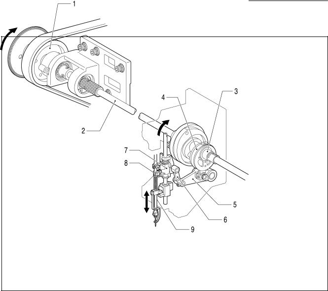
5. Needle bar mechanism
2553M
1.Driving pulley 2.Connecting shaft upper 3.Needle bar driving cam 4.Connecting rod 5.Needle bar driving lever 6.Driving connector 7.Needle bar lifting parts 8.Needle bar clamp 9.Needle bar
BE-1204B-BC • BE-1204C-BC • BE-1206B-BC |
1-5 |
From the library of Superior Sewing Machine & Supply LLC - www.supsew.com
Chapter 1 Mechanical Descriptions
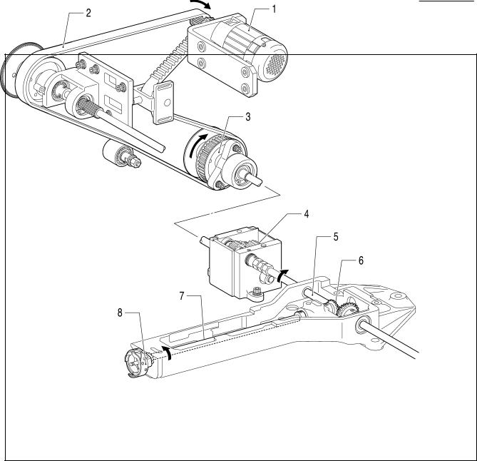
6.Lower shaft and rotary hook mechanisms
2554M
1.Motor 2.Timing belt 3.Driving pulley 4.Gear
5.Driving shaft lower 6.Lower shaft gear 7.Lower shaft 8.Rotary hook
1-6 |
BE-1204B-BC • BE-1204C-BC • BE-1206B-BC |
From the library of Superior Sewing Machine & Supply LLC - www.supsew.com

Chapter 1 Mechanical Descriptions
7.Thread trimmer mechanism
2555M
1.Thread trimmer motor 2.Thread trimmer gear 3.Driving lever 4.Connedtion shaft
5.T-trimmer connecting rod lever
6.T-trimmer connecting rod, B
7.T-trimmer con. rod assy, A 8.Movable knife
BE-1204B-BC • BE-1204C-BC • BE-1206B-BC |
1-7 |
From the library of Superior Sewing Machine & Supply LLC - www.supsew.com

Chapter 1 Mechanical Descriptions
8.Thread wiper mechanism
2556M
1.Wiper motor bracket 2.Wiper lever 3.Upper thread hook
1-8 |
BE-1204B-BC • BE-1204C-BC • BE-1206B-BC |
From the library of Superior Sewing Machine & Supply LLC - www.supsew.com
Chapter 1 Mechanical Descriptions
9.Picker mechanism
2557M
1.Picker solenoid 2.Picker lever 3.Picker base 4.Picker
BE-1204B-BC • BE-1204C-BC • BE-1206B-BC |
1-9 |
From the library of Superior Sewing Machine & Supply LLC - www.supsew.com
Chapter 1 Mechanical Descriptions
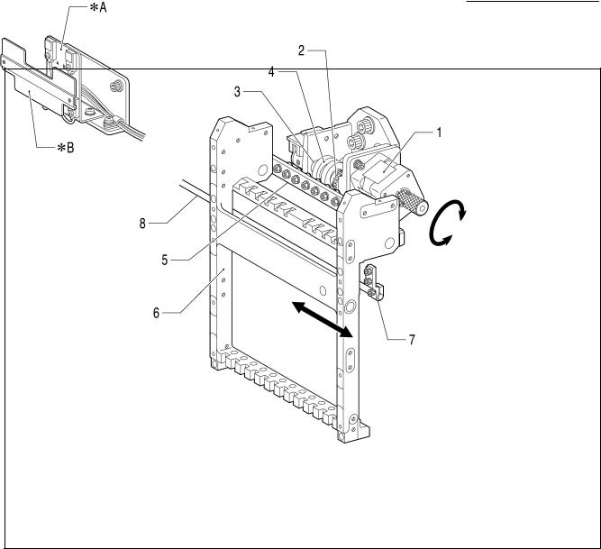
10.Needle bar flip-up mechanism
2558M
1.Change color motor 2.Change color gear 3.Shaft
4.Change cam 5.Change roller base 6.Needle bar case 7.Change bracket collar 8.Connection shaft
*A |
Change color sensor |
*B |
Dog |
1-10 |
BE-1204B-BC • BE-1204C-BC • BE-1206B-BC |
From the library of Superior Sewing Machine & Supply LLC - www.supsew.com
Chapter 1 Mechanical Descriptions
11.Cap frame device
2559M
[X direction] <1>.X-feed frame <2>.Cap frame <3>.Wire <4>.Driving ring
[Y direction] 1.Y-feed frame 2.Fixing lever 3.Driving ring
BE-1204B-BC • BE-1204C-BC • BE-1206B-BC |
1-11 |
From the library of Superior Sewing Machine & Supply LLC - www.supsew.com
Chapter 2 Parts replacement and adjustment
Chapter 2 Parts replacement and adjustment
1.Replacement and adjustment of jump driving assy, cloth presser cam, thread take-up driving cam, needle bar driving cam, driving belt and upper shaft sensor
[Removing procedure]
2560M
1.Unscrew the screws of cover lower and upper (1) and cover R (2) to remove them. Unscrew the screws of side cover L (3) to remove it.
Also remove the other covers.
2561M
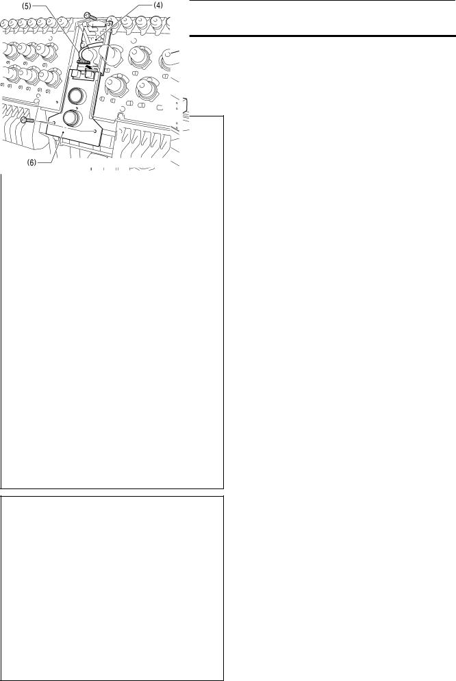
2. Detach the connector of tension base harness (5) from I/O PCB (4).
Unscrew the screws of base (6) to remove it.
2562M
2-1 |
BE-1204B-BC • BE-1204C-BC • BE-1206B-BC |
From the library of Superior Sewing Machine & Supply LLC - www.supsew.com

Chapter 2 Parts replacement and adjustment
3.Take off 4 bolts of thread take-up cover (7) to remove it.
4.Take off 4 bolts of needle bar case (8) to remove it.
2563M
|
|
|
5. Loosen 2 bolts of bearing collar pulley (9), |
|
2564M |
||
|
and also loosen 1 bolt of needle bar cam |
||
|
|
|
|
|
|
|
collar (10) of each head. |
|
|
|
|
2565M
BE-1204B-BC • BE-1204C-BC • BE-1206B-BC |
2-2 |
From the library of Superior Sewing Machine & Supply LLC - www.supsew.com
Chapter 2 Parts replacement and adjustment
2566M
2567M
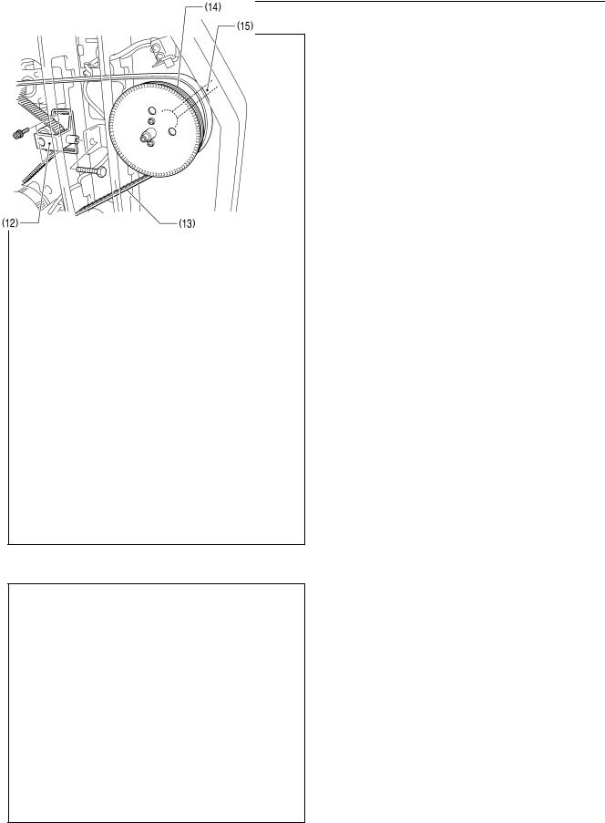
6.Unscrew 1of 2 screws of upper shaft sensor base plate (11), and then loosen the other
one to fasten upper shaft sensor base plate (11) upward temporary.
Take off 3 bolts of tensor pulley holder (12) to remove it.
Detach driving belt (13) from driving pulley (14).
Extract driving shaft upper (15) together with driving pulley (14).
7. To replace driving belt, loosen 2 set screws of tension pulley holder (12) to extract tension shaft (16), and then detach driving belt (13).
2568M
2-3 |
BE-1204B-BC • BE-1204C-BC • BE-1206B-BC |
From the library of Superior Sewing Machine & Supply LLC - www.supsew.com

Chapter 2 Parts replacement and adjustment
8.Unscrew 2 screws each of front cover R (17) and front cover L (18) to remove both of them.
2569M
9.Take off 2 bolts of jump driving assy (19) to remove it.
Take off 2 bolts of wiper driving assy (20) to remove it.
2570M
10.Remove the base needle bar felt (21-1) and loosen a set screw, socket to pull out the base needle bar (21).
2571M
BE-1204B-BC • BE-1204C-BC • BE-1206B-BC |
2-4 |
From the library of Superior Sewing Machine & Supply LLC - www.supsew.com
Chapter 2 Parts replacement and adjustment
11. Unscrew 2 screws of oil support A (22) to remove it.
Loosen 3 set screws of driving lever shaft (23) to extract it.
Loosen 1 bolt of needle bar cam collar (24) to remove it.
Now needle bar cam (25) can be detached.
2572M
12. Loosen 1 bolt of cloth presser cam collar
(26) to remove it.
Loosen 2 bolts of cloth presser cam (27) to remove it.
To mount cloth presser cam collar (26), insert positioning gauge pin (28) into the positioning hole on the cam and fasten 1 bolt.
Grease the groove of cloth presser cam (27) indicated by the arrow in the drawing.
CAUTION
Use the positioning gauge pin included in the attachment of the sawing machine.
Use the attached grease tank EM-30L for the greasing.
2573M
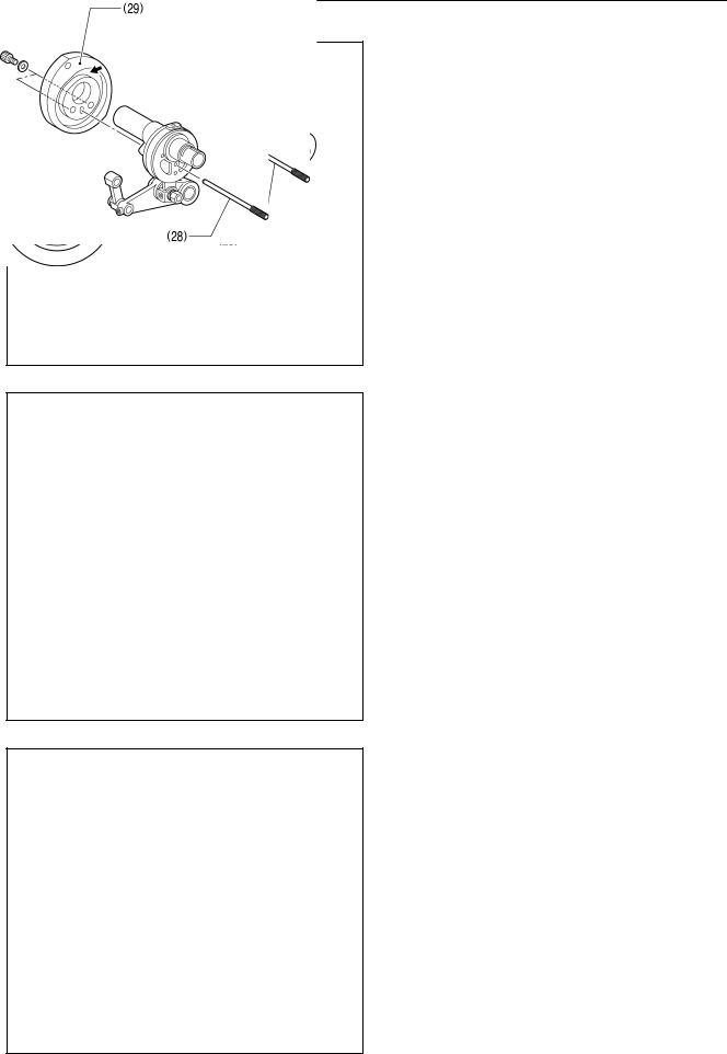
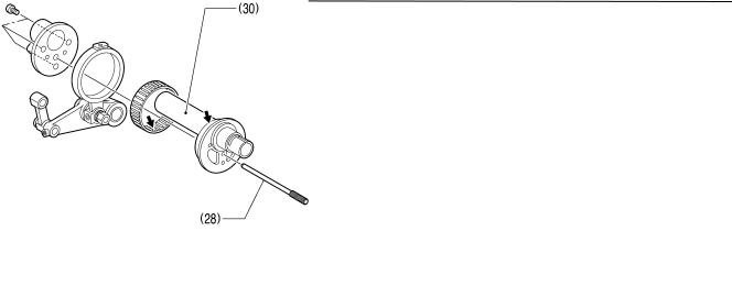
13. Take off 2 bolts of thread take-up driving cam (29) to remove it.
To mount thread take-up driving cam (29), insert positioning gauge pin (28) into the positioning hole on the cam and fasten 2 bolts.
Grease the groove of thread take-up driving cam (29) indicated by the arrow in the drawing.
CAUTION
Use the positioning gauge pin included in the attachment of the sawing machine.
Use the attached grease tank EM-30L for the greasing.
2574M
2-5 |
BE-1204B-BC • BE-1204C-BC • BE-1206B-BC |
From the library of Superior Sewing Machine & Supply LLC - www.supsew.com
Chapter 2 Parts replacement and adjustment
|
|
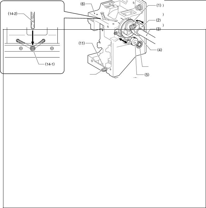
14. Unscrew 2 screws of needle bar driving cam |
|
|
|
|
|
(30) to remove it. |
|
|
Grease needle bar driving cam (30) at the |
|
|
position indicated by the arrow in the |
|
|
drawing. |
|
|
To mount needle bar driving cam (30), insert |
|
|
positioning gauge pin (28) into the |
|
|
positioning hole on the cam and fasten 2 |
|
|
screws. |
|
|
CAUTION |
|
|
Use the positioning gauge pin included in |
|
|
the attachment of the sawing machine. |
|
2575M |
Use the attached grease tank EM-30L for |
|
the greasing. |
|
|
|
BE-1204B-BC • BE-1204C-BC • BE-1206B-BC |
2-6 |
From the library of Superior Sewing Machine & Supply LLC - www.supsew.com
Chapter 2 Parts replacement and adjustment
[Mounting procedure]
To mount pieces, follow the reverse procedure to the disassembly. The followings are the key points in the mounting.
2576M
LIQUID GASKET
LIQUID GASKET
2577M
1.Grease the connecting shaft upper on spots that touches bearings of the driving pulley, driving shaft support or each head.
2.Attach needle bar cam collar (2) to needle bar driving cam (1), insert driving shaft upper (3) and fasten the bolt (4) temporary so that needle bar driving cam (1) rotates easily.
3.Insert driving lever shaft (5) into head (6), work clamp driving lever (7), spacer (8), needle bar driving lever (9) and set screw collar (10), then fasten 3 set screws.
4.Spread a sealing agent on the left side of head (6) and lever shaft (5) to prevent oil leak.
5.Insert base needle bar (11) into head (6), work clamp lifting parts (12), and needle bar lifting parts (13), and fasten 1 set screw (14).
6.Reset the wick (14-1) so that it touches the base needle bar felt (14-2).
7.Spread a sealing agent on the bottom faces of head (6) and base needle bar (11) to prevent oil leak.
CAUTION
Rotate needle bar cam collar (2) and see if needle bar driving cam (1) rotates easily. If not, loosen 1 set screw (15) of driving lever shaft (5) to shift it toward the thrust for adjustment.
2-7 |
BE-1204B-BC • BE-1204C-BC • BE-1206B-BC |
From the library of Superior Sewing Machine & Supply LLC - www.supsew.com
 Loading...