


BE-1204B-BC BE-1206B-BC
INSTRUCTION MANUAL
Stand-Alone type
Please read this manual before using the machine.
Please keep this manual within easy reach for quick reference.
TWELVE NEEDLE FOUR HEAD EMBROIDERY MACHINE TWELVE NEEDLE SIX HEAD EMBROIDERY MACHINE

Thank you very much for buying a BROTHER sewing machine. Before using your new machine, please read the safety instructions below and the explanations given in the instruction manual.
With industrial sewing machines, it is normal to carry out work while positioned directly in front of moving parts such as the needle and thread take-up lever, and consequently there is always a danger of injury that can be caused by these parts. Follow the instructions from training personnel and instructors regarding safe and correct operation before operating the machine so that you will know how to use it correctly.
SAFETY INSTRUCTIONS
1 Safety indications and their meanings
This instruction manual and the indications and symbols that are used on the machine itself are provided in order to ensure safe operation of this machine and to prevent accidents and injury to yourself or other people. The meanings of these indications and symbols are given below.
Indications
DANGER |
The instructions which follow this term indicate situations where failure to |
|
follow the instructions will almost certainly result in death or severe injury. |
||
|
|
|
CAUTION |
The instructions which follow this term indicate situations where failure to |
|
follow the instructions could cause injury when using the machine or physical |
||
|
damage to equipment and surroundings. |
|
Symbols |
|
|
-------- This symbol ( |
) indicates something that you should be careful of. |
|
The picture inside the triangle indicates the nature of the caution that must be taken. (For example, the symbol at left means "beware of injury".)
 --------- This symbol (
  ) indicates something that you must not do.
--------- This symbol ( ) indicates something that you must do.
The picture inside the circle indicates the nature of the thing that must be done. (For example, the symbol at left means "you must make the ground connection".)
BE-1204B-BC • BE-1206B-BC |
1 |

2 Notes on safety
 DANGER
Wait at least 5 minutes after turning off the power switch and disconnecting the power cord from the wall outlet before opening the face plate of the control box. Touching areas where high voltages are present can result in severe injury.
 CAUTION
Environmental requirements
Use the sewing machine in an area which is free from sources of strong electrical noise such as high-frequency welders.
Sources of strong electrical noise may cause problems with correct operation.
Any fluctuations in the power supply voltage should be within ±10% of the rated voltage for the machine.
Voltage fluctuations which are greater than this may cause problems with correct operation.
The power supply capacity should be greater than the requirements for the sewing machine's electrical consumption. Insufficient power supply capacity may cause problems with correct operation.
The air supply should have a capacity greater than the machine consumption. If air is not supplied sufficiently, a machine malfunction may occur.
The ambient temperature should be within the range of 5°C to 35°C during use.
Temperatures which are lower or higher than this may cause problems with correct operation.
The relative humidity should be within the range of 45% to 85% during use, and no dew formation should occur in any devices.
Excessively dry or humid environments and dew formation may cause problems with correct operation.
Avoid exposure to direct sunlight during use. Exposure to direct sunlight may cause problems with correct operation.
In the event of an electrical storm, turn off the power and disconnect the power cord from the wall outlet.
Lightning may cause problems with correct operation.
Do not use this machine outdoors.
Installation
Machine installation should only be carried |
Be sure to connect the ground. If the ground |
|
out by a qualified technician. |
connection is not secure, you run a high risk of |
|
Never operate the sewing machine with any |
receiving a serious electric shock, and problems |
|
with correct operation may also occur. |
||
ventilation openings blocked. |
When securing the cords, do not bend the cords |
|
Keep the ventilation openings of the sewing |
||
excessively or fasten them too hard with staples, |
||
machine free from the accumulation of lint or |
otherwise there is the danger that fire or electric |
|
dust. |
shocks could occur. |
|
Contact your Brother dealer or a qualified |
Be sure to wear protective goggles and gloves |
|
electrician for any electrical work that may |
when handling the lubricating oil or grease, so that |
|
need to be done. |
no oil or grease gets into your eyes or onto your |
|
The sewing machine weights more than 700 |
skin, otherwise inflammation can result. |
|
Furthermore, do not drink the oil or grease under |
||
Kg (600 Kg in four head models). |
any circumstances, as they can cause vomiting |
|
The installation should be carried out by four |
and diarrhoea. |
|
or more people. |
Keep the oil out of the reach of children. |
|
Do not connect the power cord until |
Secure the machine with the adjustment bolts on |
|
installation is complete, otherwise the |
the sound floor so that it will not move. |
|
machine may operate if the start switch is |
|
|
pressed by mistake, which could result in |
|
|
injury. |
|
2 |
BE-1204B-BC • BE-1206B-BC |

Installation
Avoid setting up the sewing machine near sources of strong electrical noise such as high-frequency welding equipment.
If this precaution is not taken, incorrect machine operation may result.
 CAUTION
Sewing
This sewing machine should only be used by operators who have received the necessary training in safe use beforehand.
Keep children away from the sewing machine.
The sewing machine should not be used for any applications other than sewing.
Be sure to wear protective goggles when using the machine.
If goggles are not worn, there is the danger that if a needle breaks, parts of the broken needle may enter your eyes and injury may result.
Always use the proper needle plate. Any wrong plate can cause needles to break.
Do not use a bent needle.
Turn off the power switch at the following times, otherwise the machine may operate if the start switch is pressed by mistake, which could result in injury.
•When threading the needle
•When replacing the bobbin and needle
•When not using the machine and when leaving the machine unattended
•When cleaning the machine.
Do not get on the table.
Table may be damaged.
Do not operate this machine where aerosol (spray) products are being used or where oxygen is being administered.
Attach all safety devices before using the sewing machine. If the machine is used without these devices attached, injury may result.
Do not touch any moving parts, press any objects against the machine, or pull/push the cloth during sewing. Doing so may result in personal injury, machine damage, or needle breakage.
Do not touch the pulse motor and sewing machine bed section during operation or for 30 minutes after operation. Otherwise burns may result.
Never drop or insert foreign objects or a screwdriver into the ventilation openings or the machine inside.
Touching any high-voltage area may result in an electric shock.
Never damage, alter, heat, or put a strain on the power cable as well as other cables. Doing so may result in a fire or an electric shock.
If the controller is exposed to water or a chemical agent or if its entry is found inside the controller, turn off the power switch immediately. Continuing to use the machine under such a condition may result in a fire or an electric shock.
If an error occurs in machine operation, or if abnormal noises or smells are noticed, immediately turn off the power switch. Then contact your nearest Brother dealer or a qualified technician.
If the machine develops a problem, contact your nearest Brother dealer or a qualified technician.
Cleaning
Turn off the power switch before starting any cleaning work, otherwise the machine may operate if the start switch is pressed by mistake, which could result in injury.
Be sure to wear protective goggles and gloves when handling the lubricating oil or grease, so that no oil or grease gets into your eyes or onto your skin, otherwise inflammation can result. Furthermore, do not drink the oil or grease under any circumstances, as they can cause vomiting and diarrhoea.
Keep the oil out of the reach of children.
BE-1204B-BC • BE-1206B-BC |
3 |

Maintenance and inspection
Maintenance and inspection of the sewing |
If the power switch needs to be left on when |
|
machine should only be carried out by a |
carrying out some adjustment, be extremely |
|
qualified technician. |
careful to observe all safety precautions. |
|
Ask your Brother dealer or a qualified |
Use only the proper replacement parts as |
|
electrician to carry out any maintenance and |
specified by Brother. |
|
inspection of the electrical system. |
When replacing a fluorescent lamp, use the |
|
Turn off the power switch and disconnect the |
same-type lamp having a rating of 40 watts. |
|
Wait until the fluorescent lamp cools off before |
||
power cable (do not pull on the cable itself) |
replacement. Failure to do so can result in |
|
from the wall outlet before attempting to |
burns. |
|
perform the following operations. Otherwise, |
If any safety devices have been removed, be |
|
the machine is started if the start switch is |
||
pressed by mistake. Injury may occur in |
absolutely sure to re-install them to their original |
|
such a case. |
positions and check that they operate correctly |
|
• When carrying out inspection, adjustment, |
before using the machine. |
|
or maintenance |
Any problems in machine operation which result |
|
• When replacing consumable parts such |
||
from unauthorized modifications to the machine |
||
as a rotary hook, a knife, or a fluorescent |
will not be covered by the warranty. |
|
lamp |
|
4 |
BE-1204B-BC • BE-1206B-BC |

3 Warning labels
* The following warning labels appear on the sewing machine.
Please follow the instructions on the labels at all times when using the machine. If the labels have been removed or are difficult to read, please contact your nearest Brother dealer.
1 Electric shock danger display
|
W1408Q |
2 Electric shock danger display |
3 Injury warning display |
Hazardous voltage |
will |
cause injury. |
|
W1410Q
4Injury caution display
W1200Q
5Injury caution display
W1202Q
BE-1204B-BC • BE-1206B-BC |
5 |
6 |
Injury caution display |
7 Injury caution display |
|
Never touch or push the thread take up during operation as it may result in injuries machine.
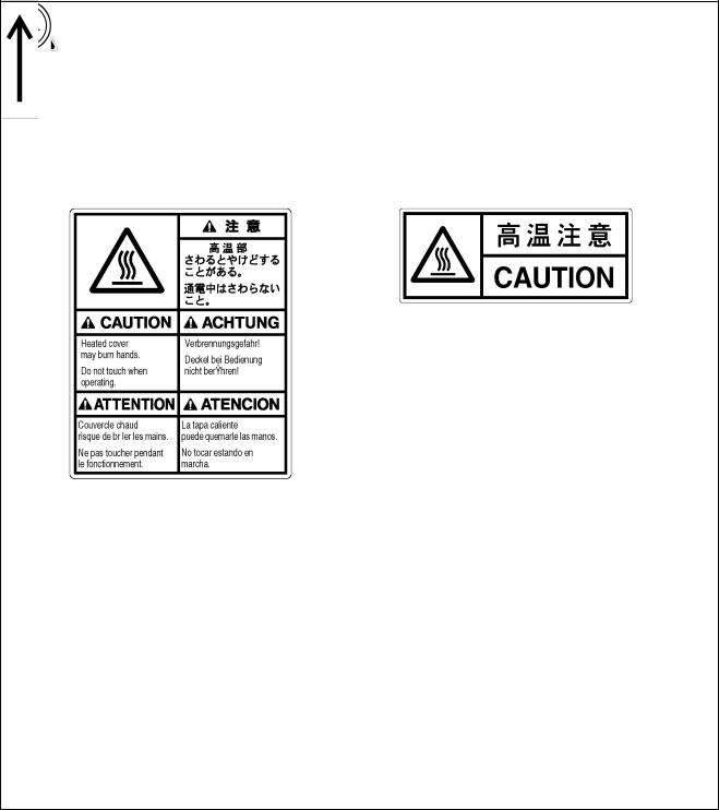
8High temperature caution display
Never touch or push the needle bar during operation as it may result in injuries or damage to the sewing machine.
9High temperature caution display
W1206Q
Do not touch this part during activitation or for 30 minutes after shut-off. Otherwise burns may result.
W1201Q
10 Ground mark
Be sure to connect the ground. If the ground connection is not secure, you run a high risk of receiving a serious electric shock, and problems with correct operation may also occur.
11 Direction of operation
W1205Q
6 |
BE-1204B-BC • BE-1206B-BC |

6
7
5
4
5
2
10
1
W1207Q
9
8
8 |
8 |
4
3
11
4
4
W1208Q
BE-1204B-BC • BE-1206B-BC |
7 |
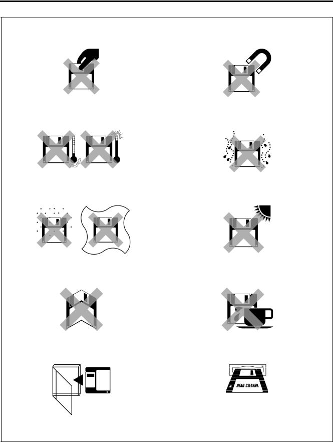
Before Starting Operation
Do not force open the shutter for direct contact with the magnetic area.
Do not bring disks near magnetic matters such as magnetic screwdriver or the back side of the programmer.
W1209Q |
W1210Q |
|
Do not store floppy disks in an extremely high or low ambient temperature.
Do not use floppy disks under high humidity.
W1211Q
W1212Q
Do not use or store floppy disks in a dusty place. Do not place it on cloth.
Do not store floppy disks under direct sunlight.
W1213Q |
W1214Q |
Do not bend the disk. Do not put things on the disk.
Avoid contact with solvent or drink.
W1215Q |
W1216Q |
Store it in the case immediately after using it to protect it from dust and damage.
Use a commercially available cleaning disk to clean the head of the floppy disk drive periodically.
W1218Q
W1217Q
Do not remove the disk out of the drive during the access lamp is lit.
8 |
BE-1204B-BC • BE-1206B-BC |
Protecting data in floppy disks
Write-protection is available for a floppy disk to prevent undesired data deletion.
A write-protected disk is read-only. It is recommended to provide write-protection for disks which contain important data.
To do so, slide the write-protect notch to open the slot as shown below.
Slide the notch in this direction to prevent data loss or overwriting.
Slide the notch in this direction to write data.
W1219Q
BE-1204B-BC • BE-1206B-BC |
9 |

Procedure of Reading This Manual
Explanation of models
This manual explains two models:
-BE-1204B-BC
-BE-1206B-BC
Explanation for individual model is provided by identifying the model name. Check the model before using the machine. The display is BE-1206B-BC.
Configuration of this manual
This manual consists of the following chapters:
Chapter 1 Preparation of Embroidery Machine
This Chapter describes the specifications, installation and preparatory procedures of starting up the machine.
Chapter 2 Embroidering Procedures
Provides explanations on the operation panel and briefly reviews the flow of embroidering processes.
Chapter 3 Selection of Data and Embroidering
This Chapter describes procedures of reading sewing data and sewing.
Chapter 4 Editing of Embroidering Data
Explains how to edit the embroidery data.
Chapter 5 |
Setting |
This Chapter describes procedures of setting the machine and working environment.
Chapter 6 Operation of Machine
Provides information on machine operation during embroidering.
Chapter 7 |
Maintenance |
Describes appropriate maintenance of the machine.
Chapter 8 |
Adjustment |
Explains how to adjust the needles.
Chapter 9 List of Error Messages
Provides information on error codes and action to be taken.
Chapter 10 Troubleshooting
Provides troubleshooting for the machine.
Chapter 11 Connection and Installation of Optional Equipment
Describes connections between the machine/computer and optional equipment available.
10 |
BE-1204B-BC • BE-1206B-BC |
BE-1204B-BC • BE-1206B-BC |
11 |

Screen Composition
Initial Screen
W0406Q
Starting Sewing Operation (→ page 3-17)
Canceling of Sewing
Thread trimming
Hoop Retract
Area Check
Selection of Embroidery data (→ page 3-3)
W0397Q
Setting of Needle Bars
(→ page 5-4)
W0481Q
Editing of Embroidery data (→ page 4-1)
W0451Q
W0465Q
W0601Q
12 |
BE-1204B-BC • BE-1206B-BC |

Setting of thread breakage sensor (→ page 5-6)
W0488Q
W0490Q
W0494Q
Setting of Machine (→ page 5-9)
W0609Q
W0620Q
W0621Q
BE-1204B-BC • BE-1206B-BC |
13 |

Contents
Contents
SAFETY INSTRUCTIONS................................................................................................................................................. |
1 |
Before Starting Operation............................................................................................................................................... |
8 |
Procedure of Reading This Manual.............................................................................................................................. |
10 |
Screen Composition...................................................................................................................................................... |
12 |
Chapter 1 Preparation of Embroidery Machine
1. Specifications ........................................................................................................................................................... |
1-2 |
|
2. Names of Machine Components ............................................................................................................................. |
1-4 |
|
3. Installation................................................................................................................................................................. |
1-5 |
|
3-1 Transportation of Machine ................................................................................................................................. |
1-5 |
|
3-2 Installation of Machine....................................................................................................................................... |
1-7 |
|
3-3 Preparation of Needle Bar Case........................................................................................................................ |
1-8 |
|
3-4 Mounting of Table .............................................................................................................................................. |
1-9 |
|
3-5 Mounting of Cotton Stand ................................................................................................................................ |
1-12 |
|
3-6 Lubrication to Needle Bar Case....................................................................................................................... |
1-13 |
|
3-7 |
Grounding........................................................................................................................................................ |
1-14 |
4. Preparation for Embroidering................................................................................................................................ |
1-15 |
|
4-1 |
Upper Threading.............................................................................................................................................. |
1-15 |
4-2 |
Replacement of Bobbin ................................................................................................................................... |
1-17 |
4-3 |
Replacing and Selecting Needle...................................................................................................................... |
1-19 |
4-4 Attachment of Embroidery Hoop and Frame ................................................................................................... |
1-20 |
|
4-5 Adjustment of Thread Tension ......................................................................................................................... |
1-24 |
|
Chapter 2 Embroidering Procedures
Functions of Operation Panel...................................................................................................................................... |
2-2 |
Operation Panel....................................................................................................................................................... |
2-2 |
Switches at Machine Heads .................................................................................................................................... |
2-5 |
Lamps and switches on the thread tension stand .................................................................................................... |
2-6 |
Flowchart of Preparation for Embroidering ............................................................................................................... |
2-7 |
Turn on the Machine Power..................................................................................................................................... |
2-8 |
Retrieve the Embroidery Data ................................................................................................................................. |
2-9 |
Start Embroidering................................................................................................................................................... |
2-9 |
Chapter 3 Selection of Data and Embroidering
What Can the Machine Do? ......................................................................................................................................... |
3-2 |
Selection of Embroidery Data....................................................................................................................... |
3-2 |
Embroidering Operation........................................................................................................................................... |
3-2 |
Selection of Data .......................................................................................................................................................... |
3-3 |
Registration of Embroidery Data from Floppy Disk .................................................................................................. |
3-3 |
Reading from Memory ............................................................................................................................................. |
3-7 |
Registration of Embroidery Data from BES-100E.................................................................................................... |
3-8 |
Deletion of Embroidery Data from Machine Memory ............................................................................................... |
3-9 |
Tape Reader Input Setting ......................................................................................................................................... |
3-11 |
Modification of Embroidery Data Name.................................................................................................................... |
3-13 |
Sewing Operation....................................................................................................................................................... |
3-17 |
Before Starting Sewing .......................................................................................................................................... |
3-17 |
Starting Sewing Operation ..................................................................................................................................... |
3-17 |
Feedhold and Cancellation of Sewing ................................................................................................................... |
3-18 |
Step Forward and Step-Back..................................................................................................................................... |
3-19 |
Step Forward/Step-Back Mode .............................................................................................................................. |
3-19 |
Setting Amount or Timing of Step Forward/Step-Back ........................................................................................... |
3-19 |
14 |
BE-1204B-BC • BE-1206B-BC |

Contents
For Step Forward (Back) ........................................................................................................................................ |
3-20 |
Resuming Sewing .................................................................................................................................................. |
3-20 |
Writing the embroidering data ................................................................................................................................... |
3-21 |
Chapter 4 Editing of Embroidering Data
What Can the Machine Do?.......................................................................................................................................... |
4-2 |
Editing............................................................................................................................................................. |
4-2 |
Rotation ......................................................................................................................................................................... |
4-3 |
Enlargement and Reduction ........................................................................................................................................ |
4-4 |
Mirror ............................................................................................................................................................................. |
4-6 |
Repetition ...................................................................................................................................................................... |
4-8 |
Other Editing ............................................................................................................................................................... |
4-10 |
Chapter 5 Setting
What Can the Machine Do?.......................................................................................................................................... |
5-2 |
Setting of Needle Bars.................................................................................................................................. |
5-2 |
Setting of Thread Breakage Sensor ............................................................................................................. |
5-2 |
Setting of Machine........................................................................................................................................ |
5-2 |
Setting of Environment ................................................................................................................................. |
5-2 |
Setting of Lock Stitch ...................................................................................................................................... |
5-3 |
Setting of speed limit in a small pitch .............................................................................................................. |
5-3 |
Display of Information................................................................................................................................... |
5-3 |
Hoop Retract Point ....................................................................................................................................... |
5-3 |
Hoop Movement....................................................................................................................................................... |
5-3 |
Setting of Needle Bars.................................................................................................................................................. |
5-4 |
Thread Breakage Sensor.............................................................................................................................................. |
5-6 |
Setting of sensor validity/invalidity............................................................................................................................ |
5-6 |
Thread Breakage Sensitivity .................................................................................................................................... |
5-6 |
Automatic Step-Back................................................................................................................................................ |
5-7 |
Setting of Lower Thread Counter/Stitch Counter...................................................................................................... |
5-8 |
Setting of Machine ........................................................................................................................................................ |
5-9 |
Embroidery Hoop ..................................................................................................................................................... |
5-9 |
Speed Range ......................................................................................................................................................... |
5-10 |
Speed of Each Speed Range ................................................................................................................................. |
5-11 |
Setting of Mending ................................................................................................................................................. |
5-12 |
Thread Trimming Length ........................................................................................................................................ |
5-14 |
Thread Withdrawal Feed Length............................................................................................................................ |
5-15 |
Inching ................................................................................................................................................................... |
5-16 |
Sewing Area........................................................................................................................................................... |
5-17 |
Registration of Sewing Start Position ..................................................................................................................... |
5-18 |
Hoop Retract Point................................................................................................................................................. |
5-18 |
Hoop Automatic Retract ......................................................................................................................................... |
5-19 |
Movement to Registered Sewing Start Point.......................................................................................................... |
5-19 |
Setting of Environment .............................................................................................................................................. |
5-20 |
Return to Start Point............................................................................................................................................... |
5-20 |
Speed Range ......................................................................................................................................................... |
5-21 |
Checking the Embroidery Area .............................................................................................................................. |
5-21 |
Slow sewing needle number at start-up ................................................................................................................. |
5-22 |
Setting of RS-232C Communication Speed ........................................................................................................... |
5-23 |
Display Language .................................................................................................................................................. |
5-24 |
Alarm Sound .......................................................................................................................................................... |
5-25 |
Motive Speed ......................................................................................................................................................... |
5-26 |
Small-Pitch Deletion............................................................................................................................................... |
5-27 |
Automatic pause insertion...................................................................................................................................... |
5-28 |
BE-1204B-BC • BE-1206B-BC |
15 |

Contents
Lock Stitch ............................................................................................................................................................. |
5-29 |
Speed Limit in a Short Pitch................................................................................................................................... |
5-32 |
Feed Timing........................................................................................................................................................... |
5-33 |
Automatic Input Setting.......................................................................................................................................... |
5-34 |
Display of Information................................................................................................................................................ |
5-37 |
Pattern Information ................................................................................................................................................ |
5-37 |
Features of Machine.............................................................................................................................................. |
5-38 |
Information about Versions .................................................................................................................................... |
5-39 |
Chapter 6 Operation of Machine
1. |
Operating Procedures.............................................................................................................................................. |
6-2 |
|
1-1 Power Source.................................................................................................................................................... |
6-2 |
|
1-2 Preparation for Embroidering............................................................................................................................. |
6-2 |
2. |
Machine Stop ............................................................................................................................................................ |
6-3 |
|
2-1 Stopping the Machine ........................................................................................................................................ |
6-3 |
|
2-2 Emergency Stop of the Machine........................................................................................................................ |
6-3 |
|
2-3 Resetting Emergency Stop ................................................................................................................................ |
6-3 |
3. |
Measures against Thread Breakage ....................................................................................................................... |
6-4 |
|
3-1 Remedies .......................................................................................................................................................... |
6-4 |
|
3-2 Mending............................................................................................................................................................. |
6-5 |
4. |
Jog Embroidering..................................................................................................................................................... |
6-7 |
5. |
Hoop Feed Position.................................................................................................................................................. |
6-8 |
6. Area Check................................................................................................................................................................ |
6-9 |
|
|
6-1 External Tracing................................................................................................................................................. |
6-9 |
|
6-2 Automatic Hoop Movement in Area ................................................................................................................... |
6-9 |
7. |
Jog Switches........................................................................................................................................................... |
6-10 |
|
7-1 Hoop Movement to Start Position .................................................................................................................... |
6-10 |
|
7-2 Inching Mode during Embroidering (Forcible Hoop Movement) ...................................................................... |
6-11 |
8. |
Detection of Home position................................................................................................................................... |
6-12 |
Chapter 7 |
Maintenance |
|
|
1. |
Cleaning .................................................................................................................................................................... |
7-2 |
|
|
1-1 Cleaning and Lubrication of Rotary Hook .......................................................................................................... |
7-2 |
|
|
1-2 Cleaning of Needle Plate................................................................................................................................... |
7-3 |
|
2. |
Oiling ......................................................................................................................................................................... |
7-4 |
|
|
2-1 Head.................................................................................................................................................................. |
7-4 |
|
|
2-2 Lower shaft........................................................................................................................................................ |
7-5 |
|
3. |
Greasing.................................................................................................................................................................... |
7-6 |
|
|
3-1 Cam grooves ..................................................................................................................................................... |
7-6 |
|
|
3-2 Lower gear ........................................................................................................................................................ |
7-8 |
|
|
3-3 |
Diving shaft........................................................................................................................................................ |
7-8 |
|
3-4 |
Needle bar flip-up mechanism........................................................................................................................... |
7-9 |
|
3-5 |
Feed Guide Section......................................................................................................................................... |
7-10 |
16 |
BE-1204B-BC • BE-1206B-BC |

Contents
Chapter 8 |
Adjustment |
|
1. Adjusting Needle Bar Height.................................................................................................................................... |
8-2 |
|
2. Attachment and Adjustment of Rotary Hook .......................................................................................................... |
8-6 |
|
3. Adjustment of Presser Foot Height ......................................................................................................................... |
8-8 |
|
4. Adjustment of Thread Trimmer................................................................................................................................ |
8-9 |
|
4-1 Attaching the Fixed Knife ................................................................................................................................... |
8-9 |
|
4-2 Checking the Movable Knife Position................................................................................................................. |
8-9 |
|
5. Thread Wiper Adjustment ...................................................................................................................................... |
8-12 |
|
Chapter 9 |
Error code list |
|
Chapter 10 Troubleshooting
Mechanical Section..................................................................................................................................................... |
10-2 |
Electrical Section ........................................................................................................................................................ |
10-4 |
Chapter 11 Connection and Installation of Optional Equipment
1. Attaching Bobbin Winder ....................................................................................................................................... |
11-2 |
BE-1204B-BC • BE-1206B-BC |
17 |

Contents
18 |
BE-1204B-BC • BE-1206B-BC |
Chapter 1
Preparation of Embroidery Machine

Chapter 1 Preparations of operation
1. Specifications
Embroidery machine used |
12 needle six-head embroidery |
|
12 needle four-head embroidery |
|
machine |
|
machine |
||
|
|
|||
Application |
Pattern embroidery |
|
|
|
Sewing speed |
Maximum 1000 rpm |
|
|
|
Distance between heads |
360 mm |
|
|
|
|
|
|
|
|
Maximum feed range |
450 (V) × 360 (H) mm |
|
|
|
95 (V) × 360 (H) mm (With cap frame) |
|
|
||
|
|
|
||
|
450 (V) × 360 (H) mm (With sash frame) |
|||
Sewing area |
430 (V) × 300 (H) mm (With maximum-size tubular square hoop/flat hoop) |
|||
|
85 (V) × 360 (H) mm (With cap frame) |
|
|
|
Feed system |
By timing belt and stepping motor drive |
|||
|
|
|||
Stitch length |
0.1 ~ 12.7 mm (minimum pitch: 0.1 mm) |
|||
|
3.5 2DD floppy disk (Tajima format) |
|
|
|
|
3.5 2HD floppy disk (the equivalent to Tajima format) |
|||
Storage medium |
3.5 2DD floppy disk (Barudan FDR/FMC format) |
|||
|
3.5 2DD floppy disk (ZSK format) |
|
|
|
|
3.5 floppy disk (brother ECS format) |
|
|
|
Thread trimming |
Automatic thread trimmer |
|
|
|
Thread breakage detect |
Upper and lower thread breakage detector |
|||
Power supply |
Single phase 200 V, 220 V, 230 V, 240 V,1.7 kVA |
|||
Flourescent lamp: 92VA 49W (Maximum) |
||||
|
||||
Weight |
700 kg |
|
600kg |
|
|
(Before assembly) |
|
(Before assembly) |
|
Dimensions |
3036 (W) × 800 (L) × 1405 (H) mm |
|
2320 (W) × 800 (L) × 1405 (H) mm |
|
(After setup) |
|
(After setup) |
||
|
|
|||
|
3112 (W) × 1345 (L) × 1750 (H) mm |
|
2396 (W) × 1345 (L) × 1750 (H) mm |
|
Options |
Embroidery hoops in different sizes, |
Bobbin winder |
||
|
|
|
|
|
1-2 |
BE-1204B-BC • BE-1206B-BC |

|
|
Chapter 1 Preparations of operation |
Accessories |
|
|
|
|
|
|
Standard Accessories |
Optional Accessories |
|
|
|
Embroidery hoop |
• Tubular square hoop 26 × 43 |
• Holder base 30 × 43 |
|
(6 head: 6, 4 head: 4) |
(6 head: 6, 4 head: 4) |
|
• Tubular round arm set |
Other embroidery hoops in different sizes |
|
(6 head: 7, 4 head: 5) |
• Sash frame assembly |
|
|
|
|
|
* Other Tajima embroidery hoops that can |
|
|
be used with BAS-412A and BES-916AC |
|
|
• Cap frame (6 head: 6, 4 head: 4) |
|
|
Cap frame drive assembly |
|
|
(6 head: 6, 4 head: 4) |
|
|
Base frame set |
|
|
(6 head: 12, 4 head: 8) |
|
|
Set frame base set (1) |
Others |
Table assembly |
• Bobbin winder |
|
|
|
BE-1204B-BC • BE-1206B-BC |
1-3 |
Chapter 1 Preparations of operation
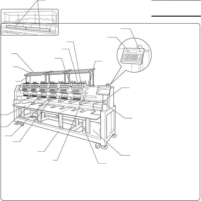
2. Names of Machine Components
Fluorescent lamp switch
Thread tension dial
Thread tension base switch
Thread guide C
STEP BACK /
FWD switch
Thread guide B
Thread guide A
Table
Emergency stop switch
Start switch Stop switch
Leg
Rotary hook cover (Safety device)
Flat / Cap hoop select switch
Operation panel
Cotton stand
Fluorescent lamp switch
Power switch
Control box
Main power switch
W1220Q
The machine heads are numbered 1 to 6 (1 to 4 in four head models) from the right front.
1-4 |
BE-1204B-BC • BE-1206B-BC |
Chapter 1 Preparations of operation
3. Installation
 DANGER
Embroidery machines should be installed only |
Install a machine in a place away from a high- |
by trained engineers. |
frequency welding machine or other machines that |
Electric wiring should be laid by your |
may generate a strong electric noise. Failure to |
do so may cause the embroidery machine to |
|
distributor or electric experts. |
malfunction. |
The sewing machine weights more than |
Be sure to connect the ground. If the ground |
700 Kg (600 Kg in four head models). |
connection is not secure, you run a high risk of |
The installation should be carried out by four |
receiving a serious electric shock, and problems |
or more people. |
with correct operation may also occur. |
Do not connect the power source until |
Secure the machine with the adjustment bolts on |
installation is completed. Doing so may start |
the sound floor so that it will not move. |
the machine unintentionally through an |
|
accidental activation of the START switch, |
|
resulting in bodily injuries. |
|
After installation is completed, get the power supply from a dedicated outlet.
When connecting multiple machines, exercise care not to exceed the capacity of the outlet.
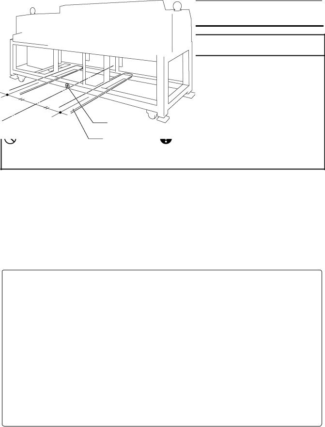
3-1 Transportation of Machine
When relocating the machine, push the steel frame. Never push the cover or carriage.
! When using a fork lift
The central seal
Lift forks
W1222Q
1.Viewing the machine from the back, position their center at the central seal, insert the forks under the legs and lift the machine.
BE-1204B-BC • BE-1206B-BC |
1-5 |
Chapter 1 Preparations of operation
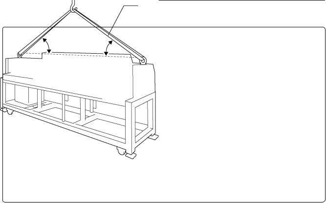
! When using a crane
Belt
More than
45° More than 45°
W1223Q
2.Hook on the eyebolts with each belt to lift up the machine.
When lifting the machine, make sure that the belts do not contact the machine table or the tension plate.
1-6 |
BE-1204B-BC • BE-1206B-BC |

Chapter 1 Preparations of operation
3-2 Installation of Machine
[5]
[1]
[4]
[3]
[2]
W1224Q
1.Place Footboard [4], a rubber cushion 10 [3] (provided with the machine), and PE sheet [2] under each of four adjustment bolts M20 [1]. The Footboard must be on the rubber cushion.
2.Fit four adjustment bolts M20 [1] into the hole of Footboard [4], and adjust the embroidery machine in height.
The adjustment must be made in such a manner that the four bolts are under an equal load when the machine is placed down. (To lower adjustment bolt M20 [1], turn it in the direction of the arrow.) Also, the casters should be raised.
3.After adjusting four adjustment bolts M20 [1], turn nuts M20 [5] in the direction of the arrow to fasten them.
If the floor is not strong enough, the embroidery machine may be rocked during operation. In such a case, it is recommended that a secure base of concrete be placed below the embroidery machine.
BE-1204B-BC • BE-1206B-BC |
1-7 |

Chapter 1 Preparations of operation
3-3 Preparation of Needle Bar Case
[1]
[2]
[3]
W1225Q
Repeat the procedures below for all the heads:
1.Unscrew the screw [1], then detach the bracket [3] and pin [2].
1-8 |
BE-1204B-BC • BE-1206B-BC |
Chapter 1 Preparations of operation
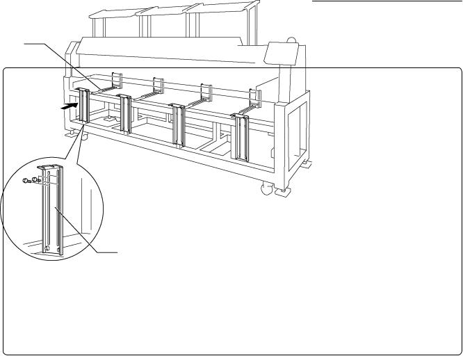
3-4 Mounting of Table
! Preparation for mounting the table
Table guide bridge
[1]
W1226Q
•This operation is required only when the table set is purchased separately from the machine.
•The table is a standard attachment.
1.Tentatively mount 4 (3 in four-head models) table supports Front [1] on the leg front using 4 bolts each.
BE-1204B-BC • BE-1206B-BC |
1-9 |

Chapter 1 Preparations of operation
! For embroidering with tubular square hoop or cap frame (lower position)
[7] |
[6] |
[4]
[6]
[8]
[5]
[3]
[2]
[1] |
[5] |
|
W1227Q
1.Attach four hexagon socket head cap screws to each of table parts R [1], M [2](six head models only), and L [3] from the back.
2.Put the table backing plate [4] of each table on to the table guide bridge [5], and slide to the other side. Insert the table backing plate [4] into the table backing rubber on the table support Rear [6].
3.Adjust table supports front [7] in height so as to make the table parallel with the floor.
4.Tighten all hexagon socket head cap screws [8] firmly.
1-10 |
BE-1204B-BC • BE-1206B-BC |
 Loading...