


 Loading...
BAS-341H BAS-342H
Basic Operation Manual
·
Manual básico de operación
DIRECT DRIVE
PROGRAMMABLE ELECTRONIC PATTERN SEWER
Please read this manual before using the machine.
Please keep this manual within easy reach for quick reference.
*This basic operation manual describes basic operations including sewing machine operations.
For cleaning, standard adjustments and more details, please refer to the instruction manual contained in the download version of the Instruction Manual.
* ·
MOTOR INCORPORADO AL EJE
MÁQUINA ELECTRÓNICA DE ÁREA PROGRAMABLE
Por favor lea este manual antes de usar la máquina.
Por favor guarde este manual al alcance de la mano para una rápida referencia.
*Este manual básico de operación describe las operaciones básicas de la máquina de coser. Para limpiar, realizar ajustes estándar y otros detalles, consulte el manual de instrucciones de la versión de descarga.
BAS-341H, BAS-342H

BAS-341H
BAS-342H
DIRECT DRIVE
PROGRAMMABLE ELECTRONIC PATTERN SEWER
ENGLISH
Thank you very much for buying a BROTHER sewing machine. Before using your new machine, please read the safety instructions below and the explanations given in the instruction manual.
With industrial sewing machines, it is normal to carry out work while positioned directly in front of moving parts such as the needle and thread take-up lever, and consequently there is always a danger of injury that can be caused by these parts. Follow the instructions from training personnel and instructors regarding safe and correct operation before operating the machine so that you will know how to use it correctly.
BAS-341H, BAS-342H

SAFETY INSTRUCTIONS
[1] Safety indications and their meanings
This instruction manual and the indications and symbols that are used on the machine itself are provided in order to ensure safe operation of this machine and to prevent accidents and injury to yourself or other people.
The meanings of these indications and symbols are given below.
Indications
DANGER |
The instructions which follow this term indicate situations where failure to follow the |
instructions will result in death or serious injury. |
|
|
|
WARNING |
The instructions which follow this term indicate situations where failure to follow the |
instructions could result in death or serious injury. |
|
|
|
CAUTION |
The instructions which follow this term indicate situations where failure to follow the |
instructions may result in minor or moderate injury. |
|
|
|
Symbols |
|


This symbol (  ) indicates something that you should be careful of. The picture inside the triangle indicates the nature of the caution that must be taken.
(For example, the symbol at left means “beware of injury”.)
This symbol (  ) indicates something that you must not do.
This symbol (  ) indicates something that you must do. The picture inside the circle indicates the nature of the thing that must be done.
(For example, the symbol at left means “you must make the ground connection”.)
BAS-341H, BAS-342H |
i |

[2] Notes on safety
 DANGER
Wait at least 5 minutes after turning off the power switch and disconnecting the power cord from the wall outlet before opening the control box cover. Touching areas where high voltages are present can result in severe injury.
 WARNING
Do not allow any liquids to get onto this sewing machine, otherwise fire, electric shocks or operating problems may occur.
If any liquid gets inside the sewing machine (machine head or control box), immediately turn off the power and disconnect the power plug from the electrical outlet, and then contact the place of purchase or a qualified technician.
 CAUTION
Environmental requirements
Use the sewing machine in an area which is free from sources of strong electrical noise such as electrical line noise or static electric noise.
Sources of strong electrical noise may cause problems with correct operation.
Any fluctuations in the power supply voltage should be within ±10% of the rated voltage for the machine. Voltage fluctuations which are greater than this may cause problems with correct operation.
The power supply capacity should be greater than the requirements for the sewing machine's power consumption.
Insufficient power supply capacity may cause problems with correct operation.
The pneumatic delivery capability should be greater than the requirements for the sewing machine's total air consumption.
Insufficient pneumatic delivery capability may cause problems with correct operation.
The ambient temperature should be within the range of 5°C to 35°C during use.
Temperatures which are lower or higher than this may cause problems with correct operation.
The relative humidity should be within the range of 45% to 85% during use, and no dew formation should occur in any devices.
Excessively dry or humid environments and dew formation may cause problems with correct operation.
In the event of an electrical storm, turn off the power and disconnect the power cord from the wall outlet. Lightning may cause problems with correct operation.
ii |
BAS-341H, BAS-342H |

 CAUTION
Installation
Machine installation should only be carried out by a |
All cords should be secured at least 25 mm away |
||
qualified technician. |
from any moving parts. Furthermore, do not |
||
Contact your Brother dealer or a qualified electrician |
excessively bend the cords or secure them too firmly |
||
with staples, otherwise there is the danger that fire or |
|||
for any electrical work that may need to be done. |
|||
electric shocks could occur. |
|
||
The sewing machine weighs approximately 160 kg. |
|
||
Install the safety covers to the machine head |
and |
||
Use equipment such as a crane or hoist when |
|||
motor. |
|
||
installing the machine head and adjusting the height |
|
||
If using a work table which has casters, the casters |
|||
of the table. |
|||
If you try to lift the machine head yourself, it may |
should be secured in such a way so that they cannot |
||
cause injuries such as back injury. |
move. |
|
|
Do not connect the power cord until installation is |
Use a table with a height of 84 cm or less. If the table |
||
complete. If the foot switch is depressed by mistake, |
is too high, the machine head may become |
||
the sewing machine might start operating and injury |
unbalanced and fall down, and serious injury or |
||
could result. |
damage to the sewing machine may result. |
|
|
Hold the machine head with both hands when tilting it |
Be sure to wear protective goggles and gloves when |
||
back or returning it to its original position. |
handling the lubricating oil and grease, so that they |
||
In addition, do not subject the machine head to extra |
do not get into your eyes or onto your skin. If the oil |
||
force while it is tilted back. If this is not observed, the |
and grease get into your eyes or onto your skin, |
||
machine head may become unbalanced and fall |
inflammation can result. |
|
|
down, and serious injury or damage to the sewing |
Furthermore, do not drink or eat the lubricating oil or |
||
machine may result. |
grease. They may cause diarrhea or vomiting. |
|
|
Be sure to connect the ground. If the ground |
Keep the oil out of the reach of children. |
|
|
|
|
||
connection is not secure, you run a high risk of |
|
|
|
receiving a serious electric shock, and problems with |
|
|
|
correct operation may also occur. |
|
|
|
Sewing |
|
|
|
To prevent problems, do not use objects with sharp |
If using a work table which has casters, the casters |
||
points to operate the LCD panel. |
should be secured in such a way so that they cannot |
||
This sewing machine should only be used by |
move. |
|
|
Attach all safety devices before using the sewing |
|||
operators who have received the necessary training |
|||
in safe use beforehand. |
machine. If the machine is used without these |
||
The sewing machine should not be used for any |
devices attached, injury may result. |
|
|
|
|
||
applications other than sewing. |
Do not touch any of the moving parts or press any |
||
Be sure to wear protective goggles when using the |
objects against the machine while sewing, as this |
||
machine. |
may result in personal injury or damage to the |
||
If goggles are not worn, there is the danger that if a |
machine. |
|
|
needle breaks, parts of the broken needle may enter |
If an error occurs in machine operation, or if abnormal |
||
your eyes and injury may result. |
|||
noises or smells are noticed, immediately turn off the |
|||
Turn off the power switch at the following times. If the |
|||
power switch. Then contact your nearest Brother |
|||
foot switch is depressed by mistake, the sewing |
dealer or a qualified technician. |
|
|
machine might start operating and injury could result. |
If the machine develops a problem, contact |
your |
|
• When replacing the bobbin and needle |
|||
nearest Brother dealer or a qualified technician. |
|
||
• When not using the machine and when leaving the |
|
||
|
|
||
machine unattended |
|
|
|
|
|
||
Cleaning |
|
||
Turn off the power switch before carrying out |
Be sure to wear protective goggles and gloves when |
||
cleaning. If the foot switch is depressed by mistake, |
handling the lubricating oil and grease, so that they |
||
the sewing machine might start operating and injury |
do not get into your eyes or onto your skin. If the oil |
||
could result. |
and grease get into your eyes or onto your skin, |
||
|
inflammation can result. |
|
|
|
Furthermore, do not drink or eat the lubricating oil or |
||
|
grease. They may cause diarrhea or vomiting. |
|
|
|
Keep the oil out of the reach of children. |
|
|
|
|
||
BAS-341H, BAS-342H |
iii |
||
 CAUTION
Maintenance and inspection
Maintenance and inspection of the sewing machine |
Hold the machine head with both hands when tilting it |
|
should only be carried out by a qualified technician. |
back or returning it to its original position. |
|
Ask your Brother dealer or a qualified electrician to |
In addition, do not subject the machine head to extra |
|
force while it is tilted back. If this is not observed, the |
||
carry out any maintenance and inspection of the |
||
machine head may become unbalanced and fall |
||
electrical system. |
||
down, and serious injury or damage to the sewing |
||
Turn off the power switch and disconnect the power |
||
machine may result. |
||
cord before carrying out the following operations. If |
If the power switch needs to be left on when carrying |
|
the foot switch is depressed by mistake, the sewing |
||
out some adjustment, be extremely careful to observe |
||
machine might start operating and injury could result. |
||
all safety precautions. |
||
• Inspection, adjustment and maintenance |
||
|
||
• Replacing consumable parts such as the rotary |
When replacing parts and installing optional |
|
hook |
accessories, be sure to use only genuine Brother |
|
Disconnect the air hoses from the air supply and wait |
parts. |
|
Brother will not be held responsible for any accidents |
||
for the needle on the pressure gauge to drop to “0” |
||
or problems resulting from the use of non-genuine |
||
before carrying out inspection, adjustment and repair |
||
parts. |
||
of any parts which use the pneumatic equipment. |
||
If any safety devices have been removed, be |
||
|
||
|
absolutely sure to re-install them to their original |
|
|
positions and check that they operate correctly before |
|
|
using the machine. |
|
|
To prevent accidents and problems, do not modify |
|
|
the machine yourself. |
|
|
Brother will not be held responsible for any accidents |
|
|
or problems resulting from modifications made to the |
|
|
machine. |
iv |
BAS-341H, BAS-342H |

[3] Warning labels
The following warning labels appear on the sewing machine.
Please follow the instructions on the labels at all times when using the machine. If the labels have been removed or are difficult to read, please contact your nearest Brother dealer.
1
2 |
*Safety devices |
|
Devices such as eye guard, finger guard, |
||
|
||
. |
thread take-up cover, motor cover, |
|
|
X motor cover, rear cover, solenoid cover, |
|
|
inner cover, outer cover, fixed cover and |
|
|
gas spring support cover |
8
3 |
Be careful to avoid injury from moving parts. |
4
Be sure to connect the ground.
If the ground connection is not secure, you run a high risk of receiving a serious electric shock, and problems with correct operation may also occur.
5
6
Direction of operation
Be careful not to get your hand caught when tilting back the machine head and returning it to its original position.
Do not hold, otherwise problems with operation or injury may occur.
BAS-341H, BAS-342H |
v |

Rear cover FL
Thread take-up cover
Eye guard
Finger guard
Motor cover
Rear cover
Rear cover FR
Inside cover R
Middle cover
Outside cover
Fixed cover
Solenoid cover
Inside cover L
Middle cover
Outside cover
Fixed cover
X motor cover
vi
3461B
BAS-341H, BAS-342H
CONTENTS
1. NAMES OF MAJOR PARTS ....... |
1 |
2. USEFUL FUNCTIONS FOR |
|
OPTIMUM SEWING.................... |
2 |
3. INSTALLATION........................... |
3 |
3-1. Table processing diagram ........................... |
4 |
3-2. Installing the control box.............................. |
5 |
3-3. Installing the oil pan and support |
|
lever base.................................................... |
6 |
3-4. Installing the machine head......................... |
6 |
3-5. Tilting back and returning |
|
the machine head........................................ |
7 |
3-6. Installing the gas spring............................... |
8 |
3-7. Installing the LCD panel .............................. |
9 |
3-8. Installing the solenoid valve assembly ........ |
10 |
3-9. Connecting the air tubes.............................. |
10 |
3-10. Installing the air hose................................. |
10 |
3-11. Installing the two-pedal foot switch............ |
11 |
3-12. Connecting the cords................................. |
11 |
3-13. Connecting the ground wire ...................... |
15 |
3-14. Securing the cords and air tubes............... |
16 |
3-15. Connecting the power cord ....................... |
17 |
3-16. Installing the eye guard ............................. |
20 |
3-17. Installing the cotton stand.......................... |
20 |
3-18. Lubrication ................................................. |
21 |
3-19. Checking the machine head switch........... |
22 |
4. PREPARATION BEFORE |
|
SEWING...................................... |
23 |
4-1. Installing the needle..................................... |
23 |
4-2. 2-pedal foot switch operation method ......... |
23 |
4-3. Threading the upper thread......................... |
24 |
4-4. Winding the lower thread............................. |
26 |
4-5. Installing the bobbin case............................ |
27 |
4-6. Thread tension............................................. |
28 |
4-6-1. Lower thread tension............................. |
28 |
4-6-2. Upper thread tension............................. |
29 |
4-7. Starting up.................................................... |
30 |
4-8. Setting 2-step operation for the |
|
work clamp .................................................. |
31 |
5. USING THE LCD PANEL |
|
(BASIC OPERATIONS)............... |
32 |
5-1. Name and function of each |
|
LCD panel item .......................................... |
32 |
5-1-1. Main names and functions..................... |
32 |
5-1-2. Home screen ......................................... |
32 |
5-1-3. Sewing operation screen ....................... |
33 |
5-2. Parameter setting method............................ |
34 |
5-3. Copying programs........................................ |
37 |
5-4. Checking the sewing pattern........................ |
38 |
5-5. Setting the work clamp lift amount............... |
39 |
6. USING STORAGE MEDIA........... |
42 |
6-1. Notes on handling ........................................ |
42 |
6-2. Importing and exporting data ....................... |
42 |
6-3. Selecting and importing sewing data ........... |
44 |
7. SEWING....................................... |
45 |
7-1. Sewing ......................................................... |
45 |
7-2. Using the STOP switch ................................ |
46 |
BAS-341H, BAS-342H

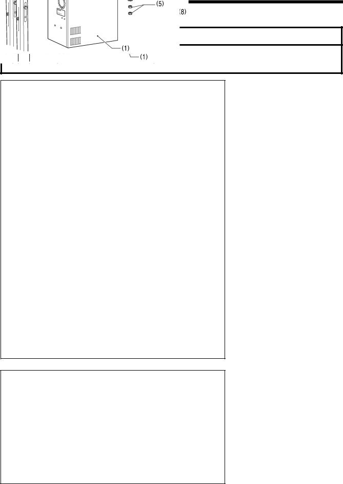
1. NAMES OF MAJOR PARTS
1. NAMES OF MAJOR PARTS
3462B
(1) |
STOP switch |
Safety devices: |
|
(2) |
Power switch |
(10) |
Finger guard |
(3) |
Work clamp switch |
(11) |
Eye guard |
(4) |
Start switch |
(12) |
Thread take-up cover |
(5) |
Control box |
(13) |
Motor cover |
(6)Solenoid valve
(7)LCD panel
(8)Pulley
(9)Cotton stand
1 |
BAS-341H, BAS-342H |
2. USEFUL FUNCTIONS FOR OPTIMUM SEWING
2. USEFUL FUNCTIONS FOR OPTIMUM SEWING
Easy threading in threading mode
 Page 24-25
When using threading mode for threading, the tension discs will open so that the thread can be threaded more easily.
Furthermore, threading mode is safe because the sewing machine will not start even when the start switch is depressed.
Presser foot height can be set easily using the
LCD panel or the control panel
 Page 39-41
The height of the presser foot can be set simply by entering a numeric value at the LCD panel or the control panel, without the need for tools.
Adjusting the driver needle guard is simple and within close reach.
Instruction Manual (*1)
7-6. Adjusting the driver (needle guard) position
The driver needle guard (1) can be adjusted easily and within close reach without tilting back the machine head.
3590B
2555Q
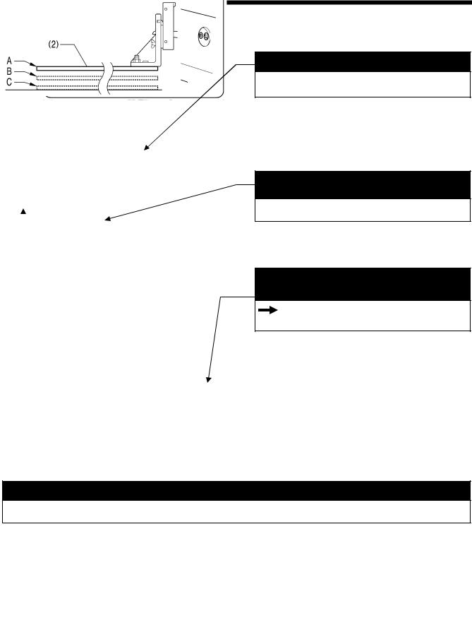
Work clamp lowering operation
 4-8. Setting 2-step operation for the work clamp
You can select one of two different types of dropping operation for the work clamp (2) by changing memory switch settings.
<Work clamp dropping in one step>
When the work clamp switch is depressed, the work clamp (2) drops in one movement from its highest position A to its lowest position C.
<Work clamp dropping in two steps>
1.When the work clamp switch is depressed to the 1st step, the work clamp (2) drops from its highest position A to the intermediate position B.
2.When the work clamp switch is then depressed to the 2nd
step, the work clamp (2) drops to its lowest position C. |
4057M |
(*1) Please download the Instruction Manual from our web site.
BAS-341H, BAS-342H |
2 |
3. INSTALLATION
3. INSTALLATION
 CAUTION
Machine installation should only be carried out |
Hold the machine head with both hands when |
|||
by a qualified technician. |
tilting it back or returning it to its original position. |
|||
Contact your Brother dealer or a qualified |
In addition, do not subject the machine head to |
|||
extra force |
while it is tilted back. If this is not |
|||
electrician for any electrical work that may need |
||||
observed, |
the machine head may |
become |
||
to be done. |
||||
unbalanced and fall down, and serious injury or |
||||
|
||||
The sewing machine head weighs approximately |
damage to the sewing machine may result. |
|||
160 kg. |
All cords should be secured at least 25 mm away |
|||
Use equipment such as a crane or hoist when |
||||
from any |
moving parts. Furthermore, |
do not |
||
installing the machine head and adjusting the |
||||
excessively bend the cords or secure them too |
||||
height of the table. |
||||
firmly staples, otherwise there is the danger that |
||||
If you try to lift the machine head yourself, it may |
||||
fire or electric shocks could occur. |
|
|||
cause injuries such as back injury. |
|
|||
Be sure to connect the ground. If the ground |
||||
Do not connect the power cord until installation is |
||||
connection is not secure, you run a high risk of |
||||
complete. |
||||
receiving a serious electric shock, and problems |
||||
If the foot switch is depressed by mistake, the |
||||
with correct operation may also occur. |
|
|||
sewing machine might start operating and injury |
|
|||
Install the safety covers to the machine head and |
||||
could result. |
||||
If using a work table which has casters, the |
motor. |
|
|
casters should be secured in such a way so that |
|
they cannot move. |
|
Use a table with a height of 84 cm or less. If the |
|
table is too high, the machine head may become |
|
unbalanced and fall down, and serious injury or |
|
damage to the sewing machine may result. |
|
3 |
BAS-341H, BAS-342H |
3. INSTALLATION
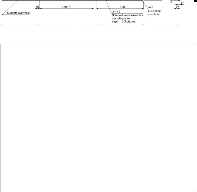
3-1. Table processing diagram
The thickness of the table should be at least 50 mm, and it should be strong enough to bear the weight and vibration of the sewing machine.
If using casters, use ones which can bear the total weight of sewing machine and table.
Check that the control box is at least 10 mm away from the leg. If the control box and the leg are too close together, it may result in incorrect sewing machine operation.
3635B
BAS-341H, BAS-342H |
4 |
3. INSTALLATION
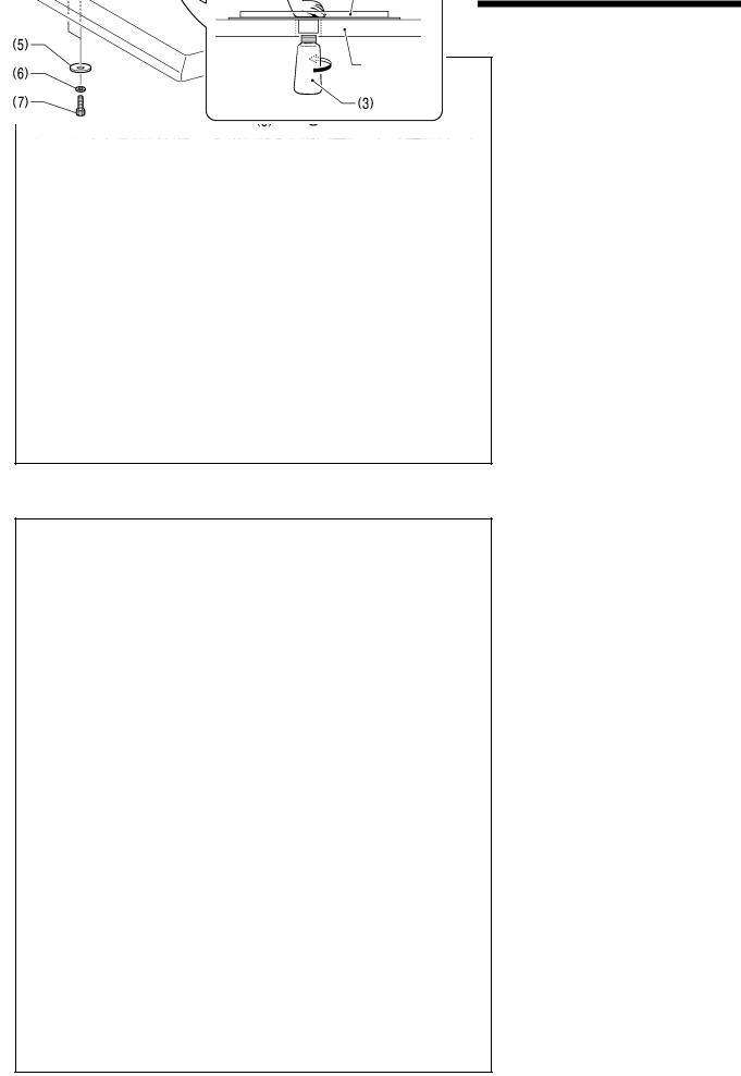
3-2. Installing the control box
 CAUTION
The control box is heavy, so installation should be carried out by two or more people.
In addition, take steps to make sure that the control box does not fall down.
If this is not done, injury to feet or damage to the control box may result.
3606B
(1) Control box
(2) Bolts [4 pcs.]
(3) Plain washers [4 pcs.]
(4) Spring washers [4 pcs.]
(5) Nuts [8 pcs.]
NOTE:
Check that the control box (1) is at least 10 mm away from the leg. If the control box (1) and the leg are too close together, it may result in incorrect sewing machine operation.
10mm or more
Leg
3599B
(6) Power switch
(7) Wood screws [2 pcs.]
(8) Staples [7 pcs.]
NOTE:
Take care when tapping in the
Operator staples (8) to make sure that they do not pierce the power cord.
3608B
5 |
BAS-341H, BAS-342H |
3. INSTALLATION
3-3. Installing the oil pan and support lever base
|
(1) |
Oil pan |
|
||
|
(2) |
Wood screws [4 pcs.] |
|
(3) |
Oiler |
|
(4) |
Support lever base |
|
(5) |
Plain washers [2 pcs.] |
|
(6) |
Spring washers [2 pcs.] |
|
(7) |
Bolts [2 pcs.] |
|
|
|
Table
3964M
3-4. Installing the machine head
2585B
1.Place the machine head onto the table.
NOTE:
Use a crane or hoist to install the sewing machine.
Be careful of the following when lowering the machine head onto the table.
!Do not let any cords get clamped between the machine head and the table.
!Do not place the machine head cushion (c) on top of the oil pan
(a) or the support lever base (b).
!Do not let the side (d) of the machine head switch lever touch the support lever base (b).
(1)Rubber bushes (2 pcs.)
(2)Hinge holders (2 pcs.)
(3)Plain washers [4 pcs.]
(4)Spring washers [4 pcs.]
(5)Bolts [4 pcs.]
(Continued on next page)
BAS-341H, BAS-342H |
6 |
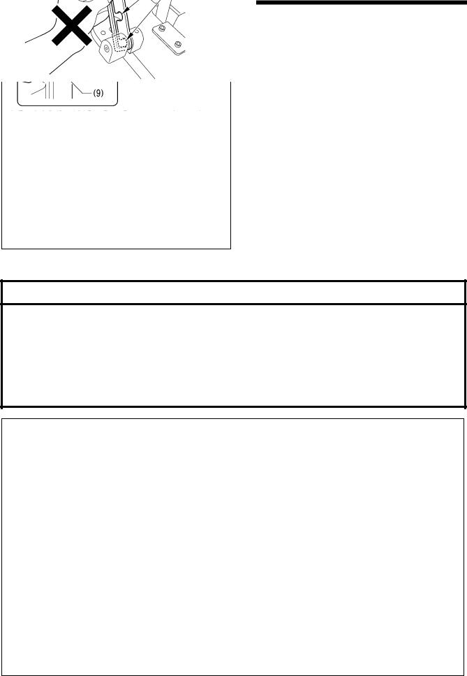
3. INSTALLATION
Flush
3601B
2.After placing the machine head onto the table, remove the bolt (6) and the spacer (7).
*The bolt (6) and the spacer (7) are necessary for securing the support lever (8) when the machine head is removed from the table, so keep them in a safe place.
3.Pass the support lever shaft (9) through the hole in the support lever base (10) and through the groove (f) in the support lever (8), and push it in until it is flush with the surface of the support lever base (10).
*Be sure to insert so that the groove (g) in the support lever shaft (9) faces in the direction shown in the illustration.
*If it is difficult to pass the support lever shaft (9) through the groove (f) in the support lever (8), move the end of the support lever (8) up and down while passing the support lever shaft (9) through.
3-5. Tilting back and returning the machine head
 CAUTION
Hold the machine head with both hands when tilting it back or returning it to its original position.
In addition, do not subject the machine head to extra force while it is tilted back. If this is not observed, the machine head may become unbalanced and fall down, and serious injury or damage to the sewing machine may result.
Always be sure to engage the stopper of the support lever (1) when tilting back the machine head.
If the stopper is not engaged, the machine head may return to its original position and your hands may get caught and injury may result.
When disengaging the stopper, hold it by the knob (a).
If you hold at the place indicated by (b), your hand will get caught between the support lever (1) and the table when the machine head is returned to its original position and injury will result.
Disengaging the stopper
Engaging the stopper
The machine head can be tilted back and returned to one of three heights.
3967M
7 |
BAS-341H, BAS-342H |
Loading...