


 Loading...
Basic Operation Manual
BAS-342G PS
DIRECT DRIVE
PROGRAMMABLE ELECTRONIC PATTERN SEWER
<PERFECT STITCH>
Please read this manual before using the machine.
Please keep this manual within easy reach for quick reference.
This basic operation manual describes basic operations including sewing machine operations.
For cleaning, standard adjustments and more details, please refer to the instruction manual contained in the Document CD.
Thank you very much for buying a BROTHER sewing machine. Before using your new machine, please read the safety instructions below and the explanations given in the instruction manual.
With industrial sewing machines, it is normal to carry out work while positioned directly in front of moving parts such as the needle and thread take-up lever, and consequently there is always a danger of injury that can be caused by these parts. Follow the instructions from training personnel and instructors regarding safe and correct operation before operating the machine so that you will know how to use it correctly.
BAS-342G PS

SAFETY INSTRUCTIONS
[1] Safety indications and their meanings
This instruction manual and the indications and symbols that are used on the machine itself are provided in order to ensure safe operation of this machine and to prevent accidents and injury to yourself or other people.
The meanings of these indications and symbols are given below.
Indications
 DANGER
 CAUTION
IMPORTANT
Symbols
The instructions which follow this term indicate situations where failure to follow the instructions will result in death or serious injury.
The instructions which follow this term indicate situations where failure to follow the instructions may result in minor or moderate injury.
The instructions which follow this term indicate situations where failure to follow the instructions may result in physical damage to equipment and surroundings or result in problems with equipment operation.


This symbol (  ) indicates something that you should be careful of. The picture inside the triangle indicates the nature of the caution that must be taken.
(For example, the symbol at left means “beware of injury”.)
This symbol (  ) indicates something that you must not do.
This symbol ( ) indicates something that you must do. The picture inside the circle indicates the nature of the thing that must be done.
(For example, the symbol at left means “you must make the ground connection”.)
BAS-342G PS |
i |

[2] Notes on safety
 DANGER
Wait at least 5 minutes after turning off the power switch and disconnecting the power cord from the wall outlet before opening the cover of the control box. Touching areas where high voltages are present can result in severe injury.
 CAUTION
Environmental requirements
Use the sewing machine in an area which is free from sources of strong electrical noise such as electrical line noise or static electric noise.
Sources of strong electrical noise may cause problems with correct operation.
Any fluctuations in the power supply voltage should be within ±10% of the rated voltage for the machine. Voltage fluctuations which are greater than this may cause problems with correct operation.
The power supply capacity should be greater than the requirements for the sewing machine's power consumption.
Insufficient power supply capacity may cause problems with correct operation.
The pneumatic delivery capability should be greater than the requirements for the sewing machine's total air consumption.
Insufficient pneumatic delivery capability may cause problems with correct operation.
The ambient temperature should be within the range of 5°C to 35°C during use.
Temperatures which are lower or higher than this may cause problems with correct operation.
The relative humidity should be within the range of 45% to 85% during use, and no dew formation should occur in any devices.
Excessively dry or humid environments and dew formation may cause problems with correct operation.
In the event of an electrical storm, turn off the power and disconnect the power cord from the wall outlet. Lightning may cause problems with correct operation.
Installation
Machine installation should only be carried out by a qualified technician.
Contact your Brother dealer or a qualified electrician for any electrical work that may need to be done.
The sewing machine weighs approximately 160 kg. Use equipment such as a crane or hoist when installing the machine head and adjusting the height of the table.
If you try to lift the machine head yourself, it may cause injuries such as back injury.
Do not connect the power cord until installation is complete. If the foot switch is depressed by mistake, the sewing machine might start operating and injury could result.
Hold the machine head with both hands when tilting it back or returning it to its original position.
In addition, do not subject the machine head to extra force while it is tilted back. If this is not observed, the machine head may become unbalanced and fall down, and serious injury or damage to the sewing machine may result.
Be sure to connect the ground. If the ground connection is not secure, you run a high risk of receiving a serious electric shock, and problems with correct operation may also occur.
All cords should be secured at least 25 mm away from any moving parts. Furthermore, do not excessively bend the cords or secure them too firmly with staples, otherwise there is the danger that fire or electric shocks could occur.
Install the safety covers to the machine head and motor.
If using a work table which has casters, the casters should be secured in such a way so that they cannot move.
Use a table with a height of 84 cm or less. If the table is too high, the machine head may become unbalanced and fall down, and serious injury or damage to the sewing machine may result.
Be sure to wear protective goggles and gloves when handling the lubricating oil and grease, so that they do not get into your eyes or onto your skin. If the oil and grease get into your eyes or onto your skin, inflammation can result.
Furthermore, do not drink or eat the lubricating oil or grease. They may cause diarrhea or vomiting.
Keep the oil out of the reach of children.
ii |
BAS-342G PS |

 CAUTION
Sewing
This sewing machine should only be used by |
If using a work table which has casters, the casters |
|
operators who have received the necessary training |
should be secured in such a way so that they cannot |
|
in safe use beforehand. |
move. |
|
The sewing machine should not be used for any |
Attach all safety devices before using the sewing |
|
applications other than sewing. |
machine. If the machine is used without these |
|
Be sure to wear protective goggles when using the |
devices attached, injury may result. |
|
|
||
machine. |
Do not touch any of the moving parts or press any |
|
If goggles are not worn, there is the danger that if a |
objects against the machine while sewing, as this |
|
needle breaks, parts of the broken needle may enter |
may result in personal injury or damage to the |
|
your eyes and injury may result. |
machine. |
|
Turn off the power switch at the following times. If the |
If an error occurs in machine operation, or if abnormal |
|
foot switch is depressed by mistake, the sewing |
noises or smells are noticed, immediately turn off the |
|
machine might start operating and injury could result. |
power switch. Then contact your nearest Brother |
|
• When threading the needle |
dealer or a qualified technician. |
|
• When replacing the bobbin and needle |
If the machine develops a problem, contact your |
|
• When not using the machine and when leaving the |
||
nearest Brother dealer or a qualified technician. |
||
machine unattended |
||
|
||
|
||
Cleaning |
||
Turn off the power switch before carrying out |
Be sure to wear protective goggles and gloves when |
|
cleaning. If the foot switch is depressed by mistake, |
handling the lubricating oil and grease, so that they |
|
the sewing machine might start operating and injury |
do not get into your eyes or onto your skin. If the oil |
|
could result. |
and grease get into your eyes or onto your skin, |
|
|
inflammation can result. |
|
|
Furthermore, do not drink or eat the lubricating oil or |
|
|
grease. They may cause diarrhea or vomiting. |
|
|
Keep the oil out of the reach of children. |
|
Maintenance and inspection |
||
Maintenance and inspection of the sewing machine |
If the power switch and air need to be left on when |
|
should only be carried out by a qualified technician. |
carrying out some adjustment, be extremely careful to |
|
Ask your Brother dealer or a qualified electrician to |
observe all safety precautions. |
|
|
||
carry out any maintenance and inspection of the |
When replacing parts and installing optional |
|
electrical system. |
accessories, be sure to use only genuine Brother |
|
Turn off the power switch and disconnect the power |
parts. |
|
cord before carrying out the following operations. If |
Brother will not be held responsible for any accidents |
|
the foot switch is depressed by mistake, the sewing |
or problems resulting from the use of non-genuine |
|
machine might start operating and injury could result. |
parts. |
|
• Inspection, adjustment and maintenance |
If any safety devices have been removed, be |
|
• Replacing consumable parts such as the rotary hook |
absolutely sure to re-install them to their original |
|
Disconnect the air hoses from the air supply and wait |
positions and check that they operate correctly before |
|
using the machine. |
||
for the needle on the pressure gauge to drop to “0” |
||
before carrying out inspection, adjustment and repair |
To prevent accidents and problems, do not modify |
|
of any parts which use the pneumatic equipment. |
the machine yourself. |
|
Hold the machine head with both hands when tilting it |
Brother will not be held responsible for any accidents |
|
or problems resulting from modifications made to the |
||
back or returning it to its original position. |
||
machine. |
||
In addition, do not subject the machine head to extra |
||
force while it is tilted back. If this is not observed, the machine head may become unbalanced and fall down, and serious injury or damage to the sewing machine may result.
IMPORTANT
Do not allow any liquids to get onto this sewing machine, otherwise smoke or fire may occur.
If any liquid gets inside the sewing machine (machine head or control box), immediately turn off the power and disconnect the power plug from the electrical outlet, and then contact the place of purchase or a qualified technician.
BAS-342G PS |
iii |

[3] Warning labels
The following warning labels appear on the sewing machine.
Please follow the instructions on the labels at all times when using the machine. If the labels have been removed or are difficult to read, please contact your nearest Brother dealer.
1
2
*Safety devices
Devices such as eye guard, finger guard, thread take-up cover, motor cover, X motor cover, tension release solenoid cover, inside cover, outside cover, middle cover, fixed cover and rear cover
3 
4
5
Be careful to avoid getting hands caught in sliding parts.
Be sure to connect the ground. If the ground connection is not secure, you run a high risk of receiving a serious electric shock, and problems with correct operation may also occur.
Direction of operation
iv |
BAS-342G PS |

Rear cover
Thread take-up cover
Eye guard
Finger guard
Motor cover
Rear cover
Rear cover
Inside cover R
Middle cover
Outside cover
Fixed cover
Tension release solenoid cover Inside cover L
Middle cover
Outside cover
Fixed cover
X motor cover
2740B
BAS-342G PS |
v |
CONTENTS
1. NAMES OF MAJOR PARTS ................ |
1 |
2. USEFUL FUNCTIONS |
|
FOR OPTIMUM SEWING ..................... |
2 |
3. TABLE PROCESSING DIAGRAM ....... |
3 |
4. INSTALLATION.................................... |
4 |
4-1. Removing the machine head fixing bolts [1]..... |
4 |
4-2. Installing the control box [2].............................. |
5 |
4-3. Installing the oil pan and support lever base .... |
6 |
4-4. Installing the machine head.............................. |
6 |
4-5. Tilting back and returning the machine head ... |
7 |
4-6. Installing the gas spring.................................... |
8 |
4-7. Installing the operation panel [3]....................... |
9 |
4-8. Installing the solenoid valve assembly ............. |
10 |
4-9. Connecting the air tubes [4].............................. |
10 |
4-10. Installing the air hose [5]................................. |
10 |
4-11. Adjusting the air pressure [6].......................... |
11 |
4-12. Adjusting the speed controller [7] ................... |
11 |
4-13. Connecting the cords [8]................................. |
12 |
4-14. Connecting the ground wire [9] ...................... |
14 |
4-15. Securing the cords and air tubes [10]............. |
15 |
4-16. Installing the eye guard [11] ........................... |
16 |
4-17. Installing the cotton stand [12]........................ |
16 |
4-18. Lubrication [13] ............................................... |
17 |
4-19. Connecting the power cord [14] ..................... |
18 |
4-20. Checking the safety switch [15]...................... |
18 |
5. PREPARATION BEFORE SEWING..... |
19 |
5-1. Installing the needle.......................................... |
19 |
5-2. Operating the 2-pedal foot switch..................... |
19 |
5-3. Threading the upper thread .............................. |
20 |
5-4. Winding the lower thread.................................. |
22 |
5-5. Installing the bobbin case ................................. |
23 |
5-6. Thread tension.................................................. |
24 |
5-6-1. Lower thread tension.............................. |
24 |
5-6-2. Upper thread tension.............................. |
24 |
5-7. Home position detection ................................... |
25 |
6. USING THE OPERATION PANEL |
|
|
|
(BASIC OPERATIONS) ....................... |
26 |
6-1. Name and function of each operation |
|
|
|
panel item.......................................................... |
26 |
6-2. Loading sewing data ......................................... |
28 |
|
6-3. Setting the program number ............................. |
28 |
|
6-4. Setting the X-scale and Y-scale........................ |
29 |
|
6-5. Setting the sewing speed.................................. |
29 |
|
6-6. Checking the sewing pattern............................. |
30 |
|
6-7. Setting the height of the intermittent presser foot... |
31 |
|
6-8. |
Notes on handling CF cards (sold separately) ... |
32 |
7. SEWING ............................................... |
33 |
|
7-1. |
Sewing .............................................................. |
33 |
7-2. |
Using the STOP switch ..................................... |
34 |
7-3. |
Using the thread wiper switch ........................... |
34 |
Document CD ........................................... |
36 |
|
BAS-342G PS

1. NAMES OF MAJOR PARTS
1. NAMES OF MAJOR PARTS
2741B
(1) |
STOP switch |
Safety devices: |
|
(2) |
CF slot |
(12) |
Finger guard |
(3) |
Power switch |
(13) |
Eye guard |
(4) |
Work clamp switch |
(14) |
Thread take-up cover |
(5) |
Start switch |
(15) |
Motor cover |
(6)Control box
(7)Solenoid valve
(8)Operation panel
(9)Thread wiper switch
(10)Pulley
(11)Cotton stand
CFTM is a trademark of SanDisk Corporation.
BAS-342G PS |
1 |
2. USEFUL FUNCTIONS FOR OPTIMUM SEWING
2. USEFUL FUNCTIONS FOR OPTIMUM SEWING
The lower thread can be easily threaded using the threading bar
 Page 23
If you clamp the lower thread in the thread hold spring (1) and then push it gently using the threading bar (2), you can make the lower thread pass easily through the window (3) of the inner rotary hook.
Easy threading in threading mode
 Page 21
When using threading mode for threading, the tension discs will open so that the thread can be threaded more easily.
Furthermore, threading mode is safe because the sewing machine will not start even when the foot switch is depressed.
Intermittent presser foot height can be set easily using the panel
 Page 31
INSTRUCTION MANUAL CD 7-7. Using user programs
The height of the intermittent presser foot can be set simply by entering a numeric value at the panel, without the need for tools.
Furthermore, you can use user programs to set the intermittent presser foot height to the desired height separately for each sewing program.
Easy and accurate feed plate replacement
 INSTRUCTION MANUAL CD 11-10-1. Installing the feed plate
The feed plate installation position can be obtained accurately by using the panel, which makes feed plate replacement much easier.
Feed plate installation mode
|
|
2919B |
|
|
2920B |
|
|
|
|
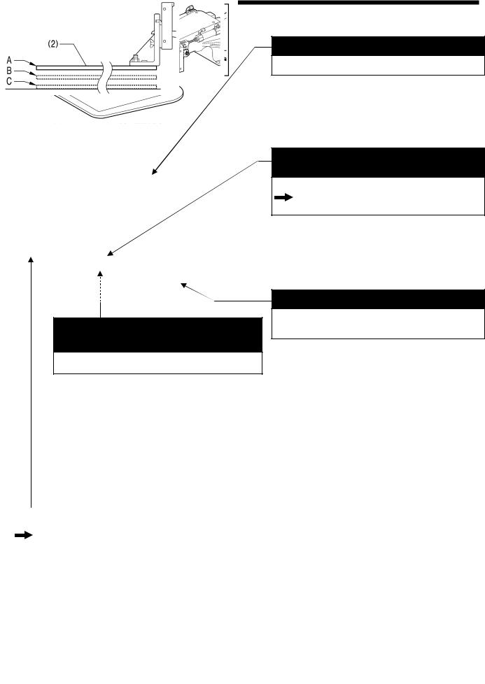
Two types of work clamp dropping operation |
|
|
|
|
INSTRUCTION MANUAL CD |
5-8. Setting 2-step operation for the work clamp |
|
|
7-2. |
Setting memory switches |
|
7-3. |
List of memory switch settings |
|
|
|
You can select one of two different types of dropping operation for the work clamp (2) by changing memory switch settings.
<Work clamp dropping in one step>
When the work clamp switch is depressed, the work clamp (2) drops in one movement from its highest position A to its lowest position C.
<Work clamp dropping in two steps>
1.When the work clamp switch is depressed to the 1st step, the work clamp (2) drops from its highest position A to the intermediate position B.
2.When the work clamp switch is then depressed to the 2nd step, the work clamp (2) drops to its lowest position C.
4057M
2 |
BAS-342G PS |
3. TABLE PROCESSING DIAGRAM
3. TABLE PROCESSING DIAGRAM
•The thickness of the table should be at least 50 mm, and it should be strong enough to bear the weight and vibration of the sewing machine.
•If using casters, use ones which can bear the total weight of sewing machine and table.
•Check that the control box is at least 10 mm away from the leg. If the control box and the leg are too close together, it may result in incorrect sewing machine operation.
4053M
BAS-342G PS |
3 |

4. INSTALLATION
4. INSTALLATION
 CAUTION
Machine installation should only be carried out by a |
Hold the machine head with both hands when tilting it |
|
qualified technician. |
back or returning it to its original position. |
|
Contact your Brother dealer or a qualified electrician for |
In addition, do not subject the machine head to extra |
|
force while it is tilted back. If this is not observed, the |
||
any electrical work that may need to be done. |
||
machine head may become unbalanced and fall down, |
||
The sewing machine head weighs approximately 160 |
||
and serious injury or damage to the sewing machine |
||
kg. |
may result. |
|
Use equipment such as a crane or hoist when installing |
All cords should be secured at least 25 mm away from |
|
the machine head and adjusting the height of the table. |
||
any moving parts. Furthermore, do not excessively bend |
||
If you try to lift the machine head yourself, it may cause |
||
the cords or secure them too firmly staples, otherwise |
||
injuries such as back injury. |
||
there is the danger that fire or electric shocks could |
||
Do not connect the power cord until installation is |
||
occur. |
||
complete. |
Be sure to connect the ground. If the ground connection |
|
If the foot switch is depressed by mistake, the sewing |
||
is not secure, you run a high risk of receiving a serious |
||
machine might start operating and injury could result. |
||
electric shock, and problems with correct operation may |
||
If using a work table which has casters, the casters |
||
also occur. |
||
should be secured in such a way so that they cannot |
Install the safety covers to the machine head and motor. |
|
move. |
||
|
||
Use a table with a height of 84 cm or less. If the table is |
|
|
too high, the machine head may become unbalanced |
|
|
and fall down, and serious injury or damage to the |
|
|
sewing machine may result. |
|
When placing the sewing machine on the table
Carry out the procedure starting from "4-2. Installing the control box" on the next page.
If the sewing machine was already installed to the table when it was delivered
Carry out the procedures indicated by [1] to [15] in the titles in the order of the numbers.
4-1. Removing the machine head fixing bolts [1]
If the sewing machine was already installed to the table when it was delivered, remove the two machine head fixing bolts (1) and the two plain washers
(2).
2742B
4 |
BAS-342G PS |

4. INSTALLATION
4-2. Installing the control box [2]
CAUTION
The control box is heavy, so installation should be carried out by two or more people.
In addition, take steps to make sure that the control box does not fall down.
If this is not done, injury to feet or damage to the control box may result.
|
|
|
Before installing the control box (1), check |
||
3961M |
|||||
that the model plate (a) on the control box |
|||||
|
|
|
|||
|
|
|
(1) is “AX342G” to indicate that it is an |
||
|
|
|
RX-control box for BAS-342G sewing |
||
|
|
|
machines. |
||
|
|
|
* If the sewing machine is installed to the |
||
|
|
|
table, tilt back the machine head. |
||
|
|
|
(Refer to "4-5. Tilting back and returning |
||
|
|
|
the machine head".) |
||
|
|
|
(1) |
Control box |
|
|
|
|
(2) |
Bolts [4 pcs.] |
|
|
|
|
(3) |
Plain washers [4 pcs.] |
|
|
|
|
(4) |
Spring washers [4 pcs.] |
|
|
|
|
(5) |
Nuts [8 pcs.] |
|
|
|
|
NOTE: |
||
|
|
|
|
Check that the control box (1) is at |
|
|
|
|
|
least 10 mm away from the leg. If the |
|
|
|
|
|
control box (1) and the leg are too |
|
|
|
|
|
close together, it may result in |
|
|
|
|
|
incorrect sewing machine operation. |
|
10mm or more
Leg
3962M
(6) Power switch
(7) Wood screws [2 pcs.]
(8) Staples [7 pcs.]
NOTE:
Take care when tapping in the staples
(8) to make sure that they do not
pierce the power cord.
Operator
3963M
BAS-342G PS |
5 |

4. INSTALLATION
4-3. Installing the oil pan and support lever base
(1) |
Oil pan |
|
|
(2) |
Wood screws [4 pcs.] |
|
(3) |
Oiler |
|
(4) |
Support lever base |
|
(5) |
Plain washers [2 pcs.] |
|
(6) |
Spring washers [2 pcs.] |
|
(7) |
Bolts [2 pcs.] |
|
|
|
|
|
|
Table
3964M
4-4. Installing the machine head
1. Place the machine head onto the table.
NOTE:
• Use a crane or hoist to install the sewing machine.
• Be careful of the following when lowering the machine head onto the table.
! Do not let any cords get clamped between the machine head and the table.
! Do not place the machine head cushion (c) on top of the oil pan
(a) or the support lever base (b). ! Do not let the side (d) of the
safety switch lever touch the support lever base (b).
(1) Rubber bushes (2 pcs.)
(2) Hinge holders (2 pcs.)
(3) Plain washers [4 pcs.]
(4) Spring washers [4 pcs.]
(5) Bolts [4 pcs.]
2743B
(Continued on next page)
6 |
BAS-342G PS |
Loading...