


 Loading...
BAS-311G BAS-326G
SERVICE MANUAL
Please read this manual before making any adjustments.
DIRECT DRIVE
PROGRAMMABLE ELECTRONIC PATTERN SEWER

This service manual is intended for BAS-311G, BAS-326G; be sure to read the BAS-311G, BAS-326G instruction manual before this manual.
Carefully read the “SAFETY INSTRUCTIONS” below and the whole of this manual to understand this product before you start maintenance.
As a result of research and improvements regarding this product, some details of this manual may not be the same as those for the product you purchased.
If you have any questions regarding this product, please contact a Brother dealer.
SAFETY INSTRUCTIONS
[1] Safety indications and their meanings
This service manual and the indications and symbols that are used on the machine itself are provided in order to ensure safe operation of this machine and to prevent accidents and injury to yourself or other people.
The meanings of these indications and symbols are given below.
Indications
DANGER The instructions which follow this term indicate situations where failure to follow the instructions may result in death or serious injury.
The instructions which follow this term indicate situations where failure to follow the CAUTION instructions could cause injury when using the machine or physical damage to equipment
and surroundings.
Symbols


This symbol (  ) indicates something that you should be careful of. The picture inside the triangle indicates the nature of the caution that must be taken.
(For example, the symbol at left means “beware of injury”.)
This symbol (  ) indicates something that you must not do.
This symbol ( ) indicates something that you must do. The picture inside the circle indicates the nature of the thing that must be done.
(For example, the symbol at left means “you must make the ground connection”.)
BAS-311G, BAS-326G |
i |

[2] Notes on safety
 DANGER
Wait at least 5 minutes after turning off the power switch and disconnecting the power cord from the wall outlet before opening the cover of the control box. Touching areas where high voltages are present can result in severe injury.
 CAUTION
Environmental requirements
Use the sewing machine in an area which is free from sources of strong electrical noise such as electrical line noise or static electric noise.
Sources of strong electrical noise may cause problems with correct operation.
Any fluctuations in the power supply voltage should be within ±10% of the rated voltage for the machine. Voltage fluctuations which are greater than this may cause problems with correct operation.
The power supply capacity should be greater than the requirements for the sewing machine's power consumption.
Insufficient power supply capacity may cause problems with correct operation.
The pneumatic delivery capability should be greater than the requirements for the sewing machine's total air consumption.
Insufficient pneumatic delivery capability may cause problems with correct operation.
The ambient temperature should be within the range of 5°C to 35°C during use.
Temperatures which are lower or higher than this may cause problems with correct operation.
The relative humidity should be within the range of 45% to 85% during use, and no dew formation should occur in any devices.
Excessively dry or humid environments and dew formation may cause problems with correct operation.
In the event of an electrical storm, turn off the power and disconnect the power cord from the wall outlet. Lightning may cause problems with correct operation.
Installation
Machine installation should only be carried out by a qualified technician.
Contact your Brother dealer or a qualified electrician for any electrical work that may need to be done.
The sewing machine weighs approximately 88 kg. The installation should be carried out by two or more people.
Do not connect the power cord until installation is complete. If the foot switch is depressed by mistake, the sewing machine might start operating and injury could result.
Hold the machine head with both hands when tilting it back or returning it to its original position. Furthermore, do not apply excessive force when tilting back the machine head. The sewing machine may become unbalanced and fall down, and serious injury or damage to the sewing machine may result.
Be sure to connect the ground. If the ground connection is not secure, you run a high risk of receiving a serious electric shock, and problems with correct operation may also occur.
All cords should be secured at least 25 mm away from any moving parts. Furthermore, do not excessively bend the cords or secure them too firmly with staples, otherwise there is the danger that fire or electric shocks could occur.
Install the safety covers to the machine head and motor.
If using a work table which has casters, the casters should be secured in such a way so that they cannot move.
Be sure to wear protective goggles and gloves when handling the lubricating oil and grease, so that they do not get into your eyes or onto your skin. If the oil and grease get into your eyes or onto your skin, inflammation can result.
Furthermore, do not drink or eat the lubricating oil or grease. They may cause diarrhea or vomiting.
Keep the oil out of the reach of children.
ii |
BAS-311G, BAS-326G |

CAUTION |
|
|
|
|
||
Sewing |
|
|
|
|
|
|
This sewing machine should only be used by |
If using a work table which has casters, the casters |
|||||
operators who have received the necessary training |
should be secured in such a way so that they cannot |
|||||
in safe use beforehand. |
move. |
|
|
|
|
|
The sewing machine should not be used for any |
Attach all safety devices before using the sewing |
|||||
applications other than sewing. |
machine. If the machine is used without these |
|||||
Be sure to wear protective goggles when using the |
devices attached, injury may result. |
|
|
|
||
machine. |
Do not touch any of the moving parts or press any |
|||||
If goggles are not worn, there is the danger that if a |
||||||
objects against |
the machine while |
sewing, |
as |
this |
||
needle breaks, parts of the broken needle may enter |
||||||
may result in |
personal injury or |
damage |
to |
the |
||
your eyes and injury may result. |
||||||
machine. |
|
|
|
|
||
Turn off the power switch at the following times. If the |
|
|
|
|
||
If an error occurs in machine operation, or if abnormal |
||||||
foot switch is depressed by mistake, the sewing |
||||||
noises or smells are noticed, immediately turn off the |
||||||
machine might start operating and injury could result. |
||||||
power switch. Then contact your |
nearest |
Brother |
||||
• When threading the needle |
||||||
dealer or a qualified technician. |
|
|
|
|||
• When replacing the bobbin and needle |
|
|
|
|||
|
|
|
|
|
||
• When not using the machine and when leaving the |
If the machine develops a problem, contact your |
|||||
machine unattended |
nearest Brother dealer or a qualified technician. |
|
||||
|
|
|
|
|
||
Cleaning |
|
|
|
|
||
Turn off the power switch before carrying out |
Be sure to wear protective goggles and gloves when |
|||||
cleaning. If the foot switch is depressed by mistake, |
handling the lubricating oil and grease, so that they |
|||||
the sewing machine might start operating and injury |
do not get into your eyes or onto your skin. If the oil |
|||||
could result. |
and grease get into your eyes or onto your skin, |
|||||
|
inflammation can result. |
|
|
|
||
|
Furthermore, do not drink or eat the lubricating oil or |
|||||
|
grease. They may cause diarrhea or vomiting. |
|
|
|||
|
Keep the oil out of the reach of children. |
|
|
|||
|
|
|
|
|||
Maintenance and inspection |
|
|
|
|||
Maintenance and inspection of the sewing machine |
Hold the machine head with both hands when tilting it |
|||||
should only be carried out by a qualified technician. |
back or returning it to its original position. |
|
|
|||
Ask your Brother dealer or a qualified electrician to |
Furthermore, do not apply excessive force when |
|||||
tilting back the machine head. The sewing machine |
||||||
carry out any maintenance and inspection of the |
||||||
may become unbalanced and fall down, and serious |
||||||
electrical system. |
||||||
injury or damage to the sewing machine may result. |
||||||
Turn off the power switch and disconnect the power |
||||||
If the power switch needs to be left on when carrying |
||||||
cord before carrying out the following operations. If |
||||||
out some adjustment, be extremely careful to observe |
||||||
the foot switch is depressed by mistake, the sewing |
||||||
all safety precautions. |
|
|
|
|||
machine might start operating and injury could result. |
|
|
|
|||
Use only the proper replacement parts as specified |
||||||
• Inspection, adjustment and maintenance |
||||||
• Replacing consumable parts such as the rotary |
by Brother. |
|
|
|
|
|
hook |
If any safety devices have been removed, be |
|||||
Disconnect the air hoses from the air supply and wait |
absolutely sure |
to re-install them |
to their |
original |
||
positions and check that they operate correctly before |
||||||
for the needle on the pressure gauge to drop to “0” |
||||||
using the machine. |
|
|
|
|||
before carrying out inspection, adjustment and repair |
|
|
|
|||
of any parts which use the pneumatic equipment. |
Any problems in machine operation which result from |
|||||
|
unauthorized modifications to the machine will not be |
|||||
|
covered by the warranty. |
|
|
|
||
|
|
|
|
|
||
BAS-311G, BAS-326G |
|
|
|
iii |
||
[3] Warning labels
The following warning labels appear on the sewing machine.
Please follow the instructions on the labels at all times when using the machine. If the labels have been removed or are difficult to read, please contact your nearest Brother dealer.
1
3
4
5
2
Be careful not to get your hand caught when tilting back the machine head and returning it to its original position.
Be sure to connect the ground. If the ground connection is not secure, you run a high risk of receiving a serious electric shock, and problems with correct operation may also occur.
Direction of operation
Safety devices
Devices such as eye guard, finger guard, thread take-up cover, motor cover, tension release solenoid cover, inner cover, outer cover, fixed cover and gas spring support cover
Motor cover |
Tension release |
|
solenoid cover |
|
Inner cover L |
|
Outer cover |
|
Fixed cover L |
Thread take-up cover
Motor cover L
Inner cover R
Eye guard Outer cover
Fixed cover R
Motor cover R
Finger guard
|
Gas spring support cover |
5222Q |
4905Q |
|
|
iv |
BAS-311G, BAS-326G |
CONTENTS
1. |
SPECIFICATIONS ............................. |
1 |
|
2. |
FUNCTION SETTINGS...................... |
2 |
|
2-1. List of special functions when power is |
|
||
|
|
turned on................................................... |
2 |
2-2. List of advanced functions......................... |
3 |
||
2-3. Memory switch setting method |
|
||
|
|
(Advanced) .............................................. |
4 |
2-4. List of memory switch settings .................. |
5 |
||
2-5. Setting the work clamp mode.................... |
14 |
||
2-6. Stitch counter checking method ................ |
15 |
||
2-7. Error history checking method .................. |
16 |
||
2-8. |
Input checking method .............................. |
17 |
|
2-9. |
Output checking method ........................... |
20 |
|
2-10. Software version checking method ........... |
22 |
||
3. READING / WRITING DATA ............. |
23 |
||
3-1. |
Handling data ............................................ |
23 |
|
3-2. Notes on handling CF cards |
|
||
|
|
(sold separately) ...................................... |
24 |
3-3. Structure of a CF card folder..................... |
24 |
||
3-4. |
Data read/write mode................................ |
25 |
|
3-5. Reading sewing data from CF cards ......... |
26 |
||
3-6. Writing sewing data to CF cards ............... |
27 |
||
3-7. Reading memory switch data from |
|
||
|
|
CF cards.................................................... |
28 |
3-8. Writing memory switch data to CF cards... |
28 |
||
3-9. Reading user program data from |
|
||
|
|
CF cards.................................................... |
29 |
3-10. Writing user program data to CF cards ..... |
29 |
||
3-11. Updating the control program.................... |
30 |
||
3-12. Writing error log data to CF card............... |
31 |
||
3-13. Reading sewing data from floppy disks..... |
31 |
||
3-14. Writing sewing data to floppy disks ........... |
32 |
||
3-15. Reading extended option output data |
|
||
|
|
from a CF card .......................................... |
33 |
3-16. Writing extended option output data |
|
||
|
|
to CF cards................................................ |
34 |
3-17. Reading extended option output data |
|
||
|
|
from floppy disks ....................................... |
34 |
4. |
MECHANICAL DESCRIPTIONS ....... |
35 |
|
4-1. Needle bar and thread take-up |
|
||
|
|
mechanisms .............................................. |
35 |
4-2. Lower shaft and shuttle race |
|
||
|
|
mechanisms .............................................. |
35 |
4-3. Work clamp lifter mechanism |
|
||
|
|
(Solenoid specifications) .......................... |
36 |
4-4. Work clamp lifter mechanism |
|
||
|
|
(Pneumatic specifications) ....................... |
37 |
4-5. Intermittent presser foot lifter |
|
||
|
|
mechanism ................................................ |
37 |
4-6. Intermittent presser foot stroke |
|
||
|
|
mechanism ................................................ |
38 |
4-7. |
Feed mechanism ....................................... |
39 |
|
4-8. |
Thread trimmer mechanism....................... |
40 |
|
4-9. |
Tension release mechanism...................... |
41 |
|
4-10. Thread wiper mechanism .......................... |
41 |
||
5. |
DISASSEMBLY ................................. |
42 |
|
5-1. |
Covers ....................................................... |
42 |
|
5-2. |
Thread wiper mechanism .......................... |
43 |
|
5-3. Work clamp arm mechanism ..................... |
44 |
||
5-4. Intermittent presser foot lifter |
|
||
|
|
mechanism (1) ......................................... |
45 |
5-5. |
Needle bar mechanism.............................. |
46 |
|
5-6. |
Upper shaft mechanism............................. |
47 |
|
5-7. |
Lower shaft mechanism............................. |
48 |
|
5-8. |
Feed covers............................................... |
49 |
|
5-9. |
Feed mechanism ....................................... |
50 |
|
5-10. Work clamp lifter mechanism |
|
||
|
|
(Solenoid specifications) .......................... |
53 |
5-11. Work clamp lifter mechanism |
|
||
|
|
(Pneumatic specifications) ....................... |
54 |
5-12. Tension release mechanism...................... |
55 |
||
5-13. Intermittent presser foot lifter |
|
||
|
|
mechanism (2) ......................................... |
55 |
5-14. Thread trimmer mechanism....................... |
56 |
||
5-15. Shuttle hook mechanism ........................... |
57 |
||
BAS-311G, BAS-326G
6. ASSEMBLY ......................................... |
58 |
|
6-1. Thread trimmer mechanism (1) ............... |
58 |
|
6-2. Intermittent presser foot lifter |
|
|
|
mechanism (1) ......................................... |
60 |
6-3. |
Tension release mechanism ..................... |
60 |
6-4. Work clamp lifter mechanism |
|
|
|
(Solenoid specifications) ......................... |
61 |
6-5. Work clamp lifter mechanism |
|
|
|
(Pneumatic specifications) ...................... |
64 |
6-6. |
Feed mechanism....................................... |
66 |
6-7. |
Feed covers .............................................. |
73 |
6-8. |
Upper shaft mechanism ............................ |
75 |
6-9. |
Needle bar mechanism ............................. |
77 |
6-10. Intermittent presser foot lifter |
|
|
|
mechanism (2) ......................................... |
79 |
6-11. Lower shaft mechanism ............................ |
81 |
|
6-12. Shuttle hook mechanism........................... |
83 |
|
6-13. Thread trimmer mechanism (2) ............... |
83 |
|
6-14. Work clamp arm mechanism..................... |
84 |
|
6-14-1. Adjustments after work clamp arm |
|
|
|
installation ......................................... |
85 |
6-15. Thread wiper mechanism.......................... |
86 |
|
6-16. Covers....................................................... |
87 |
|
7. ADJUSTMENT .................................... |
88 |
|
7-1. Checking the machine head switch........... |
88 |
|
7-2. |
Standard thread tension............................ |
89 |
7-2-1. Upper and lower thread tension ........ |
89 |
|
7-2-2. Thread take-up spring....................... |
90 |
|
7-2-3. Arm thread guide R........................... |
90 |
|
7-3. Adjusting the needle bar height................. |
91 |
|
7-4. Adjusting the needle bar lift amount.......... |
91 |
|
7-5. Adjusting the driver needle guard.............. |
91 |
|
7-6. Adjusting the needle clearance ................. |
92 |
|
7-7. Adjusting the shuttle race thread guide..... |
92 |
|
7-8. Rotary hook lubrication amount................. |
92 |
|
7-9. Adjusting the position of the movable |
|
|
|
knife .......................................................... |
93 |
7-10. Replacing the movable and fixed knives ... |
95 |
7-10-1. Installing the feed plate...................... |
96 |
7-11. Adjusting the thread wiper ......................... |
97 |
7-12. Presser foot installation position ................ |
97 |
7-13. Changing the intermittent stroke................ |
98 |
7-14. Adjusting the work clamp lift amount ......... |
100 |
7-15. Adjusting the air pressure |
|
(pneumatic specifications) ......................... |
100 |
7-16. Adjusting the thread trimmer cam |
|
position ...................................................... |
101 |
7-17. Belt tension adjustment ............................. |
101 |
7-18. Adjusting the tension release amount........ |
102 |
7-19. Adjusting the backlash of the lower |
|
shaft gear................................................... |
103 |
7-20. Adjusting the home position....................... |
104 |
7-20-1. Work clamp lift home position............ |
104 |
7-20-2. X-Y feed home position ..................... |
105 |
7-21. Adjusting the needle up stop home |
|
position ...................................................... |
107 |
7-22. Adjusting the needle up stop position ........ |
108 |
8. ELECTRICAL MECHANISM ............... |
110 |
||
8-1. Precautions while carrying out |
|
||
|
adjustments ............................................... |
110 |
|
8-2. |
Inside the control box and operation |
|
|
|
panel structure........................................... |
111 |
|
8-3. |
Description of fuses ................................... |
112 |
|
8-4. |
Description of connectors .......................... |
113 |
|
8-4-1. |
Connector positions........................... |
113 |
|
8-4-2. |
Symptoms when there are poor |
|
|
|
|
connections ....................................... |
116 |
8-5. |
Troubleshooting......................................... |
119 |
|
8-5-1. |
Diagnosis flowchart ........................... |
119 |
|
8-5-2. |
Remedy ............................................. |
123 |
|
9. TABLE OF ERROR CODES ............... |
137 |
||
10. TROUBLESHOOTING ...................... |
141 |
||
11. 7-SEGMENT DISPLAY ..................... |
144 |
||
BAS-311G, BAS-326G
1. SPECIFICATIONS
1. SPECIFICATIONS
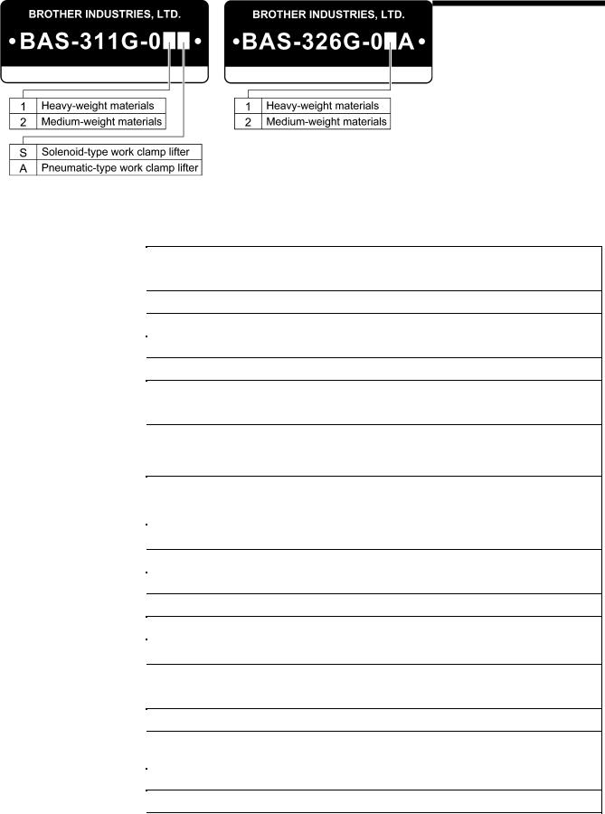
Sewing machine |
Lock stitch, pattern tacking sewing machine (with large shuttle hook) |
|
|
|
|
Stitch formation |
Single needle lock stitch |
|
|
|
|
Max. sewing speed |
2,700 rpm |
|
|
|
|
Sewing area (XxY) |
BAS-311G: Max. 130 x 100 mm, BAS-326G: Max. 220 x 100 mm |
|
|
|
|
Feed mechanism |
Intermittent feed, pulse motor drive |
|
|
|
|
Stitch length |
0.05 − 12.7 mm |
|
|
|
|
No. of stitches |
500,000-stitch internal memory (*) |
|
|
|
|
Maximum no. of stitches |
20,000 stitches (per program) |
|
|
|
|
No. of sewing data items |
Internal memory: 512 (*), CF card: 900 |
|
that can be stored |
||
Solenoid specifications: Pulse motor drive method |
||
Work clamp lift method |
||
Pneumatic specifications: Pneumatic method |
||
|
||
Work clamp height |
Solenoid specifications: Max. 25 mm, pneumatic specifications: Max. 30 mm |
|
|
Solenoid specifications: Integrated-type work clamp |
|
2-step work clamp |
||
Pneumatic specifications: Separate-type work clamp |
||
|
||
Intermittent presser foot lift |
22 mm |
|
amount |
||
|
||
Intermittent stroke |
2 − 4.5 mm, 4.5 − 10 mm or 0 (Default setting 3 mm) |
|
|
|
|
Rotary hook |
Double-capacity shuttle hook (standard shuttle hook sold separately) |
|
|
|
|
Wiper device |
Standard equipment |
|
|
|
|
Thread trimmer |
Standard equipment |
|
|
Internal memory (Flash memory), CF card (32, 64, 128, 256 MB) |
|
Data storage method |
||
[Option] 3.5 floppy disk 2HD/1.44MB, 2DD |
||
|
||
User programs |
50 |
|
|
|
|
Cycle programs |
9 |
|
|
|
|
Motor |
550 W AC servo motor |
|
|
Machine head approx. 88 kg, operation panel approx. 0.6 kg |
|
Weights |
||
Control box 14.2 − 16.2 kg (Differs depending on destination) |
||
|
||
|
|
|
Power supply |
Single-phase 100 V/220 V, Three-phase 200 V/220 V/380 V/400 V 400 VA |
|
|
|
|
Air pressure |
0.5 MPa 1.8 l/min. |
|
|
|
* The number of data items and stitches that can be stored will vary depending on the number of stitches in each program.
BAS-311G, BAS-326G |
1 |

2. FUNCTION SETTINGS
2. FUNCTION SETTINGS
2-1. List of special functions when power is turned on
4421Q
5056Q
1 |
Memory switch setting mode (Standard) |
6 |
|
4541Q |
|
|
Refer to the Instruction Manual. |
|
|
|
|
2 |
Memory switch setting mode (Advanced) |
7 |
|
4542Q |
|
|
Refer to “2-3. Memory Switch Setting Method (Advanced)”. |
|
|
|
|
3 |
Data initialization function |
8 |
|
4543Q |
|
|
Refer to the Instruction Manual. |
|
4 |
Error log display function |
9 |
|
4544Q |
|
|
Refer to “2-7. Error history checking method”. |
|
5 |
Input checking function |
10 |
|
4545Q |
|
|
Refer to “2-8. Input checking method”. |
|
Output checking function
4546Q
Refer to “2-9. Output checking method”. Software version display function
4547Q
Refer to “2-10. Software version checking method”. Feed plate installation mode
5057Q
Refer to “7-10-1. Installing the feed plate”. Home position adjustment mode
4548Q
Refer to “7-20. Adjusting the home position”. Needle up stop position adjustment mode
4549Q
Refer to “7-22. Adjusting the needle up stop position”.
2 |
BAS-311G, BAS-326G |
2. FUNCTION SETTINGS
2-2. List of advanced functions
While holding down the TEST key, press the corresponding combination key.
4550Q
1 |
Memory switch setting mode (Standard) |
5 |
|
4489Q |
|
|
Refer to the Instruction Manual. |
|
2 |
Lower thread counter setting mode |
6 |
|
4490Q |
|
|
Refer to the Instruction Manual. |
|
3 |
Production counter setting mode |
7 |
|
4491Q |
|
|
Refer to the Instruction Manual. |
|
4 |
Production counter temporary display function |
8 |
|
When SPEED indicator is illuminated |
|
|
4492Q |
|
|
Refer to the Instruction Manual. |
|
User program setting mode
4493Q
Refer to the Instruction Manual. Parallel movement mode
4551Q
Refer to the Instruction Manual. Stitch counter checking mode
4552Q
Refer to “2-6. Stitch counter checking method”. CF data read/write mode
4553Q
Refer to “3-4. Data read/write mode”.
BAS-311G, BAS-326G |
3 |
2. FUNCTION SETTINGS
2-3. Memory switch setting method (Advanced)
1 |
|
While pressing the TEST key and the SELECT key, turn |
||||
|
All indicators switch off |
on the power switch. |
|
|||
|
|
* |
Keep pressing the TEST key and the SELECT key until |
|||
|
|
|
the model name is displayed and the buzzer beeps |
|||
|
|
|
once. |
|
|
|
|
|
• |
The memory switch number will be displayed in the |
|||
|
|
|
PROGRAM No. display and the setting value for that |
|||
|
|
|
number will be displayed in the menu display. |
|
||
|
Menu indicator switches off |
|
|
|
4449Q 4421Q |
|
|
TEST indicator illuminates |
|
|
|
||
|
|
|
|
|
|
|
2 |
|
Press the |
or |
key to select the memory |
switch |
|
|
|
number. |
|
|
|
|
|
|
Press the |
or |
key to change the setting value. |
||
|
|
|
|
|
|
4554Q |
|
If you would like to display only the numbers of |
While pressing the SELECT key, press the or |
key. |
|||
|
memory switches that have been changed from |
• |
The numbers of memory switches that have been |
|||
|
default settings |
• |
changed from default settings will appear in order. |
|||
|
|
If no memory switches have been changed from their |
||||
|
|
|
default settings, the display will not change and the |
|||
|
|
|
buzzer will beep twice. |
|
||
|
|
|
|
|
|
4555Q |
|
|
|
|
|||
3 |
Ending setting mode |
Press the TEST key. |
|
|||
|
|
• |
The changes will be memorized and the sewing |
|||
|
|
|
machine will switch to home position detection |
|||
|
|
|
standby. |
|
|
|
|
TEST indicator switches off |
|
|
|
|
|
•If you would like to return the setting for a single memory switch to the default setting, press the RESET key while the number for that memory switch is displayed.
•To return the settings for all memory switches to the default settings, keep pressing the RESET key for two or more seconds until the buzzer makes a long beep.
4 |
BAS-311G, BAS-326G |
|
|
|
|
2. FUNCTION SETTINGS |
||
|
|
|
|
|
|
|
|
2-4. List of memory switch settings |
|
|
|||
|
|
|
|
|
|
|
|
No. |
Setting |
|
Setting items |
Initial value |
|
|
range |
|
|
|||
|
|
|
|
|
|
|
|
001 |
Work clamp lift timing after sewing is completed |
ON |
|
||
|
OFF |
|
Lifts at the final stitch position. |
|
||
|
|
ON |
|
Lifts after moving to the home position. |
|
|
|
|
Separate-type |
work clamp drop operation (pneumatic specifications) |
|
|
|
|
002 |
0 |
|
Left and right work clamp drop at the same time. |
0 |
|
|
1 |
|
Work clamp drops in the order left → right. |
|
||
|
|
|
|
|
||
|
|
2 |
|
Work clamp drops in the order right → left. |
|
|
|
|
Work clamp drop operation (solenoid specifications) |
|
|
||
|
|
0 |
|
Analog dropping: Work clamp drops in direct proportion to the pedal depression |
|
|
|
|
|
amount, and sewing starts when the pedal is fully depressed |
|
|
|
|
|
|
|
|
|
|
|
003 |
1 |
|
1st step drop: Work clamp drops when pedal is depressed to the 1st step, and |
2 |
|
|
|
sewing starts when pedal is depressed to the 2nd step |
|
|||
|
|
|
|
|
|
|
|
|
|
|
2nd step drop: Work clamp drops to intermediate height when the pedal is |
|
|
|
|
2 |
|
depressed to the 1st step, and work clamp drops and sewing starts when the |
|
|
|
|
|
|
pedal is depressed to the 2nd step. |
|
|
|
|
Sewing start |
speed |
|
|
|
|
100 |
OFF |
|
The sewing speed for the first 1 − 5 stitches is set by memory switch numbers 151 |
OFF |
|
|
|
− 155. |
|
|||
|
|
|
|
|||
|
|
ON |
|
1st stitch at 400 rpm, 2nd stitch at 400 rpm, 3rd stitch at 600 rpm, 4th stitch at 900 |
|
|
|
|
|
rpm, 5th stitch at 2,000 rpm |
|
|
|
|
|
|
|
|
|
|
|
|
Single-stitch |
test feed |
|
|
|
|
|
OFF |
|
Test feed starts when the foot switch (start switch) is depressed, and it continues |
|
|
|
|
|
automatically until the final stitch. |
|
|
|
|
|
|
|
|
|
|
|
200 |
|
|
Test feed is carried out one stitch at a time when the foot switch (start switch) is |
OFF |
|
|
|
|
depressed (feed becomes continuous if the foot switch [start switch] is |
|
||
|
|
|
|
|
|
|
|
|
ON |
|
continuously depressed). |
|
|
|
|
|
|
In addition, when the TEST indicator is illuminated, test feeding will move forward |
|
|
|
|
|
|
one stitch at a time when the machine pulley is turned by hand. |
|
|
|
300 |
Production counter display |
OFF |
|
||
|
OFF |
|
Lower thread counter display |
|
||
|
|
ON |
|
Production counter display |
|
|
|
400 |
User programs |
|
|
OFF |
|
|
OFF |
|
Disabled |
|
||
|
|
ON |
|
User program mode is enabled. |
|
|
|
401 |
Cycle programs |
|
OFF |
|
|
|
OFF |
|
Disabled |
|
||
|
|
ON |
|
When sewing user programs, the set programs are sewn in numeric order. |
|
|
|
402 |
Maximum reduction ratio (mm display) (*1) |
OFF |
|
||
|
OFF |
|
Displayed as %. |
|
||
|
|
ON |
|
Displayed as mm. |
|
|
|
|
Split mode selection |
|
|
||
|
403 |
0 |
|
Continuous split (split menu is disabled before split detection) |
0 |
|
|
1 |
|
Continuous split (split menu is always enabled) |
|
||
|
|
|
|
|
||
|
|
2 |
|
Independent split |
|
|
*1 The mm display may differ slightly from the actual sewing size.
BAS-311G, BAS-326G |
5 |

2. FUNCTION SETTINGS
Work clamp settings
No. |
Setting |
|
Setting items |
Initial value |
range |
|
|||
|
|
|
|
|
|
Work clamp |
operating mode (*2) |
|
|
1(Standard single pedal) Work clamp rises automatically.
2(Single pedal with no automatic work clamp lifter)
Work clamp rises in accordance with foot switch depression amount. (Standard 2 pedal)
3Work clamp rises automatically, and drops in accordance with work clamp switch depression amount
*The left and right order can be changed using memory switch No. 002.
4(2 pedal with no automatic work clamp lifter)
Work clamp lifts while work clamp switch is being depressed. (Left/right work clamp → Intermittent presser foot 2-step work clamp)
5When the work clamp switch is depressed to the 1st step, both the left and right work clamps drop, and when it is depressed to the 2nd step, the intermittent presser foot drops. (Lifting is in the same order.)
(Left and right alternating 2-step work clamp)
6Two-step operation, with left and right order switching for each item sewn. Starts from right → left
(Forward/reverse pedal)
When the start switch is depressed, the work clamp drops and the sewing
7machine starts in that order with forward control, and when the work clamp switch is depressed, the sewing machine reverses and the work clamp lifts.
*The left and right order can be changed using memory switch No. 002.
|
(2-step work clamp using two presses) |
|
|
|
For solenoid specifications (1 pedal) |
|
|
|
When the foot switch is depressed, the work clamp stops in the intermediate |
|
|
050 |
position → work clamp drops → sewing machine starts in that order, and the work |
*3 |
|
clamp lifts when the foot switch is depressed backward. |
|||
|
|
8* The work clamp does not stop in the intermediate position if memory switch No. 003 is set to “1”.
For pneumatic specifications (2 pedal)
When the work clamp switch is depressed, the left work clamp drops → right work clamp drops → both work clamps lift in that order.
* The left and right order can be changed using memory switch No. 002.
(Standard 3 pedal)
For solenoid specifications
The left pedal lowers the work clamp in the intermediate position, the right pedal (center) lowers the work clamp, and the start pedal (right) starts the sewing machine.
9* The work clamp does not stop in the intermediate position if memory switch No. 003 is set to “1”.
For pneumatic specifications
The left pedal raises and lowers the left work clamp, and the right pedal (center) raises and lowers the right work clamp.
The start pedal (right) starts the sewing machine.
(Triple pedal with independent home detection)
10The right pedal (center) is used exclusively for detecting the home position.
The left pedal raises and lowers the left and right work clamps, and the start pedal (right) starts the sewing machine.
(Special triple pedal with independent home detection)
11The right pedal (center) is used exclusively for detecting the home position.
The left pedal raises and lowers the left work clamp, and the start pedal (right) lowers the right work clamp and starts the sewing machine.
*2 |
Allowable setting values by specification |
|
||
|
Pedal specifications |
Solenoid specifications |
|
Pneumatic specifications |
|
1 pedal |
1, 2, 8 |
|
1, 2 |
|
2 pedal |
3, 4 |
|
3, 4, 5, 6, 7, 8 |
|
3 pedal |
9 |
|
9, 10, 11 |
*3 |
Solenoid specifications: 1, Pneumatic specifications: 3 |
|
||
6 |
BAS-311G, BAS-326G |

2. FUNCTION SETTINGS
No. |
Setting |
Setting items |
|
Initial value |
|
range |
|
||||
|
|
|
|
||
051 |
Work clamp |
operation before home position detection |
|
ON |
|
|
OFF |
Work clamp cannot be raised or lowered before home position is detected |
|
||
|
|
ON |
Work clamp can be raised and lowered before home position is detected |
|
|
|
Work clamp |
operation during split programs |
|
|
|
052 |
|
OFF |
Work clamp lifts automatically when sewing pauses due to a split program |
|
OFF |
|
ON |
Work clamp lifts when the foot switch is depressed when sewing pauses due to a |
|||
|
|
|
|||
|
|
split program |
|
|
|
|
|
|
|
|
|
053 |
Time from intermittent presser foot lifting until feed mechanism starts moving |
|
100 |
||
0 |
− 999 |
Units (mS) |
|
||
|
|
|
|||
|
Intermittent |
presser foot drop timing |
|
|
|
|
|
0 |
Presser foot drops when the work clamp switch is depressed, but it does not drop |
|
|
054 |
|
at the feed retract position. |
|
0 |
|
|
|
|
|||
|
1 |
Presser foot drops when the work clamp switch is depressed. |
|
||
|
|
|
|
||
|
|
2 |
Presser foot drops at the sewing start, regardless of the work clamp |
switch |
|
|
|
operation. |
|
|
|
|
|
|
|
|
|
|
Work clamp |
signal valve special output for pneumatic-type work clamp (pneumatic specifications) |
|
||
|
|
0 |
Disabled |
|
|
|
|
|
Valve output is reversed for pneumatic specifications |
|
|
055 |
|
1 |
(Connect the air tubes in reverse so that the work clamp can lift when the power is |
0 |
|
|
|
turned off.) |
|
||
|
|
|
|
|
|
|
|
|
Reverse valve output is output simultaneously for 2-position valve specifications. |
|
|
|
|
2 |
(Right work clamp reverse = Option output No. 4, Left work clamp reverse = |
|
|
|
|
|
Option output No. 5) |
|
|
056 |
Thread winding |
operation before home position is detected |
|
OFF |
|
|
OFF |
Thread winding cannot be carried out before home position is detected. |
|
||
|
|
ON |
Thread winding can be carried out before home position is detected. |
|
|
|
Work clamp |
operation when feed moves to sewing start position after home position is detected |
|
||
|
|
|
Work clamp stays dropped after home position is detected |
|
|
057 |
|
OFF |
Work clamp lifts when pedal is depressed backward (for single pedal) or when |
ON |
|
|
|
work clamp switch is depressed (for 2 pedals) |
|
||
|
|
|
|
|
|
|
|
ON |
Work clamp lifts automatically after home position is detected. |
|
|
|
|
* Disabled when memory switch No. 050 = 2 or 4. |
|
|
|
|
|
|
|
|
|
|
Work clamp |
operation at sewing end |
|
|
|
058 |
|
OFF |
Work clamp lifts automatically at the sewing end |
|
OFF |
|
* Disabled when memory switch No. 050 = 2 or 4. |
|
|||
|
|
|
|
|
|
|
|
ON |
Work clamp does not lift automatically at the sewing end |
|
|
BAS-311G, BAS-326G |
7 |

2. FUNCTION SETTINGS
Sewing machine motor settings
No. |
Setting |
Setting items |
Initial value |
|
range |
||||
|
|
|
||
|
Highest needle |
position stop |
|
|
|
OFF |
Disabled |
|
|
|
|
When the upper shaft stops, the motor operates in reverse to return the needle bar |
|
|
150 |
|
close to its highest position. |
OFF |
|
ON |
(When the motor operates in reverse to raise the needle, the thread take-up will |
|||
|
|
|||
|
stop at a position which is lower than its normal stopping position. As a result, the |
|
||
|
|
|
||
|
|
thread take-up will rise slightly at the sewing start, and this may result in the thread |
|
|
|
|
pulling out under certain conditions.) |
|
|
151 |
1st stitch sewing speed at the sewing start |
4 |
||
4 − 27 |
(Units x100 rpm) |
|||
|
|
|||
152 |
2nd stitch sewing speed at the sewing start |
8 |
||
4 − 27 |
(Units x100 rpm) |
|||
|
|
|||
153 |
3rd stitch sewing speed at the sewing start |
12 |
||
4 − 27 |
(Units x100 rpm) |
|||
|
|
|||
154 |
4th stitch sewing speed at the sewing start |
27 |
||
4 − 27 |
(Units x100 rpm) |
|||
|
|
|||
155 |
5th stitch sewing speed at the sewing start |
27 |
||
4 − 27 |
(Units x100 rpm) |
|||
|
|
|||
156 |
5th last stitch |
sewing speed at the sewing end |
27 |
|
4 − 27 |
(Units x100 rpm) |
|||
|
|
|||
157 |
4th last stitch |
sewing speed at the sewing end |
27 |
|
4 − 27 |
(Units x100 rpm) |
|||
|
|
|||
158 |
3rd last stitch |
sewing speed at the sewing end |
27 |
|
4 − 27 |
(Units x100 rpm) |
|||
|
|
|||
159 |
2nd last stitch |
sewing speed at the sewing end |
12 |
|
4 − 20 |
(Units x100 rpm) |
|||
|
|
|||
|
Piercing force |
boosting operation |
|
|
161 |
OFF |
Disabled |
OFF |
|
ON |
Piercing force boosting operations are carried out when the sewing machine motor |
|||
|
|
|||
|
is locked |
|
||
|
|
|
||
|
Regulation of |
sewing speed changes due to sewing pitch changes |
|
|
|
OFF |
Sewing speed varies depending on sewing pitch of the sewing data |
|
|
162 |
|
Speed is fixed at the minimum sewing speed for the maximum pitch of the sewing |
OFF |
|
ON |
data |
|||
|
|
|||
|
(Set to ON if there may be a problem with sewing speed changes as a result of |
|
||
|
|
|
||
|
|
pitch changes.) |
|
|
163 |
Limits the maximum sewing speed. |
27 |
||
12 − 27 |
(Units x100 rpm) |
|||
|
|
|||
164 |
Thread trimming disabled |
OFF |
||
OFF |
Thread trimming is carried out in accordance with the sewing data. |
|||
|
ON |
All thread trimming operations are disabled. |
|
|
165 |
Highest needle |
position stop angle (Units 2 degree steps) (*4) |
0 |
|
-15 − 0 |
0: Normal needle up position: Needle bar height increases for values in the |
|||
|
negative direction. |
|
||
|
|
|
||
*4 If the setting value becomes to large in the negative direction, error “E110” may be generated at the first sewing start after the power is turned on.
8 |
BAS-311G, BAS-326G |
|
|
|
|
2. FUNCTION SETTINGS |
||
|
|
|
|
|
|
|
|
Feed settings |
|
|
|
|
|
|
No. |
Setting |
Setting items |
Initial value |
|
|
|
range |
|
||||
|
|
|
|
|
||
|
|
Mechanism home position return when sewing is finished |
|
|
||
|
250 |
OFF |
When sewing is finished, the feed plate returns to the start position. |
OFF |
|
|
|
ON |
When sewing is finished, the feed plate moves via the machine home position to |
|
|||
|
|
|
|
|||
|
|
the start position. |
|
|
||
|
|
|
|
|
|
|
|
|
Feed speed |
|
|
|
|
|
|
|
1 |
100 mm/s Slow |
|
|
|
251 |
|
2 |
200 mm/s |
3 |
|
|
|
3 |
300 mm/s |
|
||
|
|
|
|
|
||
|
|
|
4 |
400 mm/s |
|
|
|
|
|
5 |
500 mm/s Fast |
|
|
|
|
High-speed test feeding |
|
|
||
|
|
|
|
Feeding is normally slow, and becomes faster when the foot switch is depressed |
|
|
|
252 |
OFF |
to the 1st step |
OFF |
|
|
|
|
|
(For 2 pedals, it becomes faster when the work clamp switch is depressed.) |
|
||
|
|
|
|
|
|
|
|
|
ON |
Test feeding is at the same speed as sewing. |
|
|
|
|
|
* This does not apply to checking stitch by stitch. |
|
|
||
|
|
|
|
|
|
|
|
|
Home position |
detection method |
|
|
|
|
253 |
OFF |
Depress the foot switch (start switch) while the PROGRAM No. display is flashing. |
OFF |
|
|
|
ON |
Press the special external input switch (EXIN3) while the PROGRAM No. display |
|
|||
|
|
|
|
|||
|
|
is flashing. (Foot switch/start switch are disabled.) |
|
|
||
|
|
|
|
|
|
|
|
|
Movement path from mechanism home position to start position |
|
|
||
|
|
|
0 |
Moves to the start position simultaneously for X and Y, in the order of in front of Y |
|
|
|
|
|
→ middle of X. |
|
|
|
|
|
|
|
|
|
|
|
|
|
1 |
Moves to start position in the order of X start point → Y start point in the order of in |
|
|
|
254 |
|
front of Y → middle of X. |
0 |
|
|
|
|
|
|
|||
|
|
|
2 |
Moves to start position in the order of right edge of X → Y start point → X start |
|
|
|
|
|
point in the order of right edge of X → in front of Y. |
|
|
|
|
|
|
|
|
|
|
|
|
|
3 |
Moves to start position in the order of left edge of X → Y start point → X start point |
|
|
|
|
|
in the order of left edge of X → in front of Y. |
|
|
|
|
|
|
|
|
|
|
|
260 |
Changes the |
overall feed timing |
0 |
|
|
|
-10 |
− 10 |
-10: Early ← 0: Standard → 10: Late |
|
||
|
|
|
|
|||
|
261 |
Changes the |
feed timing for the 1st stitch at the sewing start |
0 |
|
|
|
-10 |
− 10 |
-10: Early ← 0: Standard → 10: Late |
|
||
|
|
|
|
|||
|
262 |
Changes the |
feed timing for the 2nd stitch at the sewing start |
0 |
|
|
|
-10 |
− 10 |
-10: Early ← 0: Standard → 10: Late |
|
||
|
|
|
|
|||
|
263 |
Changes the |
feed timing for the 3rd stitch at the sewing start |
0 |
|
|
|
-10 |
− 10 |
-10: Early ← 0: Standard → 10: Late |
|
||
|
|
|
|
|||
|
264 |
Changes the |
feed timing for the 3rd stitch before the sewing end |
0 |
|
|
|
-10 |
− 10 |
-10: Early ← 0: Standard → 10: Late |
|
||
|
|
|
|
|||
|
265 |
Changes the |
feed timing for the 2nd stitch before the sewing end |
0 |
|
|
|
-10 |
− 10 |
-10: Early ← 0: Standard → 10: Late |
|
||
|
|
|
|
|||
|
266 |
Changes the |
feed timing for the 1st stitch before the sewing end |
0 |
|
|
|
-10 |
− 10 |
-10: Early ← 0: Standard → 10: Late |
|
||
|
|
|
|
|||
|
|
If the overall |
feed timing (setting for No. 260) is changed from the default value, specify the |
|
|
|
|
267 |
number of applicable stitches. |
0 |
|
||
|
|
0 |
No limit |
|
||
|
|
1 − 99 |
The feed timing returns to the standard feed timing once the specified number of |
|
|
|
|
|
stitches has been sewn. |
|
|
||
|
|
|
|
|
|
|
|
|
Changes feed |
timing standard |
|
|
|
|
|
|
0 |
[Feed start reference] Makes the timing uniform at the start of feed. |
|
|
|
268 |
|
1 |
[Needle up reference] Changes the timing at the start of feed so that the needle |
1 |
|
|
|
zigzagging is even. |
|
|||
|
|
|
|
|
|
|
|
|
|
2 |
[Feed end reference] Makes the timing uniform at the end of feed. |
|
|
|
|
|
3 |
[Linked to speed] Feed timing is uniform even if the sewing speed changes. |
|
|
|
269 |
Adjusts the feed motor output |
0 |
|
||
|
-5 |
− 5 |
-5: Low← 0: Standard → 5: High |
|
||
|
|
|
|
|||
BAS-311G, BAS-326G |
9 |

2. FUNCTION SETTINGS
Operation panel settings
No. |
Setting |
Setting items |
Initial value |
|
range |
||||
|
|
|
||
|
Operation panel changing limitation |
|
||
|
0 |
No limits on changing setting values using the operation panel. |
|
|
|
1 |
Program numbers, XY scale, sewing speed, lower thread counter, work clamp |
|
|
|
height, intermittent height and digital tension values cannot be changed. |
|
||
|
|
|
||
|
2 |
Program numbers, XY scale, sewing speed, work clamp height, intermittent height |
|
|
350 |
and digital tension values cannot be changed. |
0 |
||
|
||||
|
3 |
Program numbers cannot be changed. |
|
|
|
4 |
Program numbers and XY scale settings cannot be changed. |
|
|
|
5 |
Program numbers, XY scale and sewing speed settings cannot be changed. |
|
|
|
6 |
XY scale settings cannot be enlarged. (They can be reduced.) |
|
|
|
7 |
Sewing speed setting cannot be changed. |
|
|
351 |
Changing memory switches |
OFF |
||
OFF |
Allowed |
|||
|
ON |
Forbidden |
|
|
|
Counting method for lower thread counter and production counter |
|
||
352 |
0 |
Counted for each item of sewing data |
0 |
|
1 |
Counted for each thread trimming operation. |
|||
|
|
|||
|
2 |
Counted when sewing data ends or when split stops |
|
|
353 |
Counter timing |
for lower thread counter |
OFF |
|
OFF |
Counted at the end of sewing. |
|||
|
ON |
Counted at the start of sewing. |
|
|
|
Switching program numbers using an external switch |
|
||
354 |
0 |
Disabled |
0 |
|
|
Program number is switched by means of the 5 bits of option input (EXIN6 − |
|||
|
1 − 9 |
EXIN10). |
|
|
|
|
Applicable numbers are: Setting number = 3rd digit, last two digits can be 1 − 31. |
|
|
|
Switches split |
numbers using an external switch |
|
|
355 |
OFF |
Disabled |
OFF |
|
ON |
Split number is switched by means of the 5 bits of option input (EXIN6 − EXIN10). |
|||
|
|
|||
|
Applicable numbers are 1 − 31 (only enabled for independent split mode) |
|
||
|
|
|
||
User program settings |
|
|
||
No. |
Setting |
Setting items |
Initial value |
|
range |
||||
|
|
|
||
|
Moving to start |
point when switching user programs |
|
|
450 |
OFF |
Feed moves to the start point after starting and switching. |
OFF |
|
ON |
Feed moves to the next sewing start point at the same time as the user program |
|||
|
|
|||
|
switches. |
|
||
|
|
|
||
452 |
Limitations on |
changing settings for user programs |
OFF |
|
OFF |
No limit |
|||
|
ON |
User program contents cannot be changed. |
|
|
10 |
BAS-311G, BAS-326G |

|
|
|
2. FUNCTION SETTINGS |
||
|
|
|
|
|
|
|
Data editing settings |
|
|
|
|
|
No. |
Setting |
Setting items |
Initial value |
|
|
range |
|
|||
|
|
|
|
|
|
|
460 |
Sewing area |
limit in X direction [Units mm] |
|
|
|
0 − 130 |
BAS-311G setting value |
130 |
|
|
|
|
0 − 220 |
BAS-326G setting value |
220 |
|
|
461 |
Sewing area |
limit in Y direction |
|
|
|
0 − 100 |
[Units mm] |
100 |
|
|
|
|
|
|||
|
|
Enlargement/reduction reference point |
|
|
|
|
462 |
0 |
Center of sewing frame |
0 |
|
|
1 |
Sewing start point |
|
||
|
|
|
|
||
|
|
2 |
Center of pattern |
|
|
|
463 |
Enlargement/reduction for bar tacking |
OFF |
|
|
|
OFF |
Bar tacking stitches (pitch approx. 1 mm or less) cannot be enlarged or reduced. |
|
||
|
|
ON |
Bar tacking stitches (pitch approx. 1 mm or less) are also enlarged or reduced. |
|
|
|
|
Enlargement/reduction ratio in XY directions |
|
|
|
|
464 |
OFF |
Disabled |
OFF |
|
|
ON |
Enlargement/reduction ratio setting is the same for X and Y |
|
||
|
|
|
|
||
|
|
(Disabled for user programs) |
|
|
|
|
|
|
|
|
|
|
|
Storing parallel |
movement amount for sewing pattern |
|
|
|
465 |
OFF |
Initialized when program number or enlargement/reduction ratio is changed and |
OFF |
|
|
when power is turned off. |
|
|||
|
|
|
|||
|
|
ON |
Initialized when program number or enlargement/reduction ratio is changed but not |
|
|
|
|
when power is turned off. |
|
|
|
|
|
|
|
|
|
|
|
Reading sewing data from eternal media into internal memory |
|
|
|
|
|
0 |
[Normal mode] Programs are copied one by one into internal memory. |
|
|
|
|
|
[Overwrite mode] Sewing data is overwritten into the temporary buffer area. |
|
|
|
|
1 |
If sewing data with the same program number already exists in internal memory, it |
|
|
|
466 |
|
is deleted. |
0 |
|
|
|
[Assignment mode] Sewing data is overwritten into the temporary buffer area. |
|
||
|
|
|
If sewing data with the same program number already exists in internal memory, it |
|
|
|
|
2 |
is not deleted, but only the data in the temporary buffer is used. |
|
|
|
|
(If sewing data with the same program number already exists in internal memory |
|
|
|
|
|
|
|
|
|
|
|
|
and the setting is changed to “0” or “1”, the data in the temporary buffer will be |
|
|
|
|
|
cleared.) |
|
|
|
|
Changing gear |
ratio correction method when reading from a 2DD floppy disk. |
|
|
|
|
0 |
Automatic conversion as specified by sewing machine model. |
|
|
|
467 |
(For the BAS-311G, data is read as BAS-311A data and then converted.) |
0 |
|
|
|
|
|
|||
|
1 |
BAS-311A data is read. |
|
||
|
|
|
|
||
|
|
2 |
BAS-326A data is read. |
|
|
|
|
3 |
BAS-341A/BAS-342A data is read. |
|
|
|
468 |
Retract point |
switching at parallel movement point |
OFF |
|
|
OFF |
Disabled |
|
||
|
|
ON |
The position moved to by parallel movement is recorded as the retract point. |
|
|
|
Device settings |
|
|
|
|
|
No. |
Setting |
Setting items |
Initial value |
|
|
range |
|
|||
|
|
|
|
|
|
|
550 |
Needle cooler |
device |
OFF |
|
|
OFF |
Disabled |
|
||
|
|
ON |
Needle cooler device is used. (Option output No. 12) |
|
|
|
551 |
Tension release setting at the sewing start |
OFF |
|
|
|
OFF |
Disabled |
|
||
|
|
ON |
Enabled |
|
|
|
552 |
Tension release timing during thread trimming [Units 8 degree steps] |
0 |
|
|
|
-10 − 1 |
-10: Early ← 0: Standard → 1: Late |
|
||
|
|
|
|
||
|
553 |
Thread nipping |
timing (*5) |
2 |
|
|
1 − 4 |
1: Early ← 2: Standard → 4: Late |
|
||
|
|
|
|
||
*5 Not used for the BAS-311G and BAS-326G.
BAS-311G, BAS-326G |
11 |

2. FUNCTION SETTINGS
No. |
Setting |
Setting items |
Initial value |
|
range |
||||
|
|
|
||
554 |
Thread breakage detector |
OFF |
||
OFF |
Disabled |
|||
|
ON |
Fiber-type thread breakage detector used |
|
|
555 |
Thread breakage detector detection sensitivity |
OFF |
||
OFF |
5 stitches at sewing start, 3 stitches while sewing |
|||
|
ON |
10 stitches at sewing start, 3 stitches while sewing |
|
|
|
Inner clamping |
device (Option output No. 13) |
|
|
|
0 |
Disabled |
|
|
|
|
Inner clamping device is used. |
|
|
556 |
1 |
(Retract operation is carried out at the sewing end to prevent interference with the |
0 |
|
|
needle.) |
|||
|
2 |
Inner clamping device is used. (No retract operation at the sewing end.) |
|
|
|
|
Inner clamping device operates for 1/4 of the sewing pattern and returns for the |
|
|
|
3 |
other 3/4. |
|
|
|
|
(No retract operation) |
|
|
|
External wiper |
device |
|
|
557 |
0 |
Disabled |
1 |
|
1 |
Solenoid-type wiper device is used. |
|||
|
|
|||
|
2 |
Pneumatic-type wiper device is used. (Option output No. 2) |
|
|
558 |
External error |
monitoring input |
OFF |
|
OFF |
Disabled |
|||
|
ON |
Enabled (P10, option input No. 13 [AIRSW]) |
|
|
|
Operating indicator output |
|
||
559 |
OFF |
Disabled |
OFF |
|
|
Option output No. 9: Output ON while operating |
|||
|
ON |
Option output No. 10: ON during lower thread conversion and during test mode |
|
|
|
|
Option output No. 11: ON when error is generated |
|
|
|
Automatic ejector (Option output No. 3 output, option input No. 1 = right sensor, input No. 2 = left |
|
||
|
sensor) [Pneumatic specifications] |
|
||
560 |
0 |
Disabled |
0 |
|
1 |
Standard operation |
|||
|
|
|||
|
2 |
Sewing starts when cassette sensor is ON |
|
|
|
3 |
Start switch is enabled even if cassette sensor is OFF. |
|
|
|
Timer from |
sensor detection to sewing start when automatic ejector automatic starting is set |
|
|
561 |
(memory switch No. 560 = 2) [Pneumatic specifications] |
100 |
||
|
0 − 999 |
Time from after the cassette is chucked until automatic starting |
|
|
|
Changes the |
digital tension setting value. |
|
|
562 |
OFF |
Tension number can be changed regardless of the sewing data. |
ON |
|
ON |
Only tension No. 0 and the tension numbers detected in the sewing data can be |
|||
|
|
|||
|
changed. |
|
||
|
|
|
||
563 |
2-step tension |
is possible (When using spring-type main tension) |
OFF |
|
OFF |
Disabled |
|||
|
ON |
2-step tension is used. |
|
|
|
Increases maximum tension release force when using a spring-type main tension |
|
||
|
0 |
Disabled (Tension release is open at the sewing end.) |
|
|
564 |
1 |
Increases the force (Tension release is closed at the sewing end. If tension release |
0 |
|
is open, it will be closed in approximately 5 minutes.) |
||||
|
|
|
||
|
2 |
Increases force to the maximum. (Tension release is closed at the sewing end. If |
|
|
|
tension release is open, it will be closed in approximately 1 minute.) |
|
||
|
|
|
||
|
Thread nipper |
device (*6) |
|
|
565 |
OFF |
Disabled |
OFF |
|
ON |
Thread nipper device installed (Memory switch No. 500 must also be set to ON or |
|||
|
|
|||
|
OFF.) |
|
||
|
|
|
||
*6 Not used for the BAS-311G and BAS-326G. |
|
|||
12 |
BAS-311G, BAS-326G |

|
|
|
2. FUNCTION SETTINGS |
||
|
|
|
|
|
|
|
Error processing settings |
|
|
||
|
No. |
Setting |
Setting items |
Initial value |
|
|
range |
|
|||
|
|
|
|
|
|
|
|
Error release |
method when operation has stopped |
|
|
|
650 |
0 |
Press the RESET key. |
0 |
|
|
1 |
Press the RESET key or the STOP switch. |
|
||
|
|
|
|
||
|
|
2 |
Press the RESET key or input a signal from the external switch (EXIN3). |
|
|
|
|
Needle stop |
position when sewing is interrupted by the STOP switch |
|
|
|
651 |
0 |
Needle stops in the down position. |
0 |
|
|
1 |
Needle stops in the up position. |
|
||
|
|
|
|
||
|
|
2 |
Needle stops in the up position after thread trimming. |
|
|
|
652 |
Thread trimming operation when sewing is paused |
OFF |
|
|
|
OFF |
Thread trimming is carried out when the pause is canceled. |
|
||
|
|
ON |
Thread trimming is not carried out when the pause is canceled. |
|
|
|
653 |
Resuming sewing after sewing is paused |
OFF |
|
|
|
OFF |
STOP switch → RESET key → key → Sewing starts |
|
||
|
|
ON |
STOP switch → RESET key → Sewing starts |
|
|
|
655 |
Disables the |
needle up stop position monitoring sensor |
OFF |
|
|
OFF |
Sensor is enabled and needle up stop position errors [E110] are detected. |
|
||
|
|
ON |
Disabled |
|
|
|
|
Home position |
return when sewing is paused |
|
|
|
656 |
OFF |
Mechanism moves to home position and then moves to sewing start position. |
OFF |
|
|
ON |
Mechanism steps back to the sewing start position along the sewing path without |
|
||
|
|
|
|
||
|
|
moving to the home position. |
|
|
|
|
|
|
|
|
|
|
Maintenance settings |
|
|
|
|
|
No. |
Setting |
Setting items |
Initial value |
|
|
range |
|
|||
|
|
|
|
|
|
|
|
Run-in operation mode |
|
|
|
|
|
0 |
Disabled |
|
|
|
|
|
While the foot switch is being depressed, the work clamp moves up and down |
|
|
|
|
1 |
once and then continuous operation starts. |
|
|
|
750 |
|
(Work clamp does not move up or down if memory switch No. 050 = 2 or 4) |
0 |
|
|
|
While the foot switch is being depressed, the work clamp moves up and down |
|
||
|
|
2 |
twice and then continuous operation starts. |
|
|
|
|
|
(Work clamp does not move up or down if memory switch No. 050 = 2 or 4) |
|
|
|
|
|
While the foot switch is being depressed, the work clamp moves up and down |
|
|
|
|
3 |
three times and then continuous operation starts. |
|
|
|
|
|
(Work clamp does not move up or down if memory switch No. 050 = 2 or 4) |
|
|
|
751 |
Run-in operation cycle time adjustment timer |
20 |
|
|
|
0 − 255 |
Units [x10 ms] |
|
||
|
|
|
|
||
|
752 |
00 − 99 |
Sewing machine ID code |
00 |
|
|
Sewing data specified on CF card |
|
|||
|
|
|
|
|
|
|
755 |
Reading/writing |
sewing data for old models |
OFF |
|
|
OFF |
Only compatible with floppy disks. |
|
||
|
|
ON |
Reading and writing using CF cards is possible in data read/write mode. |
|
|
|
756 |
Main shaft angle display mode |
OFF |
|
|
|
OFF |
Disabled |
|
||
|
|
ON |
Main shaft angle is displayed when sewing machine starts. |
|
|
|
Specifications and destination settings |
|
|
||
|
No. |
Setting |
Setting items |
Initial value |
|
|
range |
|
|||
|
|
|
|
|
|
|
|
Specification |
code setting |
|
|
|
|
(This memory switch does not return to the initial value when all settings are reset.) |
|
|
|
|
|
0 |
Specifications at the time of shipment from the factory |
|
|
|
850 |
(Specifications shown on the model plate on the machine head) |
0 |
|
|
|
|
|
|||
|
|
1 |
Heavy-weight material specifications |
|
|
|
|
2 |
Medium-weight material specifications |
|
|
|
|
3 |
Extra heavy-weight material specifications |
|
|
BAS-311G, BAS-326G |
13 |
2. FUNCTION SETTINGS
Unique machine settings
No. |
Setting |
Setting items |
Initial value |
|
range |
||||
|
|
|
||
950 |
Automatic start for extended option output No. 1 |
OFF |
||
OFF |
Disabled |
|||
|
ON |
Sewing machine starts when extended option output No. 1 is ON. |
|
|
|
Program number output |
|
||
951 |
OFF |
Disabled |
OFF |
|
ON |
When the last two digits of the program number are 1 to 15, the program number |
|||
|
|
|||
|
is output in 4 bits to extended option output 4 − 7. |
|
||
|
|
|
||
2-5. Setting the work clamp mode
Combinations of memory switch settings can be used to switch the work clamp operating mode to any one of the following modes.
<Solenoid specifications, single pedal standard operations>
|
|
Operating mode |
|
Memory switch setting |
||||
Drop operation |
Automatic work |
After home position detection |
After sewing start |
003 |
050 |
057 |
058 |
|
clamp lifting |
||||||||
|
|
|
|
|
|
|
||
|
|
Automatic lift |
Automatic lift |
0 |
1 |
ON |
OFF |
|
Analog drop |
Yes |
Dropped |
0 |
1 |
ON |
ON |
||
|
||||||||
Dropped (*) |
Automatic lift |
0 |
1 |
OFF |
OFF |
|||
|
||||||||
|
|
Dropped (*) |
0 |
1 |
OFF |
ON |
||
|
|
|
||||||
|
No |
Dropped (*) |
Dropped (*) |
0 |
2 |
− |
− |
|
|
|
Automatic lift |
Automatic lift |
1 |
1 |
ON |
OFF |
|
|
Yes |
Dropped |
1 |
1 |
ON |
ON |
||
|
|
|||||||
1st step drop |
Dropped (*) |
Automatic lift |
1 |
1 |
OFF |
OFF |
||
|
||||||||
|
|
Dropped (*) |
1 |
1 |
OFF |
ON |
||
|
|
|
||||||
|
No |
Dropped (*) |
Dropped (*) |
1 |
2 |
− |
− |
|
|
|
Automatic lift |
Automatic lift |
2 |
1 |
ON |
OFF |
|
|
Yes |
Dropped |
2 |
1 |
ON |
ON |
||
|
|
|||||||
2nd step drop |
Dropped (*) |
Automatic lift |
2 |
1 |
OFF |
OFF |
||
|
||||||||
|
|
Dropped (*) |
2 |
1 |
OFF |
ON |
||
|
|
|
||||||
|
No |
Dropped (*) |
Dropped (*) |
2 |
2 |
− |
− |
|
(*) If memory switch No. 057 is OFF, the work clamp will lift when the pedal is depressed backward.
<Solenoid specifications, single pedal sequence operation>
|
|
Operating mode |
|
Memory switch setting |
||||
Drop operation |
Automatic work |
After home position detection |
After sewing start |
003 |
050 |
057 |
058 |
|
clamp lifting |
||||||||
|
|
|
|
|
|
|
||
|
|
Automatic lift |
Automatic lift |
1 |
8 |
ON |
OFF |
|
1st step drop |
Yes |
Dropped (*) |
1 |
8 |
ON |
ON |
||
|
||||||||
Dropped (*) |
Automatic lift |
1 |
8 |
OFF |
OFF |
|||
|
|
|||||||
|
|
Dropped (*) |
1 |
8 |
OFF |
ON |
||
|
|
|
||||||
|
|
Automatic lift |
Automatic lift |
2 |
8 |
ON |
OFF |
|
2nd step drop |
Yes |
Dropped (*) |
2 |
8 |
ON |
ON |
||
|
||||||||
Dropped (*) |
Automatic lift |
2 |
8 |
OFF |
OFF |
|||
|
|
|||||||
|
|
Dropped (*) |
2 |
8 |
OFF |
ON |
||
|
|
|
||||||
(*) Work clamp lifts when pedal is depressed backward.
14 |
BAS-311G, BAS-326G |
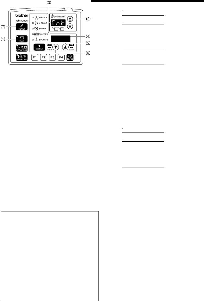
2. FUNCTION SETTINGS
<Pneumatic specifications, 2 pedal standard operations> |
|
Memory switch setting |
|
|||||||||||
|
|
|
|
|
Operating mode |
|
|
|
||||||
Work clamp operation |
After home position |
After sewing start |
|
002 |
|
050 |
057 |
058 |
||||||
detection |
|
|
||||||||||||
|
|
|
|
|
|
|
Work |
clamp |
drop |
|
|
|
||
|
|
|
|
|
|
Automatic lift |
Automatic lift |
3 |
ON |
OFF |
||||
Work clamp lifts automatically |
|
sequence selection |
|
|
|
|||||||||
Dropped |
3 |
ON |
ON |
|||||||||||
|
0: Left and right |
|
||||||||||||
and |
drops |
when the |
work |
|
|
simultaneously |
|
|
|
|
||||
|
Automatic lift |
|
3 |
OFF |
OFF |
|||||||||
clamp switch is depressed. |
|
|
||||||||||||
Dropped |
1: Left → Right |
|
||||||||||||
|
|
|
|
|
|
Dropped |
|
3 |
OFF |
ON |
||||
|
|
|
|
|
|
|
2: Right → Left |
|
||||||
Work clamp rises while work |
Dropped |
Dropped |
|
− |
|
4 |
− |
− |
||||||
clamp switch is depressed |
|
|
||||||||||||
|
|
|
|
|
|
|
|
|||||||
|
|
|
|
|
|
|
|
|
|
|||||
Work clamp switch |
|
Automatic lift |
Automatic lift |
|
|
|
5 |
ON |
OFF |
|||||
1st step: Both left and right |
|
|
|
|
|
|
|
|||||||
Dropped |
|
|
|
5 |
ON |
ON |
||||||||
work clamps drop |
|
|
|
|
− |
|
||||||||
2nd step: Intermittent presser |
|
Automatic lift |
|
|
5 |
OFF |
OFF |
|||||||
|
|
|
|
|||||||||||
foot drops |
|
|
|
Dropped |
|
|
|
|||||||
|
|
|
|
|
|
|
|
|
|
|||||
|
|
|
Dropped |
|
|
|
5 |
OFF |
ON |
|||||
Lifting is simultaneous |
|
|
|
|
|
|||||||||
Work clamp drop sequence at |
Automatic lift |
Automatic lift |
|
|
|
6 |
ON |
OFF |
||||||
|
|
|
|
|
|
|
||||||||
work clamp switch 1st and |
Dropped |
|
|
|
6 |
ON |
ON |
|||||||
|
|
|
|
|||||||||||
2nd |
steps |
alternates |
each |
|
|
|
− |
|
|
|
|
|||
|
Automatic lift |
|
|
6 |
OFF |
OFF |
||||||||
time an article is sewn. |
|
Dropped |
|
|
|
|||||||||
Initially right → left |
|
Dropped |
|
|
|
6 |
OFF |
ON |
||||||
|
|
|
|
|
||||||||||
|
|
|
|
|
|
|
|
|
|
|||||
|
|
|
|
|
|
|
|
|
||||||
<Pneumatic specifications, 2 pedal sequence operation> |
|
Memory switch setting |
|
|||||||||||
|
|
|
|
|
Operating mode |
|
|
|
||||||
Work clamp operation |
After home position |
After sewing start |
|
002 |
|
050 |
057 |
058 |
||||||
detection |
|
|
||||||||||||
|
|
|
|
|
|
|
Work |
clamp |
drop |
|
|
|
||
When |
start |
switch |
is |
Automatic lift |
Automatic lift |
7 |
ON |
OFF |
||||||
depressed, work clamp drops |
|
sequence selection |
|
|
|
|||||||||
Dropped |
7 |
ON |
ON |
|||||||||||
|
0: Left and right |
|
||||||||||||
→ sewing starts |
|
|
|
|
simultaneously |
|
|
|
|
|||||
|
|
|
Automatic lift |
|
7 |
OFF |
OFF |
|||||||
Lifts |
in |
reverse |
order |
using |
|
|
||||||||
Dropped |
1: Left → Right |
|
||||||||||||
work clamp switch |
|
|
|
|
|
|
||||||||
|
Dropped |
|
7 |
OFF |
ON |
|||||||||
|
|
2: Right → Left |
|
|||||||||||
|
|
|
|
|
|
|
|
|||||||
|
|
|
|
|
|
|
Automatic lift |
Work |
clamp |
drop |
5 |
ON |
OFF |
|
Work clamp switch |
|
Automatic lift |
|
sequence selection |
|
|
|
|||||||
|
Dropped |
5 |
ON |
ON |
||||||||||
Left (right) work clamp → |
|
0: Left and right |
|
|||||||||||
Right (left) work clamp → |
|
Automatic lift |
simultaneously |
|
5 |
OFF |
OFF |
|||||||
Both work clamps lift |
|
Dropped |
|
1: Left → Right |
|
|
|
|
||||||
|
Dropped |
|
5 |
OFF |
ON |
|||||||||
|
|
|
|
|
|
|
2: Right → Left |
|
||||||
2-6. Stitch counter checking method
5058Q
1.While holding down the TEST key (1), press the  key
key
(2).
“Cnt” will be displayed in the PROGRAM No. display (3), and the cumulative number of stitches will be displayed in the menu display (4) in units of 100,000 stitches.
(While the  key (5) is being pressed, the cumulative number of stitches will be displayed in units of 100 stitches in all 7 digits of the PROGRAM No. display and the menu display (4).)
2.When the TEST key (1) is pressed, the display will return to the normal display.
<Clearing the cumulative number of stitches>
1.When “Cnt” is displayed, press the  key (6). The cumulative number of stitches will change to “0000” and the display will flash.
2.Press the RESET key (7) for two seconds or more. (The cumulative number of stitches “0000” will stop flashing and illuminate, and the setting will be cleared. )
3.When the TEST key (1) is pressed, the display will return to the normal display.
BAS-311G, BAS-326G |
15 |
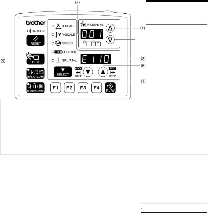
2. FUNCTION SETTINGS
2-7. Error history checking method
The past error history can be checked by the following procedure.
4564Q
TEST indicator illuminates, Menu indicator switches off
1.While pressing the  key (1), turn on the power switch.
*Keep pressing the  key (1) until the model name is displayed and the buzzer beeps once.
The error history sequence number will be displayed in the PROGRAM No. display (2) and the error code will be displayed in the menu display (3).
2.Press the  or
or  key (4) to switch the error history sequentially.
3.When the TEST key (5) is pressed, the display will return to the normal display and the sewing machine will change to home position standby.
<Display example> |
|
Menu display (3) |
Details |
PROGRAM No. display (2) |
|
If there is no error history |
[000] |
[E − − −] |
Error [E110] is displayed first. |
[001] |
[E110] |
•While the  key (6) is being pressed, the COUNTER indicator will illuminate and the stitch number counter value at the point where the error occurred will be displayed in the PROGRAM No. display (2) and the menu display (3) in units of 100 stitches.
16 |
BAS-311G, BAS-326G |
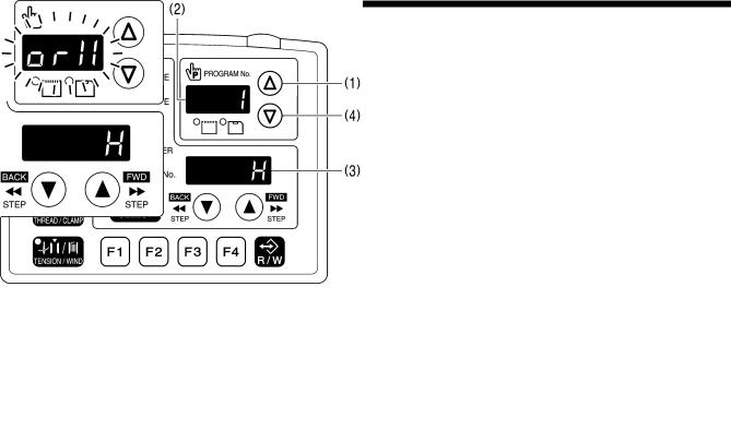
2. FUNCTION SETTINGS
2-8. Input checking method
Use this to check for any malfunctions of the operation panel keys, circuit boards or sensors, and for checking for broken cords and for adjusting sensor positions.
You can check whether the CPU is correctly reading the signals from keys and sensors.
4565Q |
|
|
|
4566Q |
|
|
|
||
|
|
|
||
|
|
|
||
|
|
|
||
|
|
|
|
|
1.While pressing the  key (1), turn on the power switch.
* Keep pressing the  key (1) until the model name is displayed and the buzzer beeps once.
The check code will be displayed in the PROGRAM No. display (2), and the input status will be displayed in the menu display (3).
2.Press the  key (1) or
  key (4) to select the desired check code.
If no operations are carried out for 5 seconds after a check code has been selected, the check code and the abbreviated input name will flash alternately in the PROGRAM No. display (2).
3.Refer to the input check list for key and sensor responses.
4.To return to normal operation, turn off the power switch and then turn it back on again.
<Input check list>
PROGRAM No. display |
Menu display |
Check item and checking method |
|||||
Check code |
Name |
Input status |
|||||
|
|||||||
[ |
1] |
[orX] |
[ |
H] / [ |
L] |
X-axis motor home position sensor signal |
|
Move the feed mechanism by hand in the X direction. |
|||||||
|
|
|
|
|
|
||
[ |
2] |
[EnX] |
[-999] − [999] |
X-axis motor encoder counter value |
|||
Move the feed mechanism by hand in the X direction. |
|||||||
|
|
|
|
|
|
||
[ |
3] |
[orY] |
[ |
H] / [ |
L] |
Y-axis motor home position sensor signal |
|
Move the feed mechanism by hand in the Y direction. |
|||||||
|
|
|
|
|
|
||
[ |
4] |
[EnY] |
[-999] − [999] |
Y-axis motor encoder counter value |
|||
Move the feed mechanism by hand in the Y direction. |
|||||||
|
|
|
|
|
|
||
[ |
5] |
[orP] |
[ |
H] / [ |
L] |
Work clamp motor home position sensor signal |
|
Raise the work clamp by hand. |
|||||||
|
|
|
|
|
|
||
[ |
6] |
[EnP] |
[-999] − [999] |
Work clamp motor encoder counter value |
|||
Raise the work clamp by hand. |
|||||||
|
|
|
|
|
|
||
[ |
7] |
[Enn] |
[ |
0] − [180] |
Upper shaft 180 degree rotation signal |
||
Turn the pulley by hand. |
|||||||
|
|
|
|
|
|
||
BAS-311G, BAS-326G |
17 |

2. FUNCTION SETTINGS
PROGRAM No. display |
Menu display |
|
Check item and checking method |
|
|
|
||||
Check code |
Name |
|
Input status |
|
|
|
|
|||
|
|
|
|
|
|
|||||
[ |
8] |
[ UP] |
[ |
on] / [ oFF] |
Needle up signal |
|
|
|
||
Turn the pulley by hand. |
|
|
|
|||||||
|
|
|
|
|
|
|
|
|
||
[ |
9] |
[ dn] |
[ |
on] / [ oFF] |
Needle drop signal |
|
|
|
||
Turn the pulley by hand. |
|
|
|
|||||||
|
|
|
|
|
|
|
|
|
||
[ 10] |
[voL] |
[ |
0] − [ 300] |
Power supply voltage |
|
|
|
|||
Displayed as % |
|
|
|
|||||||
|
|
|
|
|
|
|
|
|
||
|
|
|
|
|
|
Operation panel input check |
|
|
|
|
[ 11] |
[PnL] |
|
[*] / [ oFF] |
While a key is being pressed, the name of the key will be |
||||||
|
|
|
|
|
|
displayed. |
|
|
|
|
|
|
|
|
*ON display |
|
Key name |
|
|
|
|
|
|
|
|
[rESt] |
RESET key |
|
|
|
|
|
|
|
|
|
[tESt] |
TEST key |
|
|
|
|
|
|
|
|
|
[tHrE] |
THREAD/CLAMP key |
|
|
|
||
|
|
|
|
[ tEn] |
TENSION/WIND key |
|
|
|
||
|
|
|
|
[SELE] |
SELECT key |
|
|
|
|
|
|
|
|
|
[UP-M] |
key |
|
|
|
|
|
|
|
|
|
[dn-M] |
key |
|
|
|
|
|
|
|
|
|
[ |
F1] |
Function key F1 |
|
|
|
|
|
|
|
|
[ |
F2] |
Function key F2 |
|
|
|
|
|
|
|
|
[ |
F3] |
Function key F3 |
|
|
|
|
|
|
|
|
[ |
F4] |
Function key F4 |
|
|
|
|
|
|
|
|
[ |
CF] |
R/W key |
|
|
|
|
[ 12] |
[FtA] |
[ |
0] − [ 255] |
Foot switch analog value (Single pedal specifications) |
|
|
||||
Depress the foot switch. |
|
|
|
|||||||
|
|
|
|
|
|
|
|
|
||
[ 13] |
[CL1] |
[ |
on] / [ oFF] |
Work clamp 1st step (2 pedal specifications) |
|
|
|
|||
Depress the foot switch to the 1st step. |
|
|
|
|||||||
|
|
|
|
|
|
|
|
|
||
[ 14] |
[CL2] |
[ |
on] / [ oFF] |
Work clamp 2nd step (2 pedal specifications) |
|
|
|
|||
Depress the foot switch to the 2nd step. |
|
|
|
|||||||
|
|
|
|
|
|
|
|
|
||
[ 15] |
[Stt] |
[ |
on] / [ oFF] |
Start switch (2 pedal specifications) |
|
|
|
|||
Depress the foot switch to the 2nd step. |
|
|
|
|||||||
|
|
|
|
|
|
|
|
|
||
|
|
|
|
[− − on] |
STOP switch |
|
|
|
|
|
[ 16] |
[EMC] |
|
[on − −] |
Press the STOP switch. |
|
|
|
|||
|
|
|
|
[− − − −] |
|
|
|
|
|
|
[ 17] |
[HEd] |
[ |
on] / [ oFF] |
Machine head switch |
|
|
|
|||
Tilt back the machine head. |
|
|
|
|||||||
|
|
|
|
|
|
|
|
|
||
[ 18] |
[EXE] |
[ |
on] / [ oFF] |
External input error detection (IN13) |
|
|
|
|||
|
|
|
|
|
|
Thread nipper hope position sensor (IN14) (*1) |
|
|
|
|
|
|
|
|
|
|
Press the |
key to move the thread nipper in the home position |
|||
[ 19] |
[CAH] |
[ |
on] / [ oFF] |
direction. |
|
|
|
|
||
|
|
|
|
|
|
Press the |
key to move the thread nipper |
in |
the |
retract |
|
|
|
|
|
|
direction. |
|
|
|
|
|
|
|
|
|
|
Thread nipper retract sensor (IN15) (*1) |
|
|
|
|
|
|
|
|
|
|
Press the |
key to move the thread nipper in the home position |
|||
[ 20] |
[rEL] |
[ |
on] / [ oFF] |
direction. |
key to move the thread nipper |
in |
the |
retract |
||
|
|
|
|
|
|
Press the |
||||
|
|
|
|
|
|
direction. |
|
|
|
|
[ 21] |
[in1] |
[ |
on] / [ oFF] |
Option input (IN1) |
|
|
|
|||
[ 22] |
[in2] |
[ |
on] / [ oFF] |
Option input (IN2) |
|
|
|
|||
[ 23] |
[in3] |
[ |
on] / [ oFF] |
Option input (IN3) |
|
|
|
|||
[ 24] |
[in4] |
[ |
on] / [ oFF] |
Option input (IN4) |
|
|
|
|||
[ 25] |
[in5] |
[ |
on] / [ oFF] |
Option input (IN5) |
|
|
|
|||
[ 26] |
[rot] |
[ |
on] / [ oFF] |
Option input (IN11) |
|
|
|
|||
[ 27] |
[Fib] |
[ |
on] / [ oFF] |
Fiber-type thread breakage detection [Option compatibility] |
||||||
*1 Not used for the BAS-311G and BAS-326G.
18 |
BAS-311G, BAS-326G |

2. FUNCTION SETTINGS
PROGRAM No. display |
Menu display |
Check item and checking method |
||
Check code |
Name |
|
Input status |
|
|
|
|||
[ 28] |
[Por] |
[ |
on] / [ oFF] |
Work clamp home position sensor |
[ 29] |
[Xor] |
[ |
on] / [ oFF] |
X-feed home position sensor |
[ 30] |
[Yor] |
[ |
on] / [ oFF] |
Y-feed home position sensor |
[ 31] |
[in6] |
[ |
on] / [ oFF] |
Option input (IN6) |
[ 32] |
[in7] |
[ |
on] / [ oFF] |
Option input (IN7) |
[ 33] |
[in8] |
[ |
on] / [ oFF] |
Option input (IN8) |
[ 34] |
[in9] |
[ |
on] / [ oFF] |
Option input (IN9) |
[ 35] |
[in10] |
[ |
on] / [ oFF] |
Option input (IN10) |
BAS-311G, BAS-326G |
19 |
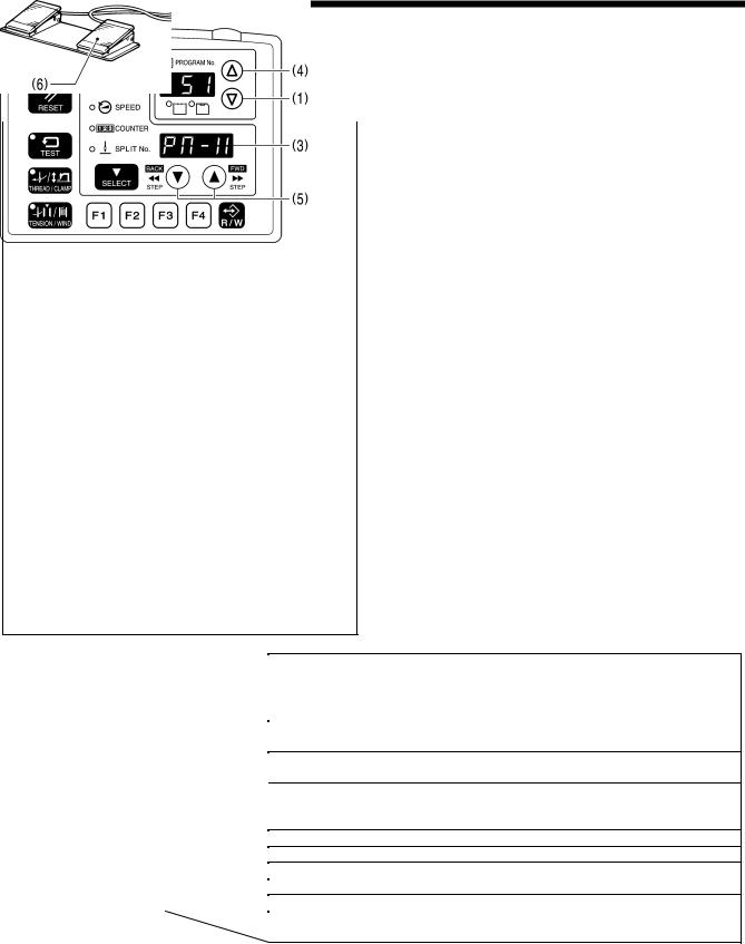
2. FUNCTION SETTINGS
2-9. Output checking method
Use this to check for any malfunctions of the circuit boards, and for checking for problems with drive mechanisms and broken cords.
You can check whether the signals being output by the CPU are driving the mechanisms correctly.
|
|
|
4567Q |
1. |
While pressing the key (1), turn on the power switch. |
||
|
|
|
|
|
|
* Keep pressing the |
key (1) until the model name is |
|
|
|
|
|
|
displayed and the buzzer beeps once. |
|
|
|
|
|
|
|
The check code will be displayed in the PROGRAM No. |
|
|
|
|
|
|
|
display (2), and the abbreviated name of the output will |
|
|
|
|
|
|
|
be displayed in the menu display (3). |
|
|
|
|
|
|
2. |
Press the key (4) or |
key (1) to select the desired |
|
|
|
|
|
|
check code. |
|
|
|
|
|
|
3. |
The operations for check codes 51 to 54 can be |
|
|
|
|
|
|
|
checked by pressing the |
or key (5). |
|
|
|
|
|
4. |
For check codes 55 and onward, depress the foot |
|
|
|
|
|
|
|
switch to the 2nd step. |
|
|
|
|
|
|
|
(If using a two-pedal foot switch, lower the work clamp |
|
|
|
|
|
|
|
before depressing the start switch (6). ) |
|
|
|
|
|
|
|
|
|
|
|
|
|
|
|
The corresponding operation for the check code will |
|
|
|
|
|
|
|
be carried out while the foot switch is being |
|
|
|
|
|
|
|
depressed (while the foot switch has been depressed |
|
2nd step |
|
|
|
|
|
once for check code 60). |
|
|
|
|
|
|
|||
|
|
|
|
|
|
||
|
|
|
|
5. |
To return to normal operation, turn off the power switch |
||
|
|
|
|
|
|
and then turn it back on again. |
|
|
|
|
|
|
|
|
|
|
|
|
|
|
|
|
|
|
|
|
|
|
|
|
|
4441Q 4953Q
PROGRAM No. display |
Menu display |
Check code |
Name |
[ 51] |
[PM-X] |
|
|
[ 52] |
[PM-y] |
|
|
[ 53] |
[PM-F] |
|
|
[ 54] |
[CAtH] |
|
|
[ 55] |
[CL-r] |
[ 56] |
[CL-L] |
[ 57] |
[Foot] |
[ 58] |
[FLiP] |
[ 59] |
[CooL] |
[ 60] |
|
|
|
Operating details
When the  key is pressed, the work clamp moves to the left. When the
  key is pressed, the work clamp moves to the right. When the
  key is pressed, the work clamp moves forward. When the
  key is pressed, the work clamp moves back. When the
  key is pressed, the work clamp lifts.
When the  key is pressed, the work clamp drops.
When the  key is pressed, the thread nipper moves to the home position. When the
  key is pressed, the thread nipper moves to the retract position. [Option compatibility]
Right clamp valve turns on. (OUT16) (*1) Left clamp valve turns on. (OUT15) (*1)
Intermittent presser foot valve turns on. (OUT14) (*1) Inner clamping device valve turns on. (OUT13) (*1) Needle cooler valve turns on. (OUT12) (*1)
The panel LEDs illuminate in order, and then the seven segments of the PROGRAM No. display and the menu display illuminate one by one.
*1 Applies for pneumatic specifications when corresponding devices are installed.
20 |
BAS-311G, BAS-326G |

2. FUNCTION SETTINGS
PROGRAM No. display |
Menu display |
Operating details |
|
Check code |
Name |
||
Turns on the thread trimming solenoid. |
|||
[ 61] |
[ CUt] |
||
|
|
Turns on the tension release solenoid/digital tension solenoid. |
|
[ 62] |
[ rEL] / [dtEn] |
(*2) |
|
However, in the case of digital tension, the solenoid turns on at the tension |
|||
|
|
||
|
|
that has been set. |
|
[ 63] |
[ WiP] |
Turns on the thread wiper solenoid. |
|
[ 64] |
[StEP] |
Turns on the option solenoid. [Option compatibility] |
|
[ 65] |
[ oP1] |
Turns on option output 1. |
|
[ 66] |
[ oP2] |
Turns on option output 2. |
|
[ 67] |
[ oP3] |
Turns on option output 3. |
|
[ 68] |
[ oP4] |
Turns on option output 4. |
|
[ 69] |
[ oP5] |
Turns on option output 5. |
|
[ 70] |
[ oP6] |
Turns on option output 6. |
|
[ 71] |
[ oP7] |
Turns on option output 7. |
|
[ 72] |
[ oP8] |
Turns on option output 8. |
|
[ 73] |
[ oP9] |
Turns on option output 9. |
|
[ 74] |
[oP10] |
Turns on option output 10. |
|
[ 75] |
[oP11] |
Turns on option output 11. |
|
[ 76] |
[oP17] |
Turns on option output 17. |
|
[ 77] |
[oP18] |
Turns on option output 18. |
|
[ 78] |
[oP19] |
Turns on option output 19. |
|
[ 79] |
[oP20] |
Turns on option output 20. |
*2 Can be determined automatically using a connector shorting pin.
BAS-311G, BAS-326G |
21 |
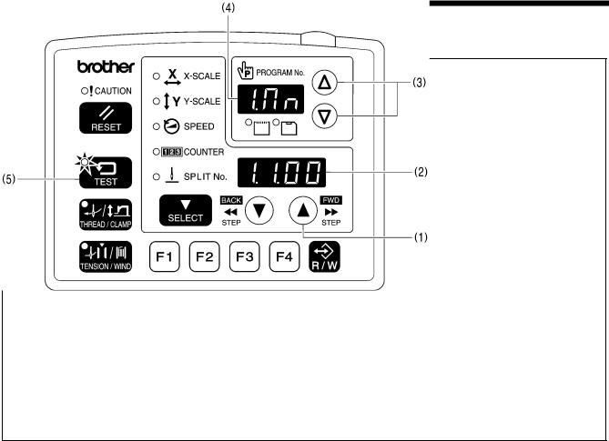
2. FUNCTION SETTINGS
2-10. Software version checking method
5059Q
TEST indicator illuminates, Menu indicator switches off
1.While pressing the  key (1), turn on the power. The software version will be displayed in the menu display (2).
*Keep pressing the  key (1) until the model name is displayed and the buzzer beeps once.
2.The display in the PROGRAM No. display (4) switches as follows each time the  or
or  key (3) is pressed.
PROGRAM No. display (4) |
Software |
[1.Mn] |
Main CPU |
[2.Mt] |
Motor CPU |
[3.PL] |
Panel CPU |
[4.iP] |
Main CPU (IPL) |
[5.PG] |
Programmer |
3.When the TEST key (5) is pressed, the display will return to the normal display and the sewing machine will change to home position standby.
22 |
BAS-311G, BAS-326G |

3. READING / WRITING DATA
3. READING / WRITING DATA
3-1. Handling data
Program numbers (100 − 999) are read from CF cards.
Program numbers (0 − 99) are older BAS-300 series, BAS-300A series and BAS-300E/F series data and can be read from floppy disks.
However, when memory switch No. 755 is set to ON, data for older series models (program numbers 0 − 99) can be transferred from a floppy disk to a CF card using a computer and then be read from the CF card.
* In such cases, the effective reading mode will be [r 1].
Option
0 − 99
or
r9 mode
100 − 999
or
r1 mode
|
|
|
|
|
|
|
|
|
0 − 99 |
|
|
100 − 999 |
|
|
|
|
|
|
|
|
|
|
Old model series data range |
|
BAS-311G, BAS-326G data range |
|
|
|
|
(BAS***.SEW) |
|
ISM***.SEW |
|
|
|
|
|
|
|
|
|
Sewing machine internal memory
|
|
|
|
|
|
|
|
When memory switch |
|
|
or |
|
|
|
|
||
r1 mode |
|
|
|
||
|
No. 755 = ON |
|
|
||
|
|
|
|
|
r1 mode |
|
|
|
|
|
|
|
|
|
|
|
|
|
|
|
|
|
|
|
|
|
|
|
|
Old model series data copied from floppy disk to CF card
(0 − 99)
100 − 999
BAS-311G, BAS-326G |
23 |
Loading...