


 Loading...
BAS-311H
SERVICE MANUAL
Please read this manual before making any adjustments.
DIRECT DRIVE
PROGRAMMABLE ELECTRONIC PATTERN SEWER
This service manual is intended for BAS-311H; be sure to read the BAS-311H instruction manual before this manual.
Carefully read the “SAFETY INSTRUCTIONS” below and the whole of this manual to understand this product before you start maintenance.
As a result of research and improvements regarding this product, some details of this manual may not be the same as those for the product you purchased.
If you have any questions regarding this product, please contact a Brother dealer.
BAS-311H

SAFETY INSTRUCTIONS
[1] Safety indications and their meanings
This service manual and the indications and symbols that are used on the machine itself are provided in order to ensure safe operation of this machine and to prevent accidents and injury to yourself or other people.
The meanings of these indications and symbols are given below.
Indications
DANGER |
The instructions which follow this term indicate situations where failure to follow the |
instructions will result in death or serious injury. |
|
WARNING |
The instructions which follow this term indicate situations where failure to follow the |
instructions could result in death or serious injury. |
|
|
|
CAUTION |
This instructions which follow this term indicate situations where failure to follow the |
instructions may result in minor or moderate injury. |
|
|
|
Symbols |
|
…………………This symbol ( ) indicates something that you should be careful of. The picture inside the triangle indicates the nature of the caution that must be taken.
…………………The symbol ( ) indicates something that you must not do.
…………………The symbol (●) indicates something that you must do. The picture inside the circle indicates the nature of the thing that must be done.
(For example, the symbol at left means “you must make the ground connection”.)
BAS-311H |
i |

[2]Notes on safety
 DANGER
Wait least 5 minutes after turning off the power switch and disconnecting the power cord from the wall outlet before opening the control box cover. Touching areas where high voltages are present can result in severe injury.
 WARNING
Do not allow any liquids to get onto this sewing machine, otherwise fire, electric shocks or operating problems may occur.
If any liquid gets inside the sewing machine (machine head or control box), immediately turn off the power and disconnect the power plug from the electrical outlet, and then contact the place of purchase or a qualified technician.
 CAUTION
Environmental requirements
Use the sewing machine in an area which is free from sources of strong electrical noise such as electrical line noise or static electric noise.
Sources of strong electrical noise may cause problems with correct operation.
Any fluctuations in the power supply voltage should be within ±10% of the rated voltage for the machine. Voltage fluctuations which are greater than this may cause problems with correct operation.
The power supply capacity should be greater than the requirements for the sewing machine’s power consumption.
Insufficient power supply capacity may cause problems with correct operation.
The pneumatic delivery capability should be greater than the requirements for the sewing machine’s total air consumption.
Insufficient pneumatic delivery capability may cause problems with correct operation.
The ambient temperature should be within the range of 5 to 35 during use.
Temperatures which are lower or higher than this may cause problems with correct operation.
The relative humidity should be within the range of 45% to 85% during use, and no dew formation should occur in any devices.
Excessively dry or humid environments and dew formation may cause problems with correct operation.
In the event of an electrical storm, turn off the power and disconnect the power cord from the wall outlet. Lightning may cause problems with correct operation.
Installation
Machine installation should only be carried out by a qualified technician.
Contact your Brother dealer or a qualified electrician for any electrical work that may need to be done.
The sewing machine weights approximately 88 kg.
The installation should be carried out by two or more people.
Do not connect the power cord until installation is complete. If the foot switch is depressed by mistake, the sewing machine might start operating and injury could result.
Hold the machine head with both hands when tilting it back or returning it to its original position.
Furthermore, do not apply excessive force when tilting back the machine head. The sewing machine may become unbalanced and fall down, and serious injury or damage to the sewing machine may result.
Be sure to connect the ground. If the ground connection is not secure, you run a high risk of receiving a serious electric shock, and problems with correct operation may also occur.
All cords should be secured at least 25 mm away from any moving parts. Furthermore, do not excessively bend the cords or secure them too firmly with staples, otherwise there is the danger that fire or electric shocks could occur.
Install the safety covers to the machine head and motor.
If using a work table which has casters, the casters should be secured in such a way so that they cannot move.
Be sure to wear protective goggles and gloves when handling the lubricating oil and grease, so that they do not get into your eyes or onto your skin. If the oil and grease get into your eyes or onto your skin, inflammation can result.
Furthermore, do not drink or eat the lubricating oil or grease. They may cause diarrhea or vomiting.
Keep the oil out of the reach of children.
ii |
BAS-311H |

|
CAUTION |
|
|
|
||
|
Sewing |
|
|
|
|
|
This sewing machine should only be used by |
If using a work table which has casters, the casters |
|||||
operators who have received the necessary training |
should be secured in such a way so that they cannot |
|||||
in safe use beforehand. |
move. |
|
|
|
||
The sewing machine should not be used for any |
Attach all safety devices before using the sewing |
|||||
applications other than sewing. |
machine. If the machine is used without these |
|||||
Be sure to wear protective goggles when using the |
devices attached, injury may result. |
|
||||
|
|
|
|
|||
machine. |
Do not touch any of the moving parts or press any |
|||||
If goggles are not worn, there is the danger that if a |
objects against the machine while sewing, as this |
|||||
needle breaks, parts of the broken needle may enter |
may result in personal injury or damage to the |
|||||
your eyes and injury may result. |
machine. |
|
|
|
||
Turn off the power switch at the following times. If the |
If an error occurs in machine operation, or if abnormal |
|||||
noises or smells are noticed, immediately turn off the |
||||||
foot switch is depressed by mistake, the sewing |
||||||
power switch. Then contact your nearest Brother |
||||||
machine might start operating and injury could result. |
dealer or a qualified technician. |
|
||||
When threading the needle |
If the machine develops a problem, contact your |
|||||
When replacing the bobbin and needle |
nearest Brother dealer or a qualified technician. |
|||||
|
When not using the machine and when leaving |
|
|
|
|
|
|
the machine unattended |
|
|
|
|
|
|
Cleaning |
|
|
|
|
|
Turn off the power switch before carrying out |
Be sure to wear protective goggles and gloves when |
|||||
cleaning. If the foot switch is depressed by mistake, |
handling the lubricating oil and grease, so that they |
|||||
the sewing machine might start operating and injury |
do not get into your eyes or onto your skin. If the oil |
|||||
could result. |
and grease get into your eyes or onto your skin, |
|||||
|
|
inflammation can result. |
|
|
||
|
|
Furthermore, do not drink or eat the lubricating oil or |
||||
|
|
grease. They may cause diarrhea or vomiting. |
||||
|
|
Keep the oil out of the reach of children. |
|
|||
|
|
|
|
|
||
|
Maintenance and inspection |
|
|
|
||
Maintenance and inspection of the sewing machine |
Hold the machine head with both hands when tilting it |
|||||
should only be carried out by a qualified technician. |
back or returning it to its original position. |
|
||||
Ask your Brother dealer or a qualified electrician to |
Furthermore, do |
not apply excessive force when |
||||
tilting back the machine head. The sewing machine |
||||||
carry out any maintenance and inspection of the |
||||||
may become unbalanced and fall down, and serious |
||||||
electrical system. |
||||||
injury or damage to the sewing machine may result. |
||||||
|
|
|||||
Turn off the power switch and disconnect the power |
If the power switch needs to be left on when carrying |
|||||
cord before carrying out the following operations. If |
out some adjustment, be extremely careful to observe |
|||||
the foot switch is depressed by mistake, the sewing |
all safety precautions. |
|
|
|||
machine might start operating and injury could result. |
When replacing |
parts |
and installing |
optional |
||
Inspection, adjustment and maintenance |
||||||
accessories, be sure to |
use only genuine |
Brother |
||||
|
Replacing consumable parts such as the rotary |
|||||
parts. |
|
|
|
|||
|
hook |
|
|
|
||
|
Brother will not be held responsible for any accidents |
|||||
|
|
|||||
Disconnect the air hoses from the air supply and wait |
or problems resulting from the use of non-genuine |
|||||
for the needle on the pressure gauge to drop to “0” |
parts. |
|
|
|
||
before carrying out inspection, adjustment and repair |
If any safety devices have been removed, be |
|||||
of any parts which use the pneumatic equipment. |
absolutely sure to re-install them to their original |
|||||
|
|
positions and check that they operate correctly before |
||||
|
|
using the machine. |
|
|
||
|
|
To prevent accidents and problems, do not modify |
||||
|
|
the machine yourself. |
|
|
||
|
|
Brother will not be held responsible for any accidents |
||||
|
|
or problems resulting from modifications made to the |
||||
|
|
machine. |
|
|
|
|
|
BAS-311H |
|
|
|
iii |
|

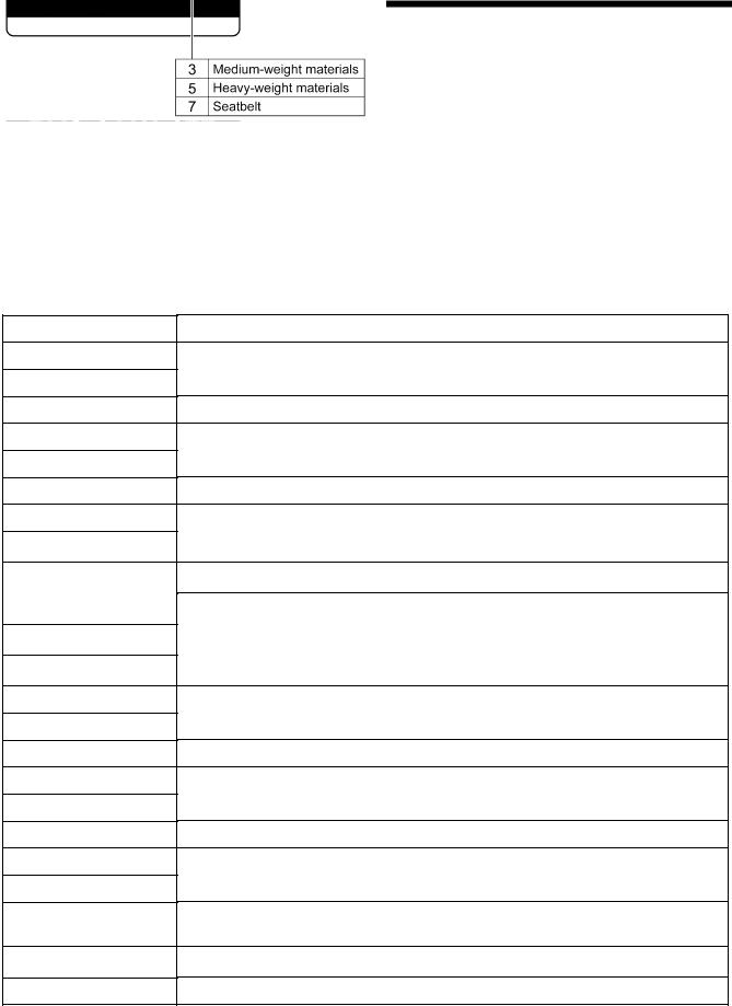
[3]Warning labels
The following warning labels appear on the sewing machine.
Please follow the instructions on the labels at all times when using the machine. If the labels have been removed or are difficult to read, please contact your nearest Brother dealer.
1
2
*Safety devices
3
4
5
6
7
Devices such as eye guard, finger guard, thread take-up cover, side cover, rear cover, tension release solenoid cover, inner cover, outer cover, fixed cover and gas spring support cover
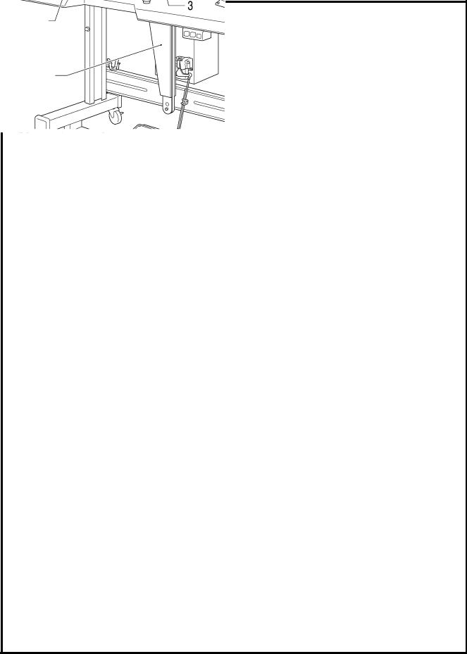
Be careful not to get your hand caught when tilting back the machine head and returning it to its original position.
Be sure to connect the ground. If the ground connection is not secure, you run a high risk of receiving a serious electric shock, and problems with correct operation may also occur.
Direction of operation
Be careful to avoid injury from moving parts.
Do not hold, otherwise problems with operation or injury may occur.
iv |
BAS-311H |
Rear cover
Eye guard
Finger guard
Gas spring support cover
Tension release solenoid cover
Inner cover L
Outer cover
Fixed cover
Side cover
Thread take-up cover
Inner cover R
Outer cover
Fixed cover
3228B |
3029B |
BAS-311H |
v |

CONTENTS
1.SPECIFICATIONS·································· 1
2.NOTES ON HANDLING························ 2
3.FUNCTION SETTINGS ························· 3
3-1. List of special functions when power is turned on ····················································· 3
3-2. List of advanced functions··························· 5
3-3. Setting memory switches (Advanced)········· 6
3-4. List of memory switches ······························ 7
3-5. Setting the work clamp mode···················· 23
3-6. Error history checking method··················· 25
3-7. Input checking method ······························ 26
3-8. Output checking method ··························· 29
3-9. Confirming software version······················ 31
3-10. Protection settings··································· 32
4.X AND Y PARALLEL MOVEMENT OF SEWING PATTERNS ·························· 35
5.USING SD CARD································· 37
5-1. Notes on handling SD cards (commercially available) ··················································· 37
5-2. Structure of an SD card folder··················· 37 5-3. Preparation for reading and writing data ··· 38
5-4. [ |
r 1] Reading additional sewing data······ 39 |
|
5-5. [ |
w 2] Writing additional sewing data to |
|
|
an SD card················································· 40 |
|
5-6. |
[ |
r 3] Reading memory switch data ········· 41 |
5-7. |
[ |
w 4] Writing memory switch data to the |
|
SD card······················································ 42 |
|
5-8. |
[ |
r 5] Reading program data···················· 43 |
5-9. |
[ |
w 6] Writing program data to an SD |
card ··························································· 44
5-10. |
[ |
r 7] Reading sewing machine data ····· 45 |
5-11. |
[ |
w 8] Writing sewing machine data to |
|
an SD card ·············································· 46 |
|
5-12. |
[ |
w 9] Writing error log data and memory |
|
switch log data to an SD card ················· 47 |
|
5-13. |
Updating the control program version····· 48 |
|
6. MECHANICAL DESCRIPTIONS········49
6-1. Needle bar and thread take-up
mechanisms ·············································· 49
6-2. Lower shaft and shuttle race
mechanisms ·············································· 49
6-3. Work clamp lifter mechanism (Motor-driven work clamp specifications) ························ 50
6-4. Work clamp lifter mechanism (Pneumatic work clamp specifications) ························ 51
6-5. Intermittent presser foot lifter
mechanism ················································ 51
6-6. Intermittent presser foot stroke
mechanism ················································ 52 6-7. Feed mechanism······································· 53 6-8. Thread trimmer mechanism ······················ 54 6-9. Tension release mechanism······················ 55 6-10. Thread wiper mechanism························ 55
7. ASSEMBLY ···········································56
7-1. Upper shaft mechanism ···························· 56
7-2. Needle bar mechanism ····························· 58
7-3. Intermittent presser foot lifter
mechanism ················································ 60
7-4. Work clamp lifter mechanism (Motor-driven work clamp specifications) ························ 62
7-5. Work clamp lifter mechanism (pneumatic work clamp specifications) ························ 65
7-6. Feed mechanism······································· 67
7-7. Work clamp arm mechanism····················· 72
7-8. Feed covers··············································· 73
7-9. Lower shaft mechanism ···························· 74
7-10. Shuttle hook mechanism························· 76
7-11. Thread trimmer mechanism ···················· 77
7-12. Tension release mechanism ··················· 81
7-13. Thread wiper mechanism························ 82
7-14. Auxiliary plate·········································· 83
7-15. Covers····················································· 84
BAS-311H

8. ADJUSTMENT······································85
8-1. Checking the machine head switch ···········85
8-2. Standard thread tension·····························86 8-2-1. Upper and lower thread tension·········86 8-3. Thread take-up spring································87 8-4. Arm thread guide R····································87 8-5. Adjusting the needle bar height ·················88
8-6. Adjusting the timing and the driver needle guard··························································88
8-7. Adjusting the needle clearance··················89 8-8. Adjusting the shuttle race thread guide ·····89
8-9. Rotary hook lubrication amount ·················89
8-10. Adjusting the thread trimmer cam
position ····················································90
8-11. Adjusting the position of the movable
knife ·························································90
8-12. Replacing the movable and fixed knives·······················································92
8-13. Installing the feed plate····························93
8-14. Adjusting the thread wiper·······················94
8-15. Presser foot installation position··············94
8-16. Adjusting the intermittent work clamp······95
8-17. Adjusting the work clamp lift amount·······98
8-18. Adjusting the air pressure (pneumatic work clamp specifications)·······················98
8-19. Belt tension adjustment ···························99
8-20. Adjusting the tension release amount ···100
8-21. Adjusting the backlash of the lower
shaft gear···············································101 8-22. Adjusting the home position ··················102
8-22-1. Work clamp lift home position ········102
8-22-2. X-Y feed home position··················105 8-23. Adjusting the motor standard position ···108
8-24. Adjusting the needle up stop position····109
8-25. Setting method for standard depression strokes (Foot switch) ·····························110
9.APPLYING GREASE
(FEED MECHANISM) ························ 111
10. ELECTRIC MECHANISM ···············113
10-1. Precautions at the time of adjustment··· 113
10-2. Components inside and outside the control box and in the operation
panel······················································ 114 10-3. Fuse explanation··································· 115 10-4. Description of connectors ····················· 116 10-4-1. Connector positions ······················· 116
10-4-2. Symptoms when there are poor connections···································· 118
10-5. Troubleshooting ···································· 122
10-5-1. Troubleshooting flowchart·············· 122 10-5-2. Problem solution and measures ···· 126
11.LIST OF ERROR CODES ···············141
12.TROUBLESHOOTING ····················148
13.7-SEGMENT DISPLAY LIST ··········152
BAS-311H
1. SPECFICATIONS
1. SPECFICATIONS
3190B
Sewing machine
Stitch formation
Max. sewing speed
Max. sewing area (XxY)
Feed mechanism
Stitch length
No. of stitches
Maximum No. of stitches
No. of sewing data items that can be stored
Work clamp lift method
Work clamp height
Intermittent presser foot lift amount
Intermittent stroke
Hook
Wiper device
Thread trimmer
Data storage method
User programs
Cycle programs
Motor
Weights
Power source
Air pressure
Lock stitch pattern tacking sewing machine (with large shuttle hook)
Single needle lock stitch
2,800 sti./min
150 x 100 mm
Intermittent feed, pulse motor drive
0.05 − 12.7 mm
500,000-stitch internal memory (*1)
20,000 stitches (per program)
Internal memory: 512 (*1), SD card: 900
Motor-driven work clamp specifications: Pulse motor drive method Pneumatic work clamp specifications: Pneumatic method Motor-driven work clamp specifications: Integrated-type work clamp Pneumatic work clamp specifications: Separate-type work clamp Motor-driven work clamp specifications: Max. 25 mm
Pneumatic work clamp specifications: Max. 30 mm 22 mm
2 − 4.5 mm, 4.5 − 10 mm or 0 (Default setting 3 mm)
Double-capacity shuttle hook (standard shuttle hook sold separately)
Standard equipment
Standard equipment
Internal memory (Flash memory), SD card (*2)
900
30
550 W AC servo motor
Machine head approx. 88 kg, operation panel approx. 0.4 kg Control box 9 kg (Differs depending on destination)
Single-phase 110V / 220V / 230V, 3-phase 220V / 380V / 400V
(For single-phase 110V and three-phase 380V / 400V, the trans box is required.) 0.5 MPa 1.8 l/min.
(*1) The number of data items and stitches that can be stored will vary depending on the number of stitches in each program.
(*2) No guarantees of operation can be given for any media.
1 |
BAS-311H |
2. NOTES ON HANDLING
2. NOTES ON HANDLING
About the machine set-up location
Do not set up this sewing machine near other equipment such as televisions, radios or cordless telephones, otherwise such equipment may be affected by electronic interference from the sewing machine.
The sewing machine should be plugged directly into an AC wall outlet. Operation problems may result if extension cords are used.
Carrying the machine
The machine should be carried by the arm by two people as shown in the illustration.
When holding the machine head, do not hold it by the motor, otherwise it may damage the motor.
Do not hold the shaded parts, as they can bend easily.
Tilting back the machine head
1.Pack away any tools which are near the table.
2.Secure the foot (A) so that the table will not move, and then pull the arm with both hands to tilt back the machine head.
*While supporting the arm with both hands, gently lower it.
Returning the machine head to the upright position
1.Pack away any tools which are near the table.
2.While supporting the arm with both hands, gently return the machine head to its original position.
2516B
3243B
3244B
3245B
BAS-311H |
2 |
3. FUNCTION SETTINGS
3. FUNCTION SETTINGS
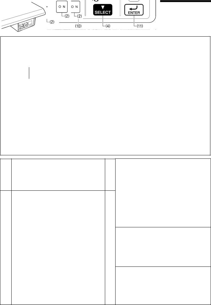
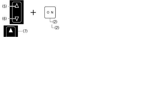
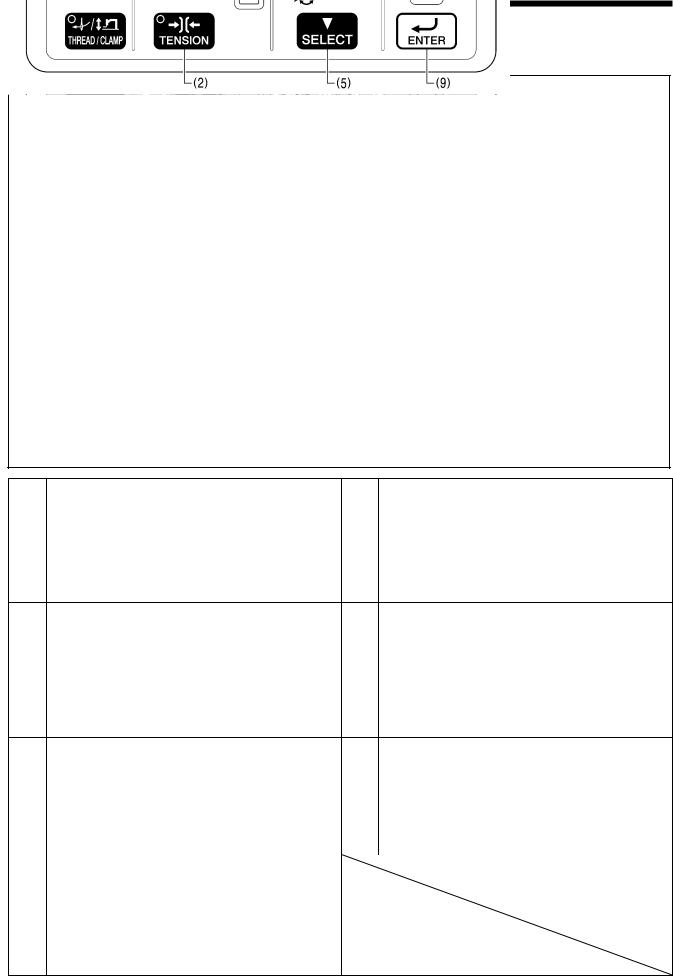
3-1. List of special functions when power is turned on
This list shows the key operations for using special functions.
3055B
(2)
3193B
1 Data initialization function |
2595B 5 |
Refer to the CD Instruction Manual.
2 Memory switch setting mode (Advanced) |
2596B |
6 |
|
|
Software version display function |
2599B |
Refer to “3-9. Confirming software version”.
Error log display function |
2600B |
Refer to “3-3. Setting memory switches (Advanced)”. |
|
Refer to “3-6. Error history checking method”. |
||
|
|
|
|
|
3 Input check function |
2597B |
7 Home position adjusting mode |
2601B |
|
|
|
|||
Refer to “3-7. Input checking method”. |
Refer to “8-22. Adjusting the home position”. |
||
|
|
|
|
4 Output check function |
2598B 8 |
Treadle position adjustment mode |
2602B |
Refer to “3-8. Output checking method”.
Refer to “8- 25. Setting method for standard depression strokes (Foot switch)”.
3 |
BAS-311H |
|
|
|
|
|
|
3. FUNCTION SETTINGS |
|
|
|
|
|
|
|
|
|
|
|
|
|
|
|
|
|
|
9 |
Motor standard position adjustment mode |
2603B |
11 |
Protect setting mode |
2605B |
|
|
|
Refer to “8-23. Adjusting the motor standard position”. |
|
Refer to “3-10. Protection settings”. |
|
||
|
10 |
Needle up stop position adjustment mode |
3194B |
12 |
Version update |
2606B |
|
|
|
Refer to “8-24. Adjusting the needle up stop position”. |
|
Refer to “5-13. Updating the control program version”. |
|
||
|
|
|
|
|
|
|
|
BAS-311H |
4 |
3. FUNCTION SETTINGS
3-2. List of advanced functions
This list shows the key operations for using advanced functions.
3195B
1 Memory switch setting mode (Standard) |
2608B |
|
Refer to the CD Instruction Manual.
2 |
Lower thread counter setting mode |
2609B |
|
|
Refer to the CD Instruction Manual.
3 Production counter setting mode |
2610B |
|
5
6
7
Cycle program setting mode |
2612B |
Refer to the CD Instruction Manual.
Parallel movement mode |
2614B |
Refer to “4. X and Y parallel movement of sewing patterns”.
SD data read/write mode |
2615B |
|
|
Refer to the CD Instruction Manual. |
|
Refer to “5-3. Preparation for reading and writing data”. |
4 |
Program mode |
2611B |
|
|
|
|
|
|
Refer to the CD Instruction Manual.
5 |
BAS-311H |

3. FUNCTION SETTINGS
3-3. Setting memory switches (Advanced)
1 |
Change the mode to memory switch setting mode. |
While pressing the TEST key and the SELECT key, |
|
All indicators switch off |
turn on the power switch. |
|
|
|
|
|
The memory switch number will be displayed in the |
|
|
PROGRAM No. display and the setting value for that |
|
|
number will be displayed in the menu display. |
|
|
3196B 2616B |
|
|
|
2 |
Select the memory switch that you would like |
Press the or key to select the memory switch |
|
to change the setting for. |
number. |
|
|
3210B |
|
If you would like to display only the numbers of |
While pressing the SELECT key, press the or key |
|
memory switches that have been changed from |
(1). |
|
default settings |
The numbers of memory switches that have been |
|
|
changed from default settings will appear in order. |
|
|
2423B |
|
|
|
3 |
Change the memory switch setting. |
Press the ▲ or ▼ key to change the setting value. |
|
|
The flashing display means that the setting has not yet |
|
|
been applied. |
|
|
You can make the initial setting appear in the display |
|
|
by pressing the RESET key. |
|
|
3197B |
|
|
|
4 |
Apply the changed setting. |
Press the ENTER key. |
|
|
The menu display will change from flashing to |
|
|
illuminated, and this means that the parameter setting |
|
|
has been applied. |
|
|
If you press the or key (1) or the TEST key |
|
|
without pressing the ENTER key, you can cancel the |
|
2414B |
parameter changes. |
|
|
|
5 |
Repeat steps 2 to 4 above to set each memory switch. |
|
6 |
Exit setting mode |
Press the TEST key. |
|
|
The changes will be memorized and the sewing |
|
|
machine will switch to home position detection |
|
|
standby. |
|
TEST indicator switches off |
2404B |
BAS-311H |
6 |

3. FUNCTION SETTINGS
3-4. List of memory switches
No. |
Setting |
Settings |
Setting details |
Initial |
Specification |
|
range |
value |
limits |
||||
|
|
|
||||
|
|
Work clamp lift timing after sewing is completed |
|
|
||
|
|
0 |
Work clamp is not raised automatically. |
|
|
|
|
|
|
Work clamp is raised at the final stitch position. |
|
|
|
001 |
0-2 |
1 |
* Disabled when memory switch No. 71 is set to “2”, or when |
2 |
None |
|
|
memory switch No. 72 is set to “2”. |
|||||
|
|
|
|
|
||
|
|
|
Work clamp is raised after moving to the home position. |
|
|
|
|
|
2 |
* Disabled when memory switch No. 71 is set to "2", or when |
|
|
|
|
|
|
memory switch No. 72 is set to "2". |
|
|
|
|
|
Work clamp lowering sequence for separate work clamp |
|
|
||
|
|
(Pneumatic work clamp specifications only) |
|
|
||
002 |
0-2 |
0 |
Left and right work clamps are lowered at the same time. |
0 |
Pneumatic |
|
|
|
1 |
Work clamp is lowered in the order left → right. |
|
|
|
|
|
2 |
Work clamp is lowered in the order right → left. |
|
|
|
|
|
Work clamp lowering operation (Motor-driven work clamp specifications only) |
|
|
||
|
|
|
|
|
|
|
|
|
|
Analog lowering: Work clamp is lowered in direct proportion to the |
|
|
|
|
|
|
pedal depression amount, and sewing starts when the pedal is fully |
|
|
|
|
|
0 |
depressed. |
|
|
|
|
|
* This operation is only possible for foot switch specifications; for |
|
|
||
|
|
|
|
|
||
|
|
|
two-pedal foot switch specifications, operation is the same as for a |
|
|
|
003 |
0-2 |
|
2-step work clamp. |
2 |
Solenoid |
|
|
1-step work clamp: Work clamp is lowered when pedal is depressed |
|||||
|
|
|
|
|
||
|
|
1 |
to the 1st step, and sewing starts when pedal is depressed to the |
|
|
|
|
|
|
2nd step. |
|
|
|
|
|
|
2-step work clamp: Work clamp is lowered to intermediate height |
|
|
|
|
|
2 |
when pedal is depressed to the 1st step, and work clamp is fully |
|
|
|
|
|
lowered and sewing starts when the pedal is depressed to the 2nd |
|
|
||
|
|
|
|
|
||
|
|
|
step. |
|
|
|
|
|
Slow start method |
|
|
||
|
|
OFF |
The sewing speed for the first 5 stitches will be in accordance with |
OFF |
|
|
100 |
ON/OFF |
the setting for memory switch Nos. 151 to 155. |
|
|||
|
|
None |
||||
|
The sewing speed for the first 5 stitches can be selected from the |
|
||||
|
|
|
|
|||
|
|
ON |
nine slow start patterns “Lo1” to “Lo9”. (Refer to the CD Instruction |
Lo4 |
|
|
|
|
|
Manual.) |
|
|
|
|
|
Single-stitch test feed |
|
|
||
|
|
OFF |
Test feed starts when the foot switch (start switch) is depressed, and |
|
|
|
|
|
it continues automatically until the final stitch. |
|
|
||
|
|
|
|
|
||
200 |
ON/OFF |
|
Test feed starts when the foot switch (start switch) is depressed, and |
OFF |
None |
|
|
it moves forward by one stitch each time the switch is depressed. |
|||||
|
|
|
|
|
||
|
|
ON |
In addition, when the TEST indicator is flashing, test feed will move |
|
|
|
|
|
|
forward one stitch at a time when the machine pulley is turned by |
|
|
|
|
|
|
hand. |
|
|
|
|
|
Production counter display |
|
|
||
300 |
ON/OFF |
OFF |
Lower thread counter display |
OFF |
None |
|
|
|
ON |
Production counter display |
|
|
|
|
|
Sewing condition detail settings |
|
|
||
400 |
ON/OFF |
OFF |
Parameters which are common to all programs are used. |
OFF |
None |
|
|
|
ON |
Parameters can be set separately for each program. |
|||
|
|
|
|
|||
|
|
|
|
|
|
|
|
|
Unit display for pattern zoom ratio |
|
|
||
402 |
ON/OFF |
OFF |
Displayed as % |
OFF |
None |
|
|
|
ON |
Displayed as mm |
|
|
|
|
|
Split mode selection |
|
|
||
403 |
0-1 |
0 |
Continuous split mode |
0 |
None |
|
|
|
1 |
Single split mode |
|
|
|
405 |
|
Cycle program No. (C01 to C30) display |
|
|
||
ON/OFF |
OFF |
Disabled (Skipped) |
ON |
None |
||
*1 |
||||||
|
ON |
Enabled |
|
|
||
|
|
|
|
|||
7 |
BAS-311H |

3. FUNCTION SETTINGS
No. |
Setting |
Settings |
Settings details |
Initial |
Specification |
|
range |
value |
limits |
||||
|
|
|
||||
|
|
F key specifications |
|
|
||
|
|
0 |
F keys become direct selection keys for sewing program numbers |
|
|
|
|
|
(101 to 104). |
|
|
||
|
|
|
|
|
||
|
|
|
F keys become direct selection keys for cycle program numbers |
|
|
|
406 |
|
1 |
(C01 to C04). |
|
|
|
0-2 |
|
* Selection is possible when memory switch No. 400 is set to “ON”. |
0 |
None |
||
*2 |
|
|
||||
|
F keys become shortcut keys for program numbers which have been |
|||||
|
|
|
|
|||
|
|
|
assigned to the keys. |
|
|
|
|
|
2 |
F1 … Setting number for memory switch No. 407 |
|
|
|
|
|
F2 … Setting number for memory switch No. 408 |
|
|
||
|
|
|
|
|
||
|
|
|
F3 … Setting number for memory switch No. 409 |
|
|
|
|
|
|
F4 … Setting number for memory switch No. 410 |
|
|
|
407 |
|
Assignment number to F1 key |
101 |
None |
||
|
|
100-999, C01-C30 |
||||
|
|
|
|
|
||
408 |
|
Assignment number to F2 key |
102 |
None |
||
|
|
100-999, C01-C30 |
||||
|
|
|
|
|
||
409 |
|
Assignment number to F3 key |
103 |
None |
||
|
|
100-999, C01-C30 |
||||
|
|
|
|
|
||
410 |
|
Assignment number to F4 key |
104 |
None |
||
|
|
100-999, C01-C30 |
||||
|
|
|
|
|
||
*1: If there are no valid sewing programs when memory switch No. 405 is set to "OFF", only the standard program numbers are displayed. If it is set to "ON" when no programs have been registered, nothing is displayed (the display is skipped).
*2: If an F key which does not have a program registered to it is pressed, the key will be invalid. (The buzzer will sound twice.)
BAS-311H |
8 |

3. FUNCTION SETTINGS
Work clamp settings
No. |
Setting |
Settings |
Settings details |
Initial |
Specification |
|
range |
value |
limits |
||||
|
|
|
||||
|
|
Work clamp operation before home position detection |
|
|
||
|
|
OFF |
Work clamp cannot be raised or lowered before home position is |
|
|
|
051 |
ON/OFF |
detected. *1 |
ON |
None |
||
|
||||||
|
|
ON |
Work clamp can be raised and lowered before home position is |
|
|
|
|
|
detected. |
|
|
||
|
|
|
|
|
||
|
|
Work clamp operation during split programs |
|
|
||
052 |
ON/OFF |
OFF |
Work clamp lifts automatically when sewing pauses due to a split |
OFF |
None |
|
program. |
||||||
|
||||||
|
|
ON |
Work clamp does not lift automatically when sewing pauses due to a |
|
|
|
|
|
split program. |
|
|
||
|
|
|
|
|
||
053 |
0-999 |
Time from intermittent presser foot lifting until feed mechanism starts moving |
100 |
None |
||
|
Units (ms), Increments of 1 |
|||||
|
|
|
|
|
||
|
|
Intermittent presser foot drop timing |
|
|
||
|
|
0 |
Presser foot drops when the work clamp switch is depressed, but it |
|
|
|
|
|
does not drop at the retract position. |
|
|
||
054 |
0-2 |
|
0 |
None |
||
1 |
Presser foot drops when the work clamp switch is depressed. |
|||||
|
|
|
|
|||
|
|
2 |
Presser foot drops at the sewing start, regardless of the work clamp |
|
|
|
|
|
switch operation. |
|
|
||
|
|
|
|
|
||
|
|
Work clamp signal valve special output for pneumatic-type work clamp |
|
|
||
|
|
0 |
Disabled |
|
|
|
|
|
|
Valve output is reversed for pneumatic-type work clamp |
|
|
|
|
|
1 |
specifications. |
|
|
|
055 |
0-2 |
(Connect the air tubes in reverse so that the work clamp can lift |
0 |
Pneumatic |
||
|
||||||
|
when the power is turned off.) |
|||||
|
|
|
|
|
||
|
|
|
Reverse valve output for pneumatic specifications is output |
|
|
|
|
|
2 |
simultaneously for 2-position valve specifications. |
|
|
|
|
|
(Right work clamp reverse = Option output No. 4: Left work clamp |
|
|
||
|
|
|
|
|
||
|
|
|
reverse = Option output No. 5) |
|
|
|
|
|
Thread winding operation before home position is detected |
|
|
||
056 |
ON/OFF |
OFF |
Thread winding cannot be carried out before home position is |
OFF |
None |
|
detected. |
||||||
|
|
|
|
|
||
|
|
ON |
Thread winding can be carried out before home position is detected. |
|
|
|
|
|
Work clamp operation when feed moves to sewing start position after home |
|
|
||
|
|
position is detected |
|
|
||
057 |
ON/OFF |
OFF |
Work clamp stays dropped after home position is detected. |
ON |
None |
|
Work clamp lifts when work clamp switch is depressed (when |
||||||
|
|
|
|
|||
|
|
|
depressed backward for foot switch). |
|
|
|
|
|
ON |
Work clamp lifts automatically after home position is detected. |
|
|
|
|
|
Operation settings for heavy-weight materials |
|
|
||
059 |
0-1 |
0 |
Standard |
0 |
Pneumatic |
|
1 |
When using a heavy work clamp and feed plate |
|||||
|
|
|
|
|||
|
|
(Maximum sewing speed is limited to 2,200 sti./min.) |
|
|
||
|
|
|
|
|
||
060 |
0-3000 |
Time after the work clamp drops until the shaft starts rotating. |
0 |
None |
||
|
|
|||||
|
Units (ms), Increments of 10 |
|||||
|
|
|
|
|
||
|
|
|
|
|
|
|
*1: If memory switch No. 051 is set to "OFF", thread winding is not possible before home position detection is carried out. Thread winding is not possible during intermittent lifting and before work clamp home position detection is carried out (such as when the work clamp switch has not been depressed at all after the power was turned on), even when memory switch No. 056 is set to "ON".
9 |
BAS-311H |

3. FUNCTION SETTINGS
Pedal type and work clamp operation settings
No. |
Setting |
Settings |
Settings details |
Initial |
Specification |
|
range |
value |
limits |
||||
|
|
|
||||
|
|
Pedal specifications (Not reset during initialization) |
|
|
||
|
|
|
Foot switch |
|
|
|
|
|
1 |
(Memory switch No. 71 can be set, and memory switch Nos. 72 and |
1 |
|
|
|
|
|
73 are not displayed.) |
|
||
|
|
|
(Solenoid) |
|
||
|
|
|
Two-pedal foot switch |
None |
||
070 |
1-3 |
2 |
2 |
|||
(Memory switch No. 72 can be set, and memory switch Nos. 71 and |
||||||
|
|
(Pneumatic) |
|
|||
|
|
|
73 are not displayed.) |
|
|
|
|
|
|
Three-pedal foot switch |
|
|
|
|
|
3 |
(Memory switch No. 73 can be set, and memory switch Nos. 71 and |
|
|
|
|
|
|
72 are not displayed.) |
|
|
|
|
|
Work clamp operation when foot switch is set |
|
|
||
|
|
(Can be set when memory switch No. 70 is set to "1". Not displayed at other |
|
|
||
|
|
times.) |
|
|
|
|
|
|
(Not reset during initialization) |
|
|
||
|
|
1 |
[Standard] |
|
None |
|
071 |
1-3 |
2 |
[No automatic work clamp lifting] |
1 |
None |
|
Work clamp lifts when pedal is depressed backward. |
||||||
|
|
|||||
|
|
|
[2-step work clamp using two presses] |
|
|
|
|
|
|
When work clamp switch is depressed: (1st step) Drop → (2nd step) |
|
|
|
|
|
3 |
Drop (skipped for single step work clamp) → Start |
|
Solenoid |
|
|
|
When depressed backward = Both work clamps lift |
|
|||
|
|
|
|
|
||
|
|
|
* Operates as a 2-step work clamp when memory switch No. 003 is |
|
|
|
|
|
|
set to "0". |
|
|
|
|
|
Work clamp operation when two-pedal foot switch is set |
|
|
||
|
|
(Can be set when memory switch No. 70 is set to "2". Not displayed at other |
|
|
||
|
|
times.) |
|
|
|
|
|
|
(Not reset during initialization) |
|
|
||
|
|
|
[Standard] |
|
|
|
|
|
|
Work clamp lifts automatically and drops when the work clamp |
|
|
|
|
|
1 |
switch is depressed. |
|
None |
|
|
|
|
The left and right order can be changed using memory switch No. |
|
|
|
|
|
|
002. |
|
|
|
|
|
2 |
[No automatic work clamp lifting] |
|
None |
|
|
|
Work clamp lifts while work clamp switch is being depressed. |
|
|||
|
|
|
|
|
||
|
|
|
[Left/right work clamp → intermittent presser foot 2-step work clamp] |
|
|
|
|
|
|
When work clamp switch is depressed to the 1st step, both the left |
|
|
|
|
|
3 |
and right work clamps are lowered, and when it is depressed to the |
|
Pneumatic |
|
|
|
|
2nd step, the intermittent presser foot is lowered. |
|
|
|
|
|
|
Lifting is in the same order. |
|
|
|
|
|
|
[Left and right alternating 2-step work clamp] |
|
|
|
|
|
4 |
2-step operation, with left and right order switching for each item |
|
Pneumatic |
|
072 |
1-7 |
sewn. |
1 |
|||
|
|
|||||
|
|
|
Starts from right. |
|
|
|
|
|
|
[Forward/reverse pedal] |
|
|
|
|
|
|
When the start switch is depressed, the work clamp drops and the |
|
|
|
|
|
|
sewing machine starts in that order with forward control, and when |
|
|
|
|
|
5 |
the work clamp switch is depressed, the sewing machine reverses |
|
Pneumatic |
|
|
|
|
and the work clamp lifts. |
|
|
|
|
|
|
* The left and right order can be changed using memory switch No. |
|
|
|
|
|
|
002. |
|
|
|
|
|
|
[2-step work clamp using two presses] |
|
|
|
|
|
|
When the work clamp switch is depressed, the left work clamp drops |
|
|
|
|
|
6 |
→ Right work clamp drops → Both work clamps lift in that order |
|
Pneumatic |
|
|
|
|
* The left and right order can be changed using memory switch No. |
|
|
|
|
|
|
002. |
|
|
|
|
|
|
[Work clamp drops and sewing starts only when work clamp switch is |
|
|
|
|
|
|
depressed] |
|
|
|
|
|
7 |
Work clamp drops and sewing starts only by depressing the work |
|
None |
|
|
|
|
clamp switch. |
|
|
|
|
|
|
* Starting sewing is also possible by using the start switch. |
|
|
|
BAS-311H |
10 |

3. FUNCTION SETTINGS
No. |
Setting |
Settings |
Settings details |
Initial |
Specification |
|
range |
value |
limits |
||||
|
|
|
||||
|
|
Work clamp operation when three-pedal foot switch is set |
|
|
||
|
|
(Can be set when memory switch No. 70 is set to "3". Not displayed at other |
|
|
||
|
|
times.) |
|
|
|
|
|
|
(Not reset during initialization) |
|
|
||
|
|
|
[Standard] |
|
|
|
|
|
|
Pneumatic method: The left pedal raises and lowers the left work |
|
|
|
|
|
|
clamp, and the right pedal (center) raises and lowers the right work |
|
|
|
|
|
|
clamp. |
|
|
|
|
|
1 |
The start switch (right) starts the sewing machine. |
|
None |
|
|
|
|
Motor-driven method (Solenoid) : 1st step when left pedal is |
|
|
|
|
|
|
depressed: 2nd step when right (center) pedal is depressed (invalid |
|
|
|
|
|
|
for single step work clamp) |
|
|
|
073 |
1-3 |
|
The start switch (right) starts the sewing machine. |
1 |
|
|
|
[Independent home detection] |
|
||||
|
|
|
|
|
||
|
|
|
The right pedal (center) is used exclusively for detecting the home |
|
|
|
|
|
2 |
position. |
|
Pneumatic |
|
|
|
The left pedal raises and lowers the left and right work clamps, and |
|
|||
|
|
|
|
|
||
|
|
|
the start pedal (right) starts the sewing machine. |
|
|
|
|
|
|
The start switch (right) starts the sewing machine. |
|
|
|
|
|
|
[Independent home detection] |
|
|
|
|
|
|
The right pedal (center) is used exclusively for detecting the home |
|
|
|
|
|
|
position. |
|
|
|
|
|
3 |
The left work clamp only is raised and lowered when the left pedal is |
|
Pneumatic |
|
|
|
|
depressed. |
|
|
|
|
|
|
The start switch (right) lowers the right work clamp and starts the |
|
|
|
|
|
|
sewing machine. |
|
|
|
11 |
BAS-311H |
3. FUNCTION SETTINGS
Upper shaft motor settings
No. |
Setting |
Settings |
Settings details |
Initial |
Specification |
|
range |
value |
limits |
||||
|
|
|
||||
|
|
Highest needle position stop (When set to "ON", memory switch Nos. 165 and |
|
|
||
|
|
166 can be set.) |
|
|
||
|
|
OFF |
|
|
|
|
|
|
|
When the upper shaft motor stops, the motor operation reverse to |
OFF |
|
|
150 |
ON/OFF |
|
return the needle bar close to its highest position. |
None |
||
|
|
ON |
* When the motor operates in reverse to raise the needle, the thread |
|
|
|
|
|
take-up will stop at a position which is lower than its normal |
|
|
||
|
|
|
stopping position. As a result, the thread take-up will rise slightly at |
|
|
|
|
|
|
the sewing start, and this may result in the thread pulling out under |
|
|
|
|
|
|
certain conditions. |
|
|
|
151 |
200-2800 |
1st stitch sewing speed at the sewing start |
400 |
None |
||
*1 |
|
Units ( sti./min ), Increments of 100 |
||||
|
|
|
|
|||
152 |
200-2800 |
2nd stitch sewing speed at the sewing start |
800 |
None |
||
*1 |
|
Units ( sti./min ), Increments of 100 |
||||
|
|
|
|
|||
153 |
200-2800 |
3rd stitch sewing speed at the sewing start |
1200 |
None |
||
*1 |
|
Units ( sti./min ), Increments of 100 |
||||
|
|
|
|
|||
154 |
200-2800 |
4th stitch sewing speed at the sewing start |
2800 |
None |
||
*1 |
|
Units ( sti./min ), Increments of 100 |
||||
|
|
|
|
|||
155 |
200-2800 |
5th stitch sewing speed at the sewing start |
2800 |
None |
||
*1 |
|
Units ( sti./min ), Increments of 100 |
||||
|
|
|
|
|||
|
|
|
|
|
|
|
156 |
200-2800 |
Sewing speed for 5th stitch before the sewing end |
2800 |
None |
||
|
Units ( sti./min ), Increments of 100 |
|||||
|
|
|
|
|
||
|
|
|
|
|
|
|
157 |
200-2800 |
Sewing speed for 4th stitch before the sewing end |
2800 |
None |
||
|
Units ( sti./min ), Increments of 100 |
|||||
|
|
|
|
|
||
|
|
|
|
|
|
|
158 |
200-2800 |
Sewing speed for 3rd stitch before the sewing end |
2800 |
None |
||
|
Units ( sti./min ), Increments of 100 |
|||||
|
|
|
|
|
||
159 |
200-2000 |
Sewing speed for 2nd stitch before the sewing end |
1200 |
None |
||
|
Units ( sti./min ), Increments of 100 |
|||||
|
|
|
|
|
||
|
|
Piercing force boosting operation |
|
|
||
161 |
ON/OFF |
OFF |
Disabled |
OFF |
None |
|
ON |
Enabled (Piercing force boosting operations are carried out when the |
|||||
|
|
|
|
|||
|
|
sewing machine motor is locked.) |
|
|
||
|
|
|
|
|
||
|
|
Regulation of sewing speed changes due to sewing pitch changes |
|
|
||
|
|
OFF |
Sewing speed varies depending on sewing pitch of the sewing data. |
|
|
|
162 |
ON/OFF |
|
Speed is fixed at the minimum sewing speed for the maximum pitch |
OFF |
None |
|
|
|
ON |
of the sewing data. |
|
|
|
|
|
(Set to “ON” if there may be a problem with sewing speed changes |
|
|
||
|
|
|
|
|
||
|
|
|
as a result of pitch changes.) |
|
|
|
|
|
The maximum value is limited when the sewing speed is set using the menu. |
|
|
||
|
1200- |
It is applied to the panel speed display. |
|
|
||
163 |
The maximum values are limited for all speed setting values which have been |
2800 |
None |
|||
2800 |
||||||
|
programmed. |
|
|
|||
|
|
|
|
|||
|
|
|
Units (sti./min), Increments of 100 |
|
|
|
|
|
Thread trimming disabled |
|
|
||
164 |
ON/OFF |
OFF |
Thread trimming is carried out in accordance with the sewing data. |
OFF |
None |
|
|
|
ON |
Thread trimming is not carried out. |
|
|
|
BAS-311H |
12 |

3. FUNCTION SETTINGS
No. |
Setting |
Settings |
Settings details |
Initial |
Specification |
|
range |
value |
limits |
||||
|
|
|
||||
|
|
Stop position settings at highest needle position stop |
|
|
||
|
|
(Can only be set when memory switch No. 150 is set to "ON", not displayed at |
|
|
||
165 |
-20-20 |
other times.) |
0 |
None |
||
|
|
|
Needle bar height increases for values in the negative direction. |
|
|
|
|
|
|
Units (degree), Increments of 1 |
|
|
|
|
|
Delay time until reverse operation starts during highest needle position stop |
|
|
||
|
|
operation |
|
|
|
|
166 |
10-500 |
(Can only be set when memory switch No. 150 is set to "ON", not displayed at |
150 |
None |
||
other times.) |
||||||
|
|
|
|
|||
|
|
|
Units (ms), Increments of 10 |
|
|
|
|
|
|
|
|
|
|
|
|
Servo lock enabled or disabled setting |
|
|
||
167 |
ON/OFF |
(When set to "ON", memory switch Nos. 168 and 169 can be set.) |
OFF |
None |
||
OFF |
Disable |
|||||
|
|
|
|
|||
|
|
ON |
Enable |
|
|
|
|
|
Servo lock timer setting |
|
|
||
168 |
0-120 |
(Can only be set when memory switch No. 167 is set to "ON", not displayed at |
0 |
None |
||
other times. If it is set to “0”, no timer operation. |
||||||
|
|
|
|
|||
|
|
|
Units (s), Increments of 1 |
|
|
|
|
|
Servo lock release rotation angle |
|
|
||
169 |
30-89 |
(Can only be set when memory switch No. 167 is set to "ON", not displayed at |
45 |
None |
||
other times.) |
||||||
|
|
|
|
|||
|
|
|
Units (degree), Increments of 1 |
|
|
|
|
|
Lowers the allowable speed for the sewing pitch by the amount set. |
|
|
||
170 |
0-2800 |
|
Overall speed reduction (sti./min) Increments of 100 |
0 |
None |
|
|
|
|
However, the minimum allowable speed value is 400 sti./min. |
|
|
|
|
|
Automatic needle lifter operation |
|
|
||
|
|
|
Does not operate automatically, and a needle up stop position error |
|
|
|
|
|
OFF |
is generated. |
|
|
|
|
|
(When memory switch No. 655 is set to "ON", the sensor can also |
|
|
||
171 |
ON/OFF |
|
ON |
None |
||
|
be ignored.) |
|||||
|
|
|
|
|
||
|
|
ON |
If the needle bar is not at the needle up stop position during feeding |
|
|
|
|
|
or work clamp home position detection, it moves automatically to the |
|
|
||
|
|
|
needle up stop position. |
|
|
|
*1: Only enabled when memory switch No. 100 is set to "OFF".
13 |
BAS-311H |

3. FUNCTION SETTINGS
Feed settings
No. |
Setting |
Settings |
|
Settings details |
|
Initial |
Specification |
|
range |
|
|
value |
limits |
||||
|
|
|
|
|
||||
|
|
Mechanism home position return when sewing is finished |
|
|
|
|||
250 |
ON/OFF |
OFF |
When sewing is finished, the feed returns to the start position. |
|
OFF |
None |
||
ON |
When sewing is finished, the feed moves via the machine home |
|||||||
|
|
|
|
|||||
|
|
position to the start position. |
|
|
|
|||
|
|
|
|
|
|
|||
|
|
The speed of the feeding operation |
|
|
|
|||
|
|
1 |
Slow |
100 mm/s |
|
|
|
|
251 |
1-5 |
2 |
|
200 mm/s |
|
3 |
None |
|
3 |
|
300 mm/s |
|
|||||
|
|
|
|
|
|
|||
|
|
4 |
|
400 mm/s |
|
|
|
|
|
|
5 |
Fast |
500 mm/s |
|
|
|
|
|
|
High-speed test feed method |
|
|
|
|||
252 |
|
|
Normally slow, but becomes faster when the foot switch is |
|
|
|
||
ON/OFF |
OFF |
depressed to the 1st step. |
|
OFF |
None |
|||
*1 |
(For a two-pedal foot switch, when the work clamp switch is |
|||||||
|
|
|
|
|||||
|
|
|
depressed.) |
|
|
|
||
|
|
ON |
High-speed feeding starts at the same time test feeding starts. |
|
|
|
||
|
|
Moving method to the start point (Not reset during initialization) |
|
|
|
|||
|
|
|
Depress the foot switch to the 2nd step while the program number is |
|
|
|||
|
|
0 |
flashing. |
|
|
|
||
|
|
|
(For a two-pedal foot switch, depress the start switch.) |
|
|
|
||
|
|
|
When the RESET key is pressed while the program number is |
|
|
|||
|
|
|
flashing: |
|
|
|
||
|
|
|
When work clamp is lowered before moving to sewing start |
|
|
|||
|
|
|
position → Moves to sewing start position |
|
|
|
||
|
|
1 |
When work clamp is lowered after moving to sewing start position |
|
|
|||
|
|
→ Ignored |
|
|
|
|||
|
|
|
|
|
|
|||
|
|
|
When work clamp is raised before moving to sewing start position |
|
|
|||
253 |
0-2 |
|
→ Work clamp is lowered + Moves to sewing start position |
|
0 |
None |
||
|
When work clamp is raised after moving to sewing start position |
→ |
||||||
|
|
|
|
|
||||
|
|
|
Ignored |
|
|
|
||
|
|
|
When the expansion input switch (EXIN3) is pressed while the |
|
|
|
||
|
|
|
program number is flashing: |
|
|
|
||
|
|
|
When work clamp is lowered before moving to sewing start |
|
|
|
||
|
|
2 |
position → Moves to sewing start position |
|
|
|
||
|
|
When work clamp is lowered after moving to sewing start position |
|
|
||||
|
|
*2 |
→ Ignored |
|
|
|
||
|
|
|
When work clamp is raised before moving to sewing start position |
|
|
|||
|
|
|
→ Ignored |
|
|
|
||
|
|
|
When work clamp is raised after moving to sewing start position → |
|
|
|||
|
|
|
Ignored |
|
|
|
||
|
|
Movement path from mechanism home position to start position (Not reset |
|
|
||||
|
|
during initialization) |
|
|
|
|||
|
|
0 |
No route specified |
|
|
|
||
|
|
|
|
|
|
|||
254 |
0-3 |
1 |
Moves in the order X→Y when moving to the home position, and in |
0 |
None |
|||
the order Y→X when moving to the sewing start position. |
|
|||||||
|
|
|
|
|
|
|||
|
|
2 |
Moves in the order Y→X when moving to the home position, and in |
|
|
|||
|
|
the order X→Y when moving to the sewing start position. |
|
|
|
|||
|
|
|
|
|
|
|||
|
|
3 |
Operates while avoiding the center of the clamped area. |
|
|
|
||
|
|
Y-feed full stroke movement operation |
|
|
|
|||
|
|
|
Y-feed full stroke movement operation does not occur when home |
|
|
|||
255 |
ON/OFF |
OFF |
position detection is carried out immediately after the power |
is |
ON |
None |
||
|
turned on. |
|
||||||
|
|
|
|
|
|
|||
|
|
ON |
Y-feed full stroke movement operation occurs when home position |
|
|
|||
|
|
detection is carried out immediately after the power is turned on. |
|
|
|
|||
|
|
|
|
|
|
|||
260 |
-80-80 |
Changes the overall feed timing (-80 Early ←→80: Late) |
|
0 |
None |
|||
|
Units (degree), Increments of 1 |
|
||||||
|
|
|
|
|
|
|||
*1: Only enabled when memory switch No. 200 is set to "OFF". |
|
|
|
|||||
*2: The start switch is disabled. Cannot be set when memory switch No.650 is set to "2". |
|
|
|
|||||
BAS-311H |
14 |

3. FUNCTION SETTINGS
No. |
Setting |
Settings |
Setting details |
Initial |
Specification |
|
range |
value |
limits |
||||
|
|
|
||||
|
|
Changes the feed timing for the 1st stitch at the sewing start |
|
|
||
261 |
-80-80 |
(-80 Early ←→80: Late) |
0 |
None |
||
|
|
|
Units (degree), Increments of 1 |
|
|
|
|
|
Changes the feed timing for the 2nd stitch at the sewing start |
|
|
||
262 |
-80-80 |
(-80 Early←→80: Late) |
0 |
None |
||
|
|
|
Units (degree), Increments of 1 |
|
|
|
|
|
Changes the feed timing for the 3rd stitch at the sewing start |
|
|
||
263 |
-80-80 |
(-80 Early ←→80: Late) |
0 |
None |
||
|
|
|
Units (degree), Increments of 1 |
|
|
|
|
|
Changes the feed timing for the 3rd stitch before the sewing end |
|
|
||
264 |
-80-80 |
(-80 Early←→80: Late) |
0 |
None |
||
|
|
|
Units (degree), Increments of 1 |
|
|
|
|
|
Changes the feed timing for the 2nd stitch before the sewing end |
|
|
||
265 |
-80-80 |
(-80 Early ←→80: Late) |
0 |
None |
||
|
|
|
Units (degree), Increments of 1 |
|
|
|
|
|
Changes the feed timing for the 1st stitch before the sewing end |
|
|
||
266 |
-80-80 |
(-80 Early ←→80: Late) |
0 |
None |
||
|
|
|
Units (degree), Increments of 1 |
|
|
|
|
|
When the overall feed timing has been changed using memory switch No. 260, |
|
|
||
|
|
this specifies the effective number of stitches. |
|
|
||
267 |
0-99 |
0 |
No limit |
0 |
None |
|
|
|
1-99 |
When the specified number of stitches is exceeded, the feed timing |
|
|
|
|
|
returns to the standard timing. |
|
|
||
|
|
|
|
|
||
|
|
Changes the overall feed timing reference |
|
|
||
|
|
0 |
[Feed start reference] Makes the timing uniform at the start of feed. |
|
|
|
|
|
1 |
[Needle up reference] Changes the timing at the start of feed so that |
|
|
|
268 |
0-3 |
the needle zigzagging is even. |
1 |
None |
||
|
||||||
|
|
2 |
[Feed end reference] Makes the timing uniform at the end of feed. |
|
|
|
|
|
|
|
|
|
|
|
|
3 |
[Linked to speed] Feed timing is uniform even if the sewing speed |
|
|
|
|
|
changes. |
|
|
||
|
|
|
|
|
||
|
|
Changes the feed timing reference for the first three stitches at the sewing start |
|
|
||
|
|
0 |
[Feed start reference] Makes the timing uniform at the start of feed. |
|
|
|
269 |
0-2 |
1 |
[Needle up reference] Changes the timing at the start of feed so that |
1 |
None |
|
|
|
the needle zigzagging is even. |
|
|
||
|
|
|
|
|
||
|
|
2 |
[Feed end reference] Makes the timing uniform at the end of feed. |
|
|
|
|
|
Home position detection operation when the program is changed |
|
|
||
|
|
|
Home position detection is not carried out. |
|
|
|
|
|
0 |
Moves to sewing start position when start switch is depressed, and |
|
|
|
|
|
|
then stops. |
|
|
|
|
|
|
Home position detection is not carried out. |
|
|
|
270 |
0-3 |
1 |
Moves via the center of the sewing area to the sewing start position |
0 |
None |
|
|
when start switch is depressed, and then stops. |
|||||
|
|
|
Home position detection is carried out. |
|
|
|
|
|
2 |
Moves to sewing start position after home position detection when |
|
|
|
|
|
|
start switch is depressed, and then stops. |
|
|
|
|
|
|
Home position detection is not carried out. |
|
|
|
|
|
3 |
If the program has changed, moves to the next sewing start position |
|
|
|
|
|
|
and then stops. |
|
|
|
15 |
BAS-311H |

3. FUNCTION SETTINGS
Panel operation settings
No. |
Setting |
Settings |
Setting details |
Initial |
Specification |
|
range |
value |
limits |
||||
|
|
|
||||
|
|
Counting method for production counter and lower thread counter |
|
|
||
|
|
0 |
Counted for each item of sewing data. |
|
|
|
352 |
0-2 |
1 |
Counted for each thread trimming operation. |
0 |
None |
|
|
|
|
|
|||
|
|
|
|
|
|
|
|
|
2 |
Counted when sewing data ends or when split stops. |
|
|
|
|
|
|
|
|
|
|
|
|
Counter timing for lower thread counter |
|
|
||
353 |
ON/OFF |
OFF |
Counted at the end of sewing. |
OFF |
None |
|
|
|
ON |
Counted at the start of sewing. |
|
|
|
|
|
Switching program numbers using an external switch |
|
|
||
|
|
0 |
Disable |
|
|
|
354 |
0-9 |
|
Program number is switched by means of the 5 bits of option input |
0 |
None |
|
|
(EXIN6 − EXIN10). |
|||||
|
|
1-9 |
|
|
||
|
|
* Applicable numbers are: Setting number = 3rd digit, last two digits |
|
|
||
|
|
|
|
|
||
|
|
|
can be 1 − 31. |
|
|
|
|
|
Switches split numbers using an external switch |
|
|
||
|
|
OFF |
Disable |
|
|
|
355 |
ON/OFF |
|
Split number is switched by means of the 5 bits of option input |
OFF |
None |
|
|
(EXIN6 − EXIN10). |
|||||
|
|
ON |
|
|
||
|
|
* Applicable numbers are 1 − 31 (only enabled for independent split |
|
|
||
|
|
|
|
|
||
|
|
|
mode). |
|
|
|
BAS-311H |
16 |

3. FUNCTION SETTINGS
Program settings
No. |
Setting |
Settings |
Setting details |
Initial |
Specification |
|
range |
value |
limits |
||||
|
|
|
||||
460 |
0-150 |
X-sewing area setting (Not reset during initialization) |
150 |
None |
||
|
Units (mm), Increments of 1 |
|||||
|
|
|
|
|
||
461 |
0-100 |
Y-sewing area setting (Not reset during initialization) |
100 |
None |
||
|
Units (mm), Increments of 1 |
|||||
|
|
|
|
|
||
|
|
Enlargement/reduction reference point |
|
|
||
|
|
0 |
Zoom reference point is the center of the sewing frame. |
|
|
|
|
|
1 |
Zoom reference point is the sewing start position. |
|
|
|
|
|
2 |
Zoom reference point is the center of the sewing pattern. |
|
|
|
462 |
0-8 |
3 |
Front of pattern center |
0 |
None |
|
4 |
Back of pattern center |
|||||
|
|
|
|
|||
|
|
5 |
Back-left corner of sewing area |
|
|
|
|
|
6 |
Front-left corner of sewing area |
|
|
|
|
|
7 |
Back-right corner of sewing area |
|
|
|
|
|
8 |
Front-right corner of sewing area |
|
|
|
|
|
The parallel movement amount is stored even when the power is turned off. |
|
|
||
|
|
1 |
Movement amount is Initialized when program number or |
|
|
|
|
|
enlargement/reduction ratio is changed and when power is turned |
|
|
||
|
|
|
off. |
|
|
|
465 |
1-3 |
2 |
Movement amount is Initialized when program number or |
1 |
None |
|
enlargement/reduction ratio is changed but not when power is |
||||||
|
|
|
turned off. |
|
|
|
|
|
|
Set separately for each program. |
|
|
|
|
|
3 |
* Disabled when memory switch No. 400 is set to "OFF". |
|
|
|
|
|
(Parallel movement mode cannot be used.) |
|
|
||
|
|
|
|
|
||
|
|
|
* Select "1" or "2" when memory switch No. 400 is set to "OFF". |
|
|
|
|
|
Retract point switching at parallel movement point |
|
|
||
468 |
ON/OFF |
OFF |
Disable |
OFF |
None |
|
ON |
The position moved to by parallel movement is recorded as the |
|||||
|
|
|
|
|||
|
|
retract point. |
|
|
||
|
|
|
|
|
||
17 |
BAS-311H |

3. FUNCTION SETTINGS
Device settings
No. |
Setting |
Settings |
Setting details |
Initial |
Specification |
||
range |
value |
limits |
|||||
|
|
|
|
||||
|
|
Needle cooler device |
|
|
|||
550 |
0-2000 |
|
0 |
Disable |
0 |
None |
|
|
100- |
Needle cooler device is used. |
|||||
|
|
|
Continuous output time after sewing machine stops (ms) |
|
|
||
|
|
|
2000 |
|
|
||
|
|
|
Increments of 100 |
|
|
||
|
|
|
|
|
|
||
|
|
Upper thread tension release at the sewing start |
|
|
|||
551 |
0-3 |
|
0 |
Not released |
0 |
None |
|
|
|
|
1-3 |
Released during the specified number of stitches |
|
|
|
|
|
|
|
|
|
||
|
|
Tension release timing during thread trimming |
0 |
|
|||
552 |
-80-8 |
|
0 |
-3: Medium-weight material specifications |
(-3,-5) |
None |
|
|
-5: Heavy-weight material specifications |
-24 |
|||||
|
|
|
|
|
|||
|
|
|
|
|
(-7) |
|
|
|
|
|
-24 |
-7: Seatbelt specifications |
|
||
|
|
|
|
|
|||
|
|
Thread breakage sensor |
|
|
|||
554 |
ON/OFF |
|
OFF |
Disable |
OFF |
None |
|
|
|
|
ON |
Fiber-type thread breakage sensor is used. |
|
|
|
|
|
|
|
|
|
||
|
|
Thread breakage sensor detection sensitivity |
|
|
|||
555 |
ON/OFF |
|
OFF |
5 stitches at sewing start, 3 stitches while sewing |
OFF |
None |
|
|
|
|
ON |
10 stitches at sewing start, 3 stitches while sewing |
|
|
|
|
|
|
|
|
|
||
|
|
Inner clamping device (Option output No.13) (Not reset during initialization) |
|
|
|||
|
|
|
|
|
|
|
|
|
|
|
0 |
Disable |
|
|
|
|
|
|
1 |
Inner clamping device is used. |
|
|
|
|
|
|
(Retract operation is carried out at the sewing end to prevent |
|
|
||
556 |
0-3 |
|
|
interference with the needle.) |
0 |
None |
|
|
2 |
Inner clamping device is used. |
|||||
|
|
|
|
|
|||
|
|
|
(No retract operation at the sewing end) |
|
|
||
|
|
|
|
|
|
||
|
|
|
3 |
Inner clamping device operates for 1/4 of the sewing pattern and |
|
|
|
|
|
|
returns for the other 3/4. |
|
|
||
|
|
|
|
(No retract operation) |
|
|
|
|
|
Wiper device |
|
|
|||
557 |
0-2 |
|
0 |
Disable |
1 |
None |
|
|
1 |
Standard wiper device is used. |
|||||
|
|
|
|
|
|||
|
|
|
2 |
Pneumatic-type wiper device is used. (Option output No. 2) |
|
|
|
|
|
External error monitoring input |
|
|
|||
558 |
ON/OFF |
|
|
|
OFF |
None |
|
|
OFF |
Disable |
|||||
|
|
|
ON |
Enabled (Option input No. 13 [AIRSW]) |
|
|
|
|
|
Operating indicator output |
|
|
|||
|
|
|
OFF |
Disable |
|
|
|
559 |
ON/OFF |
|
|
Option output No. 9 : Output ON while operating |
OFF |
None |
|
|
|
|
ON |
Option output No. 10: ON during lower thread conversion and during |
|
|
|
|
|
|
test mode |
|
|
||
|
|
|
|
|
|
||
|
|
|
|
Option output No. 11: ON when error is generated |
|
|
|
|
|
Automatic ejector |
|
|
|||
|
|
(Option output No. 3 output: Option input No. 1 = right sensor: Input No. 2 = left |
|
|
|||
|
|
sensor) |
|
|
|
||
560 |
0-3 |
* |
When this device is used, memory switch No. 002 should be set to "0". |
0 |
Pneumatic |
||
|
0 |
Disable |
|||||
|
|
|
1 |
Standard automatic ejector operation occurs. |
|
|
|
|
|
|
2 |
Sewing starts when cassette sensor is ON. |
|
|
|
|
|
|
3 |
Start switch is enabled even if cassette sensor is OFF. |
|
|
|
BAS-311H |
18 |

3. FUNCTION SETTINGS
No. |
Setting |
Settings |
Setting details |
|
Initial |
Specification |
|
range |
|
value |
limits |
||||
|
|
|
|
||||
|
|
Time from sensor turning on to sewing start when memory switch No. 560 is set |
|
|
|||
561 |
0-999 |
to "2" |
|
|
100 |
Pneumatic |
|
|
|
|
Units (ms), Increments of 1 |
|
|
|
|
|
|
2-step tension |
|
|
|
||
|
|
|
|
|
|
|
|
564 |
ON/OFF |
OFF |
Disable |
|
OFF |
None |
|
|
|
|
|
|
|
|
|
|
|
ON |
2-step tension is used. |
|
|
|
|
|
|
|
|
|
|
|
|
|
|
Tension release force setting |
|
|
|
||
|
|
|
|
|
|
|
|
|
|
0 |
Standard |
|
|
|
|
|
|
(Tension release is open at the sewing end.) |
|
|
|||
|
|
|
0 |
|
|||
|
|
|
Increases the force. |
|
|
||
565 |
0-2 |
1 |
|
(-3,-5) |
None |
||
(Tension release is closed at the sewing end. When using threading |
|||||||
1 |
|||||||
|
|
|
mode, it will be closed in approximately 5 minutes.) |
|
|||
|
|
|
(-7) |
|
|||
|
|
2 |
Tension release force is set to the maximum. |
|
|
||
|
|
(Tension release is closed at the sewing end. When using threading |
|
|
|||
|
|
|
mode, it will be closed in approximately 1 minute.) |
|
|
||
|
|
Upper thread tension during test feed |
|
|
|
||
|
|
|
|
|
|
|
|
567 |
ON/OFF |
OFF |
Upper thread tension not applied. |
|
OFF |
None |
|
|
|
|
|
|
|
|
|
|
|
ON |
Upper thread tension applied. |
|
|
|
|
|
|
|
|
|
|
||
569 |
0-3 |
Detection timing for lower thread sensor (Not reset during initialization) |
0 |
None |
|||
|
0: Sensor not used = 1: Before = 2: After |
= 3: Before and after |
|||||
|
|
|
|
|
|||
570 |
1-99 |
Wait time after lower thread detection is complete |
|
30 |
None |
||
|
Units (×10 ms), Increments of 1 |
|
|||||
|
|
|
|
|
|
||
571 |
1-99 |
Wait time for lower thread detection response |
|
30 |
None |
||
|
Units (×10 ms), Increments of 1 |
|
|||||
|
|
|
|
|
|
||
572 |
1-99 |
Output time for lower thread detection operation command signal |
50 |
None |
|||
|
Units (×10 ms), Increments of 1 |
|
|||||
|
|
|
|
|
|
||
19 |
BAS-311H |

3. FUNCTION SETTINGS
Error processing settings
No. |
Setting |
Settings |
Setting details |
Initial |
Specification |
|
range |
value |
limits |
||||
|
|
|
||||
|
|
Error release method when operation has stopped (Not reset during |
|
|
||
|
|
initialization) |
|
|
||
|
|
0 |
Press the RESET key on the operation panel to release errors. |
|
|
|
650 |
0-2 |
1 |
Press the RESET key or the STOP key to release errors. |
0 |
None |
|
|
|
|
Press the RESET key or input a signal from the expansion input |
|
|
|
|
|
2 |
switch (EXIN3) to release errors. |
|
|
|
|
|
|
Cannot be set when memory switch No. 253 is set to "2". |
|
|
|
|
|
Needle up stop when operation is paused |
|
|
||
|
|
0 |
Stops at the needle down position when sewing is interrupted by the |
|
|
|
|
|
STOP key. |
|
|
||
|
|
|
|
|
||
651 |
0-2 |
1 |
Stops at the needle up position when sewing is interrupted by the |
0 |
None |
|
STOP key. |
||||||
|
||||||
|
|
|
Stops at the needle up position after thread trimming when sewing is |
|
|
|
|
|
2 |
interrupted by the STOP key. |
|
|
|
|
|
(Thread trimming cannot be set when memory switch No. 652 is set |
|
|
||
|
|
|
|
|
||
|
|
|
to "0".) |
|
|
|
|
|
Thread trimming operation prevention when sewing is paused |
|
|
||
652 |
ON/OFF |
OFF |
Thread trimming is carried out when the pause is canceled. |
OFF |
None |
|
|
|
ON |
Thread trimming is not carried out when the pause is canceled. |
|
|
|
|
|
Resuming sewing after sewing is paused |
|
|
||
653 |
ON/OFF |
OFF |
STOP switch → RESET key →▼ key → Sewing starts |
OFF |
None |
|
|
|
ON |
STOP switch → RESET key → Sewing starts |
|
|
|
|
|
Disables needle up stop position monitoring sensor |
OFF |
|
||
655 |
ON/OFF |
OFF |
Sensor enabled (“UP” will be displayed) |
(-3,-5) |
None |
|
|
|
ON |
Sensor disabled |
ON |
|
|
|
|
(-7) |
|
|||
|
|
|
|
|
||
|
|
Home position return when sewing is paused |
|
|
||
656 |
ON/OFF |
OFF |
Mechanism moves to home position and then moves to sewing start |
OFF |
None |
|
position. |
||||||
|
||||||
|
|
ON |
Mechanism steps back to the sewing start position along the sewing |
|
|
|
|
|
path without moving to the home position. |
|
|
||
|
|
|
|
|
||
|
|
Time from error occurring to buzzer stopping |
|
|
||
657 |
0-30 |
0 |
Buzzer does not stop. |
0 |
None |
|
|
|
2-30 |
Units (s), Increments of 2 |
|
|
|
BAS-311H |
20 |

3. FUNCTION SETTINGS
Maintenance settings
No. |
Setting |
Settings |
Setting details |
Initial |
Specification |
|
range |
value |
limits |
||||
|
|
|
||||
|
|
Run-in operation mode |
|
|
||
|
|
0 |
Disable |
|
|
|
|
|
|
Continuous operation (one work clamp up/down operation per cycle) |
|
|
|
|
|
1 |
occurs while the start switch remains on. |
|
|
|
|
|
Not raised and lowered when memory switch No. 001 is set to |
|
|
||
|
|
|
|
|
||
|
|
|
"OFF". |
|
|
|
750 |
0-3 |
|
Continuous operation (two work clamp up/down operations per |
0 |
None |
|
|
|
2 |
cycle) occurs while the start switch remains on. |
|
|
|
|
|
Not raised and lowered when memory switch No. 001 is set to |
|
|
||
|
|
|
|
|
||
|
|
|
"OFF". |
|
|
|
|
|
|
Continuous operation (three work clamp up/down operations per |
|
|
|
|
|
3 |
cycle) occurs while the start switch remains on. |
|
|
|
|
|
Not raised and lowered when memory switch No. 001 is set to |
|
|
||
|
|
|
|
|
||
|
|
|
"OFF". |
|
|
|
751 |
0-3000 |
Run-in operation stop time |
200 |
None |
||
|
|
|||||
|
Units (ms), Increments of 10 |
|||||
|
|
|
|
|
||
752 |
0-99 |
Sewing machine ID code (Sewing data specified on SD card) |
0 |
None |
||
|
|
|||||
|
Folder specified |
|||||
|
|
|
|
|
||
21 |
BAS-311H |
Loading...