

Page 1

BROOKFIELD SPIRAL ADAPTER
SPECIALISTS IN THE
MEASUREMENT AND
CONTROL OF VISCOSITY
T
EL
800-628-8139 or 508-946-6200 FAX 508-946-6262
www.brookfieldengineering.com
BROOKFIELD ENGINEERING LABORATORIES, INC.
11 Commerce Boulevard, Middleboro, MA 02346-1031 USA
Operating Instructions
Manual No. M93-270-D0812
Brookeld Engineering Labs., Inc. Page 1 Manual No. M93-270-D0812
Page 2

Page 3

TABLE OF CONTENTS
I. Introduction ...................................................................................................................................5
II. Components ...................................................................................................................................6
III. Specications for Test Set Up ...................................................................................................7
IV. Installation ......................................................................................................................................8
V. Operation ..................................................................................................................................... 10
V.1 Theory ......................................................................................................................................................... 10
V.2 Test Procedure .......................................................................................................................................... 10
V.3 Data Gathering ........................................................................................................................................ 11
V.4 Application Examples - Solder Paste ............................................................................................... 12
V.5 Cleaning the Spiral Adapter ................................................................................................................ 12
Appendix A - Spiral Spindle Factors for Torque Measurements .................................................................. 13
Appendix B - Online Help and Additional Resources ..................................................................................... 14
Appendix C - Warranty Repair and Service ......................................................................................................... 15
Page 4

Page 5
I. INTRODUCTION
Sample
Material
Paste
Container
Spiral
Chamber
Spiral
Spindle
When used with any Brookeld Viscometer/Rheometer, the Spiral Adapter can measure uid viscosity
at various shear rates. Viscosity is a measure of a uid’s resistance to ow. You will nd a detailed
description of the mathematics of viscosity in the Brookeld publication “More Solutions to Sticky
Problems”, a copy of which was included with your Viscometer/Rheometer and is also available as a
pdf le on the Brookeld website.
The Spiral Adapter has an inner, threaded spindle surrounded by a concentric outer cylinder, as shown in
Figure 1. This combination causes the sample to be continuously pumped up through the gap between
the rotating spindle and the outer cylinder. The material reaches a steady state of ow during which
viscosity is measured.
Figure 1
The principle of viscosity measurement is to drive the spiral spindle (which is immersed in the test
uid) through a calibrated spring in the Viscometer/Rheometer. The viscous drag of the uid against
the spindle is measured by the spring deection.
The measuring range of the Spiral Adapter [in centipoise (cP) or milliPascal seconds (mPa•s)] is
determined by the rotational speed of the spindle, the length and effective diameter of the spindle, the
length and diameter of the chamber the spindle is rotating in, and the full scale torque of the viscometer’s
calibrated spring.
Brookeld Engineering Labs., Inc. Page 5 Manual No. M93-270-D0812
Page 6

II. COMPONENTS
The following components are included in the Spiral Adapter Accessory (part number SAA):
Item Part Number
Two (2) Spindles of identical design SA-70
One (1) Chamber SA-1Y
One (1) Assembly Clamp SA-5Y
One (1) Carrying Case SA-8
One (1) Cleaning Brush SA-4
One (1) Operator Manual M93-270
Please check to be sure that you have received all components, and that there is no damage. If any
parts are missing, please notify Brookeld Engineering or your local Brookeld agent immediately.
Any shipping damage must be reported to the carrier.
SPECIFICATIONS FOR TEST SET UP
Brookeld Engineering Labs., Inc. Page 6 Manual No. M93-270-D0812
Page 7

III. SPECIFICATIONS FOR TEST SET UP
The Spiral Adapter can be used with any Brookeld Viscometer/Rheometer. Selection of the appropriate
Viscometer/Rheometer depends upon the viscosity range of the sample uid over the shear rates at
which it will be tested.
There are four basic spring torque series offered by Brookeld as shown in Table 1. The higher the
torque range, the higher the viscosity measurement range. The corresponding ranges for viscosity
measurement when the spiral spindle is rotating at 1.0 RPM are also shown. Lower spindle speeds are
possible, but the pumping action within the spiral chamber may not be sufcient to provide meaningful
viscosity data.
Spring Torque Spiral Adapter
Viscosity Range
Brookeld
Viscometer/Rheometer
Series Designation
LV 673.7 0.0673 1.0 x 10
RV 7,187.0 0.7187 1.1 x 10
HA 14,374.0 1.4374 2.2 x 10
HB 57,496.0 5.7496 9.0 x 10
dyne-cm milli Newton-m minimum maximum
at 1.0 RPM
cP (mPa·s)
4
5
5
5
1.0 x 10
1.1 x 10
2.2 x 10
9.0 x 10
5
6
6
6
Table 1
Table 2 provides general information on Brookeld Viscometers/Rheometers and the type of data that
can be generated when using the Spiral Adapter.
Measurement accuracy for any viscosity value obtained during a test is ± 2.0% of the full scale viscosity
range (i.e. at 100% torque) for the specic rotational speed in use. See Appendix A for the necessary
information to determine full scale range.
Model Dial DV-E DV-I Series DV-II Series DV-III Series
Speeds 8 18 18 54 2,600
-1
Shear Rate 0.677 sec
per RPM
Signal Options
Torque
Viscosity
Temperature
No
No
No
No
No
No
Yes
No
*
Yes
Yes
Yes
Yes
Yes
Yes
Software No No No Yes Yes
Temperature
Probe
No * Yes
Table 2
Note: At speeds of 1 RPM and lower, additional time may be required to allow for
complete deection of the torque sensor.
* Available as option when ordering instrument.
Brookeld Engineering Labs., Inc. Page 7 Manual No. M93-270-D0812
Page 8

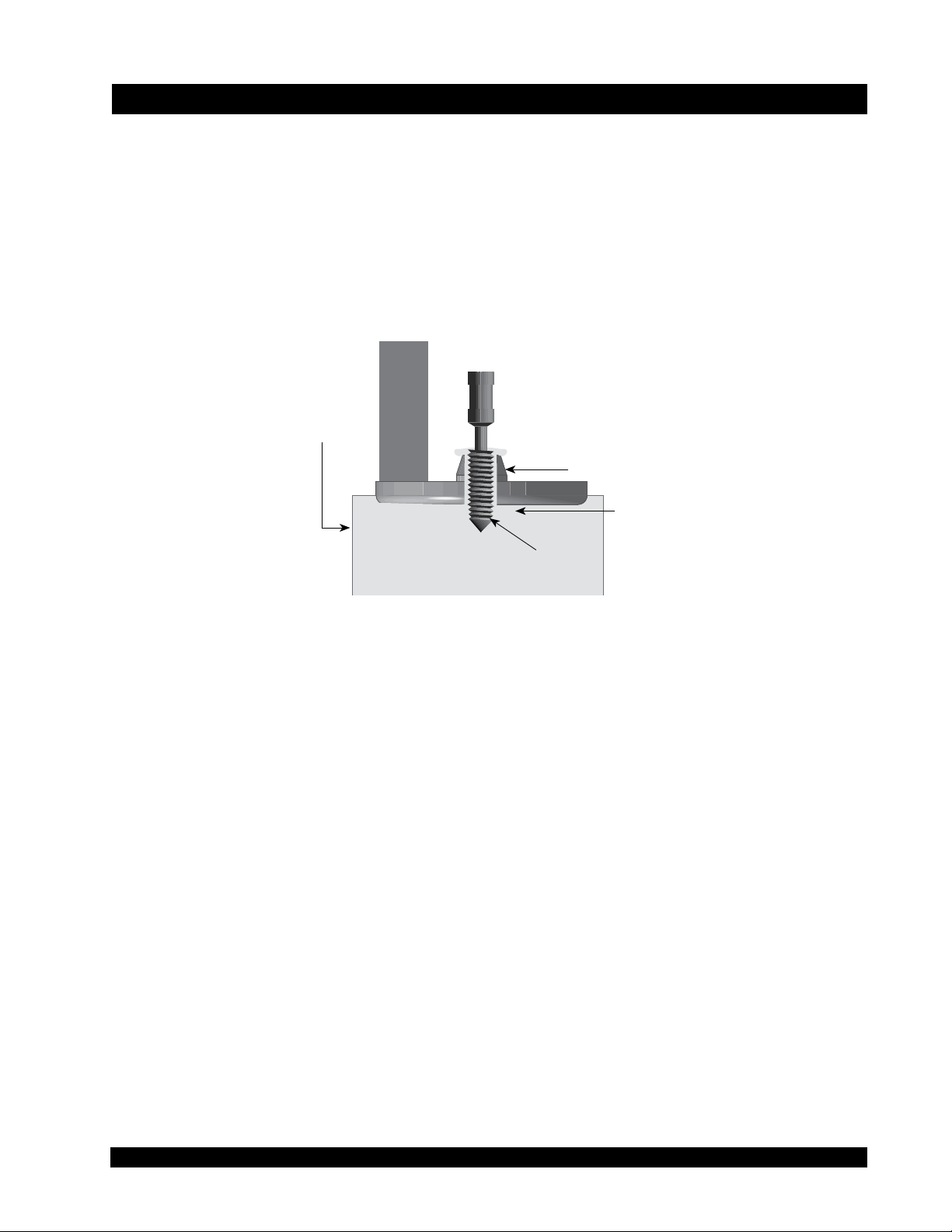
IV. INSTALLATION
Viscometer
Pivot Cup
Pointer Shaft
Clamp
Chamber
Spindle Nut
Spindle
Install the spiral spindle by lifting and holding the pointer shaft of the Viscometer/Rheometer while
screwing the spindle onto it. The threads are left-hand so the spindle must be turned to the left. Gently
lift the chamber over the spindle up against the pivot cup until it rests over the locating shoulder.
While holding the chamber in place, fasten the assembly clamp onto the pivot cup, thereby securing
the chamber in place. The thread in this case is right hand.
See Figure 2 which shows an assembly schematic for the Spiral Adapter.
Figure 2
Turn on the Viscometer/Rheometer and rotate the spindle at various speeds. Observe the spiral spindle
to make sure there is no interference with steady and even rotation. If the spindle does not run “true”,
then inspect the spindle and Viscometer/Rheometer shaft for straightness. Rotate the Viscometer/
Rheometer shaft without the spindle and conrm that the rotation is steady and even.
Notify Brookeld or your authorized Brookeld agent if you experience any difculty in performing
the above procedure.
The spiral spindle code number is 70. If you have a Brookeld digital viscometer or rheometer, which
does not contain this number, you must do the following:
Brookeld Engineering Labs., Inc. Page 8 Manual No. M93-270-D0812
Page 9

• For DV-I and Dial Viscometers, use the torque reading and manually convert to a viscosity
value using the table in Appendix A.
• For DV-II Viscometers, use the spindle 99 entry. Enter the following values:
SMC (Spindle Multiplier Constant) = 105
SRC (Shear Rate Constant) = .677
Note: Customers who use the Brookeld Spiral Adapter may need to have their Brookeld Viscometer/
Rheometer serviced before using this accessory device. All Brookeld digital viscometers/
rheometers with serial number lower than 24250 may not have proper alignment between
bearings and pivot cup. The same applies to all Brookeld dial viscometers.
This does not present any problem for normal Brookeld Viscometer/Rheometer use. However,
it may result in erroneous data when using the Spiral Adapter. For this reason, please return
your Brookeld Viscometer/Rheometer to Brookeld for servicing before using it with the
Spiral Adapter.
Brookeld Engineering Labs., Inc. Page 9 Manual No. M93-270-D0812
Page 10

V. OPERATION
V.1 Theory
The Spiral Adapter has an inner, threaded spindle surrounded by a concentric outer cylinder, as
shown previously in Figure 1. This combination causes the sample to be continuously pumped
up through the gap between the rotating spindle and the outer cylinder. The material reaches a
steady state of ow during which viscosity is measured.
At its various rotating speeds, the Brookeld Viscometer/Rheometer with the Spiral Adapter
provides viscosity data at different shear rates. The resulting rheogram from an up/down speed
ramp supplies important information on the pseudoplastic and thixotropic behavior of the test
material which may correlate with actual use in a process. In addition, the measurement method
may be less sensitive to sample handling and minor material variations than other viscosity
measuring methods.
V.2 Test Procedure
Ensure that the test material has been prepared properly in accordance with your prescribed
procedure. Lower the Spiral Adapter into the test uid as shown in Figure 1.
Start the Viscometer/Rheometer and allow it to run at high speed for quick ooding of the
chamber. This speed will vary with the nature of the test uid, but will typically be between 20
and 60 RPM for 2 to 10 minutes. The speed and time of the ood cycle may be an important
part of the test procedure. This is because the uid in the chamber will experience a shear
history before the start of the test.
When the chamber is ooded, you will observe test uid covering the top of the spindle. Stop
the Viscometer/Rheometer and allow a settling period per your dened procedure. Run the
viscosity test and record the data. An example of a test procedure is as follows:
Speed Duration
50 RPM 6 min.
0 RPM 2 min.
5 RPM 1 min.
10 RPM 1 min.
15 RPM 1 min.
20 RPM 1 min.
30 RPM 1 min.
A strip chart recorder can be used with digital Brookeld Viscometers/Rheometers during the
above procedure. An example of data output is shown in Figure 3.
Brookeld Engineering Labs., Inc. Page 10 Manual No. M93-270-D0812
Page 11

30
20
15
10
30405060
20
5
10
Tim
%
Figure 3
V.3 Data Gathering
Brookeld offers applications software for comprehensive data gathering with any IBM compatible
PC.
Brookeld software will capture and display the following data in tabular and/or graphical
format when used with the appropriate Brookeld Viscometer.
- Viscosity in centipoise (cP) or milliPascal seconds (mPa•s)
- % scale (Brookeld units)
- RPM
- Shear rate (sec-1)
- Shear stress (dynes/cm2 or N/m2)
- Temperature (°F or °C)
The data from a Brookeld dial reading, DV-E or DV-I+ (or DV-I) Viscometer can be manually
entered into one of our software applications.
In addition, the Brookeld Strip Chart Recorder (Model 1201) can be used to obtain a permanent
record of the Viscometer/Rheometer torque signal output, as shown in Figure 3. The Model
1202 can be used to record a second parameter, such as temperature, at the same time.
Contact Brookeld or an authorized dealer for more details on the appropriate software to use
with your viscometer/rheometer.
Brookeld Engineering Labs., Inc. Page 11 Manual No. M93-270-D0812
Page 12

V.4 Application Example - Solder Paste
Applying solder paste is a printing operation that shears the materials as the paste “rolls” on
the stencil surface. Solder paste typically shows pseudoplastic behavior (exponential decrease
in viscosity with increasing shear rate) as shown in Figure 4.
6
LOG VISCOSITY (cP)
10
10
Slope of Line =
Shear Sensitivity Factor
5
1
10 100
LOG RPM
VISCOSITY (cP)
7 x 10
6 x 10
5 x 10
4 x 10
5
5
5
5
05
10 15
20 25 30 35
RPM
40
45
50
55
Figure 4 Figure 5
A plot of viscosity vs. RPM on a log/log scale approximates a straight line as shown in Figure 5.
The slope of the line provides information about the shear thinning of the paste. The absolute
value of the slope is called the “shear sensitivity factor”. Experimental correlations of these
slope values to actual printing properties allow the user to establish acceptable ranges of the
shear sensitivity factor.
The plots shown in Figures 4 and 5 can be generated easily when using Brookeld application
software. There is a math model (IPC Paste Analysis) included in the software which converts
viscosity vs. RPM data (Figure 4) into a log/log plot (Figure 5) and automatically computes
the “shear sensitivity factor.”
V.5 Cleaning the Spiral Adapter
Support the chamber and remove the clamp. Carefully lower the chamber off the spindle. Soak
in appropriate solvent. Remove spindle by lifting the lower shaft and holding it rm. Turn
the spindle nut to the right (counter-clockwise) to remove. Clean by wiping and soaking in
appropriate solvent. A soft brush is provided to aid in cleaning the threads. This brush should
also be cleaned in solvent.
Brookeld Engineering Labs., Inc. Page 12 Manual No. M93-270-D0812
Page 13

APPENDIX A - Spiral Spindle Factors for Torque (% Scale) Measurements
Table A-1 applies to Brookeld Viscometer models with series designation LV, RV, HA, and HB.
The procedure for converting a torque value (% scale) into a viscosity value (cP) is accomplished
by multiplying the appropriate factor shown in Table A-1 by the torque reading on your Brookeld
Viscometer.
Spindle
Spiral Spindle Factors
Speeds
(RPM)
LV RV HA HB
0.3 3,280.0 35,000 70,000 280,000
0.5 1,968.0 21,000 42,000 168,000
0.6 1,640.0 17,500 35,000 140,000
1.0 984.0 10,500 21,000 84,000
1.5 656.0 7,000 14,000 56,000
2.0 492.0 5,250 10,500 42,000
2.5 394.0 4,200 8,400 33,600
3.0 328.0 3,500 7,000 28,000
4.0 246.0 2,625 5,250 21,000
5.0 197.0 2,100 4,200 16,800
6.0 164.0 1,750 3,500 14,000
10.0 98.4 1,050 2,100 8,400
12.0 82.0 875 1,750 7,000
20.0 49.2 525 1,050 4,200
30.0 32.8 350 700 2,800
50.0 19.7 210 420 1,680
60.0 16.4 175 350 1,400
100.0 9.8 105 210 840
Table A-1
The full scale viscosity measurement range (in cP or mPa•s) for any given speed is obtained by multiplying
the corresponding spiral spindle factor in the above table by 100.
Brookeld Engineering Labs., Inc. Page 13 Manual No. M93-270-D0812
Page 14

APPENDIX B - Online Help and Additional Resources
www.brookeldengineering.com**
The Brookeld website is a good resource for additional and self-help whenever you need it. Our
website offers a selection of “how-to” videos, application notes, conversion tables, instructional manuals,
material safety data sheets, calibration templates and other technical resources.
http://www.youtube.com/user/BrookeldEng
Brookeld has its own YouTube channel. Videos posted to our website can be found here as well as
other “home-made” videos made by our own technical sales group.
Viscosityjournal.com
Brookeld is involved with a satellite website that should be your rst stop in viscosity research. This
site serves as a library of interviews with experts in the viscosity eld as well as Brookeld technical
articles and conversion charts. Registration is required, so that you can be notied of upcoming
interviews and events, however, this information will not be shared with other vendors, institutions, etc..
Article Reprints
- Available in Print Only
- Brookeld has an extensive library of published articles relating to viscosity, texture and
powder testing. Due to copyright restrictions, these articles cannot be emailed. Please request
your hardcopy of articles by calling our customer service department directly or by emailing:
marketing@brookeldengineering.com
- Available Online
- Brookeld has a growing number of published articles that can be downloaded directly from
the Brookeld website. These articles can be found on our main site by following this path:
http://www.brookeldengineering.com/support/documentation/article reprints
More Solutions to Sticky Problems
Learn more about viscosity and rheology with our most popular publication. This informative booklet will
provide you with measurement techniques, advice and much more. It’s a must-have for any Brookeld
Viscometer or Rheometer operator. More Solutions is avaiable in print and also as a downloadable pdf
on the Brookeld website by following this path:
http://www.brookeldengineering.com/support/documentation
Training/Courses
Whether it is instrument-specic courses, training to help you better prepare for auditing concerns, or
just a better understanding of your methods, who better to learn from than the worldwide leaders of
viscosity measuring equipment? Visit our Services section on our website to learn more about training.
** Downloads will require you to register your name, company and email address. We respect your
privacy and will not share this information outside of Brookeld.
Brookeld Engineering Labs., Inc. Page 14 Manual No. M93-270-D0812
Page 15

APPENDIX C - Warranty Repair and Service
The Brookeld Spiral Adapter is guaranteed for one year from date of purchase against defects in materials
and workmanship. The Spiral Adapter must be returned to Brookeld Engineering Laboratories, Inc.
or the Brookeld dealer from whom it was purchased for no charge warranty service. Transportation
is at the purchaser’s expense. The Spiral Adapter should be shipped together with all components
originally provided with the system. If returning to Brookeld please contact us for a return authorization
number prior to shipping.
For repair or service in the United States return to:
Brookeld Engineering Laboratories, Inc.
11 Commerce Boulevard
Middleboro, MA 02346 U.S.A.
Telephone: (508) 946-6200 FAX: (508) 923-5009
www.brookeldengineering.com
For repair or service outside the United States consult Brookeld Engineering Laboratories, Inc. or the
dealer from whom you purchased the instrument.
For repair or service in the United Kingdom return to:
Brookeld Viscometers Limited
1 Whitehall Estate
Flex Meadow, Pinnacles West
Harlow, Essex CM19 5TJ, United Kingdom
Telephone: (44) 27/945 1774 FAX: (44) 27/945 1775
www.brookeld.co.uk
For repair or service in Germany return to:
Brookeld Engineering Laboratories Vertriebs GmbH
Hauptstrasse 18
D-73547 Lorch, Germany
Telephone: (49) 7172/927100 FAX: (49) 7172/927105
www.brookeld-gmbh.de
For repair or service in China return to:
Guangzhou Brookeld Viscometers and Texture Instruments Service Company Ltd.
Room C1, 5/F, Tianxing Building East Tower, No. 21, Zhongshan Yi Road, Yuexiu District
Guangzhou, 510600, P. R. China
Telephone: (86) 20/3760-0548 FAX: (86) 20/3760-0548
www.brookeld.com.cn
On-site service at your facility is also available from Brookeld. Please contact our Service
Department in the United States, United Kingdom, Germany or China for details.
Brookeld Engineering Labs., Inc. Page 15 Manual No. M93-270-D0812
 Loading...