


 Loading...
Bosch Installation Manual:
NEB

Table of Contents
Safety. . . . . . . . . . . . . . . . . . . . . . . . . . . . . . . . . . . . . . . . . . . . . . . . . . . . . . . . . . . . . . . . . . . . . . . . . . . . . 1
Important Safety Instructions . . . . . . . . . . . . . . . . . . . . . . . . . . . . . . . . . . . . . . . . . . . . . . 1
Installation. . . . . . . . . . . . . . . . . . . . . . . . . . . . . . . . . . . . . . . . . . . . . . . . . . . . . . . . . . . . . . . . . . . . . . . . . 2
Before You Begin . . . . . . . . . . . . . . . . . . . . . . . . . . . . . . . . . . . . . . . . . . . . . . . . . . . . . . . . . . . . . 2
Tools and Parts Needed. . . . . . . . . . . . . . . . . . . . . . . . . . . . . . . . . . . . . . . . . . . . . . . . . . 2
Parts Included. . . . . . . . . . . . . . . . . . . . . . . . . . . . . . . . . . . . . . . . . . . . . . . . . . . . . . . . . . 2
Overall Dimensions . . . . . . . . . . . . . . . . . . . . . . . . . . . . . . . . . . . . . . . . . . . . . . . . . . . . . 2
Cabinet Requirements . . . . . . . . . . . . . . . . . . . . . . . . . . . . . . . . . . . . . . . . . . . . . . . . . . . 2
Countertop Requirements . . . . . . . . . . . . . . . . . . . . . . . . . . . . . . . . . . . . . . . . . . . . . . . . 3
Power Requirements . . . . . . . . . . . . . . . . . . . . . . . . . . . . . . . . . . . . . . . . . . . . . . . . . . . . 3
Installation Procedure . . . . . . . . . . . . . . . . . . . . . . . . . . . . . . . . . . . . . . . . . . . . . . . . . . . . . . . . . . 4
Service. . . . . . . . . . . . . . . . . . . . . . . . . . . . . . . . . . . . . . . . . . . . . . . . . . . . . . . . . . . . . . . . . . . . . . . . . . . . 7
Before Calling Service . . . . . . . . . . . . . . . . . . . . . . . . . . . . . . . . . . . . . . . . . . . . . . . . . . . . . . . . . . 7
Product Data Plate . . . . . . . . . . . . . . . . . . . . . . . . . . . . . . . . . . . . . . . . . . . . . . . . . . . . . . . . . . . . 7
Questions?
1-800-944-2904
www.boschappliances.com
5551 McFadden Ave.
Huntington Beach, CA 92649
We look forward to hearing from you!
Safety
IMPORTANT SAFETY INSTRUCTIONS
READ AND SAVE THESE INSTRUCTIONS
INSTALLER: LEAVE THESE INSTRUCTIONS WITH THE APPLIANCE AFTER INSTALLATION IS COMPLETE. IMPORTANT: SAVE FOR THE LOCAL INSPECTOR'S USE.
Important Safety
Instructions
WARNING: Improper installation, adjustment, alteration, service or maintenance can cause injury or property damage. Refer to this manual. For assistance or additional information consult a qualified installer, service agency, or manufacturer.
•Have the installer show you the location of the circuit breaker or fuse. Mark it for easy reference.
•Be sure your appliance is properly installed and grounded by a qualified technician.
Equipment and Usage Safety Requirements
•Before you plug in an electrical cord, be sure all controls are in the OFF position.
•To eliminate the risk of burns or fire by reaching over heated surface units, cabinet storage space located above the surface units should be avoided. If cabinet storage is to be provided, the risk can be reduced by installing a range hood that projects horizontally a minimum of 5 inches (12.7 cm) beyond the bottom of the cabinet.
•This appliance has been tested in accordance with ANSI/UL 858 Standard for Safety for Household Electric Ranges and CAN/CSA-22.2 No.61 National Standard of Canada for Household Cooking Ranges. It is the responsibility of the owner and installer to determine if additional requirements and standards apply in specific installations.
English 1
Installation
Before You Begin
Tools and Parts
Needed
1.Phillips Head Screwdriver
2.Jigsaw
3.Scissors
4.Tape Measure
5.Aluminum Tape (for solid surface countertop installations only)
Parts Included
Overall Dimensions
1.Foam tape
2.Hold down brackets (4)
3.Clamping Screws, #10-32 x 2 1/2” (63.8 mm) (4)
4.Sheet Metal Screws, #8 x 3/8” (9.5 mm) (4)
5.Washers (4)
If parts are missing or damaged, call the number or write to the address listed inside the front cover.
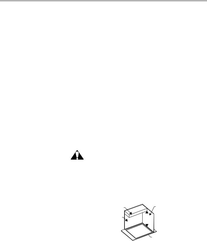
The cooktop’s overall dimensions are:
•Width 36" (91.4 cm)
•Depth 21-1/8" (536.9 mm)
•Height above countertop: 1/4" (6.35 mm)
•Overall height: 3-5/8” (92.58 mm)
Cabinet Requirements |
|
|
CAUTION: To eliminate the risk of burns or fire by reaching over |
|||
|
|
|
heated surface units, cabinet storage space located above the surface |
|||
|
|
|
||||
|
units should be avoided. If cabinet storage is to be provided, the risk can be |
|||||
|
reduced by installing a range hood that projects horizontally a minimum of 5 in. |
|||||
|
(127 mm) beyond the bottom of the cabinets. |
|||||
|
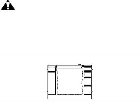
This unit is designed for installation in the countertop with zero clearance to adja- |
|||||
|
cent walls and projecting surfaces constructed of combustible materials. A 30- |
|||||
|
inch (762 mm) minimum clearance is required between the top of the cooktop and |
|||||
|
|
|
|
|
|
|
|
|
|
Cabinet Bottom |
|
|
Building Side |
|
|
|
(Unprotected) |
|
|
|
|
|
|
|
|
Wall |
|
|
|
|
|
|
|
|
|
|
|
Building Back |
|
|
|
|
|
|
|
|
|
|
|
|
|
30” |
min. |
||
|
|
|
Wall |
|||
|
|
|
(762 |
mm) |
||
|
|
|
|
|||
|
|
|
|
|
|
Cooking |
|
|
|
|
|
|
|
|
|
|
|
|
|
Surface |
|
|
|
|
|
|
|
|
|
|
|
|
|
Figure 1: Cabinet Requirements |
|
the bottom of an unprotected cabinet. A 24-inch (610 mm) minimum distance is |
|||||
|
necessary when the bottom of the wood or metal cabinet is protected by not less |
|||||
|
than 1/4 inch (6.35 mm) of a flame retardant material covered with not less than |
|||||
English 2 |
|
|
|
|
|
|
Countertop
Requirements
Installing Over an Oven
Power Requirements
No. 28 MSG sheet steel, 0.015-inch (0.4 mm) thick stainless steel, 0.024-inch (0.6 mm) aluminum, or 0.020-inch (0.5 mm) thick copper. Flame retardant materials bear the mark:
UNDERWRITERS LABORATORIES INC.
CLASSIFIED
MINERAL AND FIBER BOARDS
SURFACE BURNING CHARACTERISTICS
Followed by the flame spread and smoke ratings, these designations are shown as “FHC (Flame Spread) / (Smoke Developed)”. Materials with “O” flame spread ratings are flame retardant. Local codes may allow other flame spread ratings.
The minimum horizontal clearance from the sides and back edge of the cooktop to the adjacent vertical combustible walls is 0 (zero) inches.
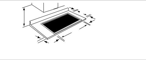
Countertop cutout dimensions are shown in the figure and table below. A range of cutout dimensions is shown because the actual dimensions depend upon whether the installation is for replacement, new construction, or installation in a solid surface countertop material, such as Surel™ or Corian®.
Solid surface countertops require larger cutouts, use of heat reflective tape and rounded corners. Always consult the countertop manufacturer for specific installation instructions. For solid surface countertop installations, use the maximum cutout dimensions below and consult the surface manufacturer for specific cutting instructions.
30" (76.2 cm) Minumum
A
2-1/2"
(63,8 mm) Setback Distance
(from front edge of countertop to front edge of cutout.)
1" (25.4 mm) Flat Area
 B 1-3/4" (44.5 mm) Flat Area
1" (25.4 mm) Flat Area
C
1" (25.4 mm) Flat Area
|
|
|
Figure 2: Countertop Requirements |
|
Table 1: Standard Countertop Cutout Dimensions |
||||
|
|
|
|
|
Cutout |
Minimum Dimension |
Maximum Dimension |
|
|
Area |
inches / (mm) |
inches / (mm) |
|
|
|
|
|
|
|
A |
2 1/2” |
(63.5 mm) setback |
2 1/2” (63.5 mm) setback |
|
|
|
distance |
distance |
|
|
|
|
|
|
B |
19 |
7/8” / (505 mm) |
20” / (508 mm) |
|
|
|
|
|
|
C |
34 |
3/4” / (883 mm) |
34 7/8” / (886 mm) |
|
|
|
|
|
|
This unit is not approved for installation over an oven.
Power Supply is dual rated: 240 Volts or 208 Volts, 4 wire, 60 Hz, with the following circuit breaker requirements:
English 3
•40 Amp circuit breaker
•240 Volt, 4 Wire, 60 Hz / 208 Volt, 4 Wire, 60 Hz
Connect only to a 4-wire 120/240 or 120/208 volt AC system. The neutral is required for the operation of this appliance and an independent ground is required.
Installation Procedure
|
WARNING: To avoid electrical shock hazard, before installing the |
|
cooktop, switch power off at the service panel and lock the panel to |
|
prevent the power from being switched on accidentally. |
1) Prepare Power Supply |
• Install a junction box (not supplied), below the counter top within 3 feet (91.4 |
|
cm) of flexible conduit (supplied) located at the left rear corner of the cooktop |
|
rough-in box. |
|
• Plan the installation of the unit so the location of the junction box is within 3 |
|
feet (91.4 cm) of the left rear of the cooktop bottom. |
|
• The junction box must be accessible from the front of the cabinet. |
|
Conduit |
|
(approx 3 ft.(91.4 cm)) |
|
12” |
|
(30.4 cm) |
|
(approx) |
|
“j” Box |
|
Figure 3: Junction Box Installation |
2)Seal the Cooktop with Foam Tape
Foam tape is provided to seal the cooktop edges to the countertop. Seal the cooktop with the foam tape as follows:
Important: Apply the tape starting at a middle point of any edge of the cooktop. Do not start at any corner of the cooktop.
1.Turn cooktop upside down.
2.Start at the middle of the front, back, or either end of the cooktop and apply the one continuous piece of tape approximately 1/16” (1.6 mm) from the glass edges. Use tape around the entire glass perimeter.
3.Overlap the end of the tape with the start of the tape and cut through the center of the overlapping pieces with the scissors to ensure the ends of the tape create a tight-fitting butt joint.
English 4
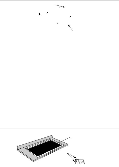
4. Remove excess tape where tape ends butt.
Swivel Conduit Connector
|
Foam |
|
Tape |
|
Seal |
|
Start tape in middle |
|
of a side, not on a corner |
|
|
|
Figure 4: Seal the Cooktop |
3) Prepare the Countertop |
The cutout dimensions depend upon whether the installation is for replacement, |
|
new construction, or installation in a solid surface countertop material, such as |
|
Surel™, Corian® etc. Countertops made from natural (i.e. granite and marble) or |
|
SOLID SURFACE MATERIALS, such as Surell™ and Corian® require larger cut- |
|
outs, use of heat reflective tape and rounded corners. Always consult the counter- |
|
top manufacturer for specific instructions. |
|
For Standard Countertops |
|
1. Cut out the countertop according to the dimensions shown in Table 1. |
For Solid Surface Countertops
1.Use the maximum cutout dimensions in Table 1 and consult the countertop surface manufacturer for specific cutting instructions.
2.Round the cutout corners per instructions from countertop manufacturer.
3.Apply heat reflective tape (such as Scotch® Aluminum Foil Tape #425 or #427) around the cutout so that it folds over the top and side surfaces. Be sure the tape extends beyond the outermost flange of the cooktop. All corners should also be covered with tape.
shows location of aluminum reflective tape
tape top and vertical sides of cutout
Figure 5: Applying Heat Reflective Tape for Solid Surface Installation
4)Secure Cooktop to Countertop The cooktop should be secured to countertop using hold-down brackets provided.
1.Turn cooktop upside down and attach the brackets to the burner box using the washers and screws. Use the unthreaded screw holes for attaching the bracket to the cooktop. The threaded screw holes are needed for the clamping screws that attach the bracket to the countertop in a later step.
2.Rotate the mounting brackets sideways to allow enough clearance for the cooktop to be inserted through the cutout opening.
3.Place cooktop into cutout. Center cooktop in the cutout to ensure adequate clearance between the burner box and countertop edge. (A light pencil mark along the center of front edge and side edge of cooktop and counter will aid in the positioning of the cooktop in the center.)
English 5
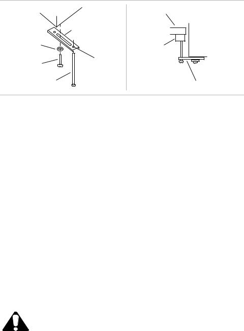
4.Place a wood block on the underside of the cabinet where the adjusting screw will meet the countertop. The adjusting screws will tighten down on the wood block to clamp the cooktop tightly to the countertop. This will protect the countertop surface from damage.
burner box |
countertop |
|
bracket |
|
|
washer |
burner box |
|
wood block |
||
|
||
screw |
threaded |
|
screw hole |
||
|
||
clamping screw |
bracket |
|
|
Figure 6: Secure the Cooktop |
5.Rotate brackets into proper position and insert clamping screws into the brackets.
6.Tighten clamping screws into wood blocks to secure cooktop to countertop.
5)Trim Excess Aluminum Tape Trim excess aluminum tape from along the frame edges. BE CAREFUL not to
|
(solid surface countertop |
scratch the countertop. |
|
|
installation only) |
|
|
6) |
Electrical Connection |
1. |
Attach flexible conduit to the junction box. |
|
|
2. |
Connect the cooktop lead wires to the junction box supply wires in proper |
|
|
|
phase: for all models, connect black (L1) to black, red (L2) to red, white wire |
|
|
|
to neutral, green wire to ground. |
|
|
Note: The ground wire and neutral wire are twisted together at the factory. For |
|
|
|
proper operation, untwist and connect to the required four wire system. |
|
|
|
NOTE: If the cooktop is installed and connected as specified above, it will be com- |
|
|
|
pletely grounded in compliance with the National Electrical Code. |
|
7) |
Final Check |
1. |
Remove everything from the cooktop surface and apply glass ceramic cook- |
|
|
|
top cleaner (packaged with cooktop) as directed in Use and Care Manual. |
|
|
2. |
Turn on power supply. |
|
|
3. |
Test operation. |
CAUTION: Your cooktop surface needs to be cleaned daily. Refer to the Use and Care Manual before using it for the first time.
English 6
Service
Before Calling
Service
Product Data
Plate
If the elements do not heat or if the indicator “on” light does not glow, check the power source to see if a fuse has blown or if the circuit breaker has tripped.
Refer to the Warranty in the Use and Care Manual. See Use and Care Manual for troubleshooting information.
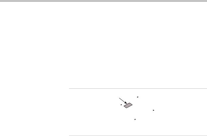
The data plate shows the model and serial number of your cooktop. It is located in the center front area of the rough-in box, underneath the cooktop.
Keep your invoice or escrow papers for warranty validation if service is needed.
Data Plate
Figure 7: Data Plate Location
English 7
Loading...