

Bosch DIVAR 2000, DIVAR 3000, DIVAR 5000 Operation Manuals
DIVAR 2000 / DIVAR 3000 / DIVAR 5000
Network/Hybrid Video Recorder
en Operation Manual
Available from A1 Security Cameras
www.a1securitycameras.com email: sales@a1securitycameras.com

Available from A1 Security Cameras
www.a1securitycameras.com email: sales@a1securitycameras.com

DIVAR 2000 / DIVAR 3000 / DIVAR
Table of Contents | en 3
5000
Table of contents
1
Safety 6
1.1 Important safety instructions 6
1.2 FCC and UL 8
2
Short information 9
3
System overview 10
4
Installation 11
4.1 Unpacking 11
4.1.1 Package contents 11
4.2 Make connections 12
4.2.1 Back panel connectors DIVAR network 2000/3000 (no PoE) 13
4.2.2 Back panel connectors DIVAR network 2000 (8 PoE) 14
4.2.3 Back panel connectors DIVAR network 2000/3000 (16 PoE) 15
4.2.4 Back panel connectors DIVAR network 5000 (no PoE) 16
4.2.5 Back panel connectors DIVAR network 5000 (16 PoE) 17
4.2.6 Back panel connectors DIVAR hybrid 3000 18
4.2.7 Back panel connectors DIVAR hybrid 5000 19
4.2.8 Browser setup 19
4.3 Powering up 20
4.4 Startup wizard 20
4.5 Login 21
4.6 Logout/Shutdown 21
5
Hardware setup 22
5.1 Keyboard connection (only DIVAR 5000 models) 22
5.1.1 Connect using RJ11 adapter 22
5.1.2 Connect wires directly 23
5.2 RS485 port connection (only hybrid models) 24
5.3 RS232 port connections 25
5.4 Alarm I/O connections 25
6
Settings 27
6.1 System 27
6.1.1 General 27
6.1.2 Playback 28
6.1.3 Display 28
6.1.4 Serial port 29
6.1.5 Account 29
6.1.6 Service 31
6.2 Network 33
6.2.1 Connection 33
6.2.2 DDNS 34
6.2.3 Mobile 34
6.2.4 UPnP 34
6.2.5 PPPoE 34
6.2.6 SNMP 34
6.2.7
Email 35
6.2.8 Storage 35
6.2.9 IP filter 36
6.3 Camera 37
Bosch Security Systems Operation Manual 2016.09 | v1.0 | AM18-Q0717
Available from A1 Security Cameras
www.a1securitycameras.com email: sales@a1securitycameras.com

DIVAR 2000 / DIVAR 3000 / DIVAR
4 en | Table of Contents
5000
6.3.1 Detection 37
6.3.2 Configuration 37
6.3.3 Recording 38
6.4 Alarm 39
6.4.1 Motion detect 39
6.4.2 Video loss 40
6.4.3 Input alarm 41
6.4.4 System alarm 41
6.4.5 Alarm Out 41
6.5 Schedule 42
6.5.1 Weekdays and Holidays 42
6.6 Storage 43
6.6.1 HDD manage 43
6.6.2 Recording 43
7
Operation 44
7.1 User controls and menus 44
7.1.1 Mouse Controls 44
7.1.2 Front panel controls 45
7.1.3 Remote control 47
7.1.4 Quick menu 50
7.1.5 Main menu 50
7.2 Live screen 50
7.2.1 Live mode 51
7.2.2 Pan/Tilt/Zoom 52
7.2.3 Sequence 52
7.2.4 Monitor A 53
7.2.5 Monitor B (only for DIVAR 5000 models) 53
7.3 Playback 54
7.3.1 Export 61
7.3.2 Export snapshot 61
7.4 Info 61
7.4.1 System Alarm 61
7.4.2 System Health 61
7.4.3 System Version 62
7.4.4 Network Online users 62
7.4.5 Network Load 62
7.4.6 Network Test 62
7.4.7 HDD General 62
7.4.8 HDD Health 63
7.4.9 Log 63
7.5 Export 64
7.6 Event search 64
8
Archive Player operation 66
8.1 Getting started
66
8.1.1 System requirements 66
8.1.2 Installation 66
8.1.3 Starting the Player 66
8.2 Authentication (checking watermark) 69
8.3 Export file 69
2016.09 | v1.0 | AM18-Q0717 Operation Manual Bosch Security Systems
Available from A1 Security Cameras
www.a1securitycameras.com email: sales@a1securitycameras.com

DIVAR 2000 / DIVAR 3000 / DIVAR
5000
Table of Contents | en 5
8.4 Configuration 70
9
Web Client Software 71
9.1 Getting started 71
9.2 How to log on 71
9.3 Web client live window 71
9.3.1 Playback mode 71
9.3.2 Event search 71
9.3.3 Export 72
9.3.4 Setting 72
9.3.5 Info 72
9.3.6 Logout 72
10
Troubleshooting 73
11
Maintenance 77
11.1 Insert DIVAR 5000 in rack 77
11.2 Replace internal battery 77
11.3 Install HDD 77
11.4 Install DVD 78
12
Decommissioning 79
12.1 Transfer 79
12.2 Disposal 79
13
Technical data 80
14
Appendices 82
14.1 Software licenses 82
14.1.1 Bosch software 82
14.1.2 Other licenses — copyright notices 82
14.1.3 Warranties and disclaimer of warranties 83
14.2 DVD Compatibility 83
14.3 HDD Compatibility 84
Bosch Security Systems Operation Manual 2016.09 | v1.0 | AM18-Q0717
Available from A1 Security Cameras
www.a1securitycameras.com email: sales@a1securitycameras.com
1
1.1
DIVAR 2000 / DIVAR 3000 / DIVAR
6 en | Safety
5000
Safety
!
Warning!
Indicates a hazardous situation which, if not avoided, could result in death or serious injury.
!
Caution!
Indicates a hazardous situation which, if not avoided, could result in minor or moderate
injury.
Notice!
Indicates a situation which, if not avoided, could result in damage to the equipment or
environment, or data loss.
Important safety instructions
Video loss - Video loss is inherent to digital video recording; therefore, Bosch Security
Systems cannot be held liable for any damage that results from missing video information.
To minimize the risk of losing information, we recommend multiple, redundant recording
systems, and a procedure to back up all analog and digital information.
Accessories - Do not place this unit on an unstable stand, tripod, bracket,
or mount. The unit may fall, causing serious injury and/or serious damage to
the unit. Use only with the cart, stand, tripod, bracket, or table specified by
the manufacturer. When a cart is used, use caution and care when moving
the cart/apparatus combination to avoid injury from tip-over. Quick stops,
excessive force, or uneven surfaces may cause the cart/unit combination to
overturn. Mount the unit per the manufacturer's instructions.
Read, follow, and retain for future reference all of the following safety instructions. Heed all
warnings on the unit and in the operating instructions before operating the unit.
1. Cleaning - Unplug the unit from the outlet before cleaning. Follow any instructions
provided with the unit. Generally, using a dry cloth for cleaning is sufficient but a moist,
fluff-free cloth or leather shammy may also be used. Do not use liquid cleaners or aerosol
cleaners.
2. Heat Sources - Do not install the unit near any heat sources such as radiators, heaters,
stoves, or other equipment (including amplifiers) that produce heat.
3. Ventilation - Any openings in the unit enclosure are provided for ventilation to prevent
overheating and ensure reliable operation. Do not block or cover these openings. Do not
place the unit in an enclosure unless proper ventilation is provided, or the manufacturer's
instructions have been adhered to.
4. Water - Do not use this unit near water, for example near a bathtub, washbowl, sink,
laundry basket, in a damp or wet basement, near a swimming pool, in an outdoor
installation, or in any area classified as a wet location. To reduce the risk of fire or
electrical shock, do not expose this unit to rain or moisture.
2016.09 | v1.0 | AM18-Q0717 Operation Manual Bosch Security Systems
Available from A1 Security Cameras
www.a1securitycameras.com email: sales@a1securitycameras.com

DIVAR 2000 / DIVAR 3000 / DIVAR
Safety | en 7
5000
5. Object and liquid entry - Never push objects of any kind into this unit through openings
as they may touch dangerous voltage points or short-out parts that could result in a fire
or electrical shock. Never spill liquid of any kind on the unit. Do not place objects filled
with liquids, such as vases or cups, on the unit.
6. Lightning - For added protection during a lightning storm, or when leaving this unit
unattended and unused for long periods, unplug the unit from the wall outlet and
disconnect the cable system. This will prevent damage to the unit from lightning and
power line surges.
7. Controls adjustment - Adjust only those controls specified in the operating instructions.
Improper adjustment of other controls may cause damage to the unit. Use of controls or
adjustments, or performance of procedures other than those specified, may result in
hazardous radiation exposure.
8. Overloading - Do not overload outlets and extension cords. This can cause fire or
electrical shock.
9. Power supply cord and plug protection - Power supply cords should be routed so that
they are not likely to be walked on or pinched by items placed upon or against them,
playing particular attention to cords and plugs, convenience receptacles, and the point
where they exit from the appliance.
10. Power disconnect - Units have power supplied to the unit whenever the power cord is
inserted into the power source. The power cord plug is the main power disconnect device
for switching off the voltage for the unit.
11. Power sources - Operate the unit only from the type of power source indicated on the
label. Before proceeding, be sure to disconnect the power from the cable to be installed
into the unit.
12. Servicing - Do not attempt to service this unit yourself. Opening or removing covers may
expose you to dangerous voltage or other hazards. Refer all servicing to qualified service
personnel.
13. Damage requiring service - Unplug the power unit from the main AC power source and
refer servicing to qualified service personnel when any damage to the equipment has
occurred, such as:
– the power supply cord or plug is damaged;
– exposure to moisture, water, and/or inclement weather (rain, snow, etc.);
– liquid has been spilled in or on the equipment;
– an object has fallen into the unit;
– unit has been dropped or the unit cabinet is damaged;
– unit exhibits a distinct change in performance;
– unit does not operate normally when the user correctly follows the operating
instructions.
14. Replacement parts - Be sure the service technician uses replacement parts specified by
the manufacturer, or that have the same characteristics as the original parts.
Unauthorized substitutions could void the warranty and cause fire, electrical shock, or
other hazards.
15. Safety check - Safety checks should be performed upon completion of service or repairs
to the unit to ensure proper operating condition.
16. Installation - Install in accordance with the manufacturer's instructions and in accordance
with applicable local codes.
17. Attachments, changes or modifications - Only use attachments/accessories specified by
the manufacturer. Any change or modification of the equipment, not expressly approved
by Bosch, could void the warranty or, in the case of an authorization agreement, authority
to operate the equipment.
Bosch Security Systems Operation Manual 2016.09 | v1.0 | AM18-Q0717
Available from A1 Security Cameras
www.a1securitycameras.com email: sales@a1securitycameras.com

1.2
DIVAR 2000 / DIVAR 3000 / DIVAR
8 en | Safety
5000
FCC and UL
FCC & ICES Information
This equipment has been tested and found to comply with the limits for a Class B digital
device, pursuant to part 15 of the FCC Rules. These limits are designed to provide reasonable
protection against harmful interference in a residential installation. This equipment
generates, uses, and can radiate radio frequency energy and, if not installed and used in
accordance with the instructions, may cause harmful interference to radio communications.
However, there is no guarantee that interference will not occur in a particular installation. If
this equipment does cause harmful interference to radio or television reception, which can be
determined by turning the equipment off and on, the user is encouraged to try to correct the
interference by one or more of the following measures:
– reorient or relocate the receiving antenna;
– increase the separation between the equipment and receiver;
– connect the equipment into an outlet on a circuit different from that to which the receiver
is connected;
– consult the dealer or an experienced radio/TV technician for help.
Intentional or unintentional modifications, not expressly approved by the party responsible for
compliance, shall not be made. Any such modifications could void the user's authority to
operate the equipment. If necessary, the user should consult the dealer or an experienced
radio/television technician for corrective action.
The user may find the following booklet, prepared by the Federal Communications
Commission, helpful: How to Identify and Resolve Radio-TV Interference Problems. This
booklet is available from the U.S. Government Printing Office, Washington, DC 20402, Stock
No. 004-000-00345-4.
UL Disclaimer
Underwriter Laboratories Inc. ("UL") has not tested the performance or reliability of the
security or signaling aspects of this product. UL has only tested fire, shock and/or casualty
hazards as outlined in Standard(s) for Safety for Information Technology Equipment, UL
60950-1 . UL Certification does not cover the performance or reliability of the security or
signaling aspects of this product.
UL MAKES NO REPRESENTATIONS, WARRANTIES, OR CERTIFICATIONS WHATSOEVER
REGARDING THE PERFORMANCE OR RELIABILITY OF ANY SECURITY OR SIGNALING-RELATED
FUNCTIONS OF THIS PRODUCT.
2016.09 | v1.0 | AM18-Q0717 Operation Manual Bosch Security Systems
Available from A1 Security Cameras
www.a1securitycameras.com email: sales@a1securitycameras.com

2
DIVAR 2000 / DIVAR 3000 / DIVAR
Short information | en 9
5000
Short information
This manual has been compiled with great care and the information it contains has been
thoroughly verified. The text was correct at the time of printing, however, the content can
change without notice. Bosch Security Systems accepts no liability for damage resulting
directly or indirectly from faults, incompleteness or discrepancies between this manual and
the product described.
Trademarks
All hardware and software product names used in this document are likely to be registered
trademarks and must be treated accordingly.
More information
For more information please contact the nearest Bosch Security Systems location or visit
www.boschsecurity.com
http://www.boschsecurity.com/catalog_overview.htm
Bosch Security Systems Operation Manual 2016.09 | v1.0 | AM18-Q0717
Available from A1 Security Cameras
www.a1securitycameras.com email: sales@a1securitycameras.com

3
DIVAR 2000 / DIVAR 3000 / DIVAR
10 en | System overview
5000
System overview
The recorder can be connected to cameras that use the latest H264 high-resolution video
technology and state-of-the-art compression techniques. These advanced technologies,
coupled with efficient network data transmission, deliver the high security and reliability
required for modern surveillance systems.
Simultaneous remote or local monitoring, recording, archiving and playback are guided by
simple menu selections and operator commands. The recorders can be installed with optional
HDDs for video storage; plus a DVD burner for video export.
2016.09 | v1.0 | AM18-Q0717 Operation Manual Bosch Security Systems
Available from A1 Security Cameras
www.a1securitycameras.com email: sales@a1securitycameras.com
4
DIVAR 2000 / DIVAR 3000 / DIVAR
Installation | en 11
5000
Installation
Notice!
Use proper surge suppression on cables that are routed outdoors, or close to large inductive
loads or electrical mains supply cables.
!
Caution!
Installation should only be performed by qualified service personnel in accordance with the
National Electrical Code (NEC 800 CEC Section 60) or applicable local codes.
To get the unit operational, perform the following quick install steps:
1. Carefully unpack the recorder from its shipping packaging – see Unpacking.
2. Make all required hardware connections – see ‘Make Connections’.
3. Power up the system – see Powering Up.
4. Log in – see Login.
5. Correctly configure your system software with the Startup wizard (this appears the first
time the unit is started) – see Startup Wizard.
After completing this initial setup, the system is ready to run and will show a live view of the
camera image(s). If required, you can alter the settings later using the menus and/or factory
defaults, or you can run the Startup wizard again.
4.1 Unpacking
This equipment should be unpacked and handled with care. If an item appears to have been
damaged in shipment, notify the shipper immediately.
Verify that all parts are included. If any items are missing, notify your Bosch Security Systems
Sales or Customer Service Representative.
The original packaging is the safest container in which to transport the unit and can be used if
returning the unit for service.
4.1.1 Package contents
Qty Component
1 Recorder
1 Optical disc containing software licenses and user documentation
2 Power supply cables (120VAC US type; 230VAC Euro type)
1 External power supply adapter (only for DIVAR 2000/3000 network (non-PoE)
models and DIVAR 3000 hybrid models)
Terminal connector blocks
1 19” mounting set including brackets and screws (only on DIVAR 5000 models)
1 Hard disk mounting kit (including SATA cables, brackets and screws)
1 Optical USB mouse
1 IR remote Control with 2 AA (1.5 V) batteries
1 Ground screw
Bosch Security Systems Operation Manual 2016.09 | v1.0 | AM18-Q0717
Available from A1 Security Cameras
www.a1securitycameras.com email: sales@a1securitycameras.com
4.2
DIVAR 2000 / DIVAR 3000 / DIVAR
12 en | Installation
5000
Qty Component
1 Split cable for loop through to 25-pin D-connector (only for DIVAR 5000 hybrid
models)
1 RJ11 adapter cable to connect Bosch Intuikey keyboard
Installation guides for Recorder, HDD, plus safety instructions
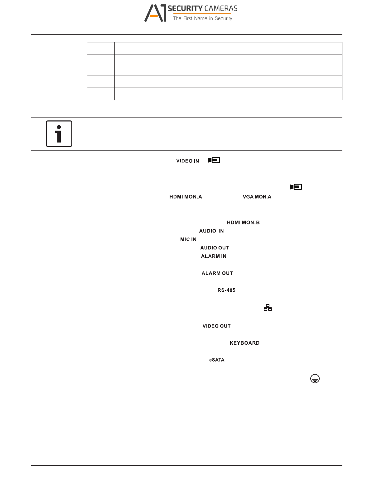
Make connections
Notice!
Use only PoE approved devices.
1. Connect the cameras to the or connectors.
– If using PoE connector, power is supplied to the camera via the Ethernet cable
compliant with the Power-over-Ethernet standard.
– Use an external switch to connect more cameras to a single RJ45
port.
2. Connect monitor A to the output, or the output.
3. Connect the USB mouse to a USB port (back or front panel).
Optional connections (depending on model)
1. Connect a second dual monitor to the optional connector.
2. Connect up to 4 audio signals to the RCA (CINCH) inputs.
3. Connect 1 microphone to the RCA (CINCH) input.
4. Connect 1 RCA (CINCH) output from to the monitor or an audio amplifier.
5. Connect up to 16 alarm inputs to the connector (via the supplied terminal
blocks) – see description in Hardware setup.
6. Connect up to 6 alarm outputs to the connector (via the supplied terminal
blocks) – see description in Hardware setup.
7. Connect a pan/tilt/zoom control unit to the (only for hybrid models) – see
description in Hardware setup.
8. Connect to your network via the RJ45 ETHERNET connector (use Shielded Twisted
Pair Category 5e cable).
9. Connect extra video out cables to the ports if loop through is required to other
devices (only for DIVAR 5000 hybrid).
10. Connect a Bosch Intuikey keyboard cable to the connector using the supplied
adaptor (only for DIVAR 5000) – see description in Hardware setup.
11. Connect an eSATA storage device to the connector (only for DIVAR 5000).
12. Connect the DIVAR to an approved ground point. Use the ground screw (supplied in the
accessory bag) to attach a ground cable to the DIVARback panel ground point
.
2016.09 | v1.0 | AM18-Q0717 Operation Manual Bosch Security Systems
Available from A1 Security Cameras
www.a1securitycameras.com email: sales@a1securitycameras.com
4.2.1
DIVAR 2000 / DIVAR 3000 / DIVAR
Installation | en 13
5000
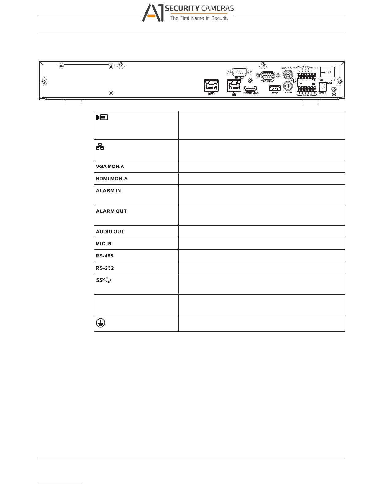
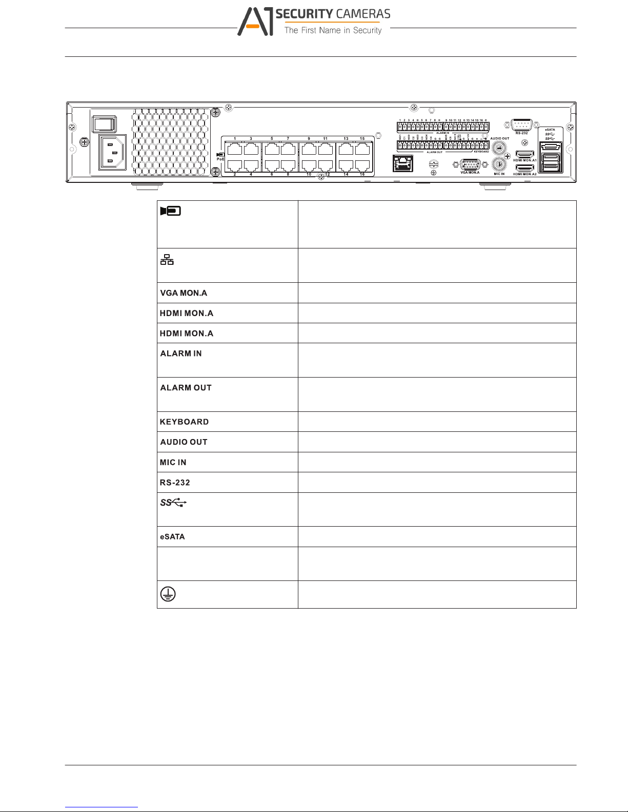
Back panel connectors DIVAR network 2000/3000 (no PoE)
RJ45 video input for max. 32 IP cameras (max. 16 IP cameras
for DIVAR 2000) connected via external switch (optional with
DHCP configuration)
RJ45 Ethernet connection (10/100/1000Base-T according to
IEEE802.3)
1 D-SUB (Monitor output)
1 HDMI (Monitor output)
4 screw terminal inputs, cable diameter AWG26‑16 (0.13–
1.5 mm)
2 screw terminal outputs, cable diameter AWG26‑16 (0.13–
1.5 mm)
1 RCA (Audio output)
1 RCA (Audio input)
Screw terminal output
DB9 male, 9-pin D-type
One USB (3.0) connector for mouse or USB memory device;
one USB (2.0) also on front panel
Power input with On/Off
switch
12 VDC (5 A)
AC input adapter: 100~240 VAC, 50-60 Hz, 1.5 A
Ground connection
Bosch Security Systems Operation Manual 2016.09 | v1.0 | AM18-Q0717
Available from A1 Security Cameras
www.a1securitycameras.com email: sales@a1securitycameras.com
4.2.2
DIVAR 2000 / DIVAR 3000 / DIVAR
14 en | Installation
5000
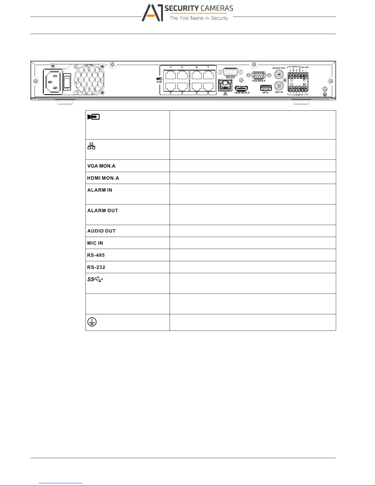
Back panel connectors DIVAR network 2000 (8 PoE)
PoE
Max. 8 RJ45 PoE ports (115 W; 25.5 W max. per port)
connected with DHCP configuration (maximum 16 IP
channels possible)
RJ45 Ethernet connection (10/100/1000Base-T according to
IEEE802.3)
1 D-SUB (Monitor output)
1 HDMI (Monitor output)
4 screw terminal inputs, cable diameter AWG26‑16 (1.29–
0.4 mm)
2 screw terminal outputs, cable diameter AWG26‑16 (1.29–
0.4 mm)
1 RCA (Audio output)
1 RCA (Audio input)
Screw terminal output
DB9 male, 9-pin D-type (for service)
One USB (3.0) connector for mouse or USB memory device;
One USB (2.0) also on front panel
Power input with On/Off
switch
100~240 VAC, 50-60 Hz, 3.5 A, 190 W
Ground connection
2016.09 | v1.0 | AM18-Q0717 Operation Manual Bosch Security Systems
Available from A1 Security Cameras
www.a1securitycameras.com email: sales@a1securitycameras.com
4.2.3
DIVAR 2000 / DIVAR 3000 / DIVAR
Installation | en 15
5000
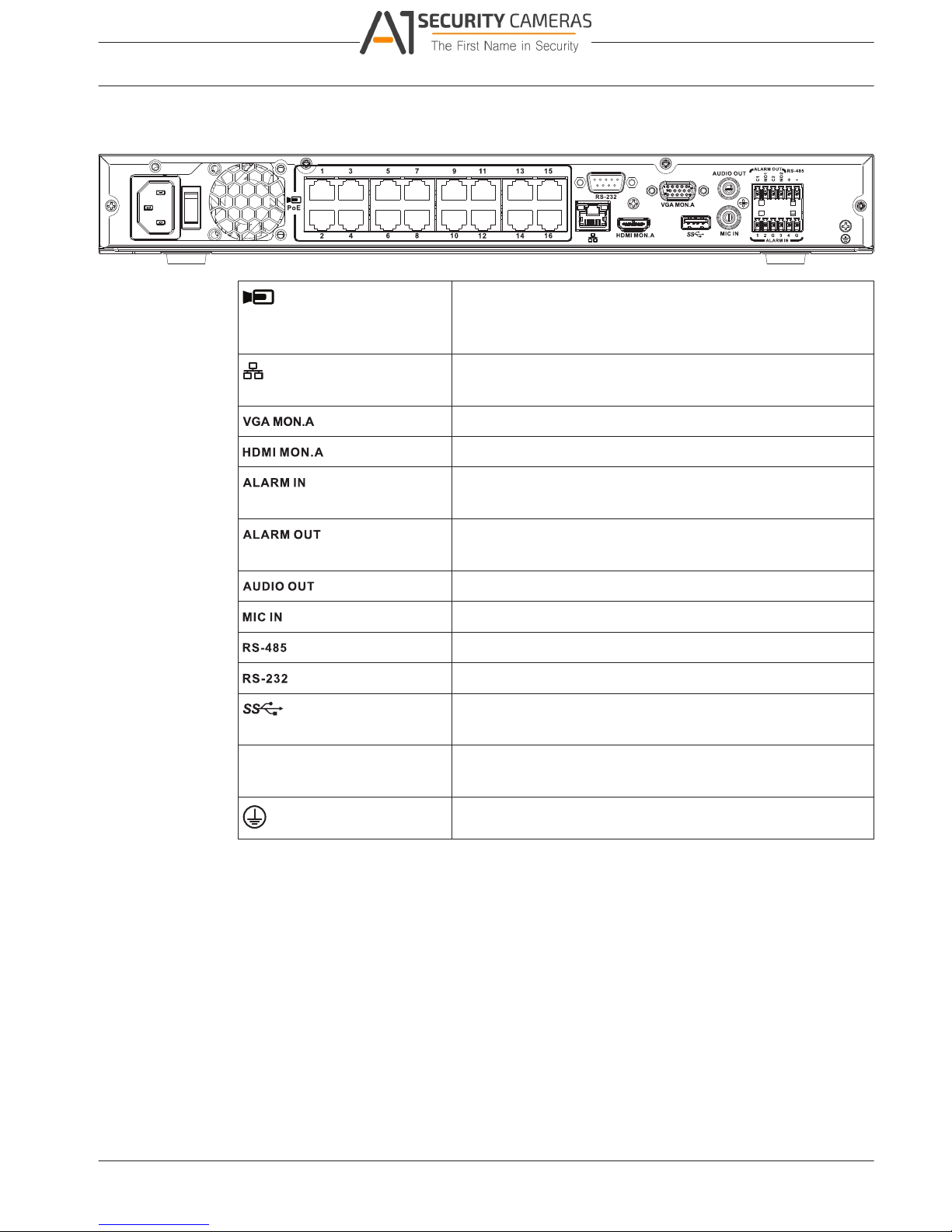
Back panel connectors DIVAR network 2000/3000 (16 PoE)
PoE
Max. 16 PoE ports (130 W; 25.5 W max. per port) connected
with DHCP configuration (max. 16 IP cameras for
DIVAR 2000; max 32 IP cameras for DIVAR 3000)
RJ45 Ethernet connection (10/100/1000Base-T according to
IEEE802.3)
1 D-SUB (Monitor output)
1 HDMI (Monitor output)
4 screw terminal inputs, cable diameter AWG26‑16 (0.13–
1.5 mm)
2 screw terminal outputs, cable diameter AWG26‑16 (0.13–
1.5 mm)
1 RCA (Audio output)
1 RCA (Audio input)
Screw terminal output
DB9 male, 9-pin D-type
One USB (3.0) connector for mouse or USB memory device;
one USB (2.0) also on front panel
Power input with On/Off
switch
100~240 VAC, 50-60 Hz, 3.5 A, 190 W
Ground connection
Bosch Security Systems Operation Manual 2016.09 | v1.0 | AM18-Q0717
Available from A1 Security Cameras
www.a1securitycameras.com email: sales@a1securitycameras.com
4.2.4
DIVAR 2000 / DIVAR 3000 / DIVAR
16 en | Installation
5000
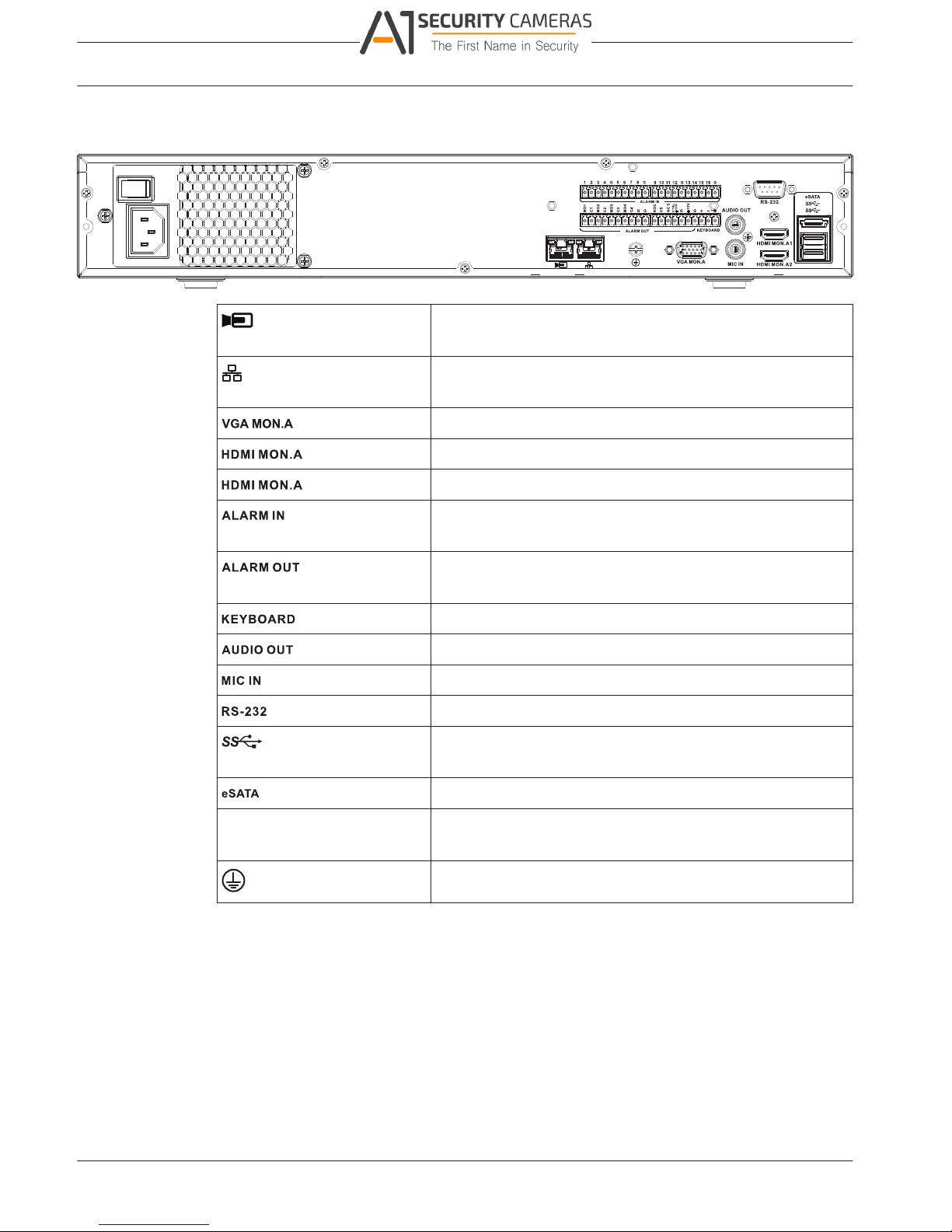
Back panel connectors DIVAR network 5000 (no PoE)
RJ45 video input for max. 32 IP cameras connected via
external switch (optional with DHCP configuration)
RJ45 Ethernet connection (10/100/1000Base-T according to
IEEE802.3)
1 D-SUB (Monitor output)
1 1 HDMI (Monitor output in maximum 4k resolution)
2 1 HDMI (output for spot monitor)
16 screw terminal inputs, cable diameter AWG26‑16 (0.13–
1.5 mm)
6 screw terminal outputs, cable diameter AWG26‑16 (1.29–
0.4 mm)
Screw terminals, cable diameter AWG26‑16 (0.13–1.5 mm)
1 RCA (Audio output)
1 RCA (Audio input)
DB9 male, 9-pin D-type (for service)
Two USB (3.0) connectors for mouse or USB memory device;
one USB (2.0) also on front panel
For backup/memory device
Power input with On/Off
switch
100~240 VAC, 50-60 Hz, 1.9 A, 75 W
Ground connection
2016.09 | v1.0 | AM18-Q0717 Operation Manual Bosch Security Systems
Available from A1 Security Cameras
www.a1securitycameras.com email: sales@a1securitycameras.com
4.2.5
DIVAR 2000 / DIVAR 3000 / DIVAR
Installation | en 17
5000
Back panel connectors DIVAR network 5000 (16 PoE)
PoE
16 RJ45 ports (200 W; max. 25.5 W per port) for connecting
max. 16 PoE cameras connected with DHCP configuration
(max. 32 IP cameras)
RJ45 Ethernet connection (10/100/1000Base-T according to
IEEE802.3)
1 D-SUB (Monitor output)
1 1 HDMI (Monitor output in maximum 4k resolution)
2 1 HDMI (output for spot monitor)
16 screw terminal inputs, cable diameter AWG26‑16 (1.29–
0.4 mm)m)
6 screw terminal outputs, cable diameter AWG26‑16 (1.29–
0.4 mm)
Screw terminals, cable diameter AWG26‑16 (1.29–0.4 mm)
1 RCA (Audio output)
1 RCA (Audio input)
DB9 male, 9-pin D-type
Two USB (3.0) connectors for mouse or USB memory device;
one USB (2.0) also on front panel
For backup/memory device
Power input with On/Off
switch
100~240 VAC, 50-60 Hz, 5 A, 350 W
Ground connection
Bosch Security Systems Operation Manual 2016.09 | v1.0 | AM18-Q0717
Available from A1 Security Cameras
www.a1securitycameras.com email: sales@a1securitycameras.com
4.2.6
DIVAR 2000 / DIVAR 3000 / DIVAR
18 en | Installation
5000
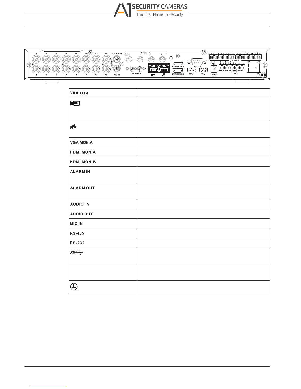
Back panel connectors DIVAR hybrid 3000
16 BNC for connecting max. 16 analog cameras
Max. 16 IP cameras connected via external switch (if no
analog cameras are connected, an extra 16 IP cameras can
be connected)
RJ45 Ethernet connection (10/100/1000Base-T according to
IEEE802.3)
1 D-SUB (Monitor output)
1 HDMI (Monitor output)
1 HDMI (output for spot monitor)
16 screw terminal inputs, cable diameter AWG26‑16 (1.29–
0.4 mm)
4 screw terminal outputs, cable diameter AWG26‑16 (1.29–
0.4 mm)
4 RCA (Audio inputs)
1 RCA (Audio output)
1 RCA (Audio input)
Screw terminal output (Dome control)
DB9 male, 9-pin D-type (Dome control)
One front (2.0) and two rear (3.0) USB connectors for mouse
or USB memory device
Power input with On/Off 12 VDC (5 A)
switch AC input adapter: 100~240 VAC, 50-60 Hz, 1.5 A
Ground connection
2016.09 | v1.0 | AM18-Q0717 Operation Manual Bosch Security Systems
Available from A1 Security Cameras
www.a1securitycameras.com email: sales@a1securitycameras.com
4.2.7
DIVAR 2000 / DIVAR 3000 / DIVAR
Installation | en 19
5000
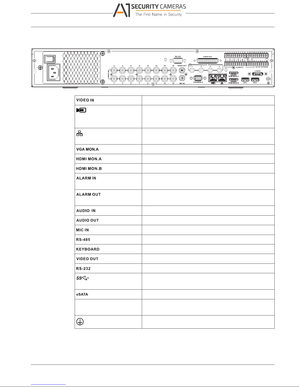
Back panel connectors DIVAR hybrid 5000
16 BNC for connecting max. 16 analog cameras
Max. 16 IP cameras connected with external switch (if no
analog cameras are connected, an extra 16 IP cameras can
be connected)
RJ45 Ethernet connection (10/100/1000Base-T according to
IEEE802.3)
1 D-SUB (Monitor output)
1 HDMI (Monitor output)
1 HDMI (output for spot monitor)
16 screw terminal inputs, cable diameter AWG26‑16 (1.29–
0.4 mm)
4 screw terminal outputs, cable diameter AWG26‑16 (1.29–
0.4 mm)
4 RCA (Audio inputs)
1 RCA (Audio output)
1 RCA (Audio input)
Screw terminal output (Dome control)
Screw terminal output (Keyboard)
D-sub (loop through to other devices)
DB9 male, 9-pin D-type (Dome control)
Two USB (3.0) connectors for mouse or USB memory device;
one USB (2.0) also on front panel
For backup/memory device
Power input with On/Off
switch
100~240 VAC, 50-60 Hz, 1.9 A, 75 W
Ground connection
Browser setup
Use a computer with an internet browser to receive live images, control the unit, and replay
stored sequences. The unit can also be configured over the network using the browser.
Bosch Security Systems Operation Manual 2016.09 | v1.0 | AM18-Q0717
Available from A1 Security Cameras
www.a1securitycameras.com email: sales@a1securitycameras.com
4.2.8

DIVAR 2000 / DIVAR 3000 / DIVAR
20 en | Installation
5000
4.3 Powering up
For units with an external power adapter
1. Switch on all equipment connected to unit.
2. Connect the DC power cord of the power adaptor to the 12 VDC connector on the unit.
3. Connect the AC power cord to the power adaptor.
4. Connect the power adaptor to an AC power outlet.
5. Turn on the unit power ON/OFF switch on the rear of the unit.
For units with 230 VAC input
1. Switch on all equipment connected to unit.
2. Connect the power cable to the unit.
3. Connect the power cable to the AC power outlet.
4. Turn on the unit power ON/OFF switch on the rear of the unit.
4.4 Startup wizard
The Startup Wizard opens automatically when you start your system for the first time. The
wizard will guide you through five setup screens (use the buttons <Default>, <Cancel>,
<Previous>, <Next> to enter values and navigate through the screens):
1. Screen 1
Select your language.
Click <Next>.
2. Screen 2
Assign a User name and password.
Optionally, assign a security question and answer (useful if you forget your password).
Click <Next>.
3. Screen 3
Enter the system time and date.
If required, assign the daylight saving time (DST) fields.
Click <Next>.
4. Screen 4
Leave DHCP selected as default to automatically assign the external network details for
the recorder (or) de-select DHCP and assign network details manually.
Optionally scan the QR code to download the mobile app.
Click <Next>.
5. Screen 5
Click <Search> to search for any connected IP cameras (analog cameras connected to
hybrid recorders and IP cameras connected to PoE ports will be automatically assigned).
Select the required cameras in the Search list and add by clicking <Add> (or double click
a camera). Selected cameras appear in the Device list (if required, Edit or Delete any
connected cameras in the Device list).
Click <Finished>.
6. Confirm the setup by clicking <Save>.
Notice!
Use <Cancel> to automatically install all factory defaults and exit the Startup wizard.
2016.09 | v1.0 | AM18-Q0717 Operation Manual Bosch Security Systems
Available from A1 Security Cameras
www.a1securitycameras.com email: sales@a1securitycameras.com

DIVAR 2000 / DIVAR 3000 / DIVAR
Installation | en 21
5000
4.5
4.6
Login
Log in to your recorder by entering your user name and password, then click <OK>.
Use the supplied USB mouse, front panel, remote control or keyboard to input data and
commands.
Logout/Shutdown
Quick logout
Right-click the mouse to access the Quick menu; and choose the option Logout user.
Shutdown/Logout via Main menu
1. Right-click the mouse to access the Quick menu; from here choose the option Main
menu.
2. Select the Shutdown option on the Main menu.
3. Use the menu to choose from the following options:
Shutdown
Logout (logout user)
Restart (Restart system)
4. Click <OK> to confirm the selection.
Shut down with power button
Another way to shut down the system is to press the power button on the front panel for at
least 3 seconds (the system will automatically backup video recordings and settings).
Start up the system again (and access login screen) by briefly pressing the power button.
Bosch Security Systems Operation Manual 2016.09 | v1.0 | AM18-Q0717
Available from A1 Security Cameras
www.a1securitycameras.com email: sales@a1securitycameras.com

DIVAR 2000 / DIVAR 3000 / DIVAR
22 en | Hardware setup
5000
5 Hardware setup
This chapter contains detailed information about the hardware installation and connection of
external equipment to the unit. The connector types and their pin signals are described. Most
of the connectors are located at the rear panel of the unit. For convenience, one USB port is
located on the front of the unit to connect a mouse or memory device.
All the input/output ports are Safety Extra Low Voltage (SELV) circuits. SELV circuits should
only be connected to other SELV circuits.
5.1 Keyboard connection (only DIVAR 5000 models)
Use the keyboard connection on the back of the unit to connect a Bosch Intuikey keyboard
using one of the following methods:
– use the supplied RJ11 adaptor – see Connect using RJ11 adapter
– strip the keyboard cable (or equivalent cable) to connect leads directly – see Connect
wires directly
For short distances (up to 30 m), standard 6-core telecom flat cable can be used to supply
signal connections for the keyboard (LTC 8558/00). Always use the Keyboard Extension Kit
(LTC 8557) for distances over 30 m between the keyboard and the DVR; this kit provides
junction boxes and cables. Maximum cable length: 30 m (using standard 6-core telecom flat
cable), or 1.5 km (using Belden 8760 or equivalent).
The appropriate power supply (11 - 12.6 VDC, maximum 400 mA) to externally power the
keyboard must be purchased separately.
5.1.1 Connect using RJ11 adapter
Connect the adapter as follows:
– red cable to the (-) of the keyboard control connector
– green cable connects to the (+) of the keyboard control connector
– white cable to ground
– blue cable to +12V
2016.09 | v1.0 | AM18-Q0717 Operation Manual Bosch Security Systems
Available from A1 Security Cameras
www.a1securitycameras.com email: sales@a1securitycameras.com
5.1.2
DIVAR 2000 / DIVAR 3000 / DIVAR
Hardware setup | en 23
5000
RS-485 KEYBOARD
power to
keyboard
keyboard
control
G
+
_
G
G
+
_
G
+12V
CTRL
+12V
DVR
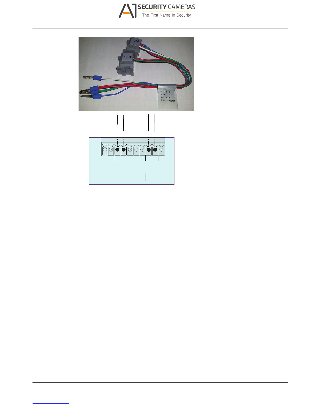
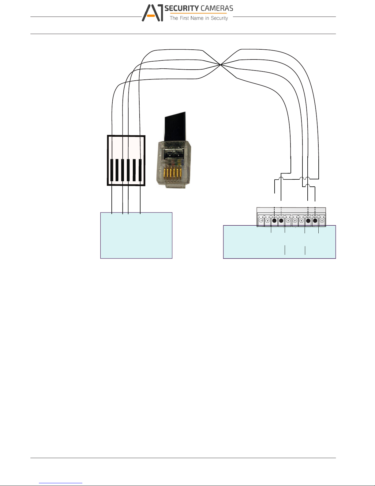
Connect wires directly
1. Cut off one of the connectors at the end of the cable.
2. Strip cable wires 1, 3, 4 and 6.
3. Attach the stripped wires to the keyboard connector on the back of the DVR according to
the following figure.
4. Insert the attached cable connector into the DVR connector on the back of the keyboard.
Bosch Security Systems Operation Manual 2016.09 | v1.0 | AM18-Q0717
Available from A1 Security Cameras
www.a1securitycameras.com email: sales@a1securitycameras.com
5.2
DIVAR 2000 / DIVAR 3000 / DIVAR
24 en | Hardware setup
5000
RS-485 KEYBOARD
power to
keyboard
keyboard
control
+12V
Keyboard RJ11 cable (or equivalent)
G
G
+
_
G
G
+
_
G
+12V
CTRL
+12V
_
+
DIVAR 5000
KEYBOARD
+12V
+
_
G
+12V
G
G
+12V
_
+
+
_
RS485 port connection (only hybrid models)
Use the RS485 connector to connect Bosch, Pelco-P or Pelco-D controllable cameras to the
unit for pan, tilt, and zoom control. RS485 is a single-direction protocol; the PTZ device can’t
return any data to the unit.
Since RS485 is disabled by default for each camera, you must enable the PTZ settings as
follows:
1. Connect a suitable cable to the RS485 connection on the DVR rear panel.
2. Connect the other end of the cable to the appropriate pins in the camera connector.
3. Follow the instructions in the Operation section of this manual to configure the camera
for PTZ control.
The Bosch protocol is supported with the following baud settings:
– 9600 baud
– 8 data bits
– 1 stop bit
– no parity
– no flow control
2016.09 | v1.0 | AM18-Q0717 Operation Manual Bosch Security Systems
Available from A1 Security Cameras
www.a1securitycameras.com email: sales@a1securitycameras.com
5.3
DIVAR 2000 / DIVAR 3000 / DIVAR
Hardware setup | en 25
5000
Figure 5.1: RS485 connector
Signal name Pin number Description
TX + 1 Data transmission
TX - 2 Data transmission
GND 3 Shield
Max. signal voltage is -8 to +12 V. The recommended cable cross section is AWG 28-16
(0.08-1.5 mm2).
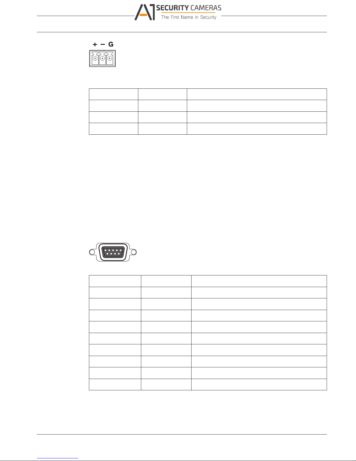
RS232 port connections
The RS232 port can be used to connect different devices:
– Console
– PTZ Matrix - a pan and tilt control unit (using RS232 to Biphase converter)
The device type and required settings can be assigned in the menu (Settings > System >
Serial Port).
Specifications
Connector type: 9-pole D-type male connector
Maximum input voltage: ±25 V
Communication protocol: Output signals according EIA/TIA-232-F
Figure 5.2: RS232 serial port
Signal name Pin number Description
DCD_in 1 Carrier detection signal (not used)
RX 2 RS232 receive signal
TX 3 RS232 transmit signal
N/C 4 No connection
System ground 5 System ground
N/C 6 No connection
RTS 7 RS232 request to send signal
CTS 8 RS232 clear to send signal
N/C 9 No connection
Alarm I/O connections
Alarm inputs and outputs are fitted as screw down terminal blocks on the unit. Cable cross
section is AWG 26-16 (1.29 to 0.4 mm
2
).
Bosch Security Systems Operation Manual 2016.09 | v1.0 | AM18-Q0717
Available from A1 Security Cameras
www.a1securitycameras.com email: sales@a1securitycameras.com
5.4

DIVAR 2000 / DIVAR 3000 / DIVAR
26 en | Hardware setup
5000
DIVAR 2000/3000
1, 2, 3, 4 Alarm inputs: max. 4. The alarm becomes active at low voltage. Max.
input voltage 15 VDC.
NO1 C1, Two groups of normal open activation outputs (on/off button).
NO2 C2,
G Ground cable.
DIVAR 5000
1, 2, 3, 4, 5,
6, 7, 8, 9, 10,
11, 12, 13, 14,
15, 16
Alarm inputs: max. 16. The alarm becomes active at low voltage.
NO1 C1,
NO2 C2,
NO3 C3,
NO4 C4,
NO5 C5
Groups of normal open activation alarm outputs (on/off button).
CTRL +12V Control power output. Always close the device power to cancel the
alarm.
+12V External power output. Need the peripheral equipment to provide
+12 V power (below 500 mA).
G Ground cable.
2016.09 | v1.0 | AM18-Q0717 Operation Manual Bosch Security Systems
Available from A1 Security Cameras
www.a1securitycameras.com email: sales@a1securitycameras.com
 Loading...