

Page 1

P 4M 890-M7 P C I- E Se t up Manu a l
FCC Information and Copyright
This equipment has been tested and found to comply with the limits of a Class
B digital device, pursuant to Part 15 of the FCC Rules. These limits are designed
to p rovid e reasonab le protec tion agains t harmful interfe rence in a residential
installation. This equipment generates, uses and can radiate radio frequency
energy and, if not installed and used in accordance with the instructions , may
cause harmful interference to radio communications. There is no guarantee
that interfe rence will not oc cur in a pa rticular ins ta llation .
The vendo r makes no represe ntations o r warra nties with res pec t t o t he
contents here and specially disclaims any implied warranties of merchantability
o r fi tness fo r any purpos e . F u rt he r the vendor res e rves t he ri g ht to r evis e th is
publication and to make changes to the c ontents here without obligation to
notify any party beforehand.
D uplica tion of this publ ication , in part or in whole, is not allo wed without first
obtaining the vendor’s approval in writing.
The content of this user’s manual is subject to be changed without notice and
we will not be responsible for any mis takes found in this user’s manual. All the
brand and product names are trademarks of their respective companies.
Page 2

Table of Contents
Chapt er 1: INTRODUCTION........................................3
1.1 BEFOR E YOU STAR T.............................................................3
1.2 P ACK A GE CHECKLIST...........................................................3
1.3 MOTHERBO ARD FEATU RES .................................................. 4
1.4 REA R PANEL CONNE CTORS .................................................5
1.5 Mo t he r bo ar d Layou t............................................................ 6
Chapt er 2: Hardware Installation..............................7
2.1 Installing Central Processing Unit (CPU)................................ 7
2.2 FAN Headers........................................................................9
2.3 Installing System Memory.....................................................10
2.4 Con nectors and Slo ts............................................................11
Chapter 3: Headers & Jumpers Setup......................13
3.1 How to Se t up Ju mpers..........................................................13
3.2 Det ail Settin gs.....................................................................13
Chapter 4: USEFUL HELP...........................................19
4.1 DRIVE R INSTA LLATION NOTE..............................................19
4.2 AWARD BIOS B EEP CODE....................................................20
4.3 EXTRA INF O RMATION.........................................................20
4.4 TROUBLESHOOTING...........................................................22
Chapt er 5: WarpSpeeder™ .......................................23
5.1 Introduction........................................................................23
5.2 System Requirement............................................................23
5.3 Installation.........................................................................24
5.4 WarpSpeeder™....................................................................25
Appendencies: SPEC In Other Language ................32
German................................................................................................32
France..................................................................................................34
Italian..................................................................................................36
Spanish ................................................................................................38
Portuguese ...........................................................................................40
Polish...................................................................................................42
RUSSIAN...............................................................................................44
ARABIC................................................................................................46
JAPANESE............................................................................................48
Page 3

P4M890-M7 PCI-E
CHAPTER 1: INTRODUCTION
1.1 BEFORE YOU START
Tha nk you for choosing our product. Before you sta rt ins talling the
mothe rboa rd, plea se m ake sure you follo w the i ns tru ctions be lo w:
Prepare a dry and stable working environment with
s ufficie nt li gh ting .
Always disconnect the computer from power outlet
be fo re ope ration .
Befo re you take the m o the rboa rd ou t f rom a n ti -s ta tic
bag, ground yourself properly by touching any safely
grounde d appliance, or use gro unded wrist s trap to
remove the static charge.
Avo id touch ing the compone nts o n mo the rboa rd o r the
rea r side of the board unless necessa ry. Hold the bo ard
on the edge , do not try to bend or flex the boa rd.
Do no t leave any unfastened small parts inside the
case after installation. Loose parts will cause short
circuits which ma y damage the equipment.
Keep the computer from dangerous area, such as heat
source , humid a ir and water.
1.2 PACKAGE CHECKL IST
z HDD Cable X 1
z Use r’s Manual X 1
z Fully Setup Driver CD X 1
z Rear I/O Panel for ATX Case X 1
z FDD Cable X 1 (optional)
z Se ria l ATA Cab le X 1 ( op tiona l)
z USB 2.0 Cable X1 (optional)
z S/PDIF Cable X 1 (optional)
z Se ria l ATA Po we r Cab le X 1 (o pt io na l)
3
Page 4
Motherboard Manual
/
/
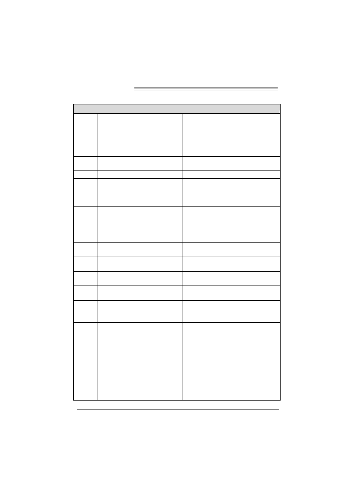
1.3 MOTHERBOARD FEATURES
SPEC
LGA 77 5
Intel Core 2Duo
CPU
FS B 533 / 800 / 106 6 MHz
Chipset
Graphic Integrat ed in UniChrome Pro Chipset Max Shared Video Memory is 6 4 MB
Super I/O
Main
Memory
IDE Integrated IDE Controller
SATA Integrated Seri al ATA Controller
LAN PHY Realtek RTL 8201CL
Sound
Codec
On Board
Connector
Celeron D pr ocessor up to 3.8 GHz
*It is recommende d to use processors
with 95W power consum pti on.
VIA P4M890
VIA VT8237R+
ITE I T 8712F
Provides the most commonly used
legacy Super I/O fu nctionality.
Low Pin C ount Interf ace
DIMM Slots x 2
Supports D DR2 400 / 533
Each DIMM supports
256/512MB /1GB/2GB DDR2
Max Memory C apicity 4GB
AL C655 / 658
PCI Express x 16 slot x1 Supports PCI express x16 expansion cards
PCI Express x 1 slot x1 Supports PCI express x1 expansion cards Slots
PCI slot x2 Supports PCI expansion cards
Floppy connector x1 Each connector supports 2 Floppy drives
IDE Connector x2 Each connector supports 2 IDE device
SATA Connector x2 Each connector supports 1 SATA devices
Front Pa nel Connector x1 Supports front panel facilities
Front Audi o Co nnector x1 Supports front panel audio func tion
CD-in Co nnector x1 Supports C D audio-i n func tion
S/PDIF o ut co nnector x1 Supports di git al a udio out function
CPU Fan header x1
System Fan header x1 System Fan Power su pply
Cl ear CMOS head er x1 Res tore C MO S data t o fact ory default
Pe ntium 4 / Pe ntium D
Suppor ts Hy per Tra ns port / Exec ute Di sabl e
Bit / Enhanced Intel SpeedStep®/ Intel
Extended Memory 64 technology
Environment Control initiatives,
H/W Monitor
Fan S pee d Co ntroller
ITE' s "Sm art Guardian" func tion
Single Channel Mode DDR2 memory module
Registered DIMM and Non-ECC DIMM is not
supported
Ultra DMA 33~133 B us Master Mode
supports PIO Mode 0~4,
Data transfer rates up to 1.5 Gb/s.
SATA Version 1.0 specification complia nt.
10 / 100 Mb/s auto negotiation
Half / Full duplex capability
6 channels audio out
AC ’97 V ersion 2.3
CPU Fan power s upply (wi th S mar t Fan
function)
4
Page 5
P4M890-M7 PCI-E
SPEC
USB connector x2
Power Connector (24pin) x1 Connects to Power supply
Power Connector (4pin) x1 Connects to Power supply
PS/2 Keyb oard x1
PS/2 Mo use x1
Serial Port x1
Back Panel
I/O
Board S iz e 190 mm (W) x 244 m m (L) Mi cr o ATX form Fact or
OS
Suppor t
Printer Port x1
VGA Port x1
LAN port x1
USB Port x4
Audio Jack x3
Windows 2000 / XP
Each connector supports 2 fr ont panel USB
port s
Connects to PS/2 Keyboard
Connect s to PS / 2 Mo use
Provide RS-232 S eri al connect ion
Connects to various types of device
Connect s to monitor.
Connects to RJ-45 ethernet cable
Connects to USB devices
Provide A udio-I n/Out and microp ho ne
connection
Biostar Reserves the right to add or r emove
support for any OS with or without notice.
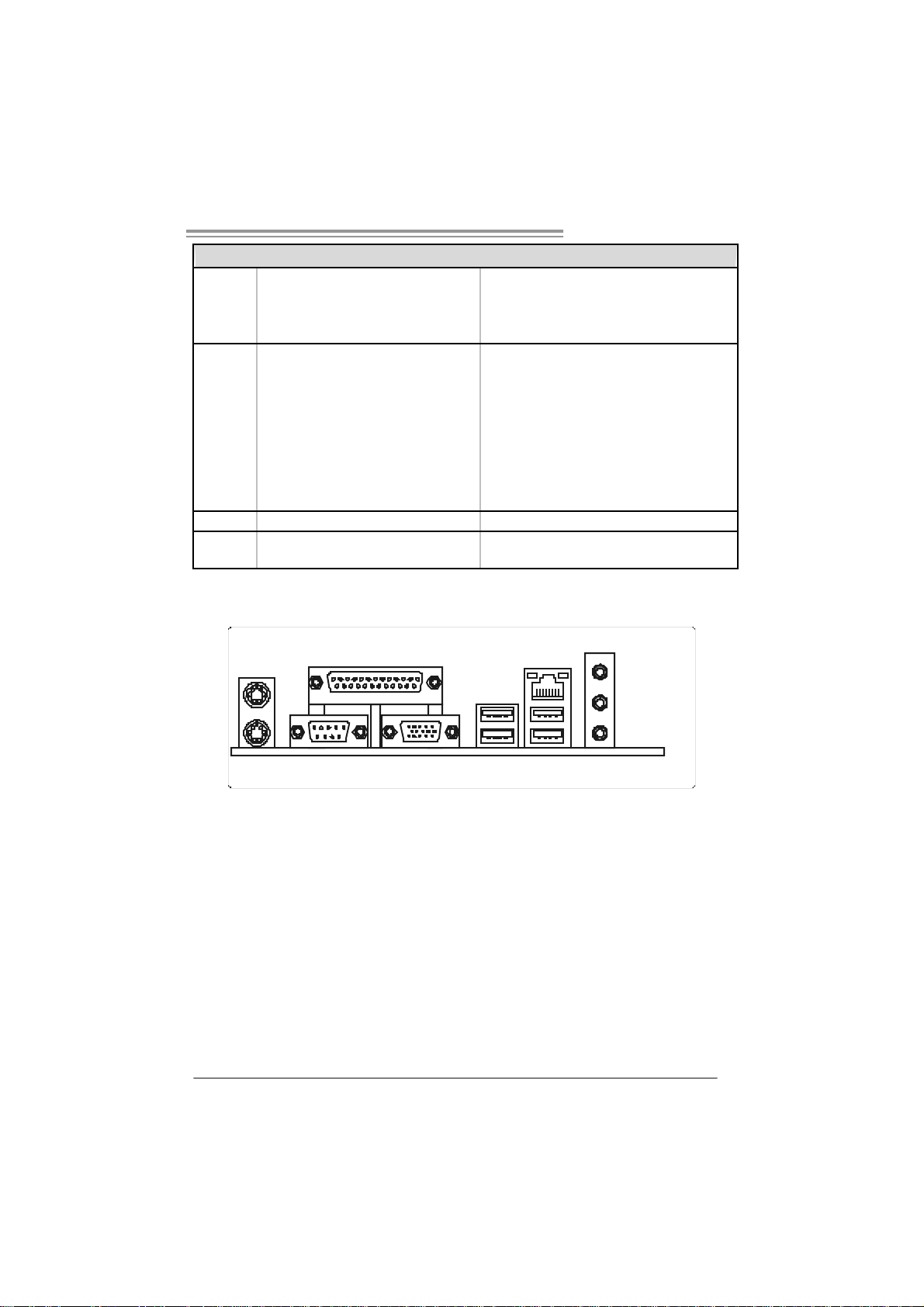
1.4 REA R PANEL CONNECTORS
PS/2
Mou se
Pr inte r Port
LAN
Line In/
Sur round
Line Out
Mic In 1 /
Bass/ Cente r
PS/2
Keyboa rd
COM1 VGA1 USBX2USBX2
5
Page 6
Motherboard Manual
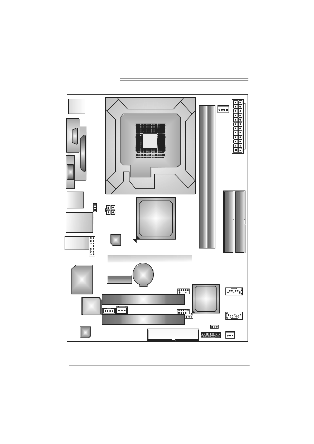
1.5 MOTHERBOARD LAYOUT
JKBMS1
C
O
J
M
C
1
O
M
1
JPRNT1
JVGA1
JUSB2
JRJ45USB1
JAUDIO1
JUSBV1
JATXPWR2
LAN
LGA775
CPU1
P4M890
JCFAN1
JAT XPWR1
DDR 2_B1
DDR2_A1
IDE1
IDE2
6
JAUDIO2
Super
I/O
BIOS
Codec
Note: represents the 1■
JCDIN1
PCI-EX1_1
PCI-EX16
BAT1
PCI1
JSPDIF_ OUT1
PCI2
st
pin.
JUSB2
JUSB3
FDD1
JUSBV2
VIA
VT8237R+
JC MO S1
JPANEL1
JSATA2
JSATA1
JSF AN1
Page 7
P4M890-M7 PCI-E
CHAPTER 2: HARDWARE INSTALLATION
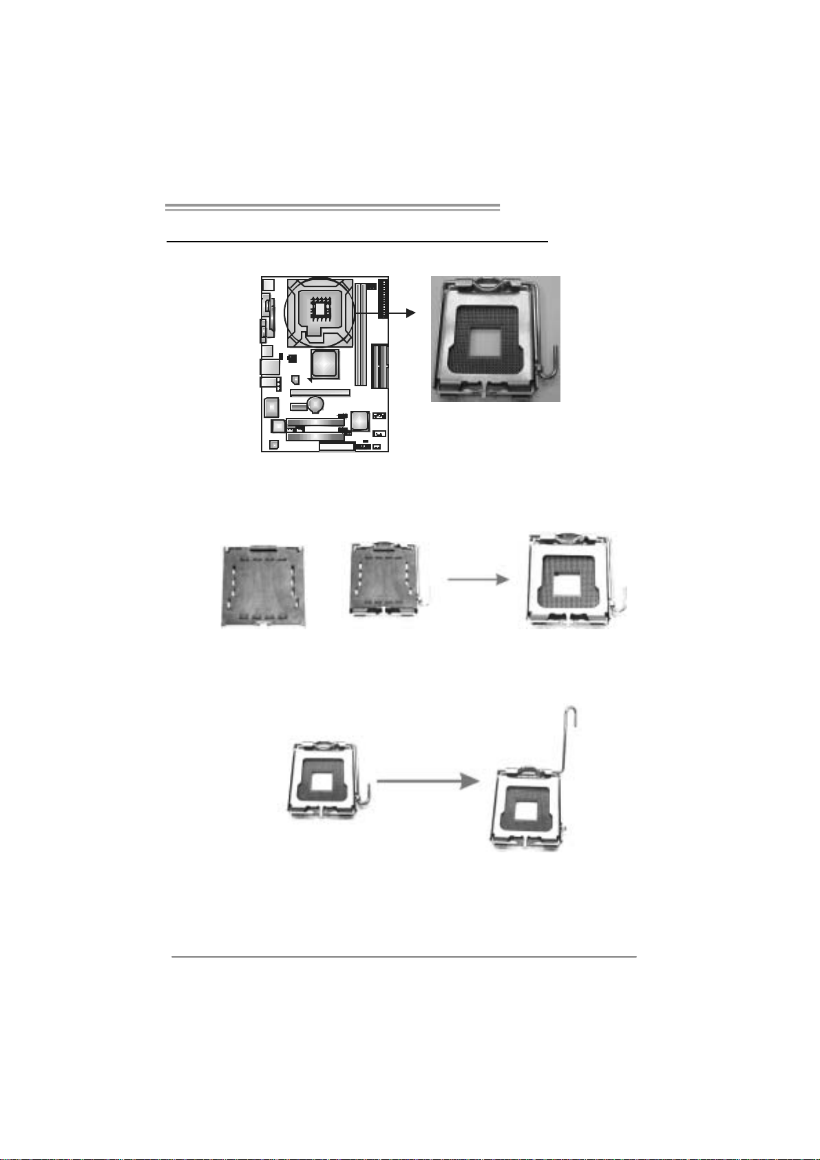
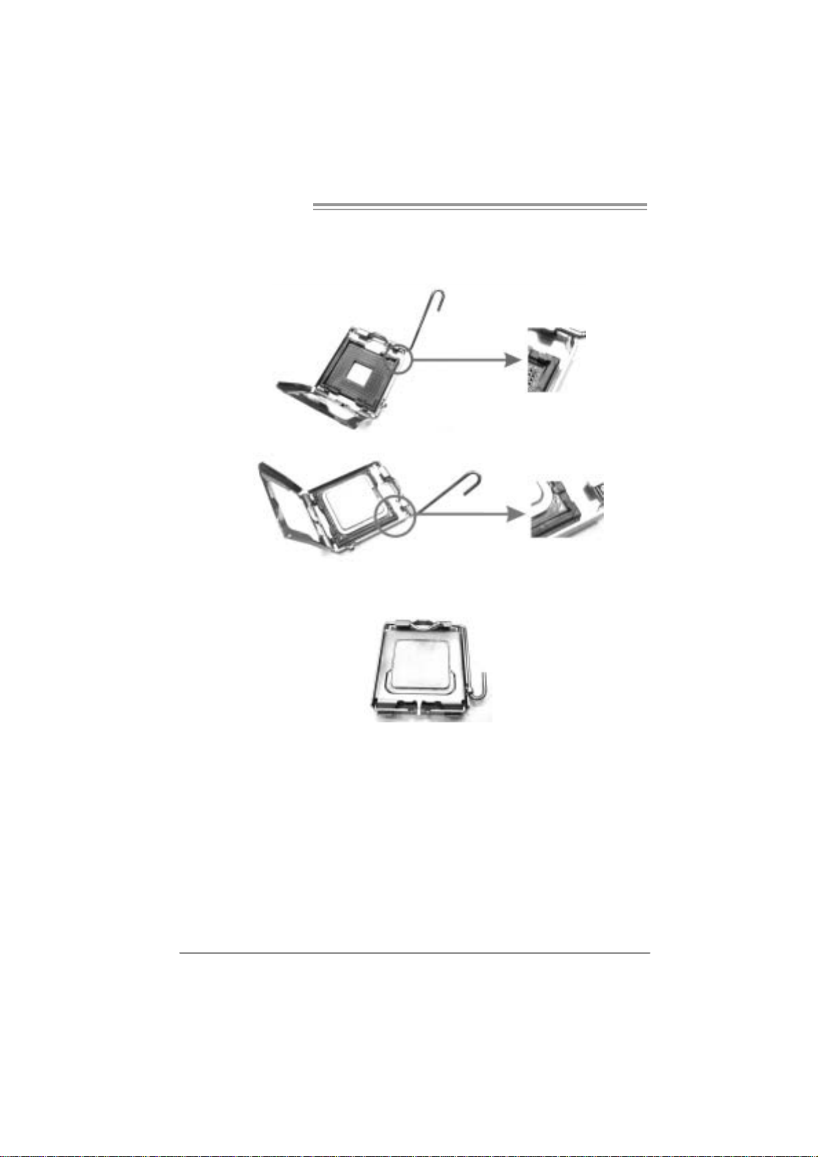
2.1 INSTALLING CENTRAL PROCESSING UNIT (CPU)
Special Notice:
Remo v e Pin Cap before installation, and m ake goo d preservation
for future use. When the CPU is removed, cover the Pin Cap on the
empty so cket to ensure pin legs won’ t be damag ed.
Pin Cap
Step 1: Pull the socket locking lever out from the socket and then raise
the lever up to a 90-degree angle.
7
Page 8
Motherboard Manual
Step 2: Look for the triangular cut edge on socket, and the golden dot on
CPU should point forwards this triangular cut edge. The CPU will
fit only in the correct orientation.
Step 2-1:
Step 2-2:
Step 3: Hold th e CPU down firmly, and then lower the lever to locked
position to complete the installation.
Step 4: Put the CPU Fan and heatsink assembly on the CPU and buckle it
on the retention frame. Connect the CPU FAN power cable into
the JCFAN1. This completes the installation.
8
Page 9
P4M890-M7 PCI-E
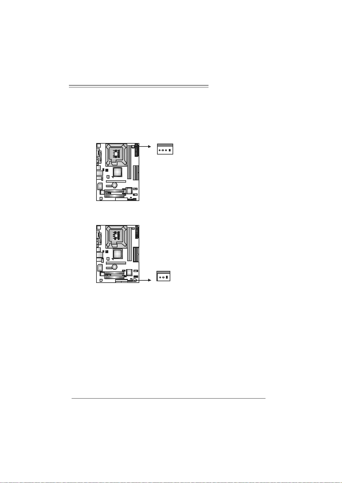
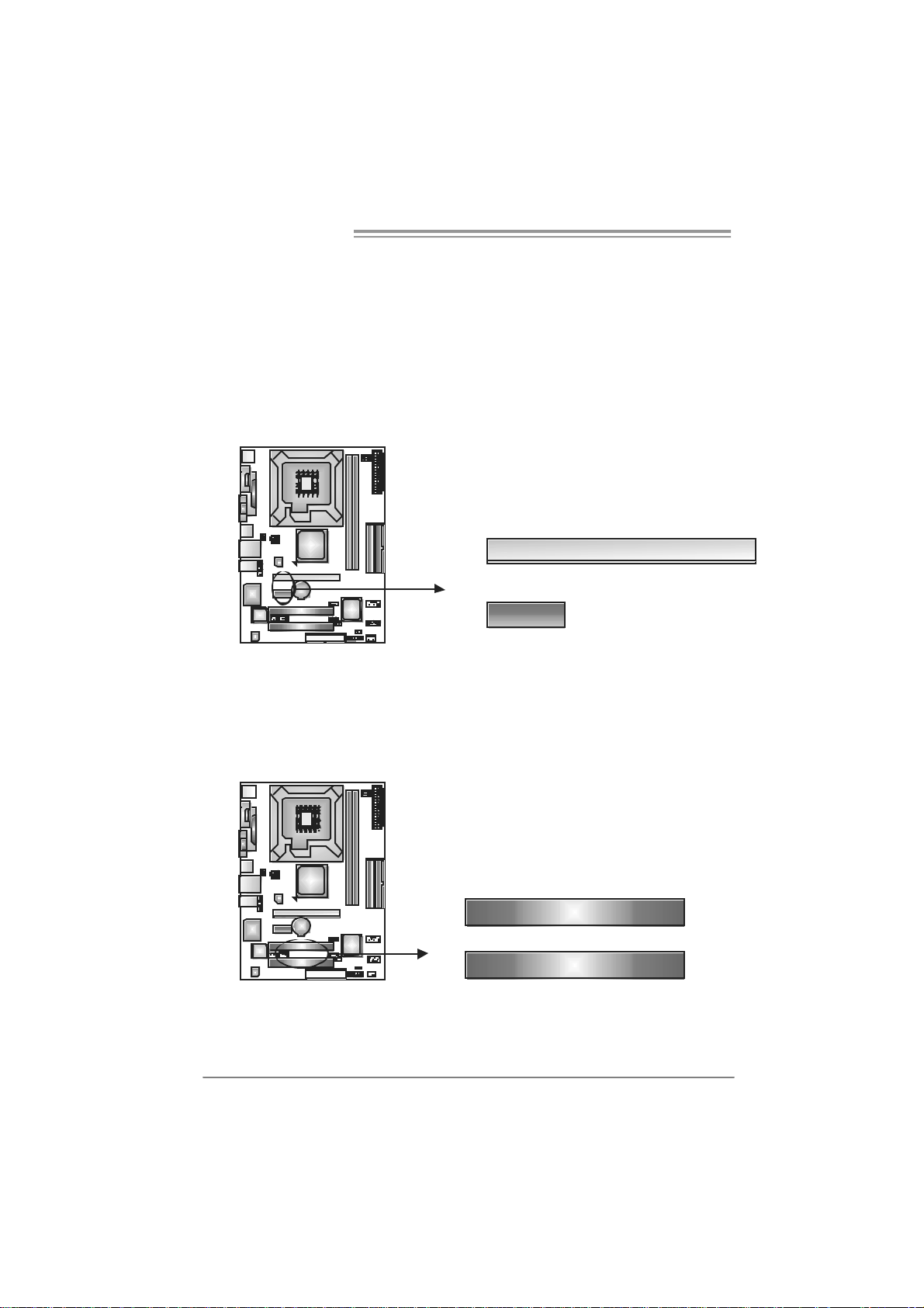
2.2 FAN HEADERS
These fan headers support cooling-fans built in the computer. The fan
cable and connector may be different according to the fan manufacturer.
Connect the fan cable to the connector while matching the black wire to
pin#1.
JCFAN1: CPU Fa n Header
Pin
Assignment
1 Ground
2 +12V
3 FAN RPM rate
sense
4 Smart Fan
Control
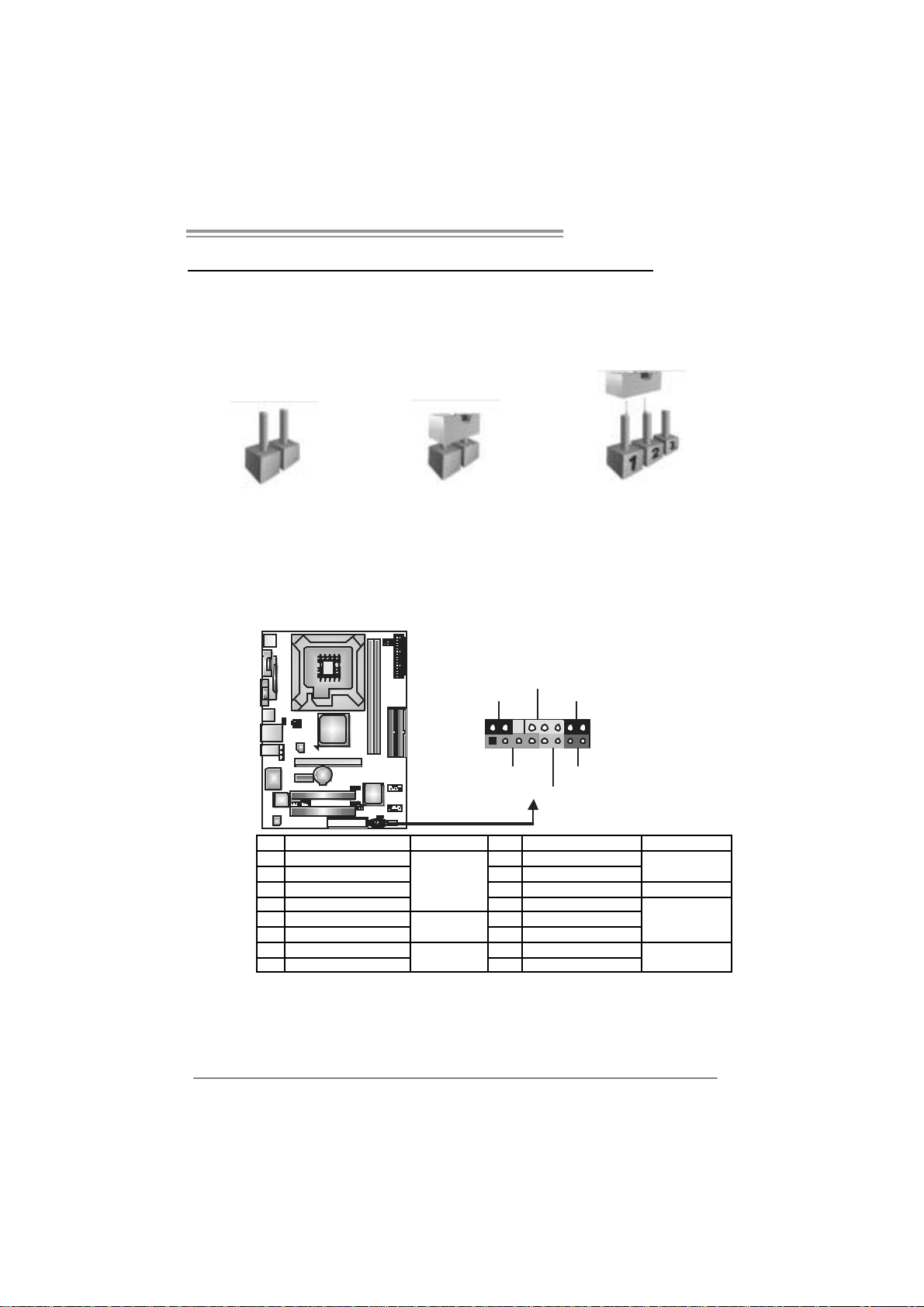
Pin
Assignment
1 Ground
2 +12V
3 FAN RPM rate
sense
JSF AN1 : Sy stem F an H eader
Note:
The JSFAN1 support 3-pi n head connector. When connecti ng with wires onto connec tors,
please note that the red wire is the positi ve and s hould be connected to pin#2, and the
black wire is Ground and s hould be c onnected to GND.
14
JCF AN1
JSFAN1
13
9
Page 10
Motherboard Manual
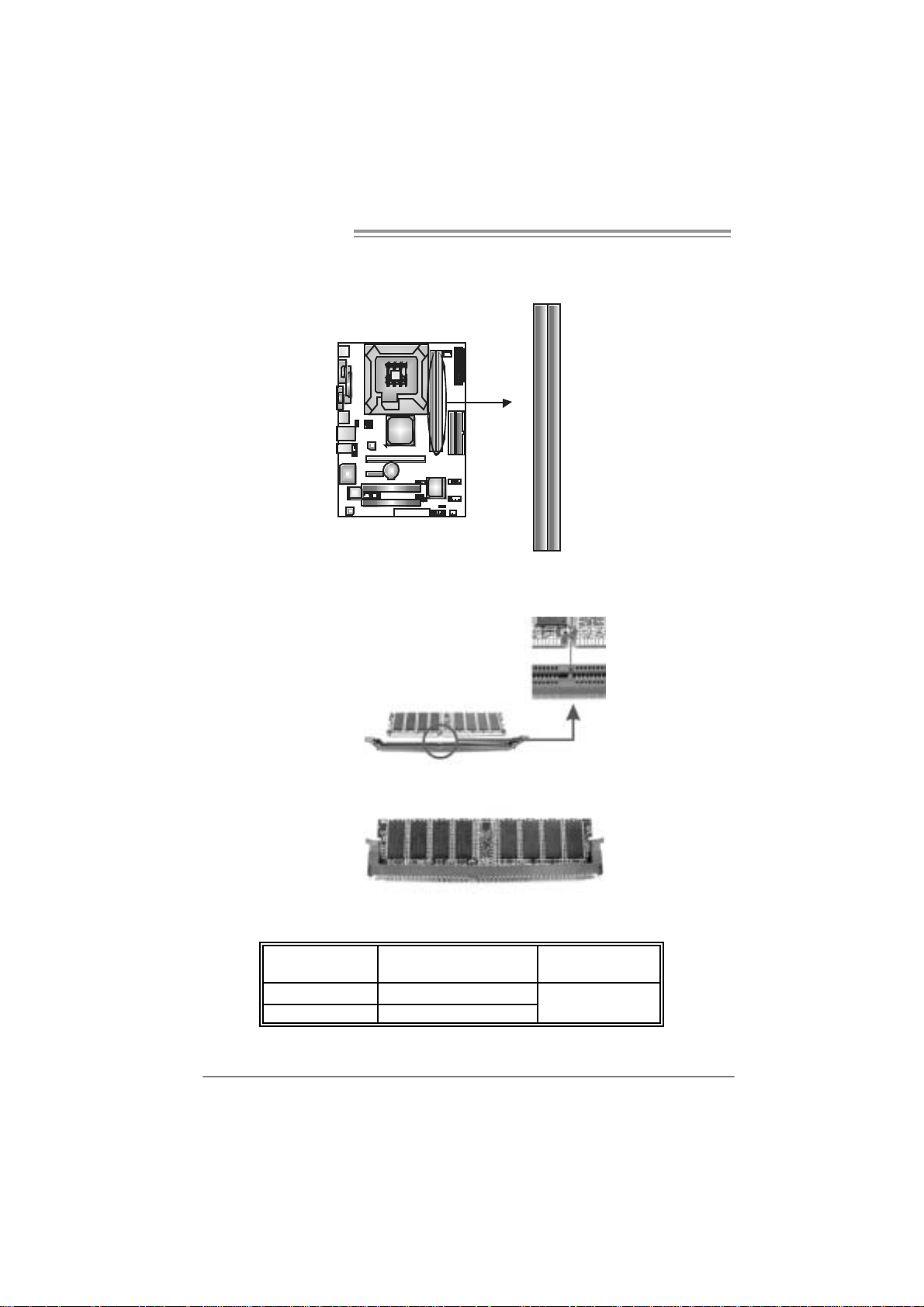
2.3 INSTALLING SYSTEM MEMORY
A. Me mo ry Modu le s
DDR2_B1
DDR2_A1
1. Unlock a DIMM slot by pressing the retaining clips outward. Align a
DIMM on the slot such that the notch on the DIMM matches the
break on the Slot.
2. Insert the DIMM vertically and firmly into the slot until the retaining
chip snap back in place and the DIMM is properly seated.
B. Memory Capacity
DIMM Socket
Location
DDR2 A1 256MB/512MB/1GB/2GB
DDR2 B1 256MB/512MB/1GB/2GB
DDR Module
To t a l Me m o r y
Size
Max i s 4G B.
10
Page 11
P4M890-M7 PCI-E
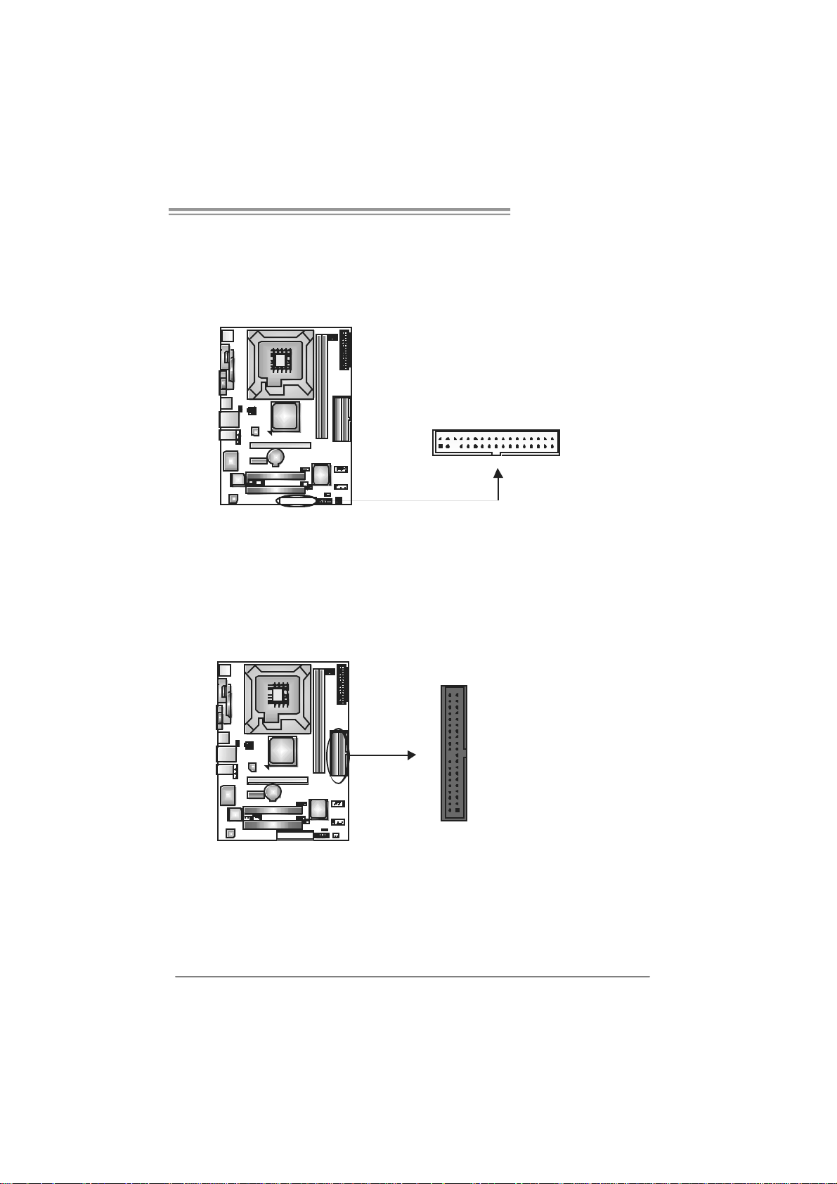
2.4 CONNECTORS AND SLOTS
FDD1: Floppy Disk Conne c tor
The motherboard provides a st andard floppy disk connector t hat supports 360K,
720K, 1. 2M, 1.44M and 2.88M f loppy disk types. This c onnector support s the
provided f loppy drive ribbon c ables.
IDE1/IDE2 : H ard Disk Connecto rs
The motherboard has a 32-bit Enhanced PCI IDE Cont roller that provides PIO
Mode 0~4, Bus Master, and Ultra DMA 33/66/100/133 funct ionality . It has two
HDD connect ors I D E1 (primary ) and ID E2 (secondary).
The IDE connectors can c onnect a master and a slav e drive, so y ou can
connec t up t o four hard disk drives. The f irst hard drive should always be
connec t ed to IDE1.
2
1
3940
21
34
33
IDE2IDE1
11
Page 12
Motherboard Manual
PCI-Ex16: PCI-Express x16 Slot
- PCI -Ex press 1.0a c ompliant.
- Maximum theoretical realized bandwidth of 4GB/s simultaneously per
direct ion, f or an aggregate of 8GB/s tot ally.
PCI-E x1_1: PCI-E xpress x1 slots
- PCI -Ex press 1.0a c ompliant.
- Dat a transfer bandwidth up to 250MB/s per direc t ion; 500MB/s in tot al.
- PCI -Ex press supports a raw bit -rate of 2. 5Gb/s on the dat a pins.
- 2X bandwidth over the t radit ional PCI archit ecture.
PCI-EX16
PCI-EX1_1
PC I1~PCI2: Peripheral Componen t Interconne ct Sl ots
This mot herboard is equipped with 2 standard PCI slots. PCI stands f or
Peripheral Com ponent I nt erconnect, and it is a bus standard f or expans ion
cards . This PCI slot is des ignated as 32 bits .
12
PCI1
PCI2
Page 13
P4M890-M7 PCI-E
CHAPTER 3: HEADERS & JUMPERS SETUP
3.1 HOW TO SET UP JUMPERS
The illustration shows how to set up jumpers. When the jumper cap is
placed on pins, the jumper is “close”, if not, that means the jumper is
“open”.
Pin opened Pin closed Pin1-2 closed
3.2 DETAIL SETTINGS
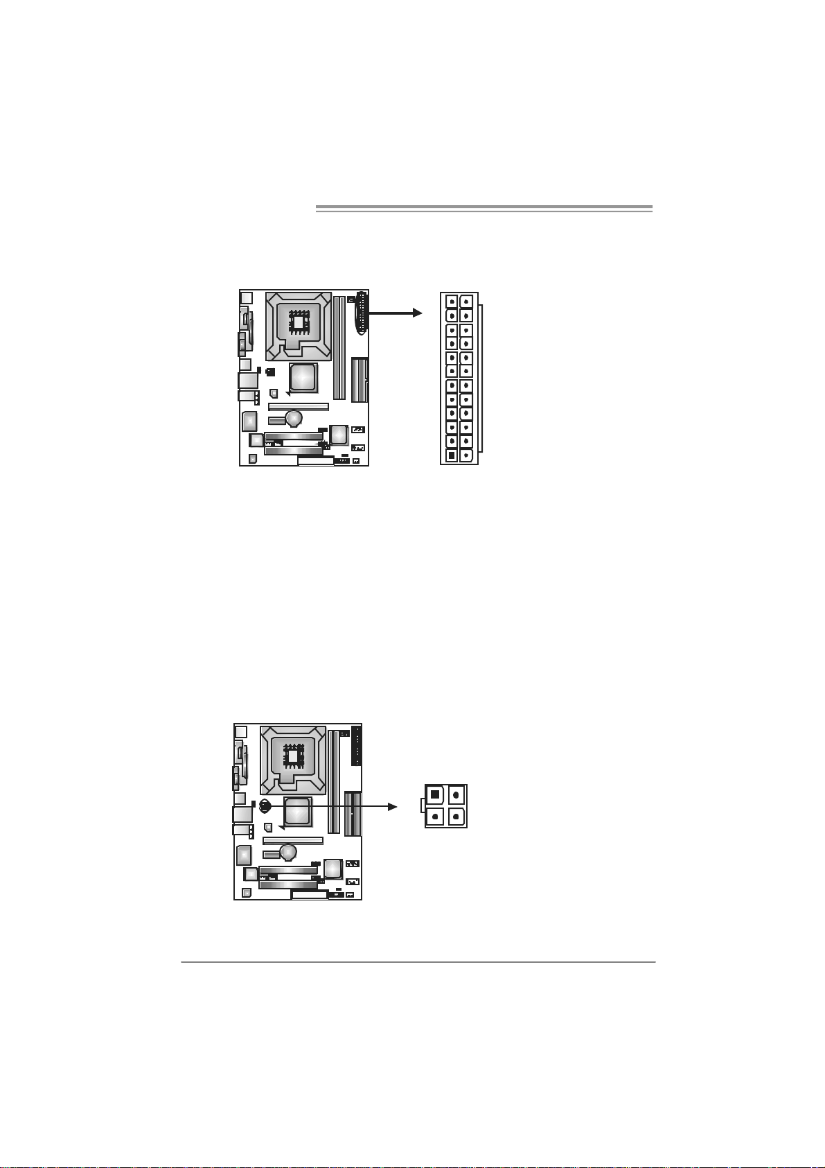
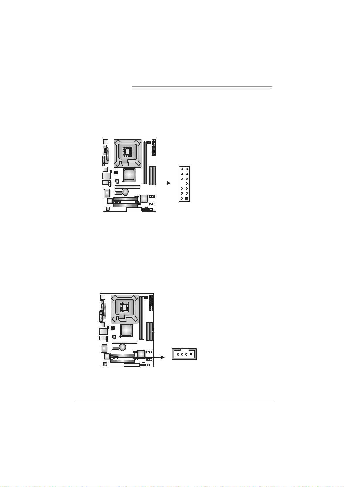
JPANEL1: Front Panel Header
This 16-pin connector includes Power-on, Res et, HDD LED , Power LED, Sleep
butt on and speak er connection. It allows user t o connec t the PC c ase’s front
panel switch f unctions.
PWR_LED
SLP
9
1
SPK
++
HLED
+
On/Off
-
RST
16
8
Pin Assignment Function Pin Assignment Function
1 +5V 9 Sleep control
2 N/A 10 Ground
3 N/A 11 N/A N/A
4 Speaker
5 HDD LED (+) 13 Power LED (+)
6 HDD LED (-)
7 Ground 15 Power button
8 Reset control
Speaker
Connector
Hard drive
LED
Reset button
12 Power LED (+)
14 Power LED (-)
16 Ground
Sleep button
Powe r LED
Power-on button
13
Page 14
Motherboard Manual
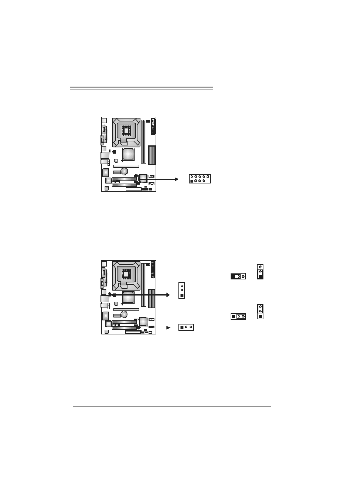
ATX Power Source Connector: JATX PWR1
JATXPWR1 allows us er to c onnect 24-pin power connector on t he ATX power
supply.
12
1
Pin Assignment P in Ass ignment
24
13
13 +3.3V 1 +3.3V
14 -12V 2 +3.3V
15 Ground 3 Ground
16 PS_ON 4 +5V
17 Ground 5 Ground
18 Ground 6 +5V
19 Ground 7 Ground
20 NC 8 PW_OK
21 +5V 9 Standby Voltage+5V
22 +5V 10 +12V
23 +5V 11 +12V
24 Ground 12 +3.3V
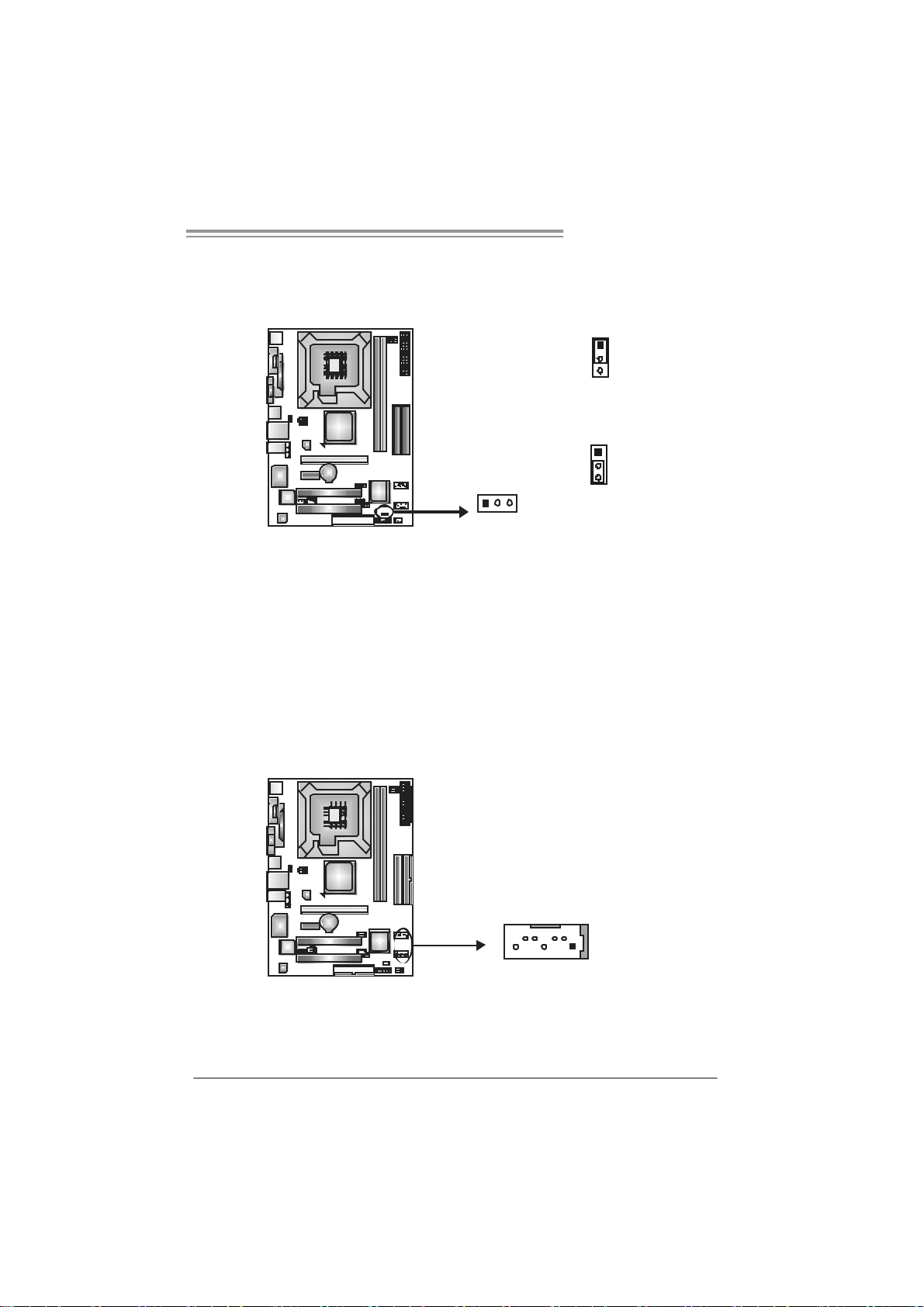
JATXPWR2: ATX Powe r S o u rce Conn e ctor
By c onnecting this connector, it will provide +12V to CPU power c irc uit.
Pin
12
3
4
Assignment
1 +12V
2 +12V
3 Ground
4 Ground
14
Page 15
P4M890-M7 PCI-E
JU S B2/JUS B 3: Head er s for USB 2. 0 P orts at Front Pan el
This header allows us er to c onnect additional U SB cable on t he PC f ront panel,
and also can be c onnected wit h internal U SB devices, like U SB card reader.
Assignment
Pin
1 +5V (fused)
2 +5V (fused)
3 USB4 USB5 USB+
6 USB+
7 Ground
10
9
JUSB2
JUSB3
2
1
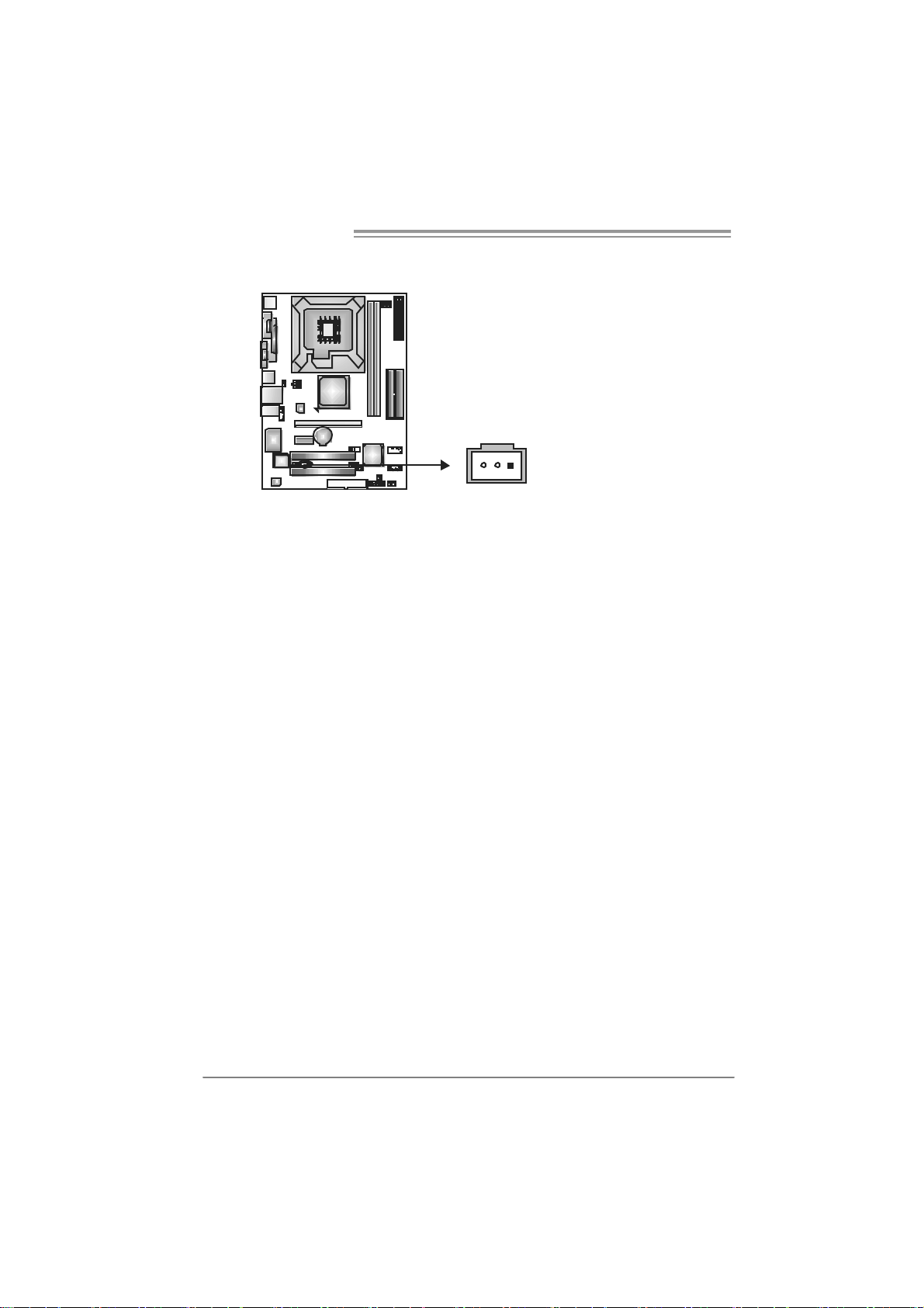
JUS B V1/JUSBV2: Power Sour ce He aders f or USB Ports
Pin 1-2 Close:
JU SBV1: +5V f or USB ports at JUSBLAN 1.
JU SBV2: +5V f or USB ports at f ront panel (JUSB2/JU SB3).
Pin 2-3 Close:
JU SBV1: USB ports at J U SBLAN1 are powered by +5V s t andby v olt age.
JU SBV2: USB ports at f ront panel (J U SB2/JUSB3) are powered by +5V
standby voltage.
8 Ground
9 Key
10 NC
3
31
1
3
1
3
1
JUSBV1
13
JUSBV2
Pin 1-2 close
1
3
Pin 2-3 close
Note:
In order to support this function “Power-On system via USB device,” “JUSBV1/ JUSBV2”
jum per cap should be placed on Pin 2-3 indi vidually.
15
Page 16
Motherboard Manual
JAUDIO2: Fr o n t Pan el Audio He ader
This header allows us er to c onnect the front audio output cable wit h the PC front
panel. It will dis able the out put on back panel audio connectors.
14
Pin Assignment
1 Mic in/center
2 Ground
3 Mic power/Bass
4 Audio power
5 Right line out/
Speaker out Right
6 Right line out/
Speaker out Right
13
12
7 Reserved
8 Key
9 Left line out/
10 Left line out/
11 Right line in/
12 Right line in/
13 Left line in/
14 Left line in/
Speaker out Left
Speaker out Left
Rear speaker Right
Rear speaker Right
Rear speaker Left
Rear speaker Left
JCDIN1: CD-R OM A ud io-in Con nector
This connector allows user t o connect t he audio sourc e from the variaty dev ic es,
like CD-R OM, DVD-ROM, PC I sound card, PCI TV turner c ard etc .
16
Assignment
Pin
1 Left Channel Input
2 Ground
3 Ground
4 Right Channel Input
14
Page 17
P4M890-M7 PCI-E
JCMOS 1 : Clea r CMOS H e a der
By plac ing the jum per on pin2-3, it allows us er to restore the BI OS safe set t ing
and the CMOS data, please caref ully f ollow the procedures to av oid damaging
the m otherboard.
1
3
Pin 1-2 Close:
Normal Operation (default).
1
3
13
※ Clear CMOS Procedures:
1. R em ov e AC power line.
2. Set the jumper to “Pin 2-3 close”.
3. Wait fo r fi ve se co n ds.
4. Set the jumper to “Pin 1-2 close”.
5. Power on the AC.
6. R es et your desired password or c lear the C MOS dat a.
Pin 2-3 Close:
Clear CMOS data.
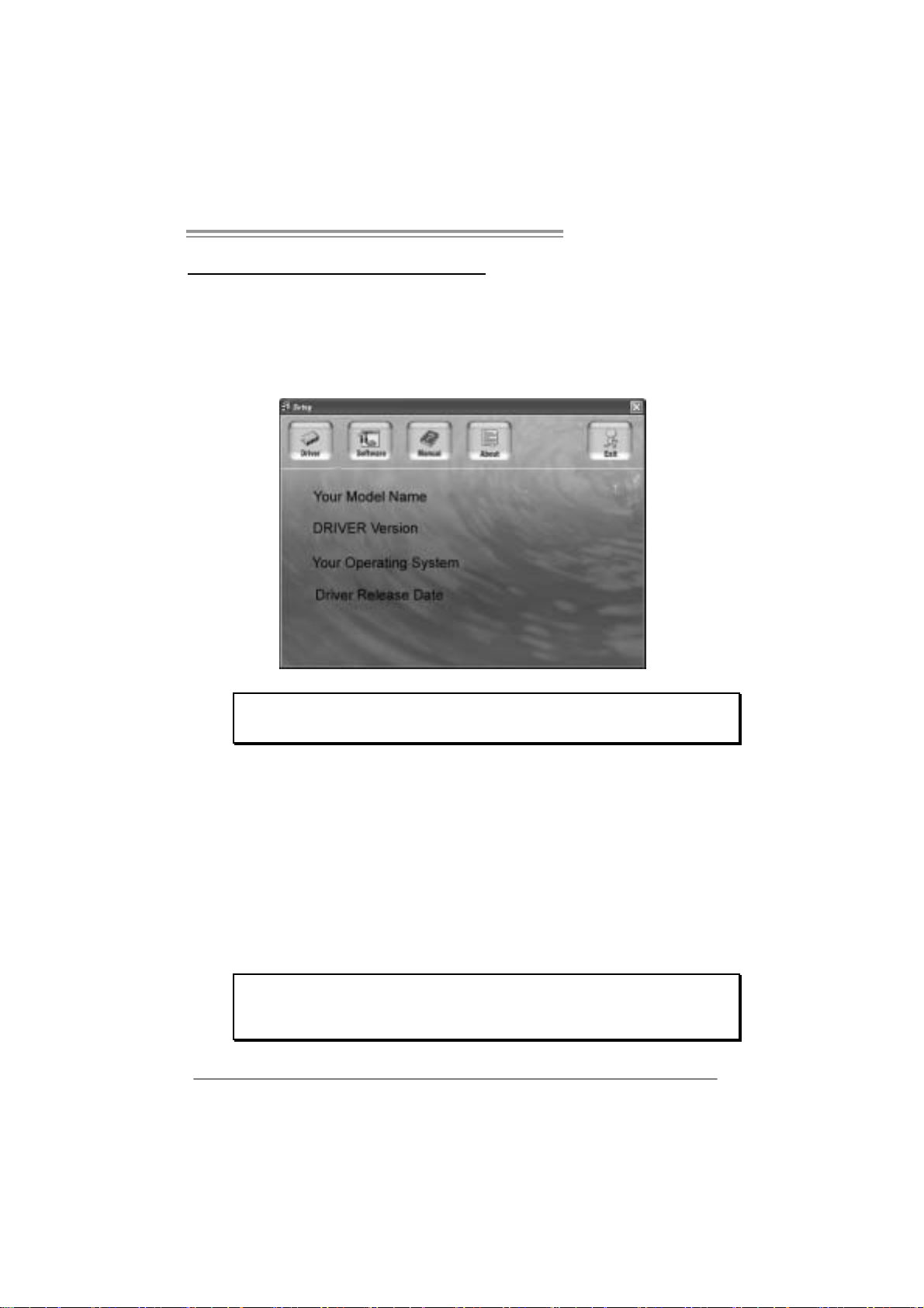
JSATA1~ JS ATA2: Serial ATA Co nnectors
The motherboard has a PCI to SATA Controller wit h 2 channels SATA interf ac e,
it satisfies the SATA 1.0 spec and with transfer rate of 1.5Gb/s.
Pin
1 Ground
2 TX+
3 TX4 Ground
5 RX-
JSATA2
147
JSATA1
6 RX+
7 Ground
Assignment
17
Page 18
Motherboard Manual
JSP DIF_OUT1: Di gital Audio-out Con nec tor
This connector allows user t o connec t the PCI bracket SPD IF output header.
Pin
Assignment
1 +5V
2 SPDIF_OUT
3 Ground
13
18
Page 19
P4M890-M7 PCI-E
CHAPTER 4: USEFUL HELP
4.1 DRIVER IN STALLATION NOTE
After you installed your operating system, please insert the Fully Setup
Driver CD into your optical drive and install the driver for better system
performance.
You will see the following window after you insert the CD
The setup guide will auto detect your motherboard and operating system.
Note:
If this window didn’t show up after y ou insert the Driver CD, please use file browser to
l ocate an d e xecute the fil e SETU P.EXE under yo ur o pt i cal dr i ve .
A. Driver Insta ll ation
To install the driver, please click on the Driver icon. The setup guide will
list the compatible driver for your motherboard and operating system.
Click on each device driver to launch the installation program.
B. Software Installation
To install the software, please click on the Software icon. The setup guide
will list the software available for your system, click on each software title
to launc h th e ins ta llatio n progr a m.
C. Manual
Aside from the paperback manual, we also provide manual in the Driver
CD. Click on the Manual icon to browse for available manual.
Note:
You will need Acroba t Reader to open the m anual file . Please download the la te s t ve rsion
of Acrobat Rea der so ftware from
http://www.adobe.com/products/acrobat/readstep2.html
19
Page 20
Motherboard Manual
4.2 AWARD BIOS BEEP CODE
Beep Sound Meaning
One long beep f ollowed by t wo s hort
beeps
High-low siren sound CPU overheated
One Short beep when system boot-up No error found during POST
Long beeps every ot her sec ond No DRAM detected or inst all
Video card not f ound or video card
mem ory bad
Sys t em will shut down autom at ically
4.3 EXTRA INFORMATION
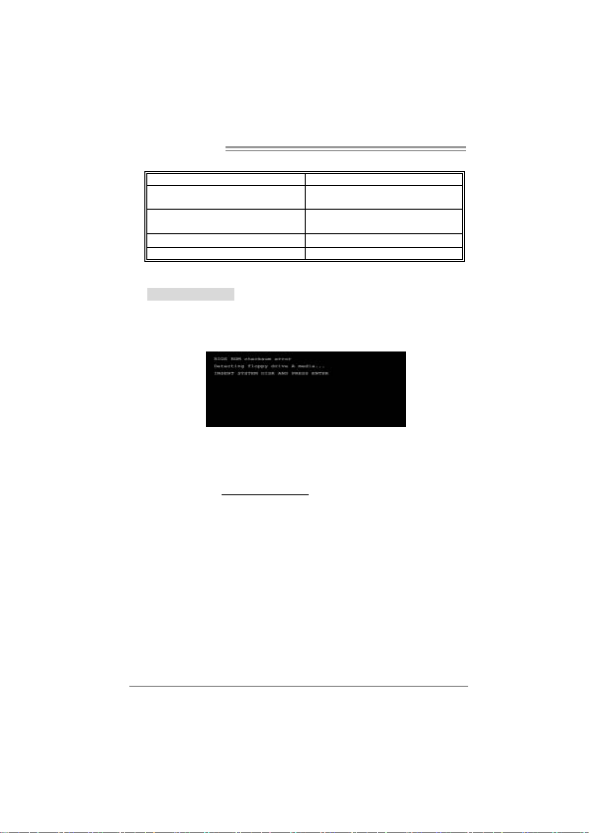
A. BIOS Update
After you fail to update BIOS or BIOS is invaded by virus, the
Boot-Block function will help to restore BIOS. If the following message
is shown after boot-up the system, it means the BIOS contents are
corrupted.
In this Case, please follow the procedure below to restore the BIOS:
1. Mak e a bo ot ab le flop py dis k.
2. Download the Flash Utility “AWDFLASH.exe” from the Biostar
website: www.biostar.com.tw
3. Confirm motherboard model and dow nload the respectively BIOS
from B ios tar w ebs it e.
4. Copy “AWDFLASH.exe” and respectively BIOS into floppy disk.
5. Insert the bootable disk into floppy drive and press Enter.
6. System will boot-up to DOS prompt.
7. Type
“Awdfla sh xxxx.bf / sn/py/ r” in DOS prompt.
(
xxxx means BIOS name.)
8. System will update BIOS automatically and restart.
9. The BIOS has been recovered and will work properly.
20
Page 21

P4M890-M7 PCI-E
B. CPU Overheated
If the system shutdown automatically after power on system for
seconds, that means the CPU protection function has been activated.
When the CPU is over heated, the motherboard will shutdown
automatically to avoid a damage of the CPU, and the system may not
power on again.
In this case, please double check:
1. The CPU cooler surface is placed evenly with the CPU surface.
2. CPU fan is rotated normally.
3. CPU fan speed is fulfilling with the CPU speed.
After confirmed, please follow steps below to relief the CPU protection
function.
1. Remove the power cord from power supply for seconds.
2. Wait for seconds.
3. Plug in the power cord and boot up the system.
Or you can:
1. Clear the CMOS data.
(See “Close CMOS Header: JCMOS1” section)
2. Wait for seconds.
3. Power on the system again.
21
Page 22

Motherboard Manual
e
4.4 TROUBLESHOOTING
Probable Solution
1. No power to the system at all
Power light don’t illuminat e, f an
inside power s upply does not t urn
on.
2. Indic at or light on key board does
not t urn on.
Sys t em inoperat iv e. Key board lights
are on, power indic at or lights are lit,
and hard driv e is spinning.
Sys t em does not boot from hard disk
drive, can be boot ed from optical drive.
Sys t em only boots from optical drive.
Hard disk can be read and applicat ions
can be used but booting f rom hard dis k
is imposs ible.
Screen m essage say s “Invalid
Conf igurat ion” or “CMOS Failure.”
Cannot boot sys t em af t er inst alling
sec ond hard drive.
1. Make sure power c able is
sec urely plugged in.
2. Replace cable.
3. Contact technical support.
Us ing even pres s ure on both ends of
the DIMM, press down firm ly unt il the
module s naps int o place.
1. Chec k cable running from disk t o
disk controller board. Make sure
both ends are s ec urely plugged
i n; c h ec k t h e driv e t y pe in the
standard CMOS se tup.
2. Back ing up the hard drive is
ext rem ely im port ant. All hard
disk s are c apable of break ing
down at any t ime.
1. Back up data and applications
files.
2. Ref orm at t he hard drive.
Re-ins t all applicat ions and dat a
using backup disks.
Rev iew sys t em’s equipment . Make s ur
correc t inf orm at ion is in setup.
1. Set m aster/slave jum pers
correctly.
2. Run SETUP program and s elect
correc t driv e types. Call t he drive
manufac turers for compatibili t y
with other drives.
22
Page 23

P4M890-M7 PCI-E
CHAPTER 5: WARPSPEEDER™
5.1 INTRODUCTION
[WarpSpeeder™], a new powerful control utility, features three
user-friendly functions including Overclock Manager, Overvoltage
Manager, and Hardware Monitor.
With the Overclock Ma nager, users can easily adjust the frequency they
prefer or they can get the best CPU performance with just one click. The
Overvoltage Manager, on the other hand, helps to power up CPU core
vol tag e an d Me mory v ol ta ge. Th e co o l Har dw ar e Mo ni tor smart ly in d icat es
the temperatures, voltage and CPU fan speed as well as the chipset
information. Also, in the About panel, you can get detail descriptions about
BIOS model and chipsets. In addition, the frequency status of CPU,
memory, AGP and PCI along with the CPU speed are synchronically
s how n on our ma in pan el .
Moreover, to protect users' computer systems if the setting is not
appropriate w h en testing and results in system fail or hang,
[WarpSpeeder™] technology assures the system stability by automatically
rebooting the computer and then restart to a speed that is either the
original system speed or a suitable one.
5.2 SYSTEM REQUIREMENT
OS Support: Windows 98 SE, Windows Me, Windows 2000, Windows XP
DirectX: DirectX 8.1 or above. (The Windows XP operating system
includes DirectX 8.1. If you use Windows XP, you do not need to install
D ir ectX 8. 1.)
23
Page 24
Motherboard Manual
5.3 INSTALLATION
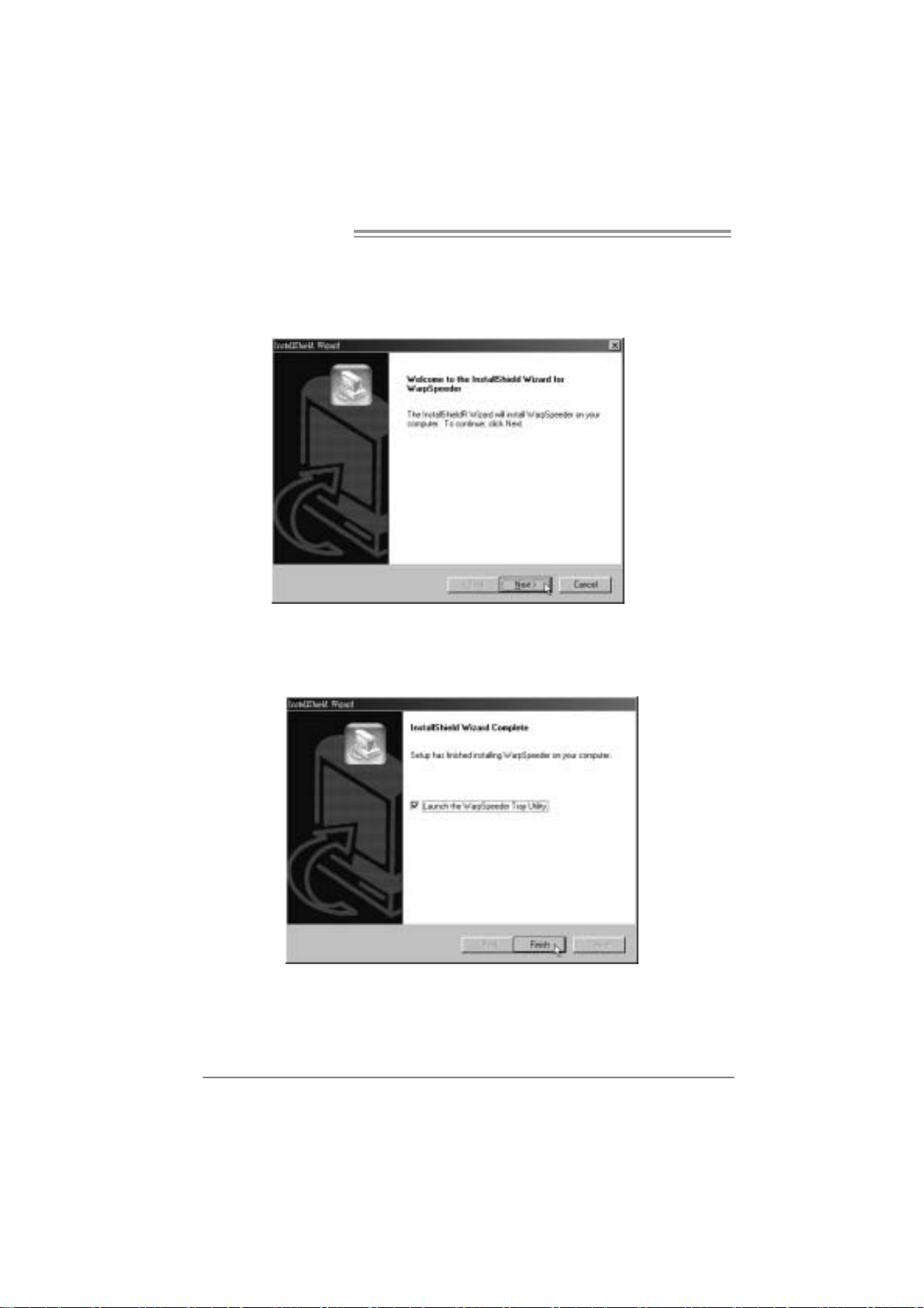
1. Execute the setup execution file, and then the following dialog will pop
up. Please click “Next” button and follow the default procedure to
install.
2. When you see the following dialog in setup procedure, it means setup
is completed. If the “Launch the WarpSpeeder Tray Utility” checkbox
is checked, the Tray Icon utility and [WarpSpeeder™] utility will be
automatically and immediately launched after you click “Finish”
button.
Usage :
The following figures are just only for reference, th e screen printed in
this user manual will change according to your motherboard on hand.
24
Page 25
P4M890-M7 PCI-E
5.4 WARPSPEEDER™
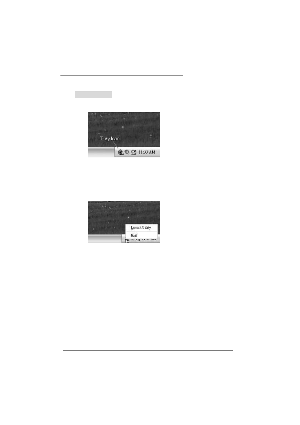
1. Tray Icon:
Whenever the Tray Icon utility is launched, it will display a little tray
icon on the right side of Windows Taskbar.
This utility is responsible for conveniently invoking [WarpSpeeder™]
Utility. You can use the mouse by clicking the left button in order to
invoke [WarpSpeeder™] directly from the little tray icon or you can
right-click the little tray icon to pop up a popup menu as following
figure. The “Launch Utility” item in the popup menu has the same
function as mouse left- click on tray icon and “Exit” item will close
Tray Icon utility if selected.
25
Page 26
Motherboard Manual
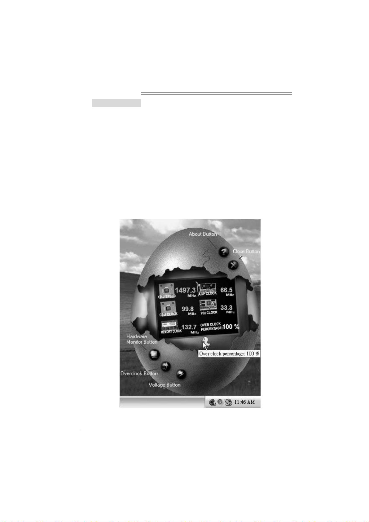
2. Main Panel
If you click the tray icon, [WarpSpeeder™] utility will be invoked.
Please refer to the following figure; the utility’s first window you will
see is Main Panel.
Main Pane l conta ins features as follows:
a. Displ ay the CPU Speed, CPU external cl ock, Memory clock, AGP clock,
and PCI clock information.
b. Contains About, Voltage, Overclock, and Hardware Monitor Buttons for
invoking respective panels.
c. W ith a us er - frie nd ly St atus An im at io n, it c an r epr es ent 3 over cloc k
percentage stages:
Man walking
Panther running
Car racing
→overclock percentage from 100% ~ 110 %
→overclock percentage from 110% ~ 120%
→overclock percentage from 120% ~ above
26
Page 27
P4M890-M7 PCI-E
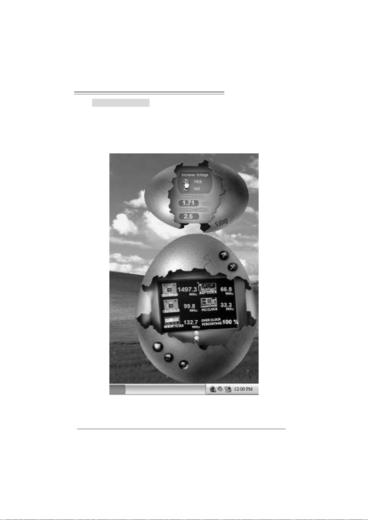
3. Voltage Panel
Click the Voltage button in Main Panel, the button will be highlighted
and the Voltage Panel wil l slide out to up as the following figure.
In this panel, you can decide to increase CPU core voltage and
Memory voltage or not. The default setting is “No”. If you want to get
the best performance of overclocking, we recommend you click the
option “Yes”.
27
Page 28
Motherboard Manual
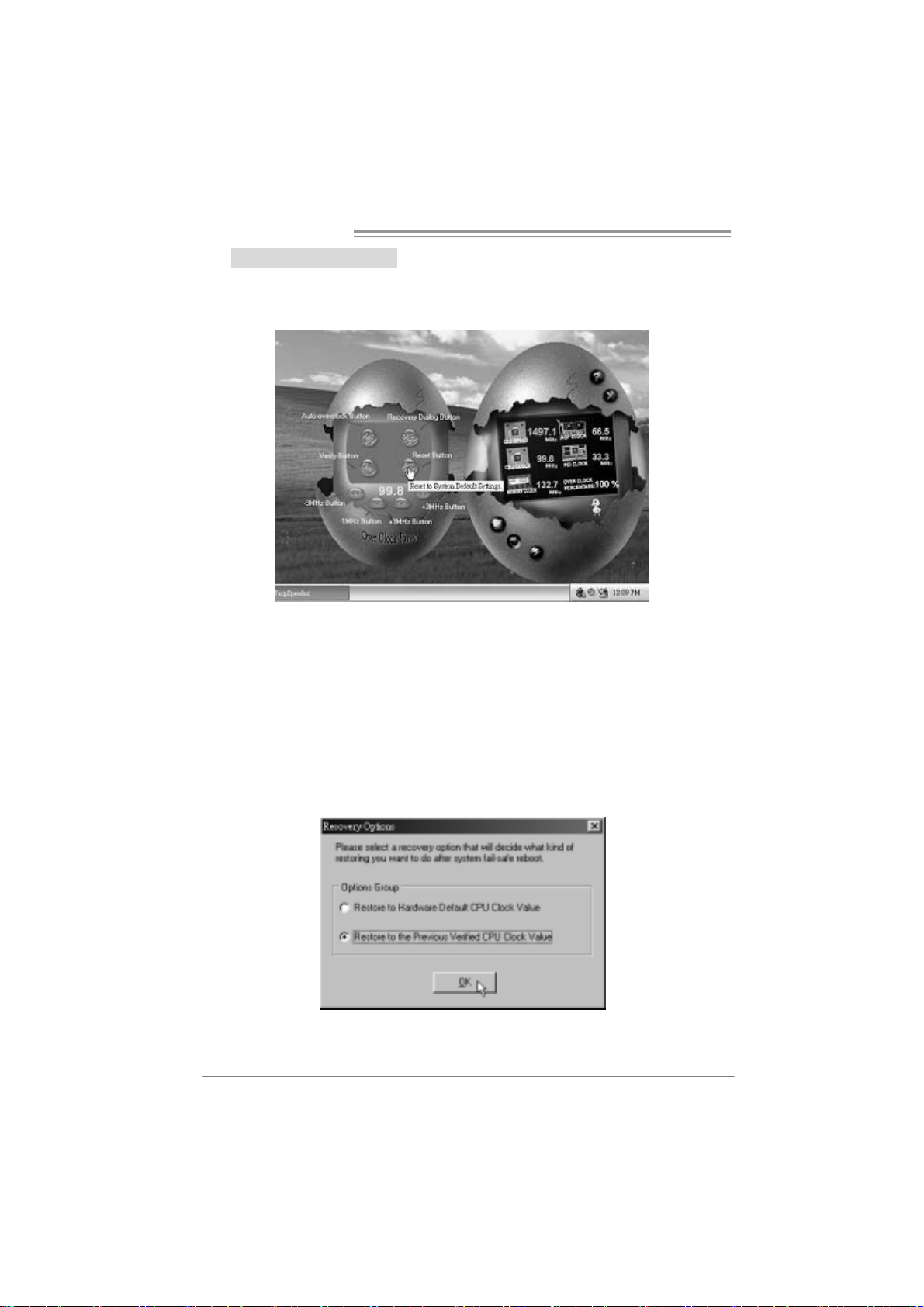
4. Over clock Pa nel
Click the Overclock button in Main Panel, the button will be
highlighted and the Overclock Panel will slide out to left as the
foll owi ng figur e .
Overclock Panel cont ains the the se feature s:
a. “–3MHz button”, “-1MHz button”, “+1MHz button”, and “+3MHz button”:
provide user the ability to do real-time overclock adjustment.
Warning:
Manually overclock is pot entially dangerous, especially when the
overclocking percent age is ov er 110 %. We s t rongly rec ommend you
verify every speed y ou overclock by c lick the Verify butt on. Or, you c an
just click Aut o overclock button and let [W arpSpeeder™] aut om atically
gets the best result for y ou.
b. “Recovery Dialog button”: Pop up the following dialog. Let user select
a restoring way if system need to do a fail-safe reboot.
28
Page 29

P4M890-M7 PCI-E
c. “Auto-overclock button”: User can click this button and
[WarpSpeeder™] will set the best and stable performance and
frequency automatically. [WarpSpeeder™] utility will execute a
series of testing until system fail. Then system will do fail-safe
reboot by using Watchdog function. After reboot, the
[WarpSpeeder™] utility will restore to the hardware default
setting or load the verified best and stable frequency according
to the Recovery Dialog’s setting.
d. “Verify button”: User can click this button and [WarpSpeeder™]
will proceed a testing for current fr equency. If the testing is ok,
then the current frequency will be saved into system registry. If
the testing fail, system will do a fail-safe rebooting. After reboot,
the [WarpSpeeder™] utility will restore to the hardware default
setting or load the verified best and stable frequency according
to the Recovery Dialog’s setting.
Note:
Becaus e the t esting programs, inv ok ed in Auto-overclock and Verif y,
include D irectDraw, D irect3D and D irectShow t ests, the D irectX 8.1 or
newer runtime library is required. And please m ak e sure y our display
card’s color depth is High color (16 bit) or True c olor( 24/32 bit ) that is
required for Direc t3D rendering.
5. Hardware Monitor Panel
Click the Hardware Monitor button in Main Panel, the button will be
highlighted and the Hardware Monitor panel will slide out to left as
the fo llow ing f igur e.
In this panel, you can get the real-time status information of your
system. The information will be refreshed every 1 second.
29
Page 30

Motherboard Manual
6. About Panel
Click the “about” button in Main Panel, the button will be highlighted
and th e Ab out Pa ne l will s l ide out to up as the fo l lowin g fig ure.
In this panel, you can get model name and detail information in hints
of all the chipset that are related to overclocking. You can also get
the mainboard’s BIOS model and the Version number of
[WarpSpeeder™] utility.
30
Note :
Because the overclock, overvoltage, and hardware monitor features
are controlled by several separate chipset, [WarpSpeeder™] divide
these features to separate panels. If one ch ipset is not on board, the
correlative button in Main panel will be disabled, but will not interfere
other panels’ functions. This property can make [WarpSpeeder™]
util ity m ore rob us t.
Page 31

P4M890-M7 PCI-E
This page is intentionally left blank
31
Page 32

Motherboard Manual
/
g /
APPENDENCIES: SPEC IN OTHER LANGUAGE
GERMAN
Spezifikationen
LGA 77 5
Intel Core2Duo
CPU
FS B 533 / 800 / 106 6 MHz
Chipsatz
Grafik Integrierter UniChrome Pro Chipsatz
Super E/A
Arbeitsspeic
her
IDE
SATA
LAN PHY Realtek RTL 8201CL
Audio-Code
c
Steckplätze
Onboard-An
schluss
/ Celeron D Prozessoren mit bis zu 3,8
GHz
*It is recommende d to use processors
with 95W power consum pti on.
VIA P4M890
VIA VT8237R+
ITE 871 2F
Biet et die h äufi g verwe ndeten alten
Super E/A-Funktione n.
Low Pin C ount-Sc hnit ts telle
DDR2 DIMM-St eckplät ze x 2
Unterstützt DDR2 400 / 533
Jeder DIMM unterstützt
256/512MB /1GB/2GB DDR2.
Max. 4GB Arbeitsspeicher
Integrierter IDE-Controller
Ultra DMA 33 / 66 / 100 / 133Bus
Master-Modus
Integrierter Serial ATA-Controller
Datentransferr ate bis zu 1. 5Gb/s
AL C 655 / 658
PCI-Steckplatz x2
PCI Expr ess x16 Steckplatz x1
PCI Expr ess x 1-St eckplatz x1
Diskettenlaufwerk anschluss x1
IDE-Anschluss x2 Jeder Anschluss unterstützt 2 IDE-Laufwerke
SATA-Anschluss x2 Jeder Anschluss unterstützt 1 SATA-Laufwerk
Fronttafelanschluss x1 Unterstützt die Fronttafelfunktionen
Pe ntium 4 / Pe ntium D
Unterstützt Hyper-Threadin
Bit / Enhanced I ntel SpeedStep® / Intel
Architecture-64 / Exte nded Memory 64
Technol ogy
Max. 64MB gemeinsam benutzter
Vi deospeicher
Umgebungs kontroll e,
Hardware-Überwachung
Lüfterdrehzahl-Controller
"Smart Guar dian"-Funktion von ITE
Ein-Kanal D DR2 S peichermodul
registrierte DIMMs. Nicht-ECC DIMMs werden
nicht unterstützt.
Unterstützt PIO-Modus 0~4,
Konform mit der SATA-Spezifikation Version
1.0.
10 / 1 00 Mb/s A uto-Negotiation
Halb-/ Vollduplex-Funktion
6-Kanal-Au dioausg abe
AC ’97 V ersion 2.3
Jeder A nschluss unterstützt 2
Diskettenlaufwerke
Execute Dis able
32
Page 33

P4M890-M7 PCI-E
Spezifikationen
Unterstützt die
Fronttafel-Audioanschlussfunktion
CPU-Lüfterstromversorgungsanschluss (mit
Smart Fan-Funktion)
Fronttafel-USB-Anschlüsse
Biostar behält sich das Recht vor, ohne
Ankündigung die Unterstützung für ein
Betriebs syst em hinzuzufü gen oder z u
entfernen.
RückseitenE/A
Platinengr ö
ße.
OS-Unterst
ützung
Front-Audioanschluss x1
CD-IN-Anschluss x1 Unterstützt die CD Audio-In-Funktion
S/PDIF-A usgangs ansc hlus s x1 Unterstützt die di gitale Audioausg abefunkt ion
CPU-Lüfter-Sockel x1
System-Lüfter-Sockel x1 System-Lüfter-Stromversorgungsanschluss
"CMOS löschen"-Sockel x1
USB-Anschluss x2 Jeder Anschluss unterstützt 2
Stromanschluss (24-polig) x1
Stromanschluss (4-polig) x1
PS/2-Tas tatur x1
PS/2-Maus x1
Serieller Anschluss x1
Druckeranschluss x1
VGA-Anschluss x1
LAN-Anschluss x1
USB-Anschluss x4
Audioanschluss x3
190 mm (B) X 244 mm (L)
Windows 2K / XP
33
Page 34

Motherboard Manual
/
jusq
p
p
/
q
FRANCE
LGA 77 5
Processeurs Intel Core 2Duo
UC
Bus frontal 533 / 800 / 106 6 MHz
Chipset
Graphi ques Integré dans l a chipset U niChrome
Super E/S
Mémoire
principale
IDE
SATA
LAN PHY Realtek RTL 8201CL
Codec
audio
Connect eu
r
embarqué
4 / Pent ium D / Celer on D
GHz
*It is recommende d to use
with 95W power consum pti on.
VIA P4M890
VIA VT8237R+
Pro
ITE 871 2F
Four nit la fonctionnal it é de Su
patrimoniales la plus utilisée.
Interface à faible compte de broc hes
Fent es DDR 2 DIMM x 2
Prend en charge la DDR 2 400 / 533
Chaque DIMM pren d en ch arge des
DDR2 d e 256 Mo /512 Mo / 1Go / 2 Go
Capacité mémoire maximale de 4 Go
Contrôleur IDE int égr é
Mode principale de Bus Ultra DMA 33
66 / 1 00 / 133
Contrôleur Serial ATA intégré :
Taux de transfert jusqu'à 1.5 Go/s.
AL C 655 / 658
Fente PCI x2
Slot PCI Express x16 x1 Fentes
Slot PCI Express x 1 x1
Connec teur de di squ ette x1
Connect eur IDE x2
Connect eur SATA x2
Connect eur du panneau avant x1
34
Pentium
u'à 3,8
rocessors
er E/S
S PEC
Prend en charge les technologies
Hyper -Threadin g / d'ex écut ion de bit de
désactivation / I ntel SpeedStep® optimisée/
d'architecture Intel 64 / de mémoire éte ndu e 64
Mémoire vidé o partagée maximale de 64 Mo
Initiatives de co ntrôle e nvironnementales,
Moniteur de mat ériel
Contrôleur de vites se de vent ilateur
Fonction " Gardien i ntelligent" de l'ITE
Module de mém oire DDR2 à mode à simple v oie
Les DIMM à registres et DIMM sans code
correcteurs d'erreurs ne sont pas prises en
charge
Prend en charge le mode PIO 0~4,
Conforme à la spécification SATA Version 1.0
10 / 100 Mb/s négociation automatique
Half / Full duplex capability
Sortie audio à 6 voies
AC ’97 V ersion 2.3
ue connect or prend en charge 2 lecteurs de
Cha
disquettes
Chaque con necteur pren d en c har ge 2
péri phéri ques I DE
Chaque con necteur pren d en c har ge 1
périphérique SATA
Prend en charge les équipements du panneau
avant
Page 35

P4M890-M7 PCI-E
q
S PEC
E/S du
pann eau
arrière
Dim ension
s de la
carte
Suppor t
SE
Connect eur Audio du p anneau
avantx1 x1
Connecteur d'entré e CD x1 Prend en charge l a fonction d'entrée audio d e CD
Connecteur de sortie S/PDIF x1
Embase de ve nti lat eur UC x1
Embase d e ventilateur s ystème x1 Alimentation électrique du ve ntilateur syst ème
Embas e d'e ffacem ent C MO S x1
Connect eur USB x2
Connecteur d'alimentation x1
(24 broches)
Connecteur d'aliment atio n x1
(4 broches)
Clavier PS/2 x1
Souris PS/2 x1
Port série x1
Port d'impri mant e x1
Port VGA x1
Port LAN x1
Port USB x4
Fiche audio x3
190 mm (l) X 244 mm (H)
Windows 2K / XP
Prend en charge la fonct ion audio d u panneau
avant
Prend en charge la fo nct ion de sor ti e audio
numériq ue
Alimentation électrique du ventilateur UC (avec
fonction de ventilateur intelligent)
ue connect eur prend en charge 2 ports USB
Cha
de panneau avant
Biostar se réserve le droit d'ajo uter ou de
supprimer le su pport de SE av ec ou s ans préavis .
35
Page 36

Motherboard Manual
p
ITALIAN
SPECIFICA
LGA 77 5
Processore Intel Core2Duo/ Pentium
CPU
FS B 533 / 800 / 106 6 MHz
Chipset
Grafica Integrata nel Chi ps et UniC hrome Pr o La memoria vi deo condivisa massima è di 64MB
Super I/O
Memoria
principale
IDE
SATA
LAN PHY Realtek RTL 8201CL
Codec
audio
Alloggi Alloggio PCI x2
4 / Pent ium D / Celer on D fi no a 3.8
GHz
*It is recommende d to use
with 95W power consum pti on.
VIA P4M890
VIA VT8237R+
ITE 871 2F
Fornisce le funzionalità legacy Super
I/O us ate più com unement e.
Interfaccia LPC (L ow Pin Count)
Al loggi DIMM DDR 2 x 2
Supporto di DDR2 400 / 533
Ci ascun DIMM su pporta DDR 2 256MB
/512MB / 1GB / 2GB
Capacità massima della memoria 4GB
Controller IDE i ntegrato
Modalità Bus Master Ultra DMA 33 /
66 / 1 00 / 1 33
Controller Serial ATA integrato
Veloc it à di trasferim ento dei dati fi no
a 1.5 Gb/s .
AL C 655 / 658
rocessors
Suppor to di Hyper -T hreadi ng / Exec ute Disable
Bit / Enhanced I ntel SpeedStep® / Architettura
Intel 64 / Tecn ologia Exte nded Memory 64
Funzioni di controllo dell’ambiente:
Monitoraggio hardware
Controller velocità ventolina
Funz ione "Smart G uardi an" di I TE
Modulo di memoria DDR 2 a can ale sin golo
DIM M regis tr ati e DIMM No n-ECC no n sono
supportat i
Suppor to modalità PIO Mode 0-4
Compatibile specifiche SATA Versione 1.0.
Negoziazi one aut omatica 10 / 10 0 Mb /s
Capacità Half / Full Duplex
Uscita audio 6 canali
AC ’97 V ersione 2.3
36
Page 37

P4M890-M7 PCI-E
(
SPECIFICA
Al loggio PCI Express x1 6 x1
Al loggio PCI Express x1 x1
Connett ore flo ppy x1 Ciasc un conn ett ore sup porta 2 unità Floppy
Connett ore IDE x2 Ci ascun c onn ettore sup port a 2 unità IDE
Connett ore SA TA x2 C ias cun conn ett ore sup porta 1 uni tà SA TA
Connettore pannello frontale x1 Supporta i servizi del pa nnell o fr ontale
Connettore audio frontale x1 Supporta la funzione audio pannello frontale
Connett ore CD-i n x1 S upporta la funzione i nput au dio C D
Connett ore outp ut S PDIF x1 S upporta la fu nzione d’out p ut a udio digitale
Connett ori
su scheda
I/O
pannello
posteriore
Dim ension
i scheda
Sistemi
operativi
supportat i
Collettore ventolina CPU x1
Collettore ventolina sistema x1 Alimentazione ventolina di sistema
Collettore cancellazione CMOS x1
Connett ore USB x2
Connettore alimentazione x1
(24 pin)
Connettore alimentazione x1
(4 pin)
Ta s t i e r a PS / 2 x 1
Mouse PS/2 x1
Porta seriale x1
Porta s tampant e x1
Porta VGA x1
Porta LAN x1
Porta USB x4
Connett ore au dio x3
19 0 mm (l argh ez za) x 244 mm
(altezza)
Windows 2K / XP
Alimentazione v ent olina C PU
Fan)
Ciascun connettore supporta 2 porte USB
pannello frontale
Biostar si riserva il diritto di aggiu ngere o
rimuovere il supporto di qualsiasi sistema
operativo se nza pre avvis o.
c on f unz io ne S m art
37
Page 38

Motherboard Manual
p
j
/
SPANISH
Especificación
LGA 77 5
Procesador I ntel Core2Duo/ Pentium
CPU
FS B 533 / 800 / 106 6 MHz
Conjunto
de chips
Gráfi cos
Súper E/S
Memoria
principal
IDE
SATA
Red Local Realtek RTL 8201CL
Códecs de
sonido
Conectore
s en placa
4 / Pent ium D / Celeron D hast a 3, 8
GHz
*It is recommende d to use
with 95W power consum pti on.
VIA P4M890
VIA VT8237R+
Integrados en el conjunto d e chips
UniChrom e Pro
ITE 871 2F
Le ofrece las funcionalidades
heredadas de uso más común Súper
E/S.
Interfaz de cue nta Low Pin
Ranuras DIMM DDR 2 x 2
Admite DDR2 de 400 / 533
Cada DI MM admite DDR de 256MB
/512MB /1GB / 2GB
Capacidad máxima de memoria de
4GB
Controlador ID E integrado
Modo bus m aes tr o Ult ra DMA 33 / 66
100 / 133
Controlador ATA Serie Integrado
Tasas de transferencia de hasta 1.5
Gb/s .
ALC 65 5 / 6 58
Ranura PCI X 2
Ranura PCI Ex press x1 6 X1 Ranuras
Ranura PCI ex pres s x 1 X1
Conector disco flexible X1
Conector IDE X2 Cada conector soporta 2 dispositivos IDE
Conector SATA X2 Cada conector soporta 1 dispositivos SATA
rocessors
Admite Hyper-Threading / Bit de deshabilitación
ec uci ó n / Intel SpeedStep® Mejorad o / Intel
de e
Architecture-64 / Tecnología Extended Memory
64
Memoria máxima de vídeo compartida de 64MB
Iniciativas de control de entorno,
Monitor hardware
Cont rolador de velocidad d e ve ntilador
Función "Guardia inteligente" de I TE
Módulo de memoria DDR2 de canal Sencillo
No admite DIMM registrados o DIMM no
compatibles con ECC
Soporte los Mo dos PIO 0~ 4,
Compatible con la versión SATA 1.0.
Negociaci ón de 10 / 100 Mb/s
Funciones Half / Full d úplex
Salida de sonido de 6 canales
AC ’97 Versi ón 2.3
Cada con ector soporta 2 uni dades de disco
flexible
38
Page 39

P4M890-M7 PCI-E
Especificación
Conector de panel frontal X1 Soporta instalaciones en el panel fr ontal
Conect or de soni do frontal X1 S oporta funcio nes de sonid o e n el pa nel frontal
Conector de entr ada de C D X 1 Soporta funció n de e ntrada de s onido de CD
Conector de salida S/PDIF X 1 Soporta funció n de salida de s onido di gital
Cabecera de ve ntilador de C PU X1 Fuente de alime ntac ión de ve ntilador de CPU (con
funció n Sm art Fan)
Panel
trasero de
E/S
Ta m añ o de
la placa
Soporte de
sistema
operativo
Cabecera de ve ntilador de
sistema X1
Cabecera de borrado de CMO S X1
Conector USB X2 Cada conector soporta 2 puertos USB frontales
Conector de alimentación X1
(24 patillas)
Conector de alimentación X1
(4 patillas)
Te c lado P S / 2 X 1
Ratón PS/2 X1
Puerto s erie X1
Puert o de im pr esora X1
Puerto VGA X1
Puert o de re d local X 1
Puerto US B X4
Conector de sonido X3
190m m. (A) X 244 Mm. (H)
Windows 2K / XP
Fuente de alimentación de ventilador de sistema
Biostar s e reserva el derecho de aña dir o r etirar el
soporte de cualquier SO con o sin aviso previo.
39
Page 40

Motherboard Manual
/
/
p
/
ç
PORTUGUESE
ESPE CIFICAÇÕES
LGA 77 5
Processador Intel Core2Duo
CPU
FS B 533 / 800 / 106 6 MHz
Chipset
Placa
gráfica
Especificaç
ão Sup er
I/O
Memória
principal
IDE
SATA
LAN PHY Realtek RTL 8201CL
Codec de
som
Conectore
s na placa
4 / Pentium D / Celeron D até 3, 8 GHz
*It is recommende d to use processors
with 95W power consum pti on.
VIA P4M890
VIA VT8237R+
Integrada no c hips et UniChrome Pro Mem ória de víde o máxima part ilhada: 64 MB
ITE 871 2F
Proporciona as funcionalidades mais
utilizadas em termos da es
Super I/O.
Int erface L PC (Low Pi n Co unt).
Ranhuras DIMM DDR2 x 2
Suporta módulos DDR2 400 / 533
Cada mó dulo DIMM su port a uma
me mó ri a D DR 2 d e 25 6MB /5 12 M B / 1
GB / 2GB
Capacidade máxima de memória : 4
GB
Controlador ID E integrado
Modo Bus master Ultra DMA 33 / 66
100 / 133
Controlador Serial ATA integrado
Velocidades de transmissão de dados
até 1.5 Gb/s.
AL C 655 / 658
Ranhura PCI x2
Ranhura PCI Express x 16 x1 Ranhuras
Ranhura PCI Express x 1 x1
Conector da unida de de
disquetes x1
Conector IDE x2 Cada conector suporta 2 dispositivos IDE
Conector SATA x2 Cada conector suporta 1 dispositivo SATA
Conect or do pai nel fro ntal x1 Para suporte de vár ias funções n o painel fro ntal
40
Pentium
ecificação
Suporta as tec nologias Hyper -Threa ding /
Execute Dis able Bit
/ Intel Arquitecture -64 / Extended Memory 64
Iniciativas para control o do ambiente
Monitorização do hardware
Cont rolador da velocidade da ventoin ha
Função "Smart Guardia n" da I TE
Módul o de memória DDR 2 de canal simples
O s m ó d u l o s D I M M r e g i s t a d o s e o s D I M M N o n - E C C
não são suportados
Suporta o modo PIO 0~4,
Compatibilidade c om a especifica
1.0.
Auto ne goc iação de 10 / 10 0 M B/s
Capacidade semi/full - dupl ex
Saída de á udio de 6 c a nais
AC ’97 V ersão 2. 3
Cada conector suporta 2 unidades de disquetes
En hanc ed I nt el SpeedStep®
ão SATA versão
Page 41

P4M890-M7 PCI-E
ç
p
ESPE CIFICAÇÕES
Conector de áu dio fro ntal x1 Suporta a f unção de áudio no pai nel fr ontal
Conector para entrada de C Ds x1 Suport a a e ntrada de áudi o a partir de C Ds
Conector de saída S/PDIF x1 S uporta a saí da de áudio digital
ão da vent oi nha da CPU (com a função
orte par a qualquer sistema operativo
Entradas/
Saídas no
painel
traseiro
Ta m a n h o
da pl aca
Sistemas
operativos
suportado
s
Conect or da ve ntoi nha da CPU x1
Conect or da ventoi nha do
sistema x1
Conector para lim peza do CMOS x1
Conector USB x2
Conector de alimentação x1
(24 pin os)
Conector de alimentação x1
(4 pinos)
Te c lado P S / 2 x 1
Rato PS/2 x1
Porta série x1
Porta para impressora x1
Porta VGA x1
Porta LAN x1
Porta USB x4
Tom ada de áu dio x3
190 mm (L) X 244 m m (A)
Windows 2K / XP
Alimenta
Smart Fan)
Alimentação da ventoinha do sistema
Cada con ector suport a 2 portas USB no pai nel
frontal
A Biostar reserva-se o direito de adicionar ou
remover su
com ou sem aviso prévio.
41
Page 42

Motherboard Manual
/
/
p
POLISH
SPEC
LGA 77 5
Procesor Intel Core2D uo
Procesor
FS B 533 / 800 / 106 6 MHz
Chipset
Grafika
Pamięć
główna
Super I/O
IDE
SATA
LAN PHY Realtek RTL 8201CL
Kodek
dźwiękowy
Złącza
wbudowan
e
Pentium D / Celeron D do 3,8 GHz
*It is recommende d to use
with 95W power consum pti on.
VIA P4M890
VIA VT8237R+
Zintegrowana w chipsecie UniChrome
Pro
Gniaz da DDR 2 DIMM x 2
Obsługa DDR2 400 / 533
Każde gniazd o DIMM obsługuje
moduły 25 6MB / 512MB / 1GB / 2GB
DDR2
Maks. wielkość pamięci 4GB
ITE 871 2F
Zapewnia najbardzi ej powsz echne
funkc je S uper I/O.
Interfejs Low Pin Count
Zi ntegrowany kont rol er ID E
Ultra DMA 33 / 66 / 100 / 133 Tryb
Bus Master
Zi ntegrow any kont rol er Serial ATA
Transfer danych do 1.5 Gb/s.
AL C 655 / 658
Gniazdo PCI x2
Gniazdo PCI Express x16 x1 Gniaz da
Gniazdo PCI Express x 1 x1
Złącze napędu dyskietek x1 Każde złącze obsługuje 2 na pędy dyskietek
Złącze IDE x2 Każde z łącze obsług uje 2 urządze nia I DE
Złącze SATA x2 Każde złącze obsługuje 1 ur ządzenie SATA
Złącze panel a przedniego x1 O bsługa eleme ntów panela prz ed niego
Przednie złącze audio x1 Obsługa f unkc ji audio na pa nelu przedni m
Pentium 4
rocessors
42
Obsługa Hy per-Threading / Execute Disabl e Bit /
Enha nced Intel Sp eedS tep® / I ntel
Architecture-64 / Exte nded Memory 64
Technol ogy
Maks. wielkość współdzielonej pamięci video
wynosi 64MB
Moduł pamięci DDR2 z trybem poje dynczego
kanału
Brak obsługi Registered DIMM oraz Non-ECC
DIMM
Funkcje kontroli warun ków prac y,
Monitor H/W
Kontroler prędkości wentylat ora
Funkcja ITE "Smart Guar dian"
obsługa PIO tryb 0~4,
Zgodność ze specyfikacją SATA w wersji 1.0.
10 / 100 Mb/s z automatyczną neg oc jac ją
szybkości
Działanie w trybie połowicznego / pełnego
dupleksu
6 ka nałowe wyjście audio
AC ’97 w wers ji 2.3
Page 43

P4M890-M7 PCI-E
SPEC
Złącze wejścia CD x1 Obsługa funkcji wejścia audio CD
Złącze wyjścia S/PDIF x1 Obsługa funkcji cyfrow ego wy jścia audi o
Back Panel
I/O
Wymiary
płyty
Obsluga
systemu
operacyjn
ego
Złącze główkowe wentylatora
procesora x1
Złącze główkowe wentylatora
systemowego x1
Złącze główkowe kasowani a
CMOS x1
Złącze USB x2
Złącze z as ilania (24 pi now e) x1
Złącz e zasilania (4 pinowe) x1
Klawiatura PS/2 x1
Mysz PS/2 x1
Port szeregowy x1
Port druk arki x1
Port VGA x1
Port LAN x1
Port USB x4
Gniazdo audio x3
190 mm (S) X 244 m m (W)
Windows 2K / XP
Zasilanie wentyl atora pr ocesora (z f unkcją Smart
Fan)
Zasilanie wentylatora systemowego
Każde złącze obsług uje 2 porty USB na pa nelu
prz ednim
Bi ost ar z astrz ega sobie prawo dodawania lu b
odwoływania obsługi dowolnego systemu
operacyjn ego bez powiadomie nia.
43
Page 44

Motherboard Manual
p
/
р
р
RUSSIAN
CPU
(централь
ны й
проц ес сор
)
FS B 533 / 800 / 106 6 МГц
Набор
микросхе
м
Графика
Основная
память
Super I/O
IDE
SATA
Локальна
я сеть
Звуковой
кодек
Встроенн
ый раз ъём
LGA 77 5
Процессор Intel Core2Duo/ Pentium
4 / Pentium D / Celeron D до 3.8 ГГц
*It is recommende d to use
with 95W power consum pti on.
VIA P4M890
VIA VT8237R+
Встроенная в набо р м икросхем
UniChrom e Pro
Слоты DDR2 DIMM x 2
Подде рж ка DDR2 400 / 533
Каждый модуль DIMM
поддержива ет 256M B / 512МБ / 1ГБ
/ 2ГБ DDR2
Максимальн ая ёмкость памя ти 4 ГБ
ITE 871 2F
Обес печива ет на ибо лее
использ уем ые дейс твующие
функциональные возмож ности
Super I/O.
Интерф ейс с низким количеством
выводов
Вс троенное устройство управления
вс трое нны ми интерфе йс ами
устройств
Вс троенное пос ледовате льное
устройство управле ния ATA
Realtek RTL 8201CL
AL C 655 / 658
Слот PCI x2
Слот PCI Express x16 x1 Слоты
Слот PCI Express x 1 x1
Разъём НГМД x1
Разъём IDE x2
rocessors
СПЕЦ.
Подде рж ка те хн оло гий Hyper-Thre ading /
Execute Dis able Bit
/ Intel Architecture-64 / Extended Memory 64
Technol ogy
Максимальн ая совместно исп ользуе мая видео
память составляет 64 МБ
Модуль памя ти с однока наль ны м режим ом
DDR2
Не подде
DIMM an d Non- ECC DIMM
Иниц иа ти вы по охране окружающей среды,
Аппара тный монитор
Регуля тор скор ости
Функция ITE "Smart Gu ardian"
(Интеллектуа льна я защ ита)
Режим "хозя ина" шины Ultra DMA 33 / 66 / 100
/ 1 33
Подде рж ка режима PIO 0~4,
скорос ть пер едач и дан ных до 1. 5 ги габ ит/с.
Соотве тств ие сп ец ификац ии SATA версия 1. 0.
Автоматическое согласование 10 / 100 Мб/с
Частич ная / пол ная дуплексна я сп особность
Шестика нальны й звуково й выхо д
AC ’97 Версия 2.3
Каждый
гибк их магн ит ных дисках
Каждый раз ъём подде рж ивае т 2 вст рое нны х
инт ерфейса накопителей
живает зарегистриров анны е модули
азъём п оддерживает 2 нако пи тел я на
En hanc ed I nt el SpeedStep®
44
Page 45

P4M890-M7 PCI-E
СПЕЦ.
Каждый раз ъём подде рж ивае т 1 ус тро йство
SATA
Подде рж ка звуковых функций на лицево й
пане ли
Подде рж ка выво да цифровой звуко вой
функции
Источн ик пи та ния для ве нтиля тора
ц ентра льного проц ес сора (с функцией
интеллектуально го вен тилятора)
Источн ик пи та ния для ве нтиля тора сис темы
Каждый раз ъём подде рж ивае т 2 USB-порта на
лицевой панели
Biostar сохраняет за собой прав о добавлять
или уда лять средства обес печения дл я OS с
или без предвар ит ельного увед омле ния.
Задн яя
пане ль
средств
ввода-выв
ода
Размер
пане ли
Подде рж к
а OS
Разъём SATA x2
Разъём на лицево й пане ли x1 Подде рж ка устро йств на лицевой па нел и
Входной звуковой раз ъём x1
Разъём вв ода дл я CD x1 Подде ржка фу нкции ввода для CD
Разъём вы вода для S/PDIF x1
Контактирующее приспос о бле ние
вентилятора центрального
процессора x1
Контактирующее приспос о бле ние
вентилятора системы x1
Открытое контак тирующее
прис пособл ение CMOS x1
USB-разъём x2
Разъем пит ан ия (24 вывод ) x1
Разъем пит ан ия (4 вывод) x1
Клавиатура PS/ 2 x1
Мышь PS/2 x1
Последо вате льный по рт x1
Порт подключения пр инт ера x1
Порт VGA x1
Порт LAN x1
USB-порт x4
Гнездо для по дключения
наушников x3
19 0 мм (Ш) X 244 мм (В)
Windows 2K / XP
45
Page 46

Motherboard Manual
/
g /
/
y
ARABIC
تﺎﻔﺻ اﻮﻤﻟ ا
LGA 77 5
تﺎﻴﻨﻘﺕ ﻢﻋﺪﺕHyper-Threadin
En ha nced I ntel Spee dStep® / Extende d
ﻻ ﻢﻋﺪﺕ ﻖﺋﺎﻗر ةﺮآاﺬﻟا DIMM ﺔﻠﺠﺴﻤﻟا ﻚﻠﺕو ﻲﺘﻟا ﻻ ﻖﻓاﻮﺘﺕ ﻊﻡ ECC
تﺎﺤﺘﻔﻟا
Execute Disable Bit
64 Technology
Memor
وةﺪﺣ ةﺮآ اذ DDR 2 ﺔﻳدﺎﺣأ ةﺎﻨﻘﻟا
ﻞﺋﺎﺳو ﻢﻜﺤﺘﻟا ﻲﻓ ﺔﺌﻴﺒﻟا:
ﺐﻗاﺮﻡ ﺔﻓﺮﻌﻤﻟ ﺔﻟﺎﺣ ةﺰﻬﺝﻷا
ﺐﻗاﺮﻡ ﻲﻓ ﺔﻋﺮﺳ ﺮﻤﻟاﺔﺣو
ﺔﻔﻴﻇو"Smart Guardian" ﻦﻡ ITE
ﻊﺿو ﻢﻋدPI O Mode 0~4
ﺔﻘﺑﺎﻄﻡ تﺎ ﻔﺹاﻮﻤﻟ SATA راﺪﺹﻹا 1. 0.
ﻲﺋﺎ ﻘﻠﺕ ضوﺎﻔﺕ10/100 ﺖﻳﺎﺑ ﺎﺠﻴﻡ /ﺔﻴ ﻥﺎﺙ
ﻞﻡﺎﻜﻟا جودﺰﻤﻟا ﻞﻘﻨﻟا ﺔﻴﻥﺎﻜﻡإ/ﻲﻔﺼﻨ ﻟا
6 تاﻮﻨﻗ جﺮﺨﻟ تﻮﺼﻟا
راﺪﺹﻹا 2. 3 ﻦﻡ AC ’97
ﻢﻋﺪﻳ ﻞآ ﺬﻔ ﻨﻡ ﻦﻴﻨﺙا ﻦﻡ ةﺰﻬﺝأ IDE
ﻢﻋﺪﻳ ﻞآ ﺬﻔ ﻨﻡ ﺪﺣ او ﻦﻡ ةﺰﻬﺝأ SATA
تﺎﺠﻟﺎﻌﻡIntel Core2Duo
Pentium D / Celeron D ﺑ ددﺮﺘ ﻳ ﻰﻟإ ﻞﺼ8. 3
*It is recommende d to use processors
with 95W power consum pti on.
ددﺮﺕ 5 33 / 800 / 1066 ﺰﺕﺮه ﺎﺠﻴﻡ
ﻖﺋﺎﻗر ﻲﻓ ﺔﺠﻡﺪﻡ UniChrom e Pr o ﺔﻌﺳ ﻰﺼﻗأ ﺔآﺮﺘﺸﻤﻟا ﻮﻳﺪﻴﻔﻟا ةﺮآاﺬﻟ 64 ﺖﻳ ﺎﺑ ﺎﺠﻴﻡ
ﻢﻋﺪﺕ ةﺮآاﺬﻟا ﻦﻡ عﻮﻥ DDR2 تﺎﻌﺳ 400 / 53 3 ﺎﺠﻴﻡ
ﻢﻋﺪﺕ ﻞآ ﺔﺤﺘﻓ DIMM ﻢﻋﺪﺕ ةﺮآاذ ﻦﻡ عﻮﻥ DDR2 ﺔﻌﺳ
256 ﺎﺠﻴﻡ ﺖﻳ ﺎ ﺑ /512 ﺎﺠﻴﻡ ﺖﻳﺎﺑ و1 ﺎﺠﻴﺝ ﺖﻳﺎﺑ / 2
ﺮﻓﻮﺕ ﺔﻔﻴﻇو Super I/O ﺮﺜآﻷا ًﺎﻡاﺪﺨﺘﺳا.
Low Pin Count Int erfac e
ﺕﻢﻋﺪ ﺔﻴﻨﻘﺕ
ﺔﻴﻨﻘﺘﺑ ﻞﻗﺎ ﻥU ltra DM A 33 / 66 / 10 0 / 133
ﻢﻋﺪﻳ ﻦﻴآﺮﺤﻡ صاﺮﻗﻸﻟ ﺔﻥﺮﻤﻟا
46
Penti um 4 /
ﺰﺕﺮه ﺎﺠﻴﺝ
VIA P4M890
VIA VT8237R+
ﺔﺤ ﺘﻓDDR2 DIMM دﺪﻋ4
ﺖﻳ ﺎ ﺑ
ﺎﺠﻴﺝ ﺖﻳﺎﺑ
ﺔﻌﺳ ةﺮآاذ ىﻮﺼﻗ 4 ﺎﺠﻴﺝ ﺖﻳ ﺎ ﺑ
ITE 871 2F
ﻢﻜﺤﺘﻡ IDE ﻞﻡﺎﻜﺘ ﻡ
ﻊﺿو ﻲﺴﻴﺋر
ﻢﻜﺤﺘﻡ Serial ATA ﻞﻡﺎﻜ ﺘﻡ
ﻞﻘﻥ تﺎﻥﺎﻴﺒﻟا تﺎﻋﺮﺴﺑ ﻞﺼﺕ ﻰﻟإ1.5 ﺖﺑﺎﺠﻴﺝ/ﺔﻴﻥﺎﺙ.
ﺔﺤ ﺘﻓPCI دﺪﻋ2
ﺔﺤ ﺘﻓx16 PCI Express دﺪﻋ1
ﺔﺤ ﺘﻓPCI Express x 1 دﺪﻋ1
ﺔﻥﺮ ﻡ صاﺮﻗأ كﺮﺤﻡ ﺬﻔﻨﻡ دﺪﻋ1
ﺬﻔﻨﻡIDE دﺪﻋ2
ﺬﻔﻨﻡSATA دﺪﻋ2
ﺔ ﻳ ﺰآﺮﻤﻟا
ﺔﻋﻮﻤﺠﻡ ﺢﺋاﺮﺸﻟا
تﺎ ﻡ ﻮ ﺳ ﺮﻟ ا ﺔﻗﺎﻄﺑ
Super I/O
SATA
ةﺪﺣو ﺔﺠﻟﺎﻌﻤﻟا
ﻞﻗﺎﻨﻟا ﻲﻡﺎﻡﻷا
ﻲﺒﻥﺎﺠﻟا
ةﺮآاﺬﻟا ﺔﻴﺴﻴﺋﺮﻟا
ﺬﻔﻨ ﻡ IDE
ﺔﻜﺒﺵ ﺔﻴﻠﺥ اد Realtek RTL 8201CL
ﻚﻳدﻮآ تﻮﺼﻟا AL C655 / 658
ﺬﻓﺎ ﻨﻤ ﻟا ﻠﻋﻰ ﺢﻄﺳ
ﺔ ﺣ ﻮﻠﻟا
Page 47

P4M890-M7 PCI-E
تﺎﻔﺻ اﻮﻤﻟ ا
ﻆﻔﺘﺤﺕ Biostar ﺎﻬﻘﺤﺑ ﻲﻓ ﺔﻓﺎﺿإ وأ ﺔﻟازإ ﻢﻋﺪﻟا يﻷ مﺎﻈﻥ ﻞﻴﻐﺸﺕ
ﻢﻋﺪﻳ تاﺰﻴﻬﺠﺕ ﺔ ﺣ ﻮﻠﻟا ﺔﻴﻡﺎﻡﻷا
ﻢﻋﺪﻳ ﺔﻔﻴﻇو تﻮﺼﻟا ﺔ ﺣﻮ ﻠﻟﺎﺑ ﺔﻴﻡﺎﻡﻷا
ﻢﻋﺪﻳ ﺔﻔﻴﻇو ﻞﺥد تﻮﺹ صﺮﻘﻟا ﺞﻡﺪﻤﻟا
ﻢﻋﺪﻳ ﺔﻔﻴﻇو جﺮﺥ تﻮﺼﻟا ﻲﻤﻗﺮﻟا
ﻞﻴﺹﻮﺘﻟ ﺔﻗﺎﻄﻟا ﺔﺣوﺮﻤﻟ ةﺪﺣو ﺔﺠﻟﺎﻌﻤﻟا )ﻊﻡ ﺔﻔﻴﻇو Smart Fan(
ﻞﻴﺹﻮﺘﻟ ﺔﻗﺎﻄﻟا ﺔﺣوﺮﻤﻟ مﺎﻈﻨﻟا
ﻢﻋﺪﻳ ﻞآ ﺬﻔ ﻨﻡ ﻲﺘﺤﺘﻓ USB ﺔﺣﻮﻠﻟﺎﺑ ﺔﻴﻡﺎﻡﻷا
ﺔﻳﺰآﺮﻤﻟ ا ﺔﺠﻟﺎﻌﻤﻟا ةﺪﺣو ﺔﺣوﺮ ﻡ ﺔﻠﺹو دﺪﻋ1
ﺔﻴ ﻡﺎ ﻡﻷا ﺔﺣﻮﻠﻟا ﺬﻔﻨﻡ دﺪﻋ1
ﻲﻡﺎﻡﻷا تﻮﺼﻟا ﺬﻔﻨﻡ دﺪﻋ1
مﺎﻈﻨﻟا ﺔﺣوﺮﻡ ﺔﻠﺹو دﺪﻋ1
ﺔﻗﺎﻄﻟا ﻞﻴﺹﻮﺕ ﺬﻔﻨﻡ)24سﻮﺑد( دﺪﻋ1
ﺔﻗﺎﻄﻟا ﻞﻴﺹﻮﺕ ﺬﻔﻨﻡ)4ﺲﻴﺑﺎﺑد( دﺪﻋ1
ﺔﻴﻠ ﺤﻡ لﺎﺼﺕا ﺔﻜﺒﺵ ﺬﻔﻨﻡ دﺪﻋ1
رﺎﻄﺥﺈ ﺑ وأ نوﺪﺑ رﺎﻄﺥإ.
Windows 2K / XP
ﺬﻔﻨﻡCD-IN دﺪﻋ1
جﺮﺥ ﺬﻔﻨﻡS/PD IF دﺪﻋ1
ﺢﺴﻡ ﺔﻠﺹوCMOS دﺪﻋ1
ﺬﻔﻨﻡUSB دﺪﻋ2
ﺢﻴﺕﺎﻔﻡ ﺔﺣﻮﻟPS/2 دﺪﻋ1
سوﺎﻡ PS/2 دﺪﻋ1
ﻔﻨ ﻡﻲﻠﺴﻠﺴﺕ ﺬ دﺪﻋ1
ﺔﻌﺑﺎﻃ ﺬﻔﻨﻡ دﺪﻋ1
ﺬﻔﻨﻡV GA دﺪﻋ1
ﺬﻓﺎ ﻨﻡ ﻞﺥد/جﺮﺥ
ﺔﺣﻮﻠﻟا ﺔﻴﻔﻠﺨﻟا
ﺬﻓﺎﻨ ﻡUSB دﺪﻋ4
تﻮﺹ ﺲﺒﻘﻡ دﺪﻋ3
190 ﻢﻡ)ضﺮﻋ (X 244 ﻢﻡ)عﺎ ﻔ ﺕرا(
ﻢﺠﺣ ﺔﺣﻮﻠﻟا
ﻢﻋد ﺔﻤﻈﻥأ
ﻞﻴﻐﺸ ﺘﻟا
47
Page 48

Motherboard Manual
/
JAPANESE
仕様
LGA 77 5
Intel Core2Du o
CPU
FS B 533 / 800 / 106 6 MHz
チップセッ
ト
グラフィッ
クス
メインメモ
リ
Super I/O
IDE
SATA
LAN PHY Realtek RTL 8201CL
サウンド
Codec
オンボード
コネクタ
D / Celeron D process or up to 3.8 G Hz
*It is recommende d to use processors
with 95W power consum pti on.
VIA P4M890
VIA VT8237R+
UniChrom e Pro チップセットに統合 最大の共有ビデオメモリは64MBです
DDR2 DIMMスロット x 2
DDR2 40 0 / 533をサポート
各DIMMは 2 56/ 512MB/1GB/ 2GB
DDR2をサポート
最大メモリ容量4GB
ITE 871 2F
もっとも一般に使用されるレガシー
Super I/O機能を採用しています。
低ピンカウントインターフェイス
統合IDEコントローラ
Ultra DMA 33 / 66 / 100 / 133バスマス
タモード
統合シリアルATAコントローラ
最高1.5 Gb/秒のデータ転送速度
AL C 655 / 658
PCIスロット x2
PCI Express x16スロット x1 スロット
PCI Express x 1スロット x1
フロッピーコネクタ x1
IDEコネクタ x2 各コネクタは2つのIDEデバイスをサポートします
SATAコネクタ x2 各コネクタは1つのSATAデバイスをサポートします
フロントパネルコネクタ x1 フロントパネル機能をサポートします
フロントオーディオコネクタ x1 フロントパネルオーディオ機能をサポートします
CDインコネクタ x1 CDオーディオイン機能をサポートします
Pe ntium 4 / Pentium
Hyper -Threadin g / Exec ute Disabl e Bit /
Enha nced Intel Sp eedS tep® / I ntel
Architecture-64 / Exte nded Memory 64
Technol ogy をサポートします
シングル チャンネルモードDDR 2メモリモジュール
登録済みDIMMと非ECC DIMMはサポートされません
環境コントロールイニシアチブ、
H/Wモニター
ファン速度コントローラ/ モニター
ITEの「スマートガーディアン」機能
PIO Mode 0~4のサポート、
SATAバージョン1.0仕様に準拠。
10 / 100 Mb/秒のオートネゴシエーション
半/全二重機能
6チャンネルオーディオアウト
AC’97バージョン2.3
各コネクタは2つのフロッピードライブをサポートし
ます
48
Page 49

P4M890-M7 PCI-E
仕様
S/PDIFアウトコネクタ x1 デジタルオーディオアウト機能をサポートします
CPUファンヘッダ x1 CPUファン電源装置(スマートファン機能を搭載)
システムファンヘッダ x1 システムファン電源装置
CMOSクリアヘッダ x1
各コネクタは2つのフロントパネルUSBポートをサポ
ートします
Biostarは事前のサポートなしにOSサポートを追加ま
たは削除する権利を留保します。
2007/01/03
背面パネル
I/O
ボードサイ
ズ
OSサポー
ト
USBコネクタ x2
電源コネクタ(24ピン) x1
電源コネクタ(4ピン) x1
PS/2キーボード x1
PS/2マウス x1
シリアルポート x1
プリンタポート x1
VGAポート x1
LANポート x1
USBポート x4
オーディオジャック x3
19 0 mm (幅) X 244 mm (高さ)
Windows 2K / XP
49
Page 50

P4M890-M7 PCI-E BIOS Setup
BIOS Setup ................................................................................................ 1
1 Main Menu ............................................................................................. 3
2 Standard CMOS Features ..................................................................... 7
3Advanced BIOS Features....................................................................... 9
4 Advanced Chipset Features................................................................. 17
5 Integrated Peripherals......................................................................... 20
6 Power Management Setup .................................................................. 27
7 PnP/PCI Configurations...................................................................... 34
8 PC Health Status .................................................................................. 37
9 Performance Booster Zone.................................................................. 39
i
Page 51

BIOS Setup
Introduction
The purpose of this manual is to describe the settings in the Award™ BIOS
Setup program on this motherboard. The Setup program allows users to modify
the basic system configuration and save these settings to CMOS RAM. The
power of CMOS RAM is supplied by a battery so that it retains the Setup
information when the power is turned off.
Basic Input-Output System (BIOS) determines what a computer can do without
accessing programs from a disk. This system controls most of the input and
output devices such as keyboard, mouse, serial ports and disk drives. BIOS
activates at the first stage of the booting process, loading and executing the
operating system. Some additional features, such as virus and password
protection or chipset fine-tuning options are also included in BIOS.
The rest of this manual will to guide you through the options and settings in
BIOS Setup.
Plug and Play Support
This AWARD BIOS supports the Plug and Play Version 1.0A specification and
ESCD (Extended System Configuration Data) write.
P4M890-M7 PCI-E
EPA Green PC Support
This AWARD BIOS supports Version 1.03 of the EPA Green PC specification.
APM Support
This AWARD BIOS supports Version 1.1&1.2 of the Advanced Power
Management (APM) specification. Power management features are
implemented via the System Management Interrupt (SMI). Sleep and Suspend
power management modes are supported. Power to the hard disk drives and
video monitors can also be managed by this AWARD BIOS.
ACPI Support
Award ACPI BIOS support Version 1.0 of Advanced Configuration and Power
interface specification (ACPI). It provides ASL code for power management
and device configuration capabilities as defined in the ACPI specification,
developed by Microsoft, Intel and Toshiba.
1
Page 52

P4M890-M7 PCI-E
PCI Bus Support
This AWARD BIOS also supports Version 2.1 of the Intel PCI (Peripheral
Component Interconnect) local bus specification.
DRAM Support
DDR SDRAM (Double Data Rate Synchronous DRAM) is supported.
Supported CPUs
This AWARD BIOS supports the Intel CPU.
Using Setup
Use the arrow keys to highlight items in most of the place, press <Enter> to
select, use the <PgUp> and <PgDn> keys to change entries, press <F1> for help
and press <Esc> to quit. The following table provides more detail about how to
navigate in the Setup program by using the keyboard.
Keystroke Function
Up arrow Move to previous item
Down arrow Move to next item
Left arrow Move to the item on the left (menu bar)
Right arrow Move to the item on the right (menu bar)
Move Enter Move to the item you desired
PgUp key Increase the numeric value or make changes
PgDn key Decrease the numeric value or make changes
+ Key Increase the numeric value or make changes
- Key Decrease the numeric value or make changes
Esc key Main Menu – Quit and not save changes into CMOS
F1 key General help on Setup navigation keys
F5 key Load previous values from CMOS
F7 key Load the optimized defaults
F10 key Save all the CMOS changes and exit
Status Page Setup Menu and Option Page Setup Menu – Exit
Current page and return to Main Menu
2
Page 53

1 Main Menu
Once you enter Award BIOS™ CMOS Setup Utility, the Main Menu will
appear on the screen. The Main Menu allows you to select from several setup
functions. Use the arrow keys to select among the items and press <Enter> to
accept and enter the sub-menu.
!! WARNING !!
For better system performance, the BIOS firmware is being
continuously updated. The BIOS information described in
this manual (Figure 1, 2, 3, 4, 5, 6, 7, 8, 9) is for your
reference only. The actual BIOS information and settings on
board may be slightly different from this manual.
Figure 1: Main Menu
P4M890-M7 PCI-E
Standard CMOS Features
This submenu contains industry standard configurable options.
Advanced BIOS Features
This submenu allows you to configure advanced features of the BIOS.
3
Page 54

P4M890-M7 PCI-E
Advanced Chipset Features
This submenu allows you to configure special chipset features.
Integrated Peripherals
This submenu allows you to configure certain IDE hard drive options and
Programmed Input/ Output features.
Power Management Setup
This submenu allows you to configure the power management features.
PnP/PCI Configurations
This submenu allows you to configure certain “Plug and Play” and PCI options.
PC Health Status
This submenu allows you to monitor the hardware of your system.
Performance Booster Zone
This submenu allows you to change CPU Vcore Voltage and CPU/PCI clock.
(However, we suggest you to use the default setting. Changing the voltage and
clock improperly may damage the CPU or M/B!)
Load Optimized Defaults
This selection allows you to reload the BIOS when problem occurs during
system booting sequence. These configurations are factory settings optimized
for this system. A confirmation message will be displayed before defaults are
set.
4
Page 55

P4M890-M7 PCI-E
Set Supervisor Password
Setting the supervisor password will prohibit everyone except the supervisor
from making changes using the CMOS Setup Utility. You will be prompted with
to enter a password.
Set User Password
If the Supervisor Password is not set, then the User Password will function in
the same way as the Supervisor Password. If the Supervisor Password is set and
the User Password is set, the “User” will only be able to view configurations but
will not be able to change them.
Save & Exit Setup
Save all configuration changes to CMOS (memory) and exit setup. Confirmation
message will be displayed before proceeding.
Exit Without Saving
Abandon all changes made during the current session and exit setup.
Confirmation message will be displayed before proceeding.
5
Page 56

P4M890-M7 PCI-E
Upgrade BIOS
This submenu allows you to upgrade bios.
6
Page 57

P4M890-M7 PCI-E
2 Standard CMOS Features
The items in Standard CMOS Setup Menu are divided into several categories.
Each category includes no, one or more than one setup items. Use the arrow
keys to highlight the item and then use the<PgUp> or <PgDn> keys to select the
value you want in each item.
Figure 2: Standard CMOS Setup
Main Menu Selections
This table shows the items and the available options on the Main Menu.
Item Options Description
Date mm : dd : yy
Time hh : mm : ss
IDE Primary Master
IDE Primary Slave
Options are in its sub
menu.
Options are in its sub
menu.
7
Set the system date. Note
that the ‘Day’ automatically
changes when you set the
date.
Set the system internal
clock.
Press <Enter> to enter the
sub menu of detailed
options
Press <Enter> to enter the
sub menu of detailed
options.
Page 58

P4M890-M7 PCI-E
Item Options Description
IDE Secondary Master
IDE Secondary Slave
Drive A
Drive B
Video
Halt On
Base Memory N/A
Extended Memory N/A
Total Memory N/A
Options are in its sub
Options are in its sub
360K, 5.25 in
1.2M, 5.25 in
720K, 3.5 in
1.44M, 3.5 in
2.88M, 3.5 in
EGA/VGA
CGA 40
CGA 80
All Errors
No Errors
All, but Keyboard
All, but Diskette
All, but Disk/ Key
menu.
menu.
None
MONO
Press <Enter> to enter the
sub menu of detailed
options.
Press <Enter> to enter the
sub menu of detailed
options.
Select the type of floppy
disk drive installed in your
system.
Select the default video
device.
Select the situation in which
you want the BIOS to stop
the POST process and
notify you.
Displays the amount of
conventional memory
detected during boot up.
Displays the amount of
extended memory detected
during boot up.
Displays the total memory
available in the system.
8
Page 59

P4M890-M7 PCI-E
3Advanced BIOS Features
Figure 3: Advanced BIOS Setup
Boot Seq & Floppy Setup
This item allows you to setup boot sequence & Floppy.
9
Page 60

P4M890-M7 PCI-E
Hard Disk Boot Priority
The BIOS will attempt to arrange the Hard Disk boot sequence automatically.
You can change the Hard Disk booting sequence here.
The Choices: Pri. Master, Pri. Slave, Sec. Master, Sec. Slave, USB HDD0, USB
HDD1, USB HDD2, and Bootable Add-in Cards.
First/Second/Third Boot Device
The BIOS will attempt to load the operating system in this order.
The Choices: Floppy, LS120, HDD-0, SCSI, CDROM, HDD-1, HDD-2,
HDD-3, ZIP100, LAN, HPT370, Disabled.
Boot Other Device
When enabled, BIOS will try to load the operating system from other device
when it failed to load from the three devices above.
The Choices: Enabled (default), Disabled
Swap Floppy Drive
For systems with two floppy drives, this option allows you to swap logical
drive assignments.
The Choices: Disabled (default), Enabled.
10
Page 61

P4M890-M7 PCI-E
Boot Up Floppy Seek
When enabled, System will test the floppy drives to determine if they have 40
or 80 tracks during boot up. Disabling this option reduces the time it takes to
boot-up.
The Choices: Enabled (default), Disabled.
Shadow Setup
This item allows you to setup cache & shadow setup.
Figure 3.2: Shadow Setup
Video BIOS Shadow
Determines whether video BIOS will be copied to RAM for faster execution or
not.
Enabled (default) Optional ROM is enabled.
Disabled Optional ROM is disabled.
11
Page 62

Cache Setup
CPU L1 & L2 Cache
Depending on the CPU/chipset in use, you may be able to increase memory
access time with this option.
P4M890-M7 PCI-E
Enabled (default) Enable cache.
Disabled Disable cache.
CPU L3 Cache
Depending on the CPU/chipset in use, you may be able to increase memory
access time with this option.
Enabled (default) Enable cache.
Disabled Disable cache.
CPU L2 Cache ECC Checking
This item allows you to enable/disable CPU L2 Cache ECC Checking.
The Choices: Enabled (default), Disabled.
12
Page 63

CPU Feature
Delay Prior to Thermal
Set this item to enable the CPU Thermal function to engage after the specified
time.
P4M890-M7 PCI-E
The Choices: 4 Min, 8 Min, 16Min (default), 32 Min.
Thermal Management
This option allows you to select the way to control the “Thermal Management.”
The Choices: Thermal Monitor 1 (default), Thermal Monitor 2.
TM2 Bus Ratio
This option represents the frequency (bus ratio) of the throttled performance
state that will be initiated when the on-die sensor detects temperature increase.
Min= 0 Max= 255 Key in a DEC number.
The Choices: 0 X (default)
TM2 Bus VID
This option represents the voltage of the throttled performance state that will be
initiated when the on-die sensor detects temperature increase.
The Choices: 0.8375V (default), 0.8375-1.6000.
13
Page 64

P4M890-M7 PCI-E
Limit CPUID MaxVal
Set Limit CPUID MaxVal to 3, it should be “Disabled” for Windows XP.
The Choices: Disabled (default), Enabled.
C1E Function
This item allows you to configure the Enhanced Halt State (C1E) function,
which may reduce the power consumption of your system when the system is
idle.
The Choices: Auto (default),Disabled.
Execute Disable Bit
This item allows you to configure the Execute Disabled Bit function, which
protects your system from buffer overflow attacks.
The Choices: Enabled (default), Disabled.
Virtualization Technology
Virtualization Technology can virtually separate your system resource into
several parts, thus enhance the performance when running virtual machines or
multi interface systems.
The Choices: Enabled (default), Disabled.
Virus Warning
This option allows you to choose the VIRUS Warning feature that is used to
protect the IDE Hard Disk boot sector. If this function is enabled and an attempt
is made to write to the boot sector, BIOS will display a warning message on the
screen and sound an alarm beep.
Disabled (default) Virus protection is disabled.
Enabled Virus protection is activated.
Hyper-Threading Technology
This option allows you to enable or disabled Hyper-Threading Technology.
“Enabled” for Windows XP and Linux 2.4.x (OS optimized for
Hyper-Threading Technology). “Disable” for other OS (OS not optimized for
Hyper-Threading Technology).
The Choices: Enabled (default), Disabled.
14
Page 65

P4M890-M7 PCI-E
Quick Power On Self Test
Enabling this option will cause an abridged version of the Power On Self-Test
(POST) to execute after you power up the computer.
Disabled Normal POST.
Enabled (default) Enable quick POST.
Boot Up NumLock Status
Selects the NumLock State after the system switched on.
The Choices:
On (default) Numpad is number keys.
Off Numpad is arrow keys.
Typematic Rate Setting
When a key is held down, the keystroke will repeat at a rate determined by the
keyboard controller. When enabled, the typematic rate and typematic delay can
be configured.
The Choices: Disabled (default), Enabled.
Typematic Rate (Chars/Sec)
Sets the rate at which a keystroke is repeated when you hold the key down.
The Choices: 6 (default), 8, 10, 12, 15, 20, 24, 30.
Typematic Delay (Msec)
Sets the delay time after the key is held down before it begins to repeat the
keystroke.
The Choices: 250 (default), 500, 750, 1000.
Security Option
This option will enable only individuals with passwords to bring the system
online and/or to use the CMOS Setup Utility.
System: A password is required for the system to boot and is also
required to access the Setup Utility.
Setup (default): A password is required to access the Setup Utility only.
This will only apply if passwords are set from the Setup main menu.
15
Page 66

P4M890-M7 PCI-E
MPS Version Control For OS
The BIOS supports version 1.1 and 1.4 of the Intel multiprocessor specification.
Select version supported by the operation system running on this computer.
The Choices: 1.4 (default), 1.1.
OS Select For DRAM > 64MB
A choice other than Non-OS2 is only used for OS2 systems with memory
exceeding 64MB.
The Choices: Non-OS2 (default), OS2.
Small Logo(EPA) Show
This item allows you to select whether the “Small Logo” shows. Enabled
(default) “Small Logo” shows when system boots up. Disabled No “Small
Logo” shows when system boots
The Choices: Enabled (default), Disabled
Summary Screen Show
This item allows you to enable/disable the summary screen. Summary screen
means system configuration and PCI device listing.
The Choices: Disabled (default), Enabled.
16
Page 67

P4M890-M7 PCI-E
4 Advanced Chipset Features
This submenu allows you to configure the specific features of the chipset
installed on your system. This chipset manage bus speeds and access to system
memory resources, such as DRAM. It also coordinates communications with the
PCI bus. The default settings that came with your system have been optimized
and therefore should not be changed unless you are suspicious that the settings
have been changed incorrectly.
Figure 4: Advanced Chipset Setup
17
Page 68

P4M890-M7 PCI-E
CPU & PCI Bus Control
By highlighting the “Press Enter” label next to the “CPU & PCI Bus Control”
and press the enter key, it will take you a submenu with the following options:
Figure 4.3: CPU & PCI Bus Control
PCI Master 0 WS Write
When enabled, writes to the PCI bus are executed with zero-wait states.
The Choices: Enabled (default), Disabled.
PCI Delay Transaction
The chipset has an embedded 32-bit posted write buffer to support delay
transactions cycles. Select Enabled to support compliance with PCI
specification.
The Choices: Enabled (default), Disabled.
Vlink mode selection
This item allows you to select Vlink mode.
The Choices: By Auto (default), Mode 0 , Mode 1.
18
Page 69

P4M890-M7 PCI-E
VLink 8X Support
This item allows you to enable or disable VLink 8X support.
The Choices: Enabled (default), Disabled.
VIA PWR Management
The Choices: Enabled (default), Disabled.
MEMORY HOLE
You can reserve this area of system memory for ISA adapter ROM. When this
area is reserved it cannot be cached. Check the user information of peripherals
that need to use this area of system memory for the memory requirements.
The Choices: Disabled (default), Enabled.
System BIOS Cacheable
Selecting the “Enabled” option allows caching of the system BIOS ROM at
F0000h-FFFFFh, which is able to improve the system performance. However,
any programs that attempts to write to this memory block will cause conflicts
and result in system errors.
The Choices: Disabled (default), Enabled.
Top Performance
The Choices: Disabled (default), Enabled.
VGA Share Memory Size
This item allows you to select VGA Share Memory Size.
The Choices: Disabled, 16MB, 32MB, 64MB (default).
Direct Frame Buffer
This item allows you to disabled or enabled direct frame buffer
The Choices: Enabled (default), Disabled.
19
Page 70

P4M890-M7 PCI-E
5 Integrated Peripherals
Figure 5. Integrated Peripherals
VIA OnChip IDE Device
Highlight the “Press Enter” label next to the “VIA OnChip IDE Device” label
and press enter key will take you a submenu with the following options:
20
Page 71

P4M890-M7 PCI-E
OnChip SATA
This option allows you to enable the on-chip Serial ATA.
The Choices: Enabled (default), Disabled.
SATA Mode
This option allows you to select SATA Mode.
The Choices: RAID, IDE (default).
IDE DMA Transfer Access
This item allows you to enable or disable the IDE DMA transfer access.
The Choices: Enabled (default), Disabled.
On-chip IDE Channel 0/1
The motherboard chipset contains a PCI IDE interface with support for two
IDE channels. Select “Enabled” to activate the first and/or second IDE interface.
Select “Disabled” to deactivate an interface if you are going to install a primary
and/or secondary add-in IDE interface.
The Choices: Enabled (default), Disabled.
IDE Prefetch Mode
The “onboard” IDE drive interfaces supports IDE prefetch function for faster
drive access. If the interface on your drive does not support prefetching, or if
you install a primary and/or secondary add-in IDE interface, set this option to
“Disabled”.
The Choices: Enabled (default), Disabled.
Primary/Secondary/Master/Slave PIO
The IDE PIO (Programmed Input / Output) fields let you set a PIO mode (0-4)
for each of the IDE devices that the onboard IDE interface supports. Modes 0
to 4 will increase performance progressively. In Auto mode, the system
automatically determines the best mode for each device.
The Choices: Auto (default), Mode0, Mode1, Mode2, Mode3, Mode4.
21
Page 72

P4M890-M7 PCI-E
Primary/Secondary/Master/Slave UDMA
Ultra DMA function can be implemented if it is supported by the IDE hard
drives in your system. As well, your operating environment requires a DMA
driver (Windows 95 or OSR2may need a third party IDE bus master driver). If
your hard drive and your system software both support Ultra DMA, select Auto
to enable BIOS support.
The Choices: Auto (default), Disabled.
IDE HDD Block Mode
Block mode is also called block transfer, multiple commands, or multiple
sectors read / write. If your IDE hard drive supports block mode (most new
drives do), select Enabled for automatic detection of the optimal number of
block mode (most new drives do), select Enabled for automatic detection of the
optimal number of block read / write per sector where the drive can support.
The Choices: Enabled (default), Disabled.
22
Page 73

P4M890-M7 PCI-E
VIA OnChip PCI Device
Highlight the “Press Enter” label next to the “VIA OnChip PCI Device” label
and press the enter key will take you a submenu with the following options:
Figure 5.2: VIA OnChip PCI Device
VIA-3058 AC97 Audio
This option allows you to control the onboard AC97 audio.
The Choices: Auto (default), Disabled.
VIA-3068 MC97 Modem
This option allows you to control the onboard MC97 modem.
The Choices: Auto (default), Disabled.
VIA-3043 OnChip LAN
This option allows you to control the onboard VIA-3043 On-Chip LAN.
The Choices: Enabled (default), Disabled
Onboard Lan Boot ROM
Decide whether to invoke the boot ROM of the onboard LAN chip.
The Choices: Disable (default), Enabled.
23
Page 74

P4M890-M7 PCI-E
OnChip USB Controller
Choose the corresponding option if your system has a USB device installed on
the onboard USB ports. You may need to disable this feature if you add a
higher performance controller.
The Choices: All Enabled (default),1&2 USB Port, 2&3 USB Port, 1&3 USB
Port, 1 USB Port, 2 USB Port, 3 USB Port.
Onchip EHCI Controller
This item allows you to enable or disable the on-chip EHCI controller.
The Choices: Enabled (default), Disabled.
USB Emulation
The Choices:
OFF Do not support any USB device on Dos.
KB/MS Support USB legacy Keyboard and Mouse, support USB
Storage.
ON (default) Supports USB legacy Keyboard, Mouse and Storage.
USB Keyboard Support
Enables support for USB keyboard.
The Choices: Enabled (default), Disabled.
USB Mouse Support
Enables support for USB mous.
The Choices: Enabled, Disabled (default)
24
Page 75

P4M890-M7 PCI-E
Super IO Device
Press Enter to configure the Super I/O Device.
Onboard FDC Controller
Select enabled if your system has a floppy disk controller (FDC) installed on
the system board and you wish to use it. If you installed another FDC or the
system uses no floppy drive, select disabled in this field.
The Choices: Enabled (default), Disabled.
Onboard Serial Port 1
Select an address and corresponding interrupt for the first and second serial
ports.
The Choices: 3F8/IRQ4 (default), Disabled, 2F8/IRQ3, 3E8/IRQ4, 2E8/IRQ3,
Auto.
Onboard Serial Port 2
Select an address and the corresponding interrupt for the first and second serial
ports
The Choices: 2F8/IRQ3, Disabled (default), Auto, 3F8/IRQ4, 3E8/IRQ4,
2E8/IRQ3.
25
Page 76

P4M890-M7 PCI-E
UART Mode Select
This item allows you to choose between different Infra Red (IR) modes.
The Choices: Normal (default), IrDA, AS KIR, SCR.
UR2 Duplex Mode
Select the value required by the IR device connected to the IR port. Full-duplex
mode permits simultaneous two-direction transmission. Half-duplex mode
permits transmission in one direction only at a time.
The Choices: Half (default), Full.
Onboard Parallel Port
This item allows you to determine access onboard parallel port controller with
which I/O Address.
The Choices: 378/IRQ7 (default), 278/IRQ5, 3BC/IRQ7, Disabled.
Parallel Port Mode
This item allows you to determine how the parallel port should function. The
default value is SPP.
The Choices:
SPP (default) Using Parallel port as Standard Printer Port.
EPP Using Parallel Port as Enhanced Parallel Port.
ECP Using Parallel port as Extended Capabilities Port.
ECP+EPP Using Parallel port as ECP & EPP mode.
ECP Mode Use DMA
Select a DMA Channel for the port.
The Choices: 3 (default), 1.
26
Page 77

P4M890-M7 PCI-E
6 Power Management Setup
The Power Management Setup Menu allows you to configure your system to
utilize energy conservation and power up/power down features.
Figure 6. Power Management Setup
ACPI Function
This item displays the status of the Advanced Configuration and Power
Management (ACPI).
The Choices: Enabled (default), Disabled.
ACPI Suspend Type
The item allows you to select the suspend type under the ACPI operating
system.
The Choices: S1 (POS) (default) Power on Suspend
S3 (STR) Suspend to RAM
S1 & S3 POS+STR
27
Page 78

P4M890-M7 PCI-E
Power Management
This category allows you to select the power saving method and is directly
related to the following modes:
1. HDD Power Down.
2. Suspend Mode.
There are three options of Power Management, three of which have fixed mode
settings
Min. Power Saving
Minimum power management.
Suspend Mode = 1 hr.
HDD Power Down = 15 min
Max. Power Saving
Maximum power management only available for sl CPU’s.
Suspend Mode = 1 min.
HDD Power Down = 1 min.
User Define (default)
Allow you to set each option individually.
When you choose user define, you can adjust each of the item from 1 min. to 1
hr. except for HDD Power Down which ranges from 1 min. to 15 min.
HDD Power Down
When enabled, the hard-disk drives will power down after a set time of system
inactivity. All other devices remain active.
The Choices: Disabled (default), 1 Min, 2 Min, 3 Min, 4 Min, 5 Min, 6 Min, 7
Min, 8 Min, 9 Min, 10 Min, 11 Min, 12 Min, 13 Min, 14 Min, 15Min.
Suspend Mode
The item allows you to adjust the system idle time before suspend.
The Choices: Disabled (default), 1 Min, 2 Min, 4 Min, 6 Min, 8 Min, 10 Min,
20 Min, 30 Min, 40 Min, 1 Hour.
Video Off Option
This field determines when to activate the video off feature for monitor power
management.
The Choices: Suspend→Off (default), Always on.
28
Page 79

P4M890-M7 PCI-E
Video Off Method
This option determines the manner when the monitor goes blank.
V/H SYNC+Blank
This selection will cause the system to turn off the vertical and horizontal
synchronization ports and write blanks to the video buffer.
Blank Screen
This option only writes blanks to the video buffer.
DPMS
Initial display power management signaling.
Modem Use IRQ
This determines the IRQ, which can be applied in MODEM use.
The Choices: 3 (default), 4, 5, 7, 9, 10, 11, NA.
Soft-Off by PWR-BTN
This item determines the behavior of system power button. Instant off turn off
the power immediately, and Delay 4 Sec. will require you to press and hold the
power button for 4 seconds to cut off the system power.
The Choices: Delay 4 Sec, Instant-Off (default).
Run VGABIOS if S3 Resume
(default)
Choosing Enabled will make BIOS run VGA BIOS to initialize the VGA card
when system wakes up from S3 state. The system resume time is shortened if
you disable the function, but system will need AGP driver to initialize the card.
So, if the AGP driver of the VGA card does not support the initialization feature,
the display may work abnormally or not function after S3.
The Choices: Auto (default), Yes, No.
Ac Loss Auto Restart
This setting specifies how your system should behave after a power fail or
interrupts occurs. By choosing off will leave the computer in the power off state.
Choosing On will reboot the computer. Former-Sts will restore the system to the
status before power failure or interrupt occurs.
The Choices: Off (default), On, Former-Sts.
29
Page 80

P4M890-M7 PCI-E
IRQ/Event Activity Detect
Figure 6.1:IRQ/Event Activity Detect
Highlight the “Press Enter” label next to the “IRQ/Event Activity Detect” label
and press the enter key will take you a submenu with the following options:
PS2KB Wakeup Select
When select Password, please press Enter key to change password with a
maximum length of 8 characters.
The Choices: Hot Key (default).
PS2KB Wakeup from S3/ S4/ S5
This item allows you to wake up from S3/ S4/ S5 with PS2 keyboard.
The Choices: Disabled (default), Ctrl+F1, Ctrl+F2. Ctrl+F3, Ctrl+F4, Ctrl+F5,
Ctrl+F6, Ctrl+F7, Ctrl+F8, Ctrl+F9, Ctrl+F10, Ctrl+F11, Ctrl+F12, Power,
Wake, Any Key.
PS2MS Wakeup from S3/ S4/ S5
This item allows you to wake up from S3/ S4/ S5 with PS2 mouse.
The Choices: Disabled (default), Enabled.
30
Page 81

P4M890-M7 PCI-E
USB Resume from S3
This item allows you to wake up from S3 with USB device.
The Choices: Disabled (default), Enabled.
VGA
When set to on, any event occurring at VGA Port will wake up the system.
The Choices: Off (default), On.
LPT & COM
When this option is set to on, any event occurring at a COM (serial) / LPT
(printer) port will wake up the system.
The Choices: LPT/COM (default), COM, LPT, NONE.
HDD & FDD
When this option is set to on, any event occurring on a hard drive or a floppy
drive will wake up the system.
The Choices: On (default), Off.
PCI Master
When set to on, PCI device will be able to wake up the system.
For this function to work, you may need a LAN add-on card which supports the
Wake on LAN function. Set the Wake on LAN (WOL) jumper on motherboard
to enable if applicable.
The Choices: Off (default), On.
PowerOn by PCI Card
When you select Enabled, a PME signal from PCI card returns the system to
Full ON state.
For this function to work, you may need a LAN add-on card which supports the
Wake on LAN function. Set the Wake on LAN (WOL) jumper on motherboard
to enable if applicable.
The Choices: Disabled (default), Enabled.
Modem Ring Resume
This item allows you to disable or enable Modem Ring Resume function.
The Choices: Disabled (default), Enabled.
31
Page 82

P4M890-M7 PCI-E
RTC Alarm Resume
When “Enabled”, you can set the date and time at which the RTC (real-time
clock) alarm awakens the system from Suspend mode.
The Choices: Disabled (default), Enabled.
Date (of Month)
You can choose which month the system will boot up. This field is only
configurable when “RTC Resume” is set to “Enabled”.
Resume Time (hh:mm:ss)
You can choose the hour, minute and second the system will boot up. This field
is only configurable when “RTC Resume” is set to “Enabled”.
32
Page 83

P4M890-M7 PCI-E
IRQs Activity Monitoring
Press Enter to access another sub menu used to configure the different wake up
events (i.e. wake on LPT & COMM activity).
Primary INTR On
IRQ3 (COM2) Enabled
IRQ4 (COM1) Enabled
IRQ5 (LPT2) Enabled
IRQ6 (Floppy Disk) Enabled
IRQ7 (LPT1) Enabled
IRQ8 (RTC Alarm) Disabled
IRQ9 (IRQ2 Redir) Disabled
IRQ10 (Reserved) Disabled
IRQ11 (Reserved) Disabled
IRQ12 (PS/2 Mouse) Enabled
IRQ13 (Coprocessor) Enabled
IRQ14 (Hard Disk) Enabled
IRQ15 (Reserved) Disabled
The Power Management Setup Menu allows you to configure your system to
utilize energy conservation and power up/power down features.
33
Page 84

P4M890-M7 PCI-E
7 PnP/PCI Configurations
This section describes configuring the PCI bus system. PCI, or Personal
Computer Interconnect, is a system which allows I/O devices to operate at
speeds nearing the speed of the CPU itself uses when communicating with its
own special components. This section covers some very technical items and it is
strongly recommended that only experienced users should make any changes to
the default settings.
Figure 7: PnP/PCI Configurations
PNP OS Installed
When set to YES, BIOS will only initialize the PnP cards used for the boot
sequence (VGA, IDE, SCSI). The rest of the cards will be initialized by the PnP
operating system like Window™ 95. When set to NO, BIOS will initialize all
the PnP cards. For non-PnP operating systems (DOS, Netware™), this option
must set to NO.
The Choices: No (default), Yes.
34
Page 85

P4M890-M7 PCI-E
Init Display First
This item allows you to decide to active whether PCI Slot or on-chip VGA first.
The Choices: PCEx(default), PCI Slot, AGP.
Reset Configuration Data
The system BIOS supports the PnP feature which requires the system to record
which resources are assigned and protects resources from conflict.
Every peripheral device has a node, which is called ESCD. This node records
which resources are assigned to it. The system needs to record and update ESCD
to the memory locations. These locations are reserved in the system BIOS. If the
Disabled (default) option is chosen, the system‘s ESCD will update only when
the new configuration varies from the last one. If the Enabled option is chosen,
the system is forced to update ESCDs and then is automatically set to the
“Disabled” mode.
The above settings will be shown on the screen only if “Manual” is chosen for
the resources controlled by function.
Legacy is the term, which signifies that a resource is assigned to the ISA Bus
and provides non-PnP ISA add-on cards. PCI / ISA PnP signify that a resource
is assigned to the PCI Bus or provides for ISA PnP add-on cards and
peripherals.
The Choices: Disabled (default), Enabled.
Resources Controlled By
By Choosing “Auto(ESCD)” (default), the system BIOS will detect the system
resources and automatically assign the relative IRQ and DMA channel for each
peripheral. By Choosing “Manual”, the user will need to assign IRQ & DMA for
add-on cards. Be sure that there are no IRQ/DMA and I/O port conflicts.
The Choices: Auto (ESCD) (default), Manual.
35
Page 86

P4M890-M7 PCI-E
IRQ Resources
This submenu will allow you to assign each system interrupt a type, depending
on the type of device using the interrupt. When you press the “Press Enter” tag,
you will be directed to a submenu that will allow you to configure the system
interrupts. This is only configurable when “Resources Controlled By” is set to
“Manual”.
IRQ-3 assigned to PCI Device
IRQ-4 assigned to PCI Device
IRQ-5 assigned to PCI Device
IRQ-7 assigned to PCI Device
IRQ-9 assigned to PCI Device
IRQ-10 assigned to PCI Device
IRQ-11 assigned to PCI Device
IRQ-12 assigned to PCI Device
IRQ-14 assigned to PCI Device
IRQ-15 assigned to PCI Device
PCI / VGA Palette Snoop
Some old graphic controllers need to “snoop” on the VGA palette and then map
it to their display as a way to provide boot information and VGA compatibility.
This item allows such snooping to take place.
The Choices: Disabled (default), Enabled
Assign IRQ For VGA
This item allows the users to choose which IRQ to assign for the VGA.
The Choices: Enabled (default), Disabled.
Assign IRQ For USB
This item allows the users to choose which IRQ to assign for the USB.
The Choices: Enabled (default), Disabled.
Maximum Payload Size
Set the maximum payload size for Transaction packets (TLP).
The Choice: 4096 (default.), 128, 256, 512, 1024, 2048.
36
Page 87

P4M890-M7 PCI-E
8 PC Health Status
Figure 8: PC Health Status
Shutdown Temperature
This item allows you to set up the CPU shutdown Temperature. This item is
only effective under Windows 98 ACPI mode.
The Choices: 70℃/ 158℉, 75℃/ 167℉, 80℃/ 176℉, 85℃/ 185℉(default).
CPU FAN Control by
Choose “smart” to reduce the noise caused by CPU FAN.
The Choices: Smart, Always On (default).
CPU Fan Off<℃>
If the CPU Temperature is lower than the set value, FAN will turn off.
The Choices: 16 (default).
CPU Fan Start<℃>
CPU fan starts to work under smart fan function when arrive this set value.
The Choices: 24(default).
37
Page 88

P4M890-M7 PCI-E
CPU Fan Full speed <℃>
When CPU temperature is reach the set value, the CPU fan will work under Full
Speed.
The Choices: 64(default).
Start PWM Value
When CPU temperature arrives to the set value, the CPU fan will work under
Smart Fan Function mode. The range is from 0~127, with an interval of 1.
The Choices: 32 (default).
Slope PWM
Increasing the value of slope PWM will raise the speed of CPU fan.
The Choices: 1 PWM Value/℃(default), 2 PWM Value/℃, 4 PWM Value/℃,
8 PWM Value/℃,16 PWM Value/℃,32 PWM Value/℃, 64PWM Value/℃.
CPU Vcore, +3.3V, +5.0V, +12V, DRAM Voltage, VTT
Voltage ,Voltage Battery
Detect the system’s voltage status automatically.
Current CPU Temp
This field displays the current temperature of CPU.
Current CPU FAN Speed
This field displays the current speed of CPU fan.
Current SYS FAN Speed
This field displays the current speed SYSTEM fan.
Show H/W Monitor in POST
If you computer contains a monitoring system, it will show PC health status
during POST stage. The item offers several different delay times.
The Choices: Enabled (default), Disabled.
38
Page 89

P4M890-M7 PCI-E
9 Performance Booster Zone
Figure 9: Performance Booster Zone
39
Page 90

P4M890-M7 PCI-E
DRAM Clock/Drive Control
This item controls the DRAM Clock. Highlight “Press Enter” next to the
“DRAM Clock/Drive Control” label and pressing the enter key will take you a
submenu with the following options:
Figure 9.1: DRAM Clock/Drive Control
DRAM Clock
This item determines DRAM clock.
The Choices: By SPD (default), 166MHz, 200MHz, 266MHz .
DRAM Timing
This item determines DRAM clock/ timing.
The Choices: Auto by SPD (default), Manual, Turbo, Ultra.
SDRAM CAS Latency
When DRAM is installed, the number of clock cycles of CAS latency depends
on the DRAM timing.
The Choices: 2.5 /4(default).
40
Page 91

P4M890-M7 PCI-E
Bank Interleave
This item allows you to enable or disable the bank interleave feature.
The Choices: Disabled (default).
Precharge to Active (tRP)
This item allows you to specify the delay from precharge command to activate
command.
The Choices: 4T (default).
Active to Precharge (tRAS)
This item allows you to specify the minimum row active time (tRAS).
The Choices: 07T (default).
Active to CMD (tRCD)
Use this item to specify the delay from the activation of a bank to the time that
a read or write command is accepted.
The Choices: 4T (default).
REF to ACT/REF to REF (Trfc)
This item allows you to determine the selection for REF to ACT/REF to REF
(tRFC).
The Choices: 20T/21T (default).
ACT (0) to ACT (1) (tRRD)
This item allows you to determine the selection for ACT (0) to ACT (1) (tRRD)
The Choices: 3T (default).
1T CMD Support
The Choices: Disable (default), Auto.
41
Page 92

P4M890-M7 PCI-E
CPU CLOCK
This item allows you to select CPU Clock, and CPU over clocking.
Special Notice:
If the system’s frequency that you are selected is not functioning, there are two
methods of booting-up the system.
Method 1:
Clear the COMS data by setting the JCOMS1 ((2-3) closed)) as “ON” status. All
the CMOS data will be loaded as defaults setting.
Method 2:
Press the <Insert> key and Power button simultaneously, after that keep-on
pressing the <Insert> key until the power-on screen showed.
This action will boot-up the system according to FSB of the processor
It’s strongly recommended to set CPU Vcore and clock in default setting. If the
CPU Vcore and clock are not in default setting, it may cause CPU or M/B
damage.
Async PCIE CLOCK
This item allows you to select Async PCIE clock.
Min= 100 Max=1 50 Key in a DEC number.
The Choices: 100MHz(default)..
CPU Clock Ratio
This item allows you to select the CPU Ratio.
Min= 8 Max= 50 Key in a DEC number.
The Choices: 8X (default).
Spread Spectrum
This item allows you to enable/disable the Spread Spectrum function.
The Choices:+/- 0.25% (default), +/- 0. 5%, Disabled, -0.5%, -1.0%.
DDR Voltage
This item allows you to select DDR Voltage.
The Choices: 1.800V (default), 1.92V, 1.87V,1.80V.
CPU Voltage
This item allows you to select CPU Voltage.
The Choices: StartUp (default)..
42
 Loading...