

Page 1

P31-A7 Setup Manual
FCC Information and Copyright
This equipment has been tested and found to comply with the limits of a Class
B digital device, pursuant to Part 15 of the FCC Rules. These limits are designed
to provide reasonable protection against harmful interference in a residential
installation. This equipment generates, uses, and can radiate radio frequency
energy and, if not installed and used in accordance with the instructions, may
cause harmful interference to radio communications. There is no guarantee
that interference will not occur in a particular installation.
The vendor makes no representations or warranties with respect to the
contents here and specially disclaims any implied warranties of merchantability
or fitness for any purpose. Further the vendor reserves the right to revise this
publication and to make changes to the contents here without obligation to
notify any party beforehand.
Duplication of this publication, in part or in whole, is not allowed without first
obtaining the vendor’s approval in writing.
The content of this user’s manual is subject to be changed without notice and
we will not be responsible for any mistakes found in this user’s manual. All the
brand and product names are trademarks of their respective companies.
Page 2

Table of Contents
Chapter 1: Introduction ............................................................ 1
1.1 Before You Start......................................................................................... 1
1.2 Package Checklist..................................................................................... 1
1.3 Motherboard Features.............................................................................. 2
1.4 Rear Panel Connectors.............................................................................. 3
1.5 Motherboard Layout................................................................................. 4
Chapter 2: Hardware Installation ............................................. 5
2.1 Installing Central Processing Unit (CPU) ............................................... 5
2.2 FAN Headers.............................................................................................. 7
2.3 Installing System Memory ........................................................................ 8
2.4 Connectors and Slots................................................................................ 10
Chapter 3: Headers & Jumpers Setup ..................................... 12
3.1 How to Setup Jumpers............................................................................. 12
3.2 Detail Settings .......................................................................................... 12
Chapter 4: Useful Help ............................................................ 18
4.1 Driver Installation Note.......................................................................... 18
4.2 Award BIOS Beep Code .......................................................................... 19
4.3 Extra Information.................................................................................... 19
4.4 Troubleshooting....................................................................................... 20
Appendencies: SPEC In Other Language ................................ 22
German.................................................................................................................. 22
French .................................................................................................................... 24
Italian..................................................................................................................... 26
Spanish ................................................................................................................... 28
Portuguese ............................................................................................................ 30
Polish...................................................................................................................... 32
Russian ................................................................................................................... 34
Arabic..................................................................................................................... 36
Japanese ................................................................................................................ 38
Page 3

CHAPTER 1: INTRODUCTION
P31-A7
1.1 B
EFORE YOU START
Thank you for choosing our product. Before you start installing the
motherboard, please make sure you follow the instructions below:
Prepare a dry and stable working environment with
sufficient lighting.
Always disconnect the computer from power outlet
before operation.
Before you take the motherboard out from anti-static
bag, ground yourself properly by touching any safely
grounded appliance, or use grounded wrist strap to
remove the static charge.
Avoid touching the components on motherboard or the
rear side of the board unless necessary. Hold the board
on the edge, do not try to bend or flex the board.
Do not leave any unfastened small parts inside the
case after installation.
Loose parts will cause short circuits which may
damage the equipment.
Keep the computer from dangerous area, such as heat
source, humid air and water.
1.2 PACKAGE CHECKLIST
HDD Cable X 1
Serial ATA Cable X 1
Rear I/O Panel for ATX Case X 1
User’s Manual X 1
Fully Setup Driver CD X 1
FDD Cable X 1 (optional)
USB 2.0 Cable X1 (optional)
S/PDIF Cable X 1 (optional)
Note: The package contents may differ by area or your motherboard version.
1
Page 4
Motherboard Manual
1.3 MOTHERBOARD FEATURES
LGA 775
CPU
FSB Support 533 / 800 / 1066 / 1333 MHz
Chipset
Super I/O
Main
Memory
IDE Integrat ed IDE Cont ro ller
SATA 2 Integrated Serial ATA Controller
LAN Realtek RTL 8111C / 8101E (optional)
Sound
Codec
Slots
On Board
Connector
Intel Core2Duo / Core2 Quad / Celeron 4xx
/ Pentium D / Pent ium 4 / Celeron D
processor
Intel P31 / G31
Int e l ICH7
ITE 8712F
Prov ides the mos t commonly us ed legacy
Super I/O functionality.
Low Pin Count Interface
DIMM Slots x 2
Each DIMM supports 256MB / 512MB /
1GB / 2GB DDR2
Max Memory Capicity 4GB
ALC662
PCI slot x3 Supports PCI expansion cards
PCI Express x 16 slot x1 Supports PCI-E x16 expansion cards
PCI Express x 1 slot x2 Supports PCI-E x1 expansion cards
Floppy connector x1 Each connector supports 2 Floppy drives
Printer Port Connector x1 Each connector supports 1 Printer port
IDE Conn ecto r x1 Each connector supports 2 IDE device
SPEC
Supports Hyper-Threading / Execute Disable Bit /
Enhanced Inte l SpeedStep® / Int e l Architecture-64 /
Extended Memory 64 Technology / Virtualization
Technology
En viro nment C ont rol in iti at ives ,
Hardware Monitor Controller
Fan Sp eed Contro ller
ITE's "S mart Guard ian" funct ion
Dual Channe l Mode DDR2 me mory mo dule
Supports DDR2 800/667
Supports DDR2 533 (with FSB 533/1066 C PU)
Register ed DIMM and ECC D IMM is not support ed
Ultra DMA 33 / 66 / 100 Bus Master Mode
supports PIO Mode 0~4
Data transfer rates up to 3.0 Gb/s.
SATA Version 2.0 spe c if ic at ion co mp liant
10 / 100 Mb/s / 1Gb/s auto negotiation (Gigabit
bandwidth is for RTL 8111C only)
Half / Full duplex capability
5.1 channels audio out
High Definition Audio
2
Page 5
Back Panel
I/O
Board Size
OS Support
P31-A7
SPEC
SATA Connector x4 Each connect or supports 1 SATA devices
Front Panel Connector x1 Supports front panel facilities
Front Audio Connector x1 Supports front panel audio function
CD-in Connector x1 Supports CD audio-in function
S/PDIF out connector x1 Supports digital audio out function
CPU Fan header x1 CPU Fan power supply (with Smart Fan function)
System Fan header x1 Sys tem Fan Power supply
Clear CMOS header x1 Restore CMOS dat a to factory default
USB connector x2 Each connector s upports 2 fro nt panel USB ports
Power Connector (24pin) x1 Connects to Power supply
Power Connector (4pin) x1 Connects to Power supply
PS/2 Keyboard x1
PS/2 Mous e x1
Serial Port x1
LAN port x1
USB Port x4
Audio Jack x3
190 (W) x 305 (L) mm
Windows 2000 / XP / VISTA
Connects to PS/2 Keyboard
Connects to PS/2 Mouse
Provide RS-232 Serial connection
Connect to RJ-45 ethernet cab le
Connect t o USB devices
Provide Audio-In/Out and microphone connection
Biostar Reserves the right to add or remove support for
any OS with or without notice
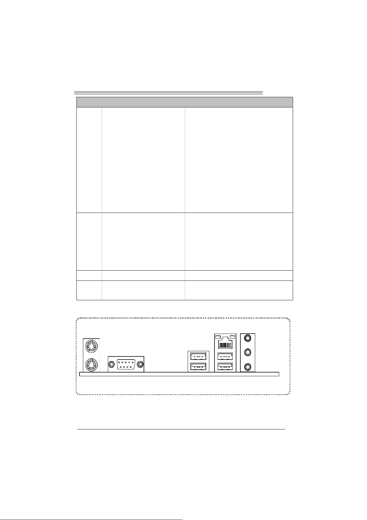
1.4 REAR PANEL CONNECTORS
PS/2
Mouse
PS/2
COM1
Keyboard
Since the audio chip supports High Definition Audio Specification, the function of each audio
jack can be defined by software. The input / output function of each audio jack listed above
represents the default setting. However, when connecting external microphone to the audio
port, please use the Line In (blue) and Mic In (Pink) audio jack.
LAN
Line In/
Surroun d
Line Ou t
Mic In 1/
Bass/ Center
USBX2USBX2
3
Page 6
Motherboard Manual
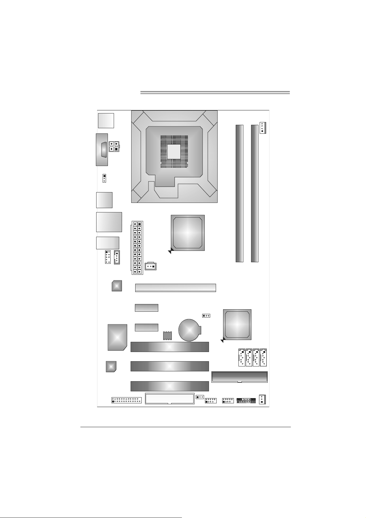
1.5 MOTHERBOARD LAYOUT
JKBMS1
JCOM1
JUSBV1
JUSB1
JRJ45 USB1
JAUDI O2
JAUDIOF1
JATXPWR1
JCDIN1
LAN
JATXPWR2
JSPDIF_OU T1
LGA775
CPU1
Intel
P31/G31
PEX16_1
JCFAN1
DDR2_A1
DDR2_B1
4
Super
CODEC
Note: represents the 1■
I/O
JPRNT1
PEX1_1
PEX1_2
BIOS
FDD1
PCI1
PCI2
PCI3
st
pin.
BAT1
JUSBV2
JCM OS1
JUSB3
Intel
ICH7
JUSB4
SATA1 SATA3
SATA2 SATA4
ID E1
JPANEL1
JSFAN 1
Page 7
CHAPTER 2: HARDWARE INSTALLATION
P31-A7
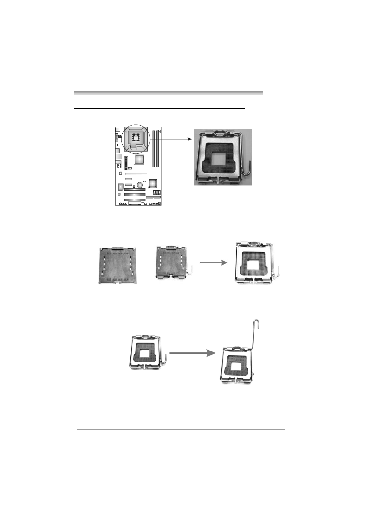
2.1 I
NSTALLING CENTRAL PROCESSING UNIT (CPU)
Special Notice:
Remove Pin Cap before installation, and make good preservation
for future use. When the CPU is removed, cover the Pin Cap on the
empty socket to ensure pin legs won’t be damaged.
Pin Cap
Step 1: Pull the socket locking lever out from the socket and then raise
the lever up to a 90-degree angle.
5
Page 8
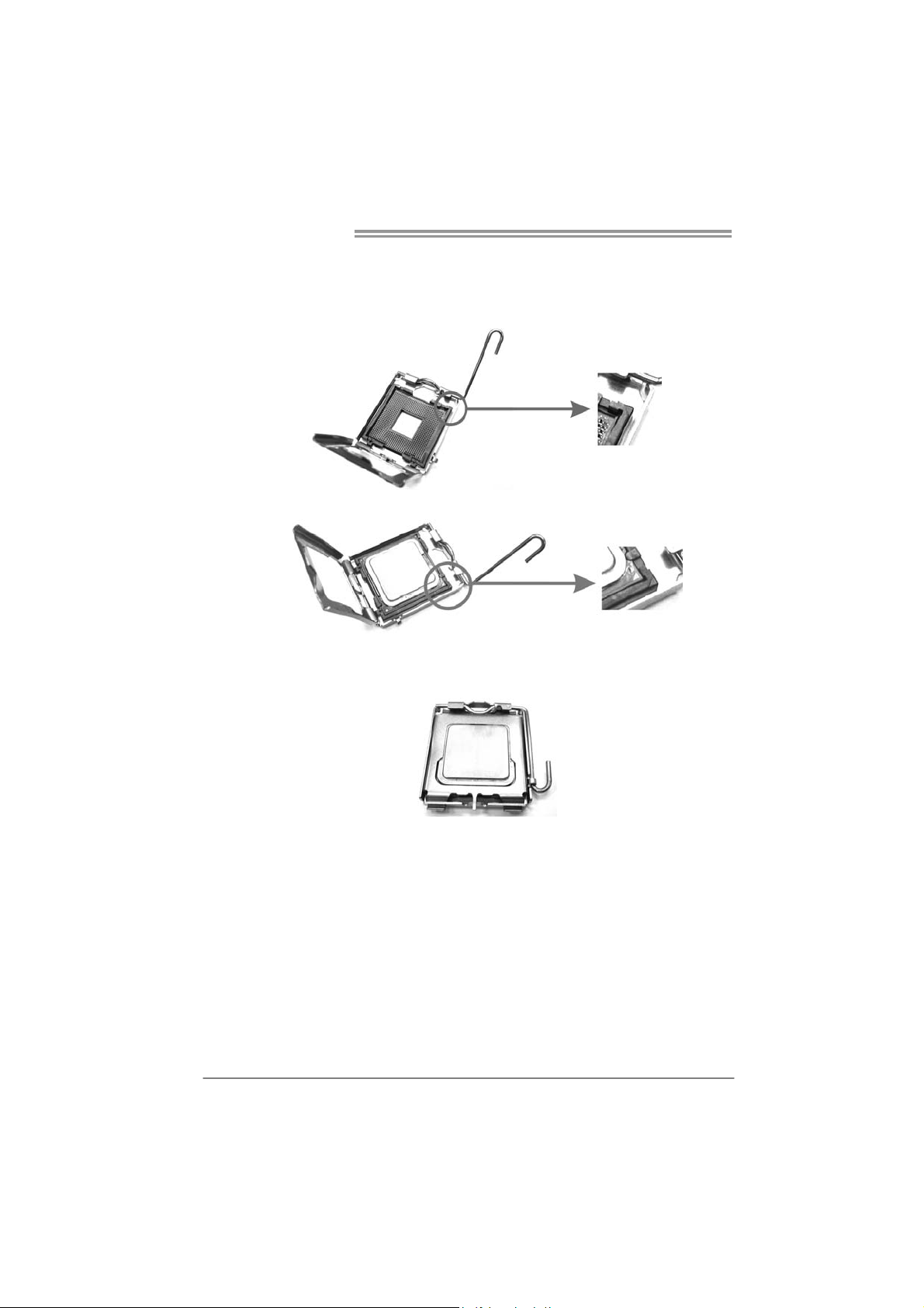
Motherboard Manual
Step 2: Look for the triangular cut edge on socket, and the golden dot on
CPU should point forwards this triangular cut edge. The CPU will
fit only in the correct orientation.
Step 2-1:
Step 2-2:
Step 3: Hold the CPU down firmly, and then lower the lever to locked
position to complete the installation.
Step 4: Put the CPU Fan and heatsink assembly on the CPU and buckle it
on the retention frame. Connect the CPU FAN power cable into
the JCFAN1. This completes the installation.
6
Page 9
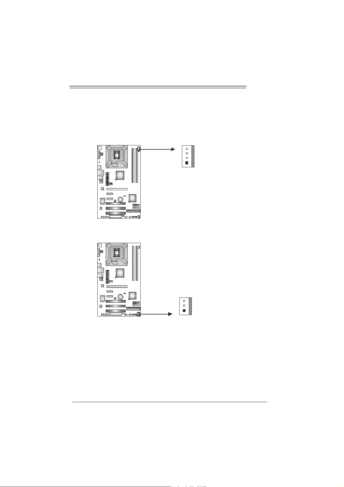
2.2 FAN HEADERS
These fan headers support cooling-fans built in the computer. The fan
cable and connector may be different according to the fan manufact urer.
Connect the fan cable to the connector while matching the black wire to
pin#1.
JCFAN1: CPU Fan Header
4
1
JSFAN1: System Fan Header
JSFAN1
3
Pin
Assignment
1 Ground
2 +12V
3
FAN RPM r at e
sense
4 Smart Fan
Control
Pin
Assignment
1 Ground
2 +12V
3 FAN RPM rate
sense
P31-A7
1
Note:
The JSFAN1 support 3-pin head connector. When connecting with wires onto connectors,
please note that the red wire is the positive and should be connected to pin#2, and the
black wire is Ground a nd should be co nnected to GND.
7
Page 10
Motherboard Manual
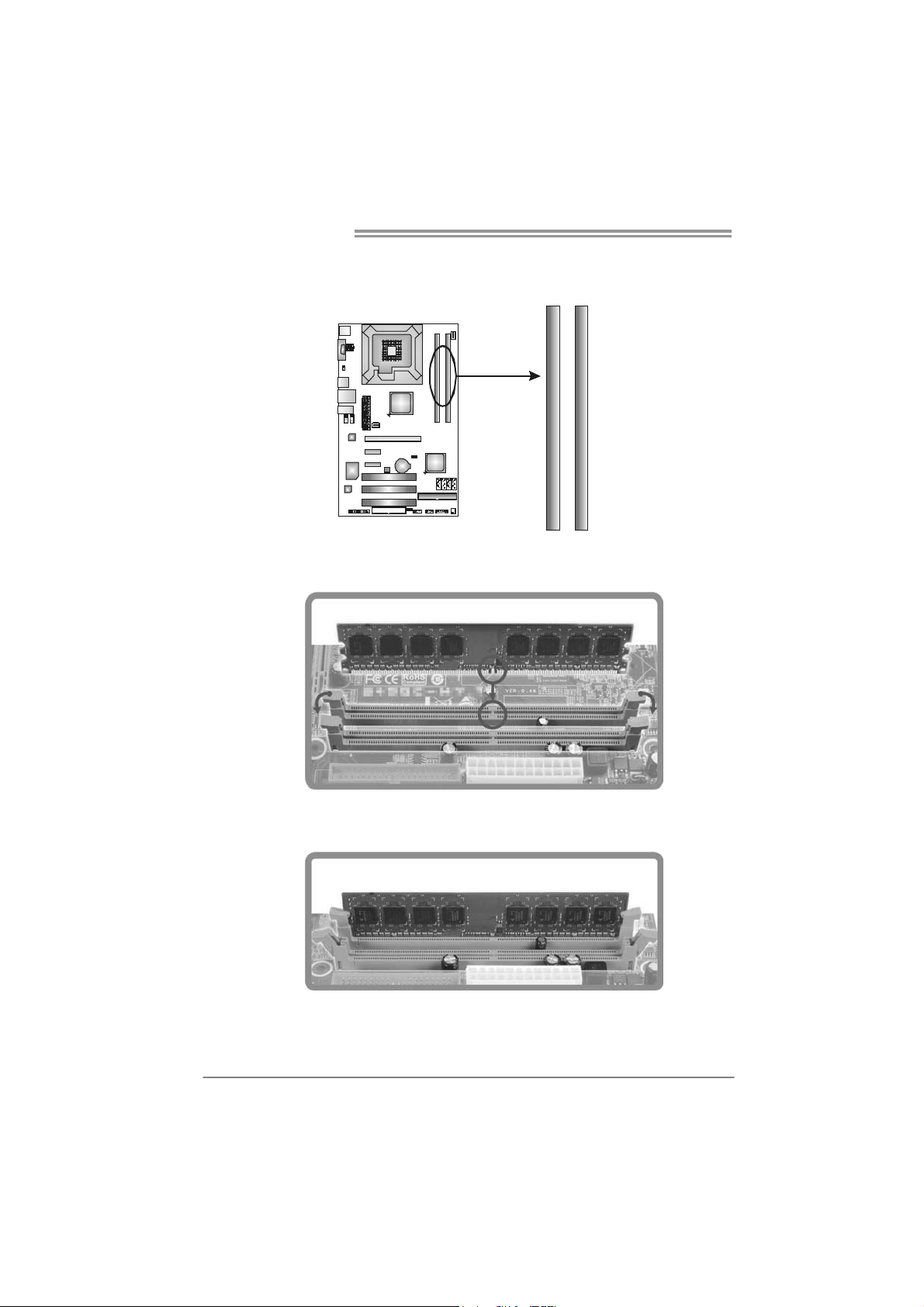
2.3 INSTALLING SYSTEM MEMORY
A. Memory Modules
DDR2 _A1
DDR2 _B1
1. Unlock a DIMM slot by pressing the retaining clips outward. Align a
DIMM on the slot such that the notch on the DIMM matches the
break on the Slot.
2. Insert the DIMM vertically and firmly into the slot until the retaining
chip snap back in place and the DIMM is properly seated.
8
Page 11
B. Memory Capacity
P31-A7
DIMM Socket
Location
DDR2_A1 256MB/512MB/1GB/2GB
DDR2_B1 256MB/512MB/1GB/2GB
DDR Module
Total Mem ory
Size
Max is 4B.
C. Dual Channel Memory installation
To trigger the Dual Channel function of the motherboard, the memory module
must meet the following requirements:
Install memory module of the same density in pairs, shown in the following
table.
Dual Channel Status
Disabled O X
Disabled X O
Enabled O O
DDR2_A1
DDR2_B1
(O means memory installed, X means memory not installed.)
The DRAM bus width of the memory module must be the same (x8 or
x16)
D. FSB Supporting Table
According to the FSB frequency of the installed CPU, the motherboard could
support DDR2 533/667/800 modules. Please refer to the table below to find
out the proper RAM module that fits the FSB of the installed CPU.
FSB of CPU
DDR2 Module
DDR2 533 O X O X
DDR2 667 O O O O
DDR2 800 O O O O
(O means supported, X means not supported.)
FSB 533 FSB 800 FSB 1066 FSB1333
9
Page 12
Motherboard Manual
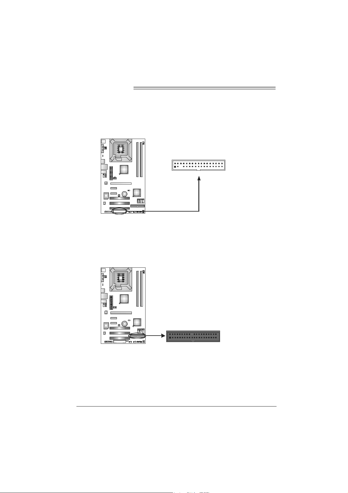
2.4 CONNECTORS AND SLOTS
FDD1: Floppy Disk Connector
The motherboard provides a standard floppy disk connector that supports 360K,
720K, 1.2M, 1.44M and 2.88M floppy disk types. This connector supports the
provided floppy drive ribbon cables.
IDE1: Hard Disk Connector
The motherboard has a 32-bit Enhanced PCI IDE Controller that provides PIO
Mode 0~4, Bus Master, and Ultra DMA 33/66/100 functionality.
The IDE connector can connect a master and a slave drive, so you can connect
up to two hard disk drives.
2
34
331
10
240
1
39
Page 13
PEX16_1: PCI-Express x16 Slot
- PCI-Express 1.0a compliant.
- Maximum theoretical realized bandwidth of 4GB/s simultaneously per
direction, for an aggregate of 8GB/s totally.
PEX1_1/PEX1_2: PCI-Express x1 Slots
- PCI-Express 1.0a compliant.
- Maximum theoretical realized bandwidth of 250MB/s simultaneously per
direction, for an aggregate of 500MB/s totally.
- PCI-Express supports a raw bit-rate of 2.5GB/s on the data pins.
- 2X bandwidth over the traditional PCI architecture.
P31-A7
PEX16_1
PEX1_1
PEX1_2
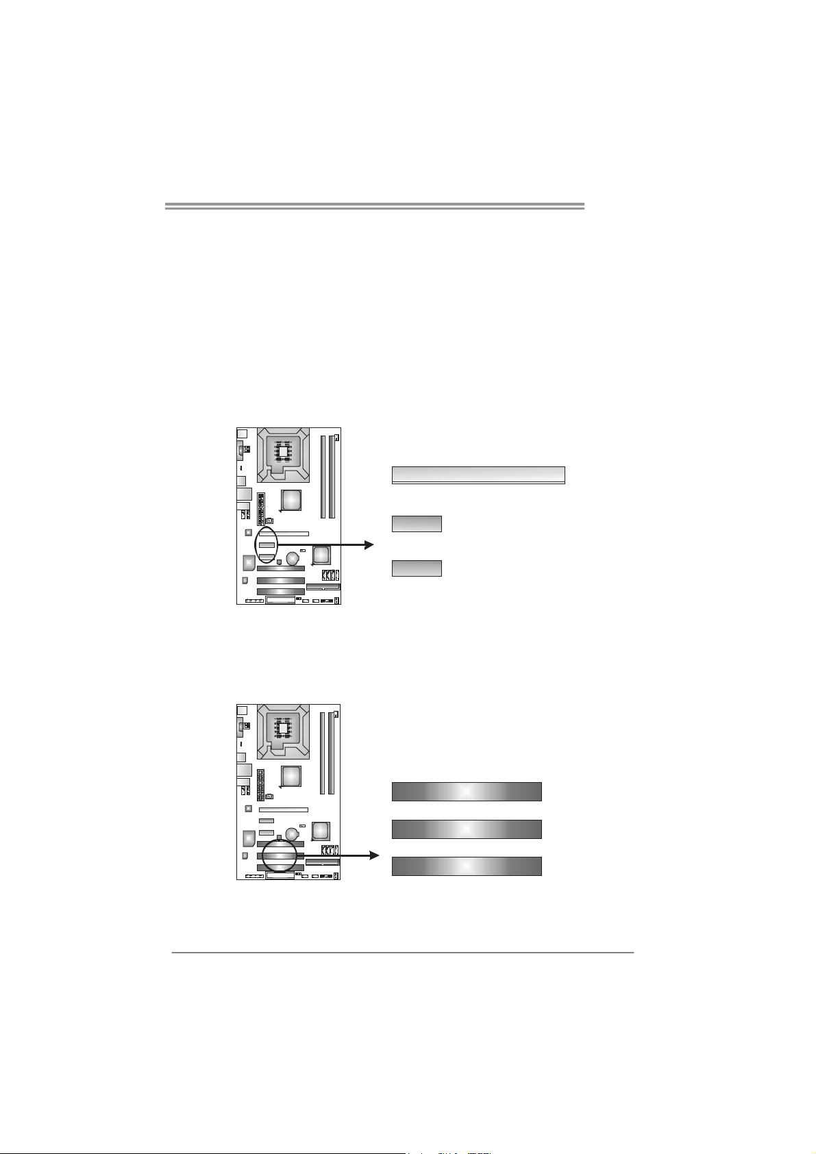
PCI1~PCI3: Peripheral Component Interconnect Slots
This motherboard is equipped with 3 standard PCI slots. PCI stands for
Peripheral Component Interconnect, and it is a bus standard for expansion
cards. This PCI slot is designated as 32 bits.
PCI1
PCI2
PCI3
11
Page 14

Motherboard Manual
CHAPTER 3: HEADERS & JUMPERS SETUP
3.1 H
OW TO SETUP JUMPERS
The illustration shows how to set up jumpers. When the jumper cap is
placed on pins, the jumper is “close”, if not, that means the jumper is
“open”.
Pin opened Pin closed Pin1-2 closed
3.2 D
JPANEL1: Front Panel Header
ETAIL SETTINGS
This 16-pin connector includes Power-on, Reset, HDD LED, Power LED, and
speaker connection. It allows user to connect the PC case’s front panel switch
functions.
PWR_LED
On/Off
-
SPK
++
+
HL ED
-
16
8
RS T
9
1
12
Pin Assignment Function Pin Assignment Function
1 +5V 9 N/A
2 N/A 10 N/A
3 N/ A 11 N/ A N/A
4 Speaker
5 HDD LED (+) 13 Power LED (+)
6 HDD LED (-)
7 Ground 15 Power button
8 Reset control
Speaker
Connector
Hard drive
LED
Reset button
12 Power LED (+)
14 Power LED (-)
16 Ground
N/A
Power LED
Power-on button
Page 15

JATXPWR2: AT X P ower Source Connector
This connector allows user to connect 24-pin power connector on the ATX
power supply.
P31-A7
13
24
Pin Assignment Pin Assignment
1
12
13 +3.3V 1 +3.3V
14 -12V 2 +3.3V
15 Ground 3 Gro und
16 PS_ON 4 +5V
17 Ground 5 Gro und
18 Ground 6 +5V
19 Ground 7 Gro und
20 NC 8 PW_OK
21 +5V 9 Standby Voltage+5V
22 +5V 10 +12V
23 +5V 11 +12V
24 Ground 12 +3.3V
JATXPWR1: AT X P ower Source Connector
By connecting this connector, it will provide +12V to CPU power circuit.
1234
Pin
Assignment
1 +12V
2 +12V
3 Ground
4 Ground
13
Page 16

Motherboard Manual
JUSB3/JUSB4: Headers for USB 2.0 Ports at Front Panel
This header allows user to connect additional USB cable on the PC front panel,
and also can be connected with internal USB devices, like USB card reader.
JUSB3 JUSB4
2
10
1
9
JAUDIOF1: Front Panel Audio Header
This header allows user to connect the front audio output cable with the PC front
panel. This header allows only HD audio front panel connector; AC’97 connector
is not acceptable.
12
910
Assignment
Pin
1 +5V (fused)
2 +5V (fused)
3 USB4 USB5 USB+
6 USB+
7 Ground
8 Ground
9 Key
10 NC
Pin Assignment
1 Mic Left in
2 Ground
3 Mic Right in
4 GPIO
5 Right line in
6 Jack Sense
7 Front Sense
8 Key
9 Left line in
10 Jack Sense
JCDIN1: CD-ROM Audio-in Connector
This connector allows user to connect the audio source from the variaty devices,
like CD-ROM, DVD-ROM, PCI sound card, PCI TV turner card etc..
14
Assignment
Pin
1
4
1 Left Channel Input
2 Ground
3 Ground
4 Right Channel Input
Page 17

P31-A7
JCMOS1: Clear CMOS Header
By placing the jumper on pin2-3, it allows user to restore the BIOS safe setting
and the CMOS data, please carefully follow the procedures to avoid damaging
the motherboard.
13
13
13
Pin 1-2 Close:
Normal Operation (default).
Pin 2-3 Close:
Clear CMOS data.
※ Clear CMOS Procedures:
1. Remove AC power line.
2. Set the jumper to “Pin 2-3 close”.
3. Wait for five seconds.
4. Set the jumper to “Pin 1-2 close”.
5. Power on the AC.
6. Reset your desired password or clear the CMOS data.
SATA1~SATA4: Serial ATA Connectors
The motherboard has a PCI to SATA Controller with 4 channels SATA interface,
it satisfies the SATA 2.0 spec and with transfer rate of 3.0Gb/s.
Pin
Assignment
1 Ground
2 TX+
SAT A 1
SAT A 2
SAT A 3
SAT A 4
1
4
7
3 TX4 Ground
5 RX6 RX+
7 Ground
15
Page 18

Motherboard Manual
JSPDIF_OUT1: Digital Audio-out Connector (Optional)
This connector allows user to connect the PCI bracket SPDIF output header.
13
JUSBV1/JUSBV2: Power Source Headers for USB Ports
Pin 1-2 Close:
JUSBV1: +5V for USB ports at JUSB1/JRJ45USB1.
JUSBV2: +5V for USB ports at front panel (JUSB3/JUSB4).
Pin 2-3 Close:
JUSBV1: USB ports at JUSB1/JRJ45USB1 are powered by +5V standby
voltage.
JUSBV2: USB ports at front panel (JUSB3/JUSB4) are powered by +5V
standby voltage.
Pin
Assignment
1 +5V
2 SPDIF_OUT
3 Ground
16
JUSBV1
1
3
JUSBV2
13
1
3
Pin 1-2 close
1
3
Pin 2-3 close
Note:
In order to support this function “Power-On system via USB device,” “JUSBV1/ JUSBV2”
jumper cap should be placed on Pin 2-3 individually.
Page 19

JPRNT1: Printer Port Connector
This header allows you to connector printer on the PC.
2
P31-A7
1
25
Pin Assignment Pin Assignment
1 -Strobe 14 Ground
2 -ALF 15 Data 6
3 Data 0 16 Ground
4 -Error 17 Data 7
5 Data 1 18 Ground
6 -Init 19 -ACK
7 Data 2 20 Ground
8 -Scltin 21 Busy
9 Data 3 22 Ground
10 Ground 23 PE
11 Data 4 24 Ground
12 Ground 25 SCLT
13 Data 5 26 Key
17
Page 20

Motherboard Manual
CHAPTER 4: USEFUL HELP
4.1 D
RIVER INSTALLATION NOTE
After you installed your operating system, please insert the Fully Setup
Driver CD into your optical drive and install the driver for better system
performance.
You will see the following window after you insert the CD
The setup guide will auto detect your motherboard and operating system.
Note:
If this window didn’t show up after you insert the Driver CD, please use file browser to
locate and execute the file SETUP.EXE under your optical drive.
A. Driver Installation
To install the driver, please click on the Driver icon. The setup guide will
list the compatible driver for your motherboard and operating system.
Click on each device driver to launch the installation program.
B. Software Installation
To install the software, please click on the Software icon. The setup guide
will list the software available for your system, click on each software title
to launch the installation program.
C. Manual
Aside from the paperback manual, we also provide manual in the Driver
CD. Click on the Manual icon to browse for available manual.
Note:
You will need Acrobat Reader to open the manual file. Please download the latest version
of Acrobat Reader so ftware from
http://www.adobe.com/products/acrobat/readstep2.html
18
Page 21

4.2 AWARD BIOS BEEP CODE
Beep Sound Meaning
One long beep followed by two short
beeps
High-low siren sound CPU overheated
One Short beep when system boot-up No error found during POST
Long beeps every other second No DRAM detected or install
Video card not found or video card
memory bad
System will shut down automatically
P31-A7
4.3 E
XTRA INFORMATION
CPU Overheated
If the system shutdown automatically after power on system for
seconds, that means the CPU protection function has been activated.
When the CPU is over heated, the motherboard will shutdown
automatically to avoid a damage of the CPU, and the system may not
power on again.
In this case, please double check:
1. The CPU cooler surface is placed evenly with the CPU surface.
2. CPU fan is rotated normally.
3. CPU fan speed is fulfilling with the CPU speed.
After confirmed, please follow steps below to relief the CPU protection
function.
1. Remove the power cord from power supply for seconds.
2. Wait for seconds.
3. Plug in the power cord and boot up the system.
Or you can:
1. Clear the CMOS data.
(See “Close CMOS Header: JCMOS1” section)
2. Wait for seconds.
3. Power on the system again.
19
Page 22

Motherboard Manual
4.4 TROUBLESHOOTING
Probable Solution
1. No power to the system at all
Power light don’t illuminate, fan
inside power supply does not turn
on.
2. Indicator light on keyboard does
not turn on.
System inoperative. Keyboard lights
are on, power indicator lights are lit,
and hard drive is spinning.
System does not boot from hard disk
drive, can be booted from optical drive.
System only boots from optical drive.
Hard disk can be read and applications
can be used but booting from hard disk
is impossible.
Screen message says “Invalid
Configuration” or “CMOS Failure.”
Cannot boot system after installing
second hard drive.
1. Make sure power cable is
securely plugged in.
2. Replace cable.
3. Contact technical support.
Using even pressure on both ends of
the DIMM, press down firmly until the
module snaps into place.
1. Check cable running from disk to
disk controller board. Make sure
both ends are securely plugged
in; check the drive type in the
standard CMOS setup.
2. Backing up the hard drive is
extremely important. All hard
disks are capable of breaking
down at any time.
1. Back up data and applications
files.
2. Reformat the hard drive.
Re-install applications and data
using backup disks.
Review system’s equipment. Make sure
correct information is in setup.
1. Set master/slave jumpers
correctly.
2. Run SETUP program and select
correct drive types. Call the drive
manufacturers for compatibility
with other drives.
20
Page 23

P31-A7
This page is intentionally left blank.
21
Page 24

Motherboard Manual
APPENDENCIES: SPEC IN OTHER LANGUAGE
G
ERMAN
Sp ezif ika tio nen
LGA 775
CPU
FSB 533 / 800 / 1066 / 1333 MHz
Chipsatz
Super E/A
Arbeitsspeich
er
IDE Integ r iert er IDE-C o ntr o ller
SATA Integrierter Serial ATA-Controller
LAN Realtek RTL 8111C / RTL 8101E(optional)
HD
Audio-Unters
tützung
Steckplätz e
Intel Core2Duo / Core2Quad / Celeron 4xx
/ Pentium 4 / Pent ium D / Celeron D
Prozessoren
Intel P31 / G31
Int e l ICH7
ITE 8712F
Biet et die h äuf ig v erwend eten a lten S up er
E/A-Funktionen.
Low Pin Count-Schnittstelle
DDR2 DIMM-Steckplätze x 2
Jeder DIMM unterstützt 256MB / 512MB /
1GB / 2GB DDR2.
Max. 4GB Arbeitsspeicher
ALC662
PCI-Steckp latz x 3
PCI Express x16 Steckplatz x1
PCI Express x 1-Steckplatz x2
Unterstützt Hyper-Threading / Execute Disable Bit /
Enhanced Inte l SpeedStep® / Int el Arch itecture-64 /
Extended Memory 64 Technology / Virtualization
Technology
Umgebungskontrolle,
Hardware-Überwachung
Lüfterdrehzahl-Controller/-Überwachung
"Smart Guardian"-Funktion von ITE
Dual-Kanal DDR2 Speichermodul
Unterstützt DDR2 800/667
Unterstützt DDR2 533 (w. FSB 533/1066 CPU)
registrierte DIMMs. ECC DIMMs werden nicht
unterstützt.
Ultra DMA 33 / 66 / 100 Bus Master- Modus
Unterstützt PIO-Modus 0~4,
Datentransferrate b is zu 3.0Gb /s
Konform mit der SATA-Spezifikation Version 2.0.
10 / 100 / 1000 Mb/s Auto-Negotiation
(Gigabit-Bandbreite nur beim RTL 8111C)
Halb-/ Vollduplex-Funktion
Unterstützt High-Definition Audio
5.1-Kanal-Audioausgabe
22
Page 25

Sp ezif ika tio nen
Diskettenlaufwerkanschluss x1 Jeder Anschluss unterstützt 2 Diskettenlaufwerke
Druckeranschluss Anschluss x1 Jeder Anschluss unterstützt 1 Druckeranschluss
IDE-Anschluss x1 Jeder Anschluss unterstützt 2 IDE-Laufwerke
SATA-Anschluss x4 Jeder Anschluss unterstützt 1 SATA-Laufwerk
Fronttafelanschluss x1 Unterstützt die Fronttafelfunktionen
Front-Audioanschluss x1 Unterstützt die Fronttafel-Audioanschlussfunktion
CD-IN-Anschluss x1 Unterstützt die CD Audio-In-Funktion
Onboard-Ans
chluss
Rückseiten-E
/A
Platinengröße 190 mm (B) X 305 mm (L)
OS-Unterstüt
zung
S/PDIF- Ausgangsanschluss x1 Unterstützt die digitale Audioausgabefunktion
CPU-Lüfter-Sockel x1
System-Lüfter-Sockel x1 System-Lüfter-Stromversorgungsanschluss
"CMOS löschen"-S ockel x1
USB-Anschluss x2
Stromanschluss (24-polig) x1
St romansch luss (4-po lig ) x1
PS/2-Tastatur x1
PS/2-Maus x1
Serieller Anschluss x1
LAN-Anschluss x1
USB-Anschluss x4
Audioanschluss x3
Windows 2000 / XP / VISTA
P31-A7
CPU-Lüfterstromversorgungsanschluss (mit Smart
Fan -F un ktio n)
Jeder Anschluss unterstützt 2
Fronttafel-USB-Anschlüsse
Biostar behält sich das Recht vor, ohne Ankündigung
die Unterstützung für ein Betriebssystem
hinzuzufügen oder zu entfernen.
23
Page 26

Motherboard Manual
FRENCH
LGA 775
UC
Bus frontal 533 / 800 / 1066 / 1333 MHz
Chipset
Super E/S
Mémoire
principale
IDE Contrôleur IDE intégré
SATA
LAN Realtek RTL 8111C / RTL 8101E(optional)
Prise en
charg e
aud io HD
Processeurs Intel Core2Duo / Core2Quad
/ Celeron 4x x / Pentium 4 / Pent ium D /
Celeron D
Intel P31 / G31
Int e l ICH7
ITE 8712F
Fournit la fonctionnalité de Super E/S
patrimoniales la plus utilisée.
Int e rfa ce à faib le co mpt e d e b roches
Fentes DDR2 DIMM x 2
Chaque D IMM prend en c harge des DDR2
de 256Mo / 512Mo / 1Go / 2Go
Capacit é mé mo ir e max ima le de 4G o
Contrô leur Serial ATA int é gr é
ALC662
Fente PCI x3
Fente PC I Expres s x16 x1 Fentes
Fente PCI Express x1 x2
SPEC
Prend en charge les technologies Hyper-Threading /
d'ex écut ion de b it de désact ivat ion / Intel SpeedStep®
opt imisée/ d ' arch itectur e Int e l 64 / de mémo ire
étendue 64 / de virtualisation
Initiatives de contrôle environnementales,
Mon iteur d e mat ériel
Contrôleur /moniteur de vitesse de ventilateur
Fonction "Gardien intelligent" de l'ITE
Modu le d e mémo ire DDR2 à mode à double vo ie
Prend en charge la DDR2 800/667
Prend en charge la DDR2 533 (w. FSB 533/1066 CPU)
Les DIMM à registres et DIMM avec code correcteurs
d'erreurs ne sont pas prises en charge
Mode principale de Bus Ultra DMA 33 / 66 / 100
Prend en charge le mode PIO 0~4,
Taux de transfert jusqu'à 3.0Go/s.
Co nfo rme à la spécif icat ion SATA Vers io n 2.0
10 / 100 / 1000 Mb/s négociation automatique (La
bande passante Gigabit est pour le RTL 8111C
uniquement)
Half / Full duplex capability
Prise en charg e de l'aud io haut e déf inition
Sortie aud io à 5 .1 vo ies
24
Page 27

Connecteur de disquette x1
Connecteur de Port d'imprimante x1 Chaque connector prend en charge 1 Port d'imp rimante
Connecteur IDE x1
Connecteur SATA x4
Connecteur du panneau avant x1 Prend en charge les équipements du panneau avant
Connecteur Audio du panneau avant x1 Prend en charge la fonct ion audio du panneau avant
Connecteur
embarqu é
E/S du
panneau
arrière
Dimensions
de la carte
Support SE W indows 2000 / XP / VISTA
Connecteur d'entrée CD x1 Prend en charge la fonct ion d'entr ée aud io de CD
Connecteur de sortie S/PDIF x1 Prend en charge la fonction de sortie audio numérique
Embase de ventilateur UC x1
Embase de ventilateur système x1 Alimentation électrique du ventilateur système
Embase d'effacement CMOS x1
Connecteur USB x2
Connecteur d' aliment at ion x1
(24 broches)
Connecteur d' aliment at ion x 1
(4 broch es)
Clavier PS/2 x1
Souris PS/2 x1
Port série x1
Port LAN x1
Port USB x4
Fiche aud io x3
190 mm (l) X 305 mm (H)
P31-A7
SPEC
Chaque co nnector prend en ch arg e 2 lecteurs de
disquettes
Chaque connecteur prend en ch arg e 2 périp hér iqu es
IDE
Chaque connecteur prend en ch arg e 1 périp hér iqu e
SATA
Alimentation électrique du ventilateur UC (avec
fonction de ventilateur intelligent)
Chaque connecteur prend en charge 2 ports USB de
panneau avant
Biostar se réserve le droit d'ajouter ou de supprimer le
support de SE avec ou sans préavis.
25
Page 28

Motherboard Manual
ITALIAN
SPECIFICA
LGA 775
CPU
FS B 533 / 800 / 1066 / 1333 MHz
Chipset
Super I/O
Memor ia
principale
IDE Con t roller IDE integ rato
SATA Controller Serial ATA integrato
Processore Intel Core2Duo /
Core2Quad / Celeron 4xx / Pentium 4
/ Pentium D / Celeron D
Intel P31 / G31
Int e l ICH7
ITE 8712F
Fo rnis ce le funzional it à legacy S uper
I/O usate più comunemente.
Interfaccia LPC (Low Pin Count)
Alloggi DIMM DDR2 x 2
Ciascun DIMM supporta DDR2 256MB
/ 512MB / 1GB / 2GB
Capacità massima della memoria 4GB
Supporto di Hyper-Threading / Execute Disable
Bit / Enhanced Inte l SpeedStep® / A rchitettura
Intel 64 / Tecnologia Extended Memory 64 /
Tecnologia Virtualization
Funzioni di controllo dell’ambiente:
Monitoraggio hardware
Co ntroller / Monit o raggio ve lo cità ventol ina
Funzione "Smart Guardian" di ITE
Modulo di memoria DDR2 a canale doppio
Supporto di DDR2 800/667
Supporto di DDR2 533 (w. FSB 533/1066 CPU)
DIMM registrati e DIMM ECC non sono supportati
Modalità Bus Master Ultra DMA 33 / 66 / 100
Supporto modalità PIO Mode 0-4
Velocità di trasferimento dei dati fino a 3.0Gb/s.
Co mp at ibile specifiche SATA Ver s ione 2.0.
LA N Realtek RTL 8111C / RTL 8101E (optional)
Supporto
ALC662
audio HD
Allo g gio PC I x3
Alloggio PCI Express x16 x1 Allo g gi
Alloggio PCI Express x1 x2
26
Negoziazione automatica 10 / 100 / 1000 Mb/s
(la larghezza di banda Gigabit è solo per RTL
8111C)
Capacità Half / Full Dup lex
Supporto audio High-Definition (HD)
Uscita audio 5.1 canali
Page 29

Connettori
su scheda
P31-A7
SPECIFICA
Connettore floppy x1 Ciascun connettore supporta 2 unità Floppy
Connettore Porta stampante x1 Ciascun connettore supporta 1 Porta stampante
Connettore IDE x1 Ciascun connettore supporta 2 unità IDE
Connettore SATA x4 Ciascun connettore supporta 1 unità SATA
Co nnettore p an nello front ale x 1 S uppor ta i s er viz i del pann e llo f ro n tale
Connettore audio frontale x1 Supporta la funzione audio pannello frontale
Connettore CD-in x1 Supporta la funzione input audio CD
Connettore output SPDIF x1 Supporta la funzione d’output audio digitale
Alimentazione ventolina CPU (con funzione Smart
Co llet t o re ven tolina CPU x 1
Fan)
Co llet t o re ven tolina sistema x1 Aliment az io ne vent olina d i sistema
Co llet t o re can ce l laz ione CMOS x1
Ciascun connettore supporta 2 porte USB
Connettore USB x2
pannello frontale
I/O
pannello
posteriore
Dimension
i scheda
Sistemi
operat ivi
supportati
Connettore alimentazione x1
(24 pin)
Connettore alimentazione x1
(4 pin)
Tas t iera P S / 2 x 1
Mou s e PS /2 x1
Porta seriale x1
Porta LA N x1
Porta USB x 4
Connettore audio x3
190 mm (larghezza) x 305 mm
(altez za)
Windows 2000 / XP / VISTA
Biostar si riserva il diritto di aggiungere o
rimuovere il supporto di qualsiasi sistema
operativo senza preavviso.
27
Page 30

Motherboard Manual
SPANISH
Especificación
LGA 775
CPU
FSB 533 / 800 / 1066 / 1333 MHz
Conjunto de
chips
Súper E/S
Memoria
principal
IDE Controlador IDE integrado
SATA Controlador ATA Serie Integrado
Procesador Intel Core2Duo / Core2Quad /
Celeron 4xx / Pentium 4 / Pentium D /
Celeron D
Intel P31 / G31
Int e l ICH7
ITE 8712F
Le ofrece las funcionalidades heredadas de
us o más comú n Súper E /S.
Interfaz de cuenta Low Pin
Ranuras DIMM DDR2 x 2
Cada DIMM admite DDR de 256MB /
512MB / 1GB / 2GB
Capacidad máxima de memoria de 4GB
Admite Hyper-Threading / Bit de deshabilitación de
ejecución / Intel SpeedStep® Mejo rado / Inte l
Architecture-64 / Tecnología Extended Memory 64 /
Tecnología de virtualización
In iciat iv as d e co n tro l d e ent o rn o ,
Monitor hardware
Controlador/monitor de velocidad de ventilador
Función "Guardia inteligente" de ITE
Módulo de memoria DDR2 de canal Doble
Admite DDR2 de 800/667
Admite DDR2 de 533 (w. FSB 533/1066 CPU)
No admite DIMM registrados o DIMM compatibles con
ECC
Modo bus maestro Ultra DMA 33 / 66 / 100
Soporte los Modos PIO 0~4,
Tasas de transferencia de hasta 3.0 Gb/s.
Co mp at ible con la ve rsión SATA 2. 0.
Red Local Realtek RTL 8111C / RTL 8101E (opcional)
Soporte de
ALC662
sonido HD
Ranura PCI X3
Ranura PCI Express x16 X1 Ranuras
Ranura PCI express x 1 X2
28
Negociación de 10 / 100 / 1000 Mb/s (el ancho de
banda Gigabit es únicamente para 8111C)
Funciones Half / Full dúplex
Soporte de sonido de Alta Definición
Salida de sonido de 5.1 canales
Page 31

Conectores
en p laca
P31-A7
Especificación
Conector disco flexible X1 Cada conector soporta 2 unid ades de disco flexible
Conector Puerto de impresora X1 Cada conector soporta 1 Puerto de impresora
Conector IDE X1 Cada conector soporta 2 dispositivos IDE
Conector SATA X4 Cada conector soporta 1 dispositivos SATA
Co nect o r de p anel f ro n tal X1 So p ort a in s talacion es en el p an el f ron tal
Conector de sonido frontal X1 Soporta funciones de sonido en el panel frontal
Conector de entrada de CD X1 Soporta función de entrada de sonido de CD
Conector de salida S/PDIF X1 Soporta función d e salida de sonido digital
Cabecera de ventilador de CPU X1 Fuente de alimentación de ventilador de CPU (con
función Smart Fan)
Cabecera de ventilador de sistema X1 Fuente de alimentación de ventilador de sistema
Cabecera de borrado de CMOS X1
Conector USB X2 Cada conector so porta 2 puertos USB frontales
Conector de alimentación X1
(24 patillas)
Conector de alimentación X1
(4 patillas)
Tec lad o P S /2 X 1
Panel
trasero de
E/S
Ta mañ o d e
la placa
Soporte de
sistema
operativo
Ratón PS/2 X1
Puert o ser ie X1
Puerto de red local X1
Puert o USB X4
Conector de sonido X3
190 mm. (A) X 305 Mm. (H)
Windows 2000 / XP / VISTA
Biostar se reserva el derecho de añadir o retirar el
soporte de cualquier SO con o sin aviso previo.
29
Page 32

Motherboard Manual
PORTUGUESE
ESPECIFICAÇÕES
LGA 775
CPU
FSB 533 / 800 / 1066 / 1333 MHz
Chipset
Especificaçã
o Super I/O
Memória
principal
IDE Controlador IDE integrado
Processador Intel Core2Duo /
Core2Quad / Celeron 4xx / Pentium 4 /
Pentium D / Celeron D
Intel P31 / G31
Int e l ICH7
ITE 8712F
Proporciona as funcionalidades mais
utilizadas em termos da especificação
Super I/O.
Interface LPC (Low Pin Count).
Ranhuras DIMM DDR2 x 2
Cada módulo DIMM suporta uma
memória DDR2 de 256 MB / 512 MB / 1GB
/ 2GB
Capacidad e máx ima de me mória:4 GB
Sup orta as tecno log ias Hyper-Threading / Execut e
Disab le Bit / Enhanced Intel SpeedStep® / Int el
Arquitecture -64 / Extended Memory 64 / Virtualization
In iciat iv as p ar a cont ro lo do a mbient e
Monitorização do hardware
Controlador/Monitor da velocidade da ventoinha
Função "S mart Gu ard ian" da ITE
Módulo de memória DDR2 de canal duplo
Suporta módulos DDR2 800/667
Suporta módulos DDR2 533 (w. FSB 533/1066 C PU)
Os módulos DIMM registados e os DIMM ECC não são
suportados
Modo Bus master Ultra DMA 33 / 66 / 100
Suporta o modo PIO 0~4,
SATA Controlador Serial ATA integrado
LAN Realtek RTL 8111C / RTL 8101E(opcional)
Suporte
para áudio
de alta
definição
ALC662
30
Velocidades de transmissão de dados até 3.0 Gb/s.
Compat ibilidade co m a es pe cificação SATA versão 2.0.
Auto negociação de 10 / 100 / 1000 Mb/s (a largura de
banda Gigab it refere- se apenas à es pe cificação RTL
8111C)
Capacidade semi/full-duplex
Suporta a especificação High-Definition Audio
Saída de áudio de 5.1 canais
Page 33

Ranhuras
Conectores
na placa
Entradas/S
aídas no
painel
traseiro
Tamanho
da placa
Sistemas
operativos
suportados
P31-A7
ESPECIFICAÇÕES
Ranhura PCI x3
Ranhura PCI Express x16 x1
Ranhura PCI Express x 1 x2
Conector da unidade de disquetes x1 Cada conector suporta 2 unidades de d isquetes
Conector da para impressora x1 Cada conector suporta 1 Porta para impressora
Conector IDE x1 Cada conector suporta 2 dispositivos IDE
Conector SATA x4 Cada conector suporta 1 disposit ivo SATA
Conector do painel frontal x1 Para suporte de várias funções no painel frontal
Conector d e áud io frontal x1 Suporta a fun ção de áud io no p ainel frontal
Conector para entrada de CDs x 1 Suporta a entr ada d e áud io a p artir de CDs
Conector de saíd a S/PD IF x1 Suporta a saída de áud io d ig ital
Conector da ventoinha da CPU x1
Conector da ventoinha do s istema x1 Alimentação da ventoinha do sistema
Conector para limpeza do CMOS x1
Conector USB x2 Cada conector suporta 2 portas USB no painel frontal
Conector de alimentação x1
(24 pinos)
Conector de alimentação x1
(4 p inos)
Tec lad o P S /2 x 1
Rato PS/2 x1
Porta série x1
Porta LA N x1
Porta USB x4
Tomada de áudio x3
190 mm (L) X 305 mm (A)
Windows 2000 / XP / VISTA
Aliment ação da vento inh a da CP U (co m a fun ção S mart
Fan )
A Biostar reserva-se o direito de adicionar ou remover
suporte para qualquer sistema operativo com ou sem
av iso pr év io .
31
Page 34

Motherboard Manual
POLISH
SPEC
LGA 775
Procesor
FSB 533 / 800 / 1066 / 1333 MHz
Chipset
Pamięć
główna
Super I/O
IDE Zintegrowany kontroler IDE
Procesor Intel Core2Duo / Core2Quad /
Celeron 4xx / Pentium 4 / Pentium D /
Celeron D
Intel P31 / G31
Int e l ICH7
Gniazda DDR2 DIMM x 2
Każde gniazdo DIMM obs ługuje moduły
256MB / 512MB / 1GB / 2GB
Maks. wielkość pamięci 4GB
ITE 8712F
Zapewnia najbardziej powszechne funkcje
Super I/O.
Interfejs Low Pin Count
Obsługa Hyper-Threading / Execute Disable Bit /
Enhanced Inte l SpeedStep® / Int e l Architecture-64 /
Extended Memory 64 Technology / Virtualization
Technology
Mod uł pamięci DDR2 z trybem podwójnego kanału
Obsługa DDR2 800/667
Obsługa DDR2 533 (w. FSB 533/1066 CPU)
Brak obsług i Regist ered D IMM oraz ECC D IMM
Funkcje kontroli warunków pracy,
Mon itor H /W
Kontroler/Monitor prędkości went ylatora
Funkcja ITE "Smart Guard ian"
Ultra DMA 33 / 66 / 100 Tryb Bus Master
obsługa PIO tryb 0~4,
SATA Zintegrowany kontroler Serial ATA
LAN Realtek RTL 8111C / RTL 8101E (opcja)
Obsługa
aud io HD
Gniazda
ALC662
Gniazdo PCI x3
Gniazdo PCI Express x16 x1
Gniazdo PCI Express x 1 x2
32
Transfer danych do 3.0 Gb/s.
Zgodność ze specyfikacją SATA w wersji 2.0.
10 / 100 / 1000 Mb/s z automatyczną negocjacją
szybkości (Pasmo gigabitowe wyłącznie d la RTL 8111C)
Działanie w trybie połowicznego / pełnego dupleksu
Obsługa H igh- D ef inition Aud io
5.1 kanałowe wyjście audio
Page 35

Złącza
wbud owan e
P31-A7
SPEC
Złącze napędu dyskietek x1 Każde złącze obs ługuje 2 napędy dyskietek
Złącze Port drukarki x1 Każde złącze obs ługuje 1 Port drukarki
Złącze IDE x1 Każde złącze obs ługuje 2 urządzenia IDE
Złącze SATA x4 Każde złącze obs ługuje 1 urządzenie SATA
Złącze panela przedniego x1 Obsługa elementów panela przedniego
Przedn ie złącze audio x1 Obsługa funkcji audio na panelu przednim
Złącze wejścia CD x1 Obsługa funkcji wejścia audio CD
Złącze wyjścia S/PDIF x1 Obsługa funkcji cyfrowego wyjścia audio
Złącze głó wkow e went ylato ra
Zasilanie wentylatora procesora (z funkcją Smart Fan)
procesora x1
Złącze głó wkow e went ylato ra
Zasilanie wentylatora systemowego
systemowego x1
Złącze głó wkowe kasowan ia CMOS x 1
Każde złącze obs ługuje 2 porty USB na panelu
Złącze USB x2
przednim
Złącze zasilania (24 pinowe) x1
Złącze zas ilania (4 p ino we) x1
Back Panel
I/O
Wymiary
płyty
Obsluga
systemu
operacyjne
go
Klawiatura PS/2 x1
Mys z PS /2 x1
Port szeregowy x 1
Port LAN x1
Port USB x4
Gniazdo audio x3
190 mm (S) X 305 mm (W)
Windows 2000 / XP / VISTA
Biostar zastrzega sobie prawo dodawania lub
odwoływ ania obsług i dowo ln ego sys t emu
operacyjnego b ez powiado mienia.
33
Page 36

Motherboard Manual
/
RUSSIAN
CPU
(центральн
ый
процессор)
FSB 533 / 800 / 1066 / 1333 МГц
Набо р
микросхем
Основная
память
Super I/O
IDE
SATA
Локальна я
сеть
Звуко вая
поддержка
жестког о
диска
Слоты
LGA 775
Процессор Intel Core2Duo / Core2Quad
Celeron 4xx / Pentium 4 / Pentium D /
Celeron D
Intel P31 / G31
Int e l ICH7
Слоты DDR2 DIMM x 2
Каждый модуль DIMM поддерживает
256 МБ / 512МБ / 1ГБ / 2ГБ DDR2
Максимальная ёмкость памяти 4ГБ
ITE 8712F
Обеспечивает наиболее используемые
действующие фун кцио наль ны е
возможно сти Super I/O.
Интерфейс с ни зким количес твом
выводов
Встроенное устройство управления
встроенными интерфейсами устройс тв
Встроенное последовательно е
устройс тво управления ATA
Realtek RTL 8111C /
RTL 8101E (дополнительно)
ALC662
Слот PCI x3
Слот PCI Express x16 x1
Слот PCI Express x 1 x2
СПЕЦ
Поддержка технологий Hyper-Threading / Execute
Disab le Bit / Enhanced Intel SpeedStep® / Int el
Architecture-64 / Extended Memory 64 Technology /
технологии виртуализац ия
Мод ул ь памяти с двухкан альным режимом DDR2
Поддержка DDR2 800/667
Поддержка DDR2 533 (w. FSB 533/1066 CPU)
Не поддерживает зарегистрированные модули
DIMM and ECC DIMM
Инициативы по охране окружающей среды,
Аппаратный монитор
Регул ятор скорости вентиля тора/ монитор
Функция ITE "Smart Guard ian" (Интеллектуальная
защит а)
Режим "хозяина" шины Ultra DMA 33 / 66 / 100
Поддержка режима PIO 0~4,
скорость передачи данных до 3.0 гигабит/с.
Соответствие спецификации SATA версия 2.0.
Автоматическо е согласование 10 / 100 / 1000 Мб /с
(гигабитная пропускн ая способность только для
гигабитного физи ческо го уровня)
Частичная / полна я дуплексная способность
Звуко вая поддержка H igh- Def i n it ion
5.1канальный звуковой выход
34
Page 37

Встроенны
й разъём
Задняя
панель
средств
ввода-выв
ода
Разм ер
панели
Поддержка
OS
P31-A7
СПЕЦ
Разъ ём НГМД x1
Разъ ём Порт подключения
принтера x1
Разъ ём IDE x 1
Разъ ём SATA x4 Каждый разъём поддерживает 1 ус тройс тво SATA
Разъ ём на лицевой панели x1 Поддержка устройств на лицевой панели
Входной звуковой разъём x1 Поддержка звуко вых функций на лицевой панели
Разъ ём ввода для CD x1 Поддержка функции ввода для CD
Разъ ём вывод а для S/PDIF x1 Поддержка вывода цифровой звуковой фун кц и и
Контактирующее приспособление
вентил ятора центрального процессора
x1
Контактирующее приспособление
вентил ятора системы x1
Открытое контактирующее
приспособление CMOS x1
USB- разъём x2
Разъ ем питания (24 вы вод) x1
Разъ ем питания (4 вывод) x1
Клавиатура PS/2 x 1
Мышь PS/2 x1
Последо ват ельный порт x1
Пор т LAN x1
USB- порт x4
Гнездо для подключени я
наушников x3
190 мм (Ш) X 305 мм (В)
Windows 2000 / XP / VISTA
Каждый разъём поддерживает 2 накопителя на
гибких магнитных дисках
Каждый разъём поддерживает 1 По рт подключения
принтера
Каждый разъём поддерживает 2 встроенных
интерфейса накопителей
Источник пит ания для вентил ятора центрального
процессора (с функц ией интеллектуального
вентил ятора)
Источник пит ания для вентил ятора системы
Каждый разъём поддерживает 2 USB-порта на
лицевой панели
Biostar сохраняет за собой право добавлять или
удаля ть средства обеспечения для OS с или без
предварительного уведом ле ния .
35
Page 38

Motherboard Manual
ARABIC
تﺎﻔﺻاﻮﻤﻟا
ﻋﺪﺗ تﺎﻴﻨﻘﺗ ﻢ Hyper-Threading / Execute Disable Bit /
Enhanced Intel SpeedStep® / Int e l Architecture-64 /
Extended Memory 64 Technology / Virtualization
Technology
ةﺮآاذ ةﺪﺣوDDR2 ﻘﻟا ﺔﺝودﺰﻣةﺎﻨ
عﻮﻥ ﻦﻣ ةﺮآاﺬﻟا ﻢﻋﺪﺗDDR2 تﺎﻌﺳ 667/800ﺖیﺎﺑ ﺎﺠﻴﻣ
عﻮﻥ ﻦﻣ ةﺮآاﺬﻟا ﻢﻋﺪﺗDDR2 تﺎﻌﺳ 533ﺖیﺎﺑ ﺎﺠﻴﻣ (w. FSB 533/1066
CPU)
ةﺮآاﺬﻟا ﻖﺋﺎﻗر ﻢﻋﺪﺗ ﻻDIMM ﻊﻣ ﻖﻓاﻮﺘﺗ ﻻ ﻲﺘﻟا ﻚﻠﺗو ECC
ا ﻲﻓ ﻢﻜﺤﺘﻟا ﻞﺋﺎﺳوﺔﺌﻴﺒﻟ:
ةﺰﻬﺝﻷا ﺔﻟﺎﺣ ﺔﻓﺮﻌﻤﻟ ﺐﻗاﺮﻣ
ﺔﺣوﺮﻤﻟا ﺔﻋﺮﺳ ﻲﻓ ﺐﻗاﺮﻣ
ﺔﻔﻴﻇو"S mart Guard ian" ﻦﻣ IT E
ﺔﻴﻨﻘ ﺘﺑ ﻞﻗﺎﻥUltra DMA 33 / 66 / 100ﻲﺴﻴﺋر ﻊﺿو
ﻊﺿو ﻢﻋدPIO Mode 0~4
ﻞﻘﻥ تﺎﻥﺎﻴﺒﻟا تﺎﻋﺮﺴﺑ ﻞﺼﺗ ﻰﻟإ 3.0 ﺖﺑﺎﺠﻴﺝ/ﺔﻴﻥﺎﺙ.
ﺔﻘﺑﺎﻄﻣ تﺎﻔﺹاﻮﻤﻟ SATA راﺪﺹﻹا 2.0 .
تﺎﺠﻟﺎﻌﻣIntel Core2Duo / Core2Quad /
Celeron 4xx / Pentium 4 / Pentium D /
Celeron D ﺑ دﺮﺘد ی ﻰﻟإ ﻞﺼ
ددﺮﺗ 533 / 800 / 1066 / 1333 ﺰﺗﺮه ﺎﺠﻴﻣ
Intel P31 / G31
ﺔﺤﺘﻓ ﻞآ ﻢﻋﺪﺗDIMM عﻮﻥ ﻦﻣ ةﺮآاذ ﻢﻋﺪﺗ DDR2 ﺔﻌﺳ
256/512 و ﺖیﺎﺑ ﺎﺠﻴﻣ 2و ﺖیﺎﺑ 1 ﺎﺠﻴﺝﺖیﺎﺑ
ﺔﻔﻴﻇ و ﺮﻓﻮﺗSuper I/O ًﺎ ﻣ اﺪ ﺨ ﺘﺳا ﺮﺜآﻷا .
ﺗﻢﻋﺪ ﺔﻴﻨﻘﺗ Low Pin Co unt Inter face
ﻢﻜﺤﺘﻣIDE ﻞﻣﺎﻜﺘﻣ ﺬﻔﻨﻣ IDE
ﻢﻜﺤﺘﻣ Serial ATA ﻞﻣﺎﻜﺘﻣ
LGA 775
ةﺪﺣو ﺔﺠﻟﺎﻌﻤﻟا
ﺔیﺰآﺮﻤﻟا
ﻞﻗﺎﻨﻟا ﻲﻣﺎﻣﻷا ﻲﺒﻥﺎﺠﻟا
ﺔﻋﻮﻤﺠﻣ ﺢﺋاﺮﺸﻟا
Int e l ICH7
ﺔﺤﺘﻓDDR2 DIM M دﺪﻋ2
ةﺮآاﺬﻟا ﺔﻴﺴﻴﺋﺮﻟا
ىﻮﺼﻗ ةﺮآاذ ﺔﻌﺳ4 ﺖیﺎﺑ ﺎﺠﻴﺝ
ITE 8712F
Super I/O
SATA
36
ﻲﺋﺎﻘﻠﺗ ضو ﺎﻔﺗ10/100 ﺖیﺎﺑ ﺎﺠﻴﻣ /و ﺔﻴﻥﺎﺙ1ﺖﺑ ﺎﺠﻴﺝ/ﺔﻴﻥﺎﺙ
ﻰﻠﻋ ﻂﻘﻓ رﻮﺼﻘﻣ ﺖﺑﺎﺠﻴﺠﻠﻟ يددﺮﺘﻟا قﺎﻄﻨﻟاRTL 8111C
ﻜﻟا جودﺰﻤﻟا ﻞﻘﻨﻟا ﺔﻴﻥﺎﻜﻣإﻞﻣﺎ/ﻲﻔﺼﻨﻟا
ﻦﻣ ﻒیﺮﻌﺘﻟا ﻲﻟ ﺎﻋ تﻮﺼﻟا ﺔﻴﻨﻘﺗ ﻢﻋﺪﺗ
5.1 تﻮﺼﻟا جﺮﺨﻟ تاﻮﻨﻗ
ﺔﺤﺘﻓPCI دﺪﻋ3
ﺔﺤﺘﻓx16 PCI Express دﺪﻋ1
ﺔﺤﺘﻓPCI Express x 1 دﺪﻋ2
Realtek RTL 8111C /
ﺔﻜﺒﺷ ﺔﻴﻠﺧاد
RTL 8101E )يرﺎﻴﺘﺥا(
ﻢﻋد تﻮﺼﻝا ﻲﻝ ﺎﻋ
ALC662
ﻒیﺮﻌﺘﻝا
تﺎﺤﺘﻔﻟا
Page 39

ﻟا صاﺮﻗﻸﻟ ﻦﻴآﺮﺤﻣ ﻢﻋﺪیﺔﻥﺮﻤ
ﺔﻌﺑﺎﻃ ﺬﻔﻨﻣ دﺪﻋ1
ةﺰﻬﺝأ ﻦﻣ ﻦﻴﻨﺙا ﺬﻔﻨﻣ ﻞآ ﻢﻋﺪیIDE
ةﺰﻬﺝأ ﻦﻣ ﺪﺣاو ﺬﻔﻨﻣ ﻞآ ﻢﻋﺪیSATA
ﺔﻴﻣﺎﻣﻷا ﺔﺣﻮﻠﻟا تاﺰﻴﻬﺠﺗ ﻢﻋﺪی
ﺣﻮﻠﻟﺎﺑ تﻮﺼﻟا ﺔﻔﻴﻇو ﻢﻋﺪیﺔﻴﻣﺎﻣﻷا ﺔ
ﺞﻣﺪﻤﻟا صﺮﻘﻟا تﻮﺹ ﻞﺥد ﺔﻔﻴﻇو ﻢﻋﺪی
ﻲﻤﻗﺮﻟا تﻮﺼﻟا جﺮﺥ ﺔﻔﻴﻇو ﻢﻋﺪی
ﺔﻔﻴﻇو ﻊﻣ ﺔﺠﻟﺎﻌﻤﻟا ةﺪﺣو ﺔﺣوﺮﻤﻟ ﺔﻗﺎﻄ ﻟا ﻞﻴﺹﻮﺘﻟSmart Fan
ﺣوﺮﻤﻟ ﺔﻗﺎﻄﻟا ﻞﻴﺹﻮﺘﻟمﺎﻈﻨﻟا ﺔ
ﺢﺴ ﻣ ﺔﻠﺹوCMOS دﺪﻋ1
ﻲﺘﺤﺘﻓ ﺬﻔﻨﻣ ﻞآ ﻢﻋﺪیUSBﺔﻴﻣﺎﻣﻷا ﺔﺣﻮﻠﻟﺎﺑ
ﺔﻗﺎﻄﻟا ﻞﻴﺹﻮﺗ ﺬﻔﻨﻣ)24سﻮﺑد( دﺪﻋ1
ﺔﻗﺎﻄﻟا ﻞﻴﺹﻮﺗ ﺬﻔﻨﻣ)4ﺲﻴﺑﺎﺑد( دﺪﻋ1
190 ﻢﻣ)ضﺮﻋ (X 305 ﻢﻣ)عﺎﻔﺗرا( ﻢﺠﺣ ﺔﺣﻮﻠﻝا
تﺎﻔﺻاﻮﻤﻟا
P31-A7
ﺔﻥﺮﻣ صاﺮﻗأ كﺮﺤﻣ ﺬﻔﻨﻣ دﺪﻋ1
ﺬﻔﻨﻣID E دﺪﻋ1
ﺬﻔﻨﻣSATA دﺪﻋ4
ﺔﻴﻣﺎﻣﻷا ﺔﺣﻮ ﻠﻟا ﺬﻔﻨﻣ دﺪﻋ1
ﻲﻣﺎﻣﻷا تﻮﺼﻟا ﺬﻔﻨﻣ دﺪﻋ1
ﺬﻔﻨﻣCD-IN دﺪﻋ1
جﺮﺥ ﺬﻔﻨﻣS/PDIF دﺪﻋ1
ﺔیﺰآﺮﻤﻟا ﺔﺠﻟﺎﻌﻤﻟا ةﺪﺣو ﺔﺣوﺮﻣ ﺔﻠﺹو دﺪﻋ1
مﺎﻈﻨﻟا ﺔﺣوﺮﻣ ﺔﻠﺹو دﺪﻋ1
ﺬﻔﻨﻣUS B دﺪﻋ2
ﺢﻴﺗﺎﻔﻣ ﺔﺣﻮﻟPS/2 دﺪﻋ1
سوﺎﻣ PS/2 دﺪﻋ1
ﻲﻠﺴﻠﺴﺗ ﺬﻔ ﻨﻣ دﺪﻋ1
ﺒﺵ ﺬﻔﻨﻣﺔﻴﻠﺤﻣ لﺎﺼﺗا ﺔﻜ دﺪﻋ1
ﺬﻓﺎﻨﻣUS B دﺪﻋ4
تﻮﺹ ﺲﺒﻘﻣ دﺪﻋ3
ﺬﻓﺎﻨﻤﻝا ﻰﻠﻋ ﺢﻄﺳ
ﺔﺣﻮﻠﻝا
ﺬﻓﺎﻨﻣ ﻞﺧد/جﺮﺧ
ﺔﺣﻮﻠﻝا ﺔﻴﻔﻠﺨﻝا
ﻆﻔﺘﺤﺕ Biostar ﺎﻬﻘﺤﺏ ﻲﻓ ﺔﻓﺎﺿإ وأ ﺔﻝازإ ﻢﻋﺪﻝا يﻷ مﺎﻈﻥ ﻞﻴﻐﺸﺕ رﺎﻄﺧﺈﺏ وأ نو ﺪﺏ
رﺎﻄﺧإ.
Windows 2000 / XP / VISTA
ﻢﻋد ﺔﻤ ﻈﻥأ ﻞﻴﻐﺸﺘﻝا
37
Page 40

Motherboard Manual
/
JAPANESE
仕様
LGA 775
CPU
Intel Core2Duo / Core2Quad
/ Pentium 4 / Pent ium D / Celeron D
processor
FSB 533 / 800 / 1066 / 1333 MHz
Intel P31 / G31
チップセット
Int e l ICH7
DDR2 DIMMスロット x 2
各DIMMは 256MB / 512MB / 1GB / 2GB
メインメモリ
DDR2をサポート
最大メモリ容量4GB
ITE 8712F
もっとも一般に使用されるレガシーSuper I/O
Super I/O
機能を採用しています。
低ピンカウントインターフェイス
IDE 統合ID Eコントローラ
Celeron 4xx
Hyper-Threading / Execute Disab le Bit / Enhanced Inte l
SpeedStep® / Intel Architecture-64 / Extended
Memory 64 Technology / V irtualization Technologyをサ
ポートします
デュアル チャンネルモードDDR2メモリモジュール
DDR2 800/667をサポート
DDR2 533をサポート (w. FSB 533/1066 CPU)
登録済みDIMMとECC DIMMはサポートされません
環境コントロールイニシアチブ、
H/Wモニター
ファン速度コントローラ/ モニター
ITE の「スマートガーディアン」機能
Ultra DMA 33 / 66 / 100バスマスタモード
PIO Mode 0~4のサポート、
SATA 統合シリアルATA コントローラ
LAN
HDオーディ
オのサポート
スロット
Realtek RTL 8111C / RTL 8101E(オプショ
ン)
ALC662
PCIスロット x3
PCI Express x16スロット x1
PCI Express x 1スロット x2
38
最高3.0 Gb/秒のデータ転送速度
SATAバージョン2.0仕様に準拠。
10 / 100 / 1000 Mb/秒のオートネゴシエーション (Gig ab it
バンド幅はRTL 8111C専用です)
半/全二重機能
ハイデフィニションオーディオのサポート
5.1 チャンネルオーディオアウト
Page 41

P31-A7
仕様
フロッピーコネクタ x1 各コネクタは2つのフロッピードライブをサポートします
プリンタポートコネクタ x1 各コネクタは1つのプリンタポートをサポートします
IDE コネクタ x1 各コネクタは2つのIDE デバイスをサポートします
SATAコネクタ x4 各コネクタは1つのSATAデバイスをサポートします
フロントパネルコネクタ x1 フロントパネル機能をサポートします
フロントオーディオコネクタ x1 フロントパネルオーディオ機能をサポートします
オンボードコ
ネクタ
背面パネル
I/O
ボードサイズ 190 mm (幅) X 305 mm (高さ)
OSサポート Windows 2000 / XP / VISTA
CDインコネクタ x1 CDオーディオイン機能をサポートします
S/PDIFアウトコネクタ x1 デジタルオーディオアウト機能をサポートします
CPUファンヘッダ x1 CPUファン電源装置(スマートファン機能を搭載)
システムファンヘッダ x1 システムファン電源装置
CMOSクリアヘッダ x1
各コネクタは2つのフロントパネルUSBポートをサポートし
USBコネクタ x2
ます
電源コネクタ(24 ピン) x 1
電源コネクタ(4ピン) x1
PS/2キーボード x1
PS/2マウス x1
シリアルポート x1
LANポート x1
USBポート x4
オーディオジャック x3
Biostarは事前のサポートなしにOSサポートを追加または削
除する権利を留保します。
2008/09/09
39
 Loading...