

Page 1
DU.350N
DU.350NV
L8542386
02/2013 R3
UNIONE NAZIONALE COSTRUTTORI
AUTOMATISMI PER CANCELLI, PORTE
SERRANDE ED AFFINI
Page 2
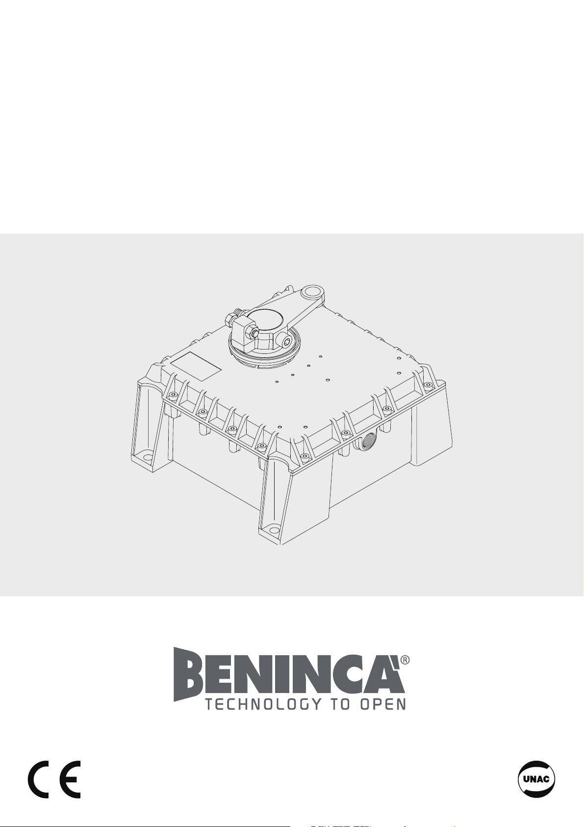
3
400
267
400
300
149
64
70
DU.110
DU.350
Dimensioni d’ingombro / Overall dimensions / Abmessungen
Dimensions d’encombrement / Dimensiones exteriores / Wymiary gabarytowe
Page 3
4
1
Arresto in chiusura.
Stop when closing.
Endanschlag zur Schließung.
Arrêt en fermeture.
Tope de cierre.
Chwytak blokujący podczas zamykania.
Arresto in apertura.
Stop when opening.
Endanschlag zur Öffnung.
Arrêt en ouverture.
Tope en apertura.
Chwytak blokujący podczas otwierania.
2
Standard.
Standard.
Standard.
Standard.
Standard.
Standard.
Interno.
Inside.
Innenraum.
Intérieur.
Interior.
Wnętrze obudowy
Apre.
Open.
Öffnen.
Ouvre.
Abre.
Otwarcie
Apre.
Open.
Öffnen.
Ouvre.
Abre.
Otwarcie
Posizione motoriduttore.
Reduction gear position.
Stellung Getriebemotor.
Position motoréducteur.
Posición del motorreductor.
Pozycja siłownika
Posizione motoriduttore.
Reduction gear position.
Stellung Getriebemotor.
Position motoréducteur.
Posición del motorreductor.
Pozycja siłownika
Anta.
Gate wing.
Torflügel.
Porte.
Hoja.
Skrzydło bramy.
Anta.
Gate wing.
Torflügel.
Porte.
Hoja.
Skrzydło bramy.
Anta.
Gate wing.
Torflügel.
Porte.
Hoja.
Skrzydło bramy.
Anta.
Gate wing.
Torflügel.
Porte.
Hoja.
Skrzydło bramy.
110° 110°
90° 90°
Muro.
Wall.
Wand.
Mur.
Muro.
Mur
Muro.
Wall.
Wand.
Mur.
Muro.
Mur
Muro.
Wall.
Wand.
Mur.
Muro.
Mur
Muro.
Wall.
Wand.
Mur.
Muro.
Mur
Apre.
Open.
Öffnen.
Ouvre.
Abre.
Otwarcie
Apre.
Open.
Öffnen.
Ouvre.
Abre.
Otwarcie
Page 4
5
Leva di collegamento.
Connection lever.
Anschlußhebel.
Levier de liaison.
Leva de conexión.
Dźwignia połączenia.
Staffa del motore.
Motor flask.
Motorbügel.
Etrier du moteur.
Acoplamiento al motor.
Strzemiączko silnika.
Staffa del gruppo di traino.
Drive unit flask.
Bügel der Zuggruppe.
Etrier du groupe de traction.
Acoplamiento del grupo de tracción.
Strzemiączko zespołu pociągnika.
Fermo meccanico per apertura regolabile DU.350ST.
Mechanical stopper for DU.350ST adjustable opening.
Einstellbarer mechanischer Anschlag für DU.350ST-Öffnung.
Butée mécanique pour ouverture réglable DU.350ST.
Tope mecánico para apertura regulable DU.350ST.
Mechaniczny ogranicznik służący do regulacji stopnia otwierania DU.350ST.
V
110°
70
200
200
X
Y
Esterno - Outside - Außen - Extérieur - Exterior - Zewnątrz.
Interno - Inside - Innen - Intérieur - Interior - Wewnątrz
Cancello con apertura ante a 110°.
Gate with 110° opening.
Tor mit Flügelöffnung bis 110°.
Portail avec ouverture des vantaux à 110°.
Cancela con apertura de hojas hasta 110°.
Brama z otwarciem skrzydeł na 110°.
130 30
X Y
115 40
100 50
85 60
70 70
55 80
In tabella si riportano alcune quote minime X in base
ad alcuni spessori di portone Y.
This table shows some min. X dimensions based
on gate thickness Y.
Die Tabelle enthält einige Mindestwerte X aufgrund
einiger Tordicken Y.
Dans le tableau sont indiqués quelques cotes minimales et quelques épaisseurs de porte Y.
En la tabla se exponen algunas cotas mínimas X en
base a algunos espesores del portón Y.
W tabeli podane są niektóre minimalne odległości
X w zależności od grubości bramy Y.
3
4
Page 5

6
Collegamenti elettrici / Wire diagram / Elektrische Anschlüsse
Branchements électriques / Conexiones eléctricas / Połączenia elektryczne
Legenda:
1 Motoriduttore DU.350N
2 Fotocellule FTC/FTM
3 Selettore a chiave CH (da esterno) o tastiera digitale
4 Lampeggiante LAMP
5 Antenna AW
6 Centrale elettronica.
Legenda:
1 Motoreducer DU.350N
2 Photo-electric cells FTC/FTM
3 Key selector CH (external) or digital keyboard
4 Flash-light LAMP
5 Antenna AW
6 Electronic board.
Zeichenerklärung:
1 Getriebemotor DU.350N
2 Fotozelle FTC/FTM
3
Schlüssel-Selektor CH (außenliegend) oder Digital-Tastatur
4 Blinker LAMP
5 Antenne AW
6 Elektroschrank.
Légende:
1 Moteur-réducteur DU.350N
2 Photocellule FTC/FTM
3 Selecteur à clé CH (d’extérieur) ou clavier digital
4 Clignotant LAMP
5 Antenne AW
6 Centrale électronique.
Leyenda:
1 Motorreductor DU.350N
2 Fotocélulas FTC/FTM
3 Selectores a llave CH (de superficie).
4 Relampagueador LAMP.
5 AntenaAW.
6 Central electrónica.
Objaśnienia:
1 Siłownik DU.350N
2 Fotokomórki FTC/FTM
3 Przełącznik kluczowy CH (zewnętrzny) lub panel z przyciskami
4 Światło migające LAMP
5 Antena AW
6 Centralka elektroniczna
4
1
2
RG 58
6
3x1,5 min
230 V
5
2
1
2x1,5
2x1
2x1
4x1
4x1,5
4x1,5
N.B.: Tenere separati i cavi di potenza da quelli ausiliari.
N.B.: The power cables must be kept separated from the auxiliary cables.
Wichtig: Leistungskabel von Hilfskabeln getrennt halten.
N.B.: Séparer les câbles de puissance des câbles auxiliaires.
N.B.: Tener separados los cables de potencia de los auxiliares.
Uwaga: należy trzymać w oddali przewody zasilania od przewodów pomocniczych.
Page 6

9
WARNING
The product shall not be used for purposes or in ways
other than those for which the product is intended for and
as described in this manual. Incorrect uses can damage
the product and cause injuries and damages.
The company shall not be deemed responsible for the
non-compliance with a good manufacture technique of
gates as well as for any deformation, which might occur
during use.
Keep this manual for further use.
Qualified personnel, in compliance with regulations in
force, shall install the system.
Packaging must be kept out of reach of children, as it can
be hazardous. For disposal, packaging must be divided
the various types of waste (e.g. carton board, polystyrene)
in compliance with regulations in force.
The installer must supply all information on the automatic,
manual and emergency operation of the automatic system and supply the end user with instructions for use.
c
An omnipolar switch/section switch with remote
contact opening equal to, or higher than 3mm
must be provided on the power supply mains..
Make sure that before wiring an adequate differential
switch and an overcurrent protection is provided.
Pursuant to safety regulations in force, some types of installation require that the gate connection be earthed.
During installation, maintenance and repair, cut off power
supply before accessing to live parts.
Descriptions and figures in this manual are not binding.
While leaving the essential characteristics of the product
unchanged, the manufacturer reserves the right to modify
the same under the technical, design or commercial point
of view without necessarily update this manual.
CE Declaration of Conformity
Declaration in accordance with Directives 2004/108/CE(EMC); 2006/95/CE(LVD)
The Manufacturer:
AUTOMATISMI BENINCÀ SPA
Address:
Via Capitello, 45 - 36066 Sandrigo (VI) - Italy
Declares that the product:
Electromechanical actuator 230V AC for swing gates, model:
DU.350N - DU.350NV
conforms with the requirements of the following EU Directives:
• DIRECTIVE 2004/108/CE OF THE EUROPEAN PARLIAMENT AND COUNCIL, 15 December 2004, in
relation to the harmonisation of the legislation of member states regarding electromagnetic compatibility
, in abrogation of Directive 89/336/CEE, per the following harmonised standards:
EN 61000-6-2:2005, EN 61000-6-3:2007.
• DIRECTIVE 2006/95/CE OF THE EUROPEAN PARLIAMENT AND COUNCIL, 12 December 2006, in
relation to the harmonisation of the legislation of member states regarding electrical material intended to
be used within certain voltage ranges, per the following harmonised standards:
EN 60335-1:2002 + A1:2004 + A11:2004 + A12:2006 + A2:2006 + A13:2008; EN 60335-1-103:2003.
as applicable:
• DIRECTIVE 1999/5/CE OF THE EUROPEAN PARLIAMENT AND COUNCIL, 9 March 1999 in relation
to radio equipment and telecommunications terminals and the mutual recognition of their conformity, per
the following harmonised standards:
ETSI EN 301 489-3 V1.4.1 (2002) + ETSI EN 301 489-1 V1.4.1 (2002) + ETSI EN 300 220-3 V1.1.1
(2000) + EN 60950-1 (2001)
Benincà Luigi, Legal representative.
Sandrigo, 02/11/2010.
Page 7

10
Introduction
Thank you for choosing our DU.350N/DU.350NV ratiomotor.
All items in the wide Benincà production range are the result
of twenty-years’ experience in the automatism sector and
of continuous research for new materials and advanced
technologies.
We are, therefore, in the position to offer higly reliable
products that due to their power, effectiveness and useful
life, fully satisfy the final user’s requirements.
General information
For an efficient operation of these automatisms, the gate
must have the following features:
- good stoutness and stiffness
- every wing must have one only hinge (if necessary,
eliminate the others).
- all hinges must have positive clearances and permit
smooth and regular manual operations.
- when wings are closed their height have to fit together.
1. General features
This entirely concealing system does not alter the external
aspect of the gate.
Easy to use and reliable, this system can be installed on
any swing gate, up to 4m width per gate leaf (3 m max for
DU350NV model).
The movement is smooth and noiseless thanks to a lever
system that adjusts speed to the various operating phases.
The oil submersed geared motor prevents any water leakage
or condensate which might irremediably compromise the
motor operation.
No electric locks are required as the irreversible system
ensures the locking of the gate leaves.
The system is easy to install. Once the casing is underground,
in fact, the geared motor is fixed with stainless steel nuts
and screws.
The system is released by hand through the special lever
supplied (item SB.DU350L), or through customized key (item
SB.DU350K).
The foundation casings are treated by cataphoresis and
the cover is varnished for a longer duration and excellent
aesthetic result.
With the application of the DU.180N device, a 180° opening
is obtained (with gate leaves not wider than 2 m). The
DU.180N can be adopted for the automation of special
passages.
2. Mechanical stops (fig. 1)
The gate to automate must have an opening and closing
mechanical stop as the DU.350N/DU.350NV is not equipped
with electro-magnetic limit stops. The DU.350FC limit switch
kit, easy to install and adjust, is in any case available.
3. Laying of the foundation casing
Refer to instructions supplied with the DU.350CF foundation
casing.
4. Motoreducer fixing
4.1
Fix the motoreducer with the 4 stainless steel M10
hexagon nut (part of the supply) that are fitted onto the
screws projecting from the embedded box.
P.N. In the box there are 8 screws; use the ones that are suitable
to the requirements as per instructions given in Fig.4.
4.2
Connect the drive unit with the motor flask through the
connection lever (Fig. 7)
4.3
With the door leaf resting onto the closing stopper, adjust
the screw V, Fig. 7, at a distance of 1/2mm from the linking
lever (in the case of standard mounting only).
4.4
The mechanical stopper is available for the adjustable
opening (DU.350ST) to be positioned in the special
housing of the drive bracket, as indicated in Fig. 7.
4.5
Before tightening the M10 nuts, check that the gear motor
rests solidly on the bottom of the casing. Conversely,
shim where required, keeping in mind that the gear motor
should rest flat (check by using a level).
5. 110° opening (Fig. 8)
For a 110° opening, calculate that the X quota between pivot
and angle of the beam permits rotation taking account of
the thickness of the Y door.
6. 180° Opening
The 180° opening can be made through the special device
Art. DU.180N. This solution is advisable for gates up to
2m wide. Wider gates can be used, but operation is less
smooth.
CAUTION
All Benincá products are covered by insurance policy for
any possible damages to objects and persons caused by
construction faults under condition that the entire system
be marked CE and only Benincá parts be used.
TECHNICAL DATA
DU.350N DU.350NV
Power supply 230 Vac 230 Vac
Power drawn 310 W 310 W
Current drawn 1,4 A 1,4 A
Torque 450 Nm 270 Nm
Motor insulation class F F
Noise level <70 dB <70 dB
Operating time at 90° 18 s (1). 11 s (1).
Door leaf max. weight 500 kg 500 kg
Door leaf max. 3,5 m (2) 3 m (2)
Jogging 40% 40%
Lubrication AGIP Blasia 32 AGIP Blasia 32
Capacitor 12,5 µF 12,5 µF
IP class IP67 IP67
Weight DU.350N/350NV 20 kg 20 kg
Weight DU.350CF 16,2 kg 16,2 kg
(1) With braking disabled.
(2) Automation for longer wings is also possible but running would
not be so smooth and regular.
Page 8

19
A B
C D
Libro istruzioni per l’utilizzatore
User’s handbook for the user
Handbuch für den Verbraucher
Manuel d’instructions pour l’utilisateur
Libro de instrucciones para el usuario
Instrukcja obsługi dla użytkownika
DU.350N
DU.350NV
Sblocco a leva SB.DU350L
SB.DU350L lever release
Hebelentsicherung SB.DU350L
Système de déblocage à levier SB.DU350L
Desbloqueo con palanca SB.DU350L
Odblokowanie za pomocą dźwigni SB.DU350L
Sblocco a chiave personalizzata SB.DU350K
How to release with SB.DU350K customized key
Entsicherung mit dem kundenspezifischen Schlüssel SB.DU350K
Déblocage à clé personnalisée SB.DU350K
Desbloqueo con llave personalizada SB.DU350K
Odblokowanie przy użyciu specjalnego klucza SB.DU350K
Page 9

20
ITALIANO ENGLISH
Norme di sicurezza
• Non sostare nella zona di movimento della porta.
• Non lasciare che i bambini giochino con i comandi o in
prossimità delle ante.
• In caso di anomalie di funzionamento non tentare di riparare
il guasto ma avvertire un tecnico specializzato.
Manovra manuale e d'emergenza
In caso di mancanza dell’energia elettrica o di guasto, per
azionare manualmente le ante procedere come segue:
Sblocco a leva SB.DU350L (fig. A e B):
• inserire la chiave in dotazione C e ruotarla, seguendo il
verso della freccia in rilievo sullo sblocco.
• tenendo la chiave ruotata, spingere l’anta fino a farla
ruotare di qualche grado.
• levare la chiave;
È ora possibile aprire e chiudere manualmente l’anta.
Il portone si ribloccherà automaticamente non appena
riportato nella posizione iniziale o quando si riattiverà il
motore.
Sblocco a chiave personalizzata SB.DU350K (fig C e D):
• Togliere il tappo ”T” di protezione della serratura inserito
a pressione.
• Inserire la chiave ”C” e ruotarla fino a che oppone
resistenza.
• Ruotare la leva ”L” in uno dei due sensi fino a fine
corsa.
È ora possibile aprire e chiudere manualmente l’anta.
Per ripristinare il movimento automatico, riportare la leva
”L” nella posizione originale, girare ed estrarre la chiave
personalizzata ”C” e richiudere il tappo ”T”; la prima
manovra ripristinerà il normale funzionamento.
Manutenzione
• Controllare periodicamente l’efficienza dello sblocco
manuale di emergenza.
• Astenersi assolutamente dal tentativo di effettuare
riparazioni, potreste incorrere in incidenti; per queste
operazioni contattare un tecnico specializzato.
• L’attuatore non richiede manutenzioni ordinarie, tuttavia
è necessario verificare periodicamente l’efficienza dei
dispositivi di sicurezza e le altre parti dell’impianto che
potrebbero creare pericoli in seguito ad usura.
Smaltimento
Come indicato dal simbolo a lato, è
vietato gettare questo prodotto nei rifiuti
domestici in quanto alcune parti che
lo compongono potrebbero risultare
nociv e per l’ ambiente e la salut e
umana, se smaltite scorrettamente.
L’apparecchiatura, pertanto, dovrà
essere consegnata in adeguati centri di
raccolta differenziata, oppure riconsegnata al rivenditore
al momento dell’acquisto di una nuova apparecchiatura
equivalente. Lo smaltimento abusivo del prodotto da
parte dell’utente comporta l’applicazione delle sanzioni
amministrative previste dalla normativa vigente.
Attenzione
Tutti i prodotti Benincà sono coperti da polizza assicurativa
che risponde di eventuali danni a cose o persone causati
da difetti di fabbricazione, richiede però la marcatura
CE della ”macchina” e l’utilizzo di componenti originali
Benincà.
Safety rules
• Do not stand in the movement area of the door.
• Do not let children play with controls and near the
door.
• Should operating faults occur, do not attempt to repair
the fault but call a qualified technician.
Manual and emergency operation
In the event of power failure or faults, the gate can be
manually operated as follows:
SB.DU350L lever release (Fig. A and B):
• Introduce the key C supplied and turn it following
the direction shown by the arrow embossed on the
release.
• while keeping the key turned, push the gate, making it
turn for some degrees.
• remove the key;
The gate can be now opened and closed by hand. The
gate will lock again automatically as soon as it reaches the
initial position or when the motor is activated again.
How to release with SB.DU350K customized key (Fig.
C and D).
• Remove the “T” protective cap from the lock.
• Introduce the “C” key and turn it until you feel
resistance.
• Turn the ”L” lever in either directions, until reaching the
limit switch.
The gate can be now opened and closed by hand. To
reset the automatic movement, move the “L” lever to the
original position, turn and extract the “C” customized key
and close the “T” cap again. The regular operation will be
reset with the first movement.
Maintenance
• Every month check the good operation of the emergency
manual release.
• It is mandatory not to carry out extraordinary maintenance
or repairs as accidents may be caused. These operations
must be carried out by qualified personnel only.
• The operator is maintenance free but it is necessary to
check periodically if the safety devices and the other
components of the automation system work properly.
Wear and tear of some components could cause
dangers.
Waste disposal
As indicated by the symbol shown, it
is forbidden to dispose this product as
normal urban waste as some parts might
be harmful for environment and human
health, if they are disposed of incorrectly.
Therefore, the device should be disposed
in special collection platforms or given
back to the reseller if a new and similar
device is purchased. An incorrect disposal of the device
will result in fines applied to the user, as provided for by
regulations in force.
Warning
All Benincá products are covered by insurance policy for
any possible damages to objects and persons caused by
construction faults under condition that the entire system
be marked CE and only Benincá parts be used.
Page 10

23
Pos. Denominazione - Description - Bezeichnung - Dénomination - Denominación - Określenie Cod.
A
Vite senza fine
DU.350N
Worm screw
DU.350N
Welle DU.350N
Vis sans fin
DU.350N
Tornillo sin fin
DU.350N
Śruba dwustronna
DU.350N
9686372
Vite senza fine
DU.350NV
Worm screw
DU.350NV
Welle DU.350NV
Vis sans fin
DU.350NV
Tornillo sin fin
DU.350NV
Śruba dwustronna
DU.350NV
9686373
B
Albero uscita
Du.350N
Output shaft
DU.350N
Welle DU.350N Arbre DU.350N
Eje de salida
DU.350N
Wał wyjściowy
DU.350N
9686379
Albero uscita
Du.350NV
Output shaft
DU.350NV
Welle DU.350NV Arbre DU.350NV
Eje de salida
DU.350NV
Wał wyjściowy
DU.350NV
9686380
1
Motore Motor Motor Moteur Motor Silnik
9686013
2
Sblocco Release Entblockung Déblocage Desbloqueo Zespół odblok.
9686396
3
Sblocco + Leva Release + Lever
Entblockung +
Hebel
Déblocage +
Levier
Desbloqueo +
Palanca
Zespół odblok. +
Dźwigienka
9686018
4
Carter superiore Upper cover Gehäuse Carter Cárter Karter
9686376
5
Guarnizione Gasket Dichtung Guarniture Junta Uszczelka
9686377
6
Carter inferiore Lower cover Gehäuse Carter Cárter Karter
9686378
7
Chiave sblocco Key Schlüssel Clé
Llave de desbloq.
Dźwignia odrygl.
9686071
8
Camme finec. Limit stop cam Nocke Came
Levas fin. de car.
Krańcówka
9686323
9
Cavo alimentaz. Power cable Stromkabel.
Câble alim.
Cable alimen.
Przewód zasilania
9686371
10
Leva Lever Hebel Levier Palanca Dźwigienka
9686374
8
4
4
A
B
5
6
1
9
5
Page 11

AUTOMATISMI BENINCÀ SpA - Via Capitello, 45 - 36066 Sandrigo (VI) - Tel. 0444 751030 r.a. - Fax 0444 759728
 Loading...