

Page 1

i
Skymap IIIC
& Tracker IIIC
Pilot Guide & Operating Manual
Manual Revision: SM2105-07 SIIIC Pilots Guide
Unit Software Version 1.11+ (System Model Packages SM4000 & TR4000)
Aeronautical Database: - Supplied courtesy of Jeppesen®
2000 Skyforce Avionics Ltd,
(A subsidiary of Honeywell Inc)
5 The Old Granary,
Boxgrove,
Chichester,
West Sussex PO18 0ES,
UK
Information in this document is subject to change without notice. Honeywell reserves the right
to change or improve its products and to make changes in the content without notification.
Page 2

ii
Table of Contents
1 INTRODUCTION .............................................................................................................................. 1-1
WARNING........................................................................................................................................ 1-1
DEFINITIONS, ACRONYMS AND ABBREVIATIONS.................................................................... 1-2
Definitions..................................................................................................................................... 1-2
Acronyms and Abbreviations........................................................................................................ 1-4
A QUICK LOOK AT YOUR UNIT.................................................................................................... 1-6
Standard Accessories .................................................................................................................. 1-7
Optional Accessories.................................................................................................................... 1-7
2 GENERAL INFORMATION.............................................................................................................. 2-1
S
OFT KEYING
..................................................................................................................................... 2-1
S
CREEN ORIENTATION
....................................................................................................................... 2-1
S
OFTWARE ARCHITECTURE
................................................................................................................ 2-1
M
EMORY LOCATIONS
......................................................................................................................... 2-3
S
CREEN ICONS
.................................................................................................................................. 2-3
3 POWER AND ANTENNA CONSIDERATIONS ............................................................................... 3-1
P
OWER
.............................................................................................................................................. 3-1
A
NTENNA CONSIDERATIONS (SKYMAP
IIIC
ONLY
)................................................................................ 3-3
4 QUICK REFERENCE GUIDE .......................................................................................................... 4-1
I
NTRODUCTION
................................................................................................................................... 4-1
I
NITIALISING YOUR UNIT
..................................................................................................................... 4-1
S
OFTWARE STRUCTURE
..................................................................................................................... 4-2
S
ELECTING DEMO MODE
.................................................................................................................... 4-2
D
ATABAS E SELECTION
....................................................................................................................... 4-3
A Q
UICK WORD ON
DIRECT TOS A
ND FLIGHT PLANS
....................................................................... 4-3
V
ISUAL
DIRECT TO A
ND DATA INTERROGATION
................................................................................ 4-4
DIRECT TO
A SPECIFIC LATITUDE
- A
ND LONGITUDE
......................................................................... 4-4
M
ANUAL
DIRECT TO A
ND DATA INTERROGATION
.............................................................................. 4-4
E
DITING/CREATING
A U
SER WAYPOINT MANUALLY
............................................................................. 4-5
E
DITING/CREATING
A U
SER WAYPOINT VISUALLY
............................................................................... 4-5
S
AVING
A U
SER WAYPOINT IN FLIGHT
................................................................................................ 4-5
E
DITING/CREATING
A F
LIGHT PLAN MANUALLY
................................................................................... 4-6
E
DITING/CREATING
A F
LIGHT PLAN VISUALLY
..................................................................................... 4-6
S
ELECTING
A F
LIGHT PLAN TO FLY
.................................................................................................... 4-7
S
ELECTING
A M
AP MODE NAVIGATION PRESENTATION
....................................................................... 4-7
V
IEWING
ETAS/S
KIP WAYPOINTS
....................................................................................................... 4-7
T
EN NEAREST SEARCH
...................................................................................................................... 4-8
S
ETUP MAP FUNCTIONS
..................................................................................................................... 4-8
S
ETUP OF NAVIGATION FUNCTIONS
..................................................................................................... 4-9
C
LEAR MEMORY
.............................................................................................................................. 4-10
5 TITLE AND HELP SCREENS .......................................................................................................... 5-1
S
ELF TEST AND INITIALISATION
........................................................................................................... 5-1
M
AIN MENU SCREEN
.......................................................................................................................... 5-2
N
OTE PAD SCREEN
............................................................................................................................ 5-3
6 GPS STATUS SCREENS (SKYMAP IIIC ONLY) ............................................................................ 6-1
A
DJUSTING TIME AND DATE
................................................................................................................ 6-3
S
ETTING LOCAL TIME OFFSET
............................................................................................................ 6-4
S
ETTING PRESENT POSITION
.............................................................................................................. 6-4
7 DATA INPUT .................................................................................................................................... 7-1
8 FLIGHT PLANNING SCREENS.......................................................................................................8-1
Page 3

iii
U
SER WAYPOINTS
.............................................................................................................................. 8-1
V
IEWING USER WAYPOINTS
................................................................................................................ 8-3
M
ANUAL USER WAYPOINT EDITING
..................................................................................................... 8-4
G
RAPHICAL USER WAYPOINT EDITING
................................................................................................ 8-5
E
DITING USER AIRPORTS
................................................................................................................... 8-6
F
LIGHT PLANS
................................................................................................................................... 8-6
M
ANUAL FLIGHT PLAN BUILDING AND EDITING
.................................................................................... 8-7
M
ANUALLY INSERTING A WAYPOINT INTO A FLIGHT PLAN AND MANUAL
DIRECT TO............................ 8-8
G
RAPHICAL VIEWING AND EDITING OF FLIGHT PLANS
........................................................................ 8-11
9 MAP MODE SCREENS.................................................................................................................... 9-1
D
ATA INTERROGATION AND GRAPHICAL
DIRECT TO .......................................................................... 9-2
Airport Information........................................................................................................................ 9-3
Beacon Information ...................................................................................................................... 9-4
General Icon Information.............................................................................................................. 9-5
Airspace Interrogation .................................................................................................................. 9-6
10 NAV MENU SCREENS ................................................................................................................ 10-1
S
ELECTING A FLIGHT PLAN
............................................................................................................... 10-2
T
EN NEAREST
.................................................................................................................................. 10-3
Airports....................................................................................................................................... 10-3
Beacons ..................................................................................................................................... 10-5
11 MAP MODE WITH NAV INFORMATION..................................................................................... 11-1
V
IEWING EN-ROUTE
ETA’
S AND DIRECT-TO PAGE
............................................................................ 11-2
Direct-To..................................................................................................................................... 11-3
A
RRIVAL AT AN EN-ROUTE USER WAYPOINT
...................................................................................... 11-3
A
RRIVAL AT YOUR FINAL DESTINATION
............................................................................................. 11-4
A
LTERNATIVE NAVIGATION MAP MODES
........................................................................................... 11-5
TOPO ON / TOPO OFF Large Text Mode................................................................................. 11-5
TOPO ON / TOPO OFF CDI (Pseudo HSI) Mode: .................................................................... 11-6
12 DEMO MODE ............................................................................................................................... 12-1
13 E6-B CALCULATOR.................................................................................................................... 13-1
D
ENSITY ALTITUDE
/TAS/W
INDS ALOFT CALCULATOR
....................................................................... 13-1
V
ERTICAL NAVIGATION
(VNAV)........................................................................................................ 13-2
T
RIP/FUEL PLANNING
....................................................................................................................... 13-4
S
UNSET/SUNRISE CALCULATOR
. ...................................................................................................... 13-5
14 SETUP SCREENS ....................................................................................................................... 14-1
M
AP SETUP SCREENS
...................................................................................................................... 14-1
NAV M
ODE SETUP
.......................................................................................................................... 14-5
P
ERSONAL IDENTIFICATION NUMBER
(PIN) S
ETUP
............................................................................ 14-7
Auto Power-On Lock .................................................................................................................. 14-9
I
NSTALLATION AND DIAGNOSTIC SCREENS
........................................................................................ 14-9
Screen Position Setup.............................................................................................................. 14-10
View Logs................................................................................................................................. 14-10
Engineering Log.................................................................................................................................. 14-10
GPS Receiver Information Log............................................................................................................ 14-11
Clear Memory........................................................................................................................... 14-11
Data In/Out...............................................................................................................................14-13
Output Test.......................................................................................................................................... 14-14
Total Number Of Pages 123
Page 4

iv
Appendices
APPENDIX 01: WARNING SCREENS ...................................................................................................1
RAM Lost Warning ...........................................................................................................................1
Memory Battery Warning..................................................................................................................1
PIN Lock Warning ............................................................................................................................2
Lock Out Warning.............................................................................................................................2
New Data Card Warning ..................................................................................................................3
APPENDIX 02: MEMORY CARDS .........................................................................................................1
D
ATA AREAS
..........................................................................................................................................1
C
HANGING THE MEMORY CARD
. ..............................................................................................................1
M
INIMUM SAFE ALTITUDES
(MSA)..........................................................................................................2
Flight Plan building...........................................................................................................................2
During Flight.....................................................................................................................................2
W
ORLDWIDE
ICAO C
ODES
. ...................................................................................................................2
APPENDIX 03: HOW DOES GPS WORK? ............................................................................................1
W
HAT IS
GPS?......................................................................................................................................1
H
OW DOES IT WORK
? ...........................................................................................................................1
A
CCURACY AND RELIABILITY
..................................................................................................................2
APPENDIX 04: DIFFERENTIAL FUNCTIONS (SKYMAP IIIC ONLY)...................................................1
W
HAT IS
DGPS? ...................................................................................................................................1
H
OW DOES
DGPS W
ORK
?....................................................................................................................1
U
SES OF
DGPS ....................................................................................................................................1
D
ATA CONNECTION
................................................................................................................................2
APPENDIX 05: SKYMAP IIIC SERIAL DATA OUTPUT SENTENCES. ...............................................1
NMEA 0183 D
ATA FORMAT
...................................................................................................................1
RS-232C AR-NAV D
ATA FORMAT
........................................................................................................3
APPENDIX 06: SERVICE AND WARRANTY.........................................................................................1
Page 5

v
Screen Index
Screen 1: Title Screen ...................................................................................................................... 5-1
Screen 2: Main Menu Screen........................................................................................................... 5-2
Screen 3: GPS Status Screen .......................................................................................................... 6-1
Screen 4: Date and Time Adjustment Screen ................................................................................ 6-3
Screen 5: Local Time Offset Screen ............................................................................................... 6-4
Screen 6: Present Position Setup Screen ...................................................................................... 6-4
Screen 7: Flight Planning Mode Cover Screen.............................................................................. 8-2
Screen 8: User Waypoint Viewer Screen........................................................................................ 8-3
Screen 8A: User Airfield Edit Screen.............................................................................................. 8-6
Screen 9: Manual User Waypoint Edit Screen ............................................................................... 8-4
Screen 10: View and Edit User Waypoints on the Map Screen.................................................... 8-5
Screen 10A: View Map Screen......................................................................................................... 6-5
Screen 11: Flight Plan Selection Screen ........................................................................................8-6
Screen 12: Flight Plan Program/Edit Screen ........................................................................ 8-7, 10-3
Screen 13: Database Selection Screen .......................................................................................... 8-8
Screen 15: DIRECT TO Destination Input Screen ......................................................................... 8-9
Screen 16: Item Selection Screen ................................................................................................... 8-9
Screen 19: View and Edit Flight Plans On Map Screen .............................................................. 8-11
Screen 20: Demo Mode Setup Screen .......................................................................................... 12-1
Screen 21: Setup Cover Screen .................................................................................................... 14-1
Screen 22 : Map Customisation Screen ........................................................................................ 14-1
Screen 22A: Point Features Data Class Setup Screen................................................................ 14-4
Screen 22B: Line Features Data Class Setup Screen. ................................................................ 14-4
Screen 22C: Airspace Data Class Setup Screen ......................................................................... 14-5
Screen 23: NAV Mode Customisation Screen ............................................................................. 14-5
Screen 24: PIN Setup Cover Screen ............................................................................................. 14-7
Screen 25: PIN Incorrect Screen ................................................................................................... 14-7
Screen 26: PIN Change & Power-On Lock Enable Screen ......................................................... 14-8
Screen 27: PIN Change Screen ..................................................................................................... 14-8
Screen 28: Installation and Diagnostics Cover Screen .............................................................. 14-9
Screen 30: Engineering Log Screen ........................................................................................... 14-10
Screen 31: GPS Receiver Information Screen (Skymap IIIC only)........................................... 14-12
Screen 32: Memory Clear Entry Screen...................................................................................... 14-12
Screen 33: Memory Clear Cover Screen .................................................................................... 14-13
Screen 35(T): Data Input/Output Setup and Test Screen .............................................................. 7-2
Screen 35: Data Input/Output Setup and Test Screen .............................................................. 14-14
Screen 35B: GPS Source Change Warning Screen ................................................................... 14-14
Screen 37: Aviation Interface Output Test Screen (Skymap IIIC only).................................... 14-15
Screen 38: Basic Map Mode Screen ...............................................................................................9-1
Screen 39: Map Mode with Joystick Active Screen ...................................................................... 9-2
Screen 40: Map Mode Airfield Info Screen..................................................................................... 9-3
Screen 40A: Map Mode Beacon Information Screen .................................................................... 9-4
Screen 40B: Airspace Information Screen.................................................................................... 9-6
Screen 40C: Map Mode General Information Screen .................................................................... 9-5
Screen 41: NAV Menu Cover Screen ............................................................................................ 10-1
Screen 41A: View ETA’s and Skip Leg Screen. ........................................................................... 11-2
Screen 42: Flight Plan Selection Screen ...................................................................................... 10-2
Screen 43: Ten Nearest Airfields Screen...................................................................................... 10-3
Screen 44: Airfield Information Screen ......................................................................................... 10-4
Screen 45: Ten Nearest Beacons Screen..................................................................................... 10-5
Screen 46: Beacon Information Screen........................................................................................ 10-5
Screen 47: Map Mode with NAV Information Screen .................................................................. 11-1
Screen 47A: Large Text & Map NAV Information Screen. .......................................................... 11-5
Screen 47B: Large Text & CDI (Pseudo HSI) NAV Information Screen..................................... 11-6
Page 6

vi
Screen 48: NAV Information and TP IMMINENT Flags Showing - Enroute Screen.................. 11-3
Screen 49: NAV Information and TP IMMINENT Flags Showing - Final Screen ....................... 11-4
Screen 50: Representation of Screen 47 Showing DEMO MODE Flag ..................................... 12-2
Screen 51: RAM Lost Warning Screen ........................................................................... Appendix 01
Screen 52: Memory Battery Warning Screen................................................................. Appendix 01
Screen 54: Power On Security PIN Entry Screen .......................................................... Appendix 01
Screen 55: Lockout Screen ............................................................................................ Appendix 01
Screen 56: Flight Plan Change Warning Screen ........................................................... Appendix 01
Screen 57: E6-B Calculator Cover Screen ................................................................................... 13-1
Screen 58: Density Altitude, True Air Speed & Winds Aloft Screen .......................................... 13-1
Screen 59: V NAV Setup Screen.................................................................................................... 13-3
Screen 60: Trip / Fuel Flight Plan Select Screen ......................................................................... 13-4
Screen 61: Sunset/Sunrise Calculator Screen............................................................................. 13-5
Screen 62: Notepad Screen ...............................................................................................................5-3
Page 7

1-1
1 INTRODUCTION
All of us at Honeywell congratulate you on choosing this product. You are now the owner of one of the
most sophisticated yet simple-to-use Navaids available today. We underst and you probably can't wait
to see it in action but before you try to use it do please take the time to read through this Manual and
understand its many interesting and useful features. Time spent in fam iliaris ing yourself with your new
Bendix/King unit will be more than repaid by trouble-free operation later, and more importantly safe
and accurate navigation.
We have made the operation of this unit as intuitive as possible through the use of sof t keying and onscreen help, thus reducing users' dependence on the Manual. You should ver y quick ly find that handling
it efficiently and expertly becomes second nature to you. Don't be afraid to experiment. No matter which
Key you activate, your unit will not be damaged. If you do get into a mess, simply switch off and back on
again to reset all functions. W e must mention j ust one word of caution. Never remove the memory
card whilst the unit is switched on and never attempt to switch the unit on when there is no
memory card fitted.
Whichever model of our equipment you have chosen, we at Honeywell are sure you will be pleased with
its performance. We thank you for your custom and wish you many happy and safe hours flying.
WARNING
The Global Positioning System (GPS) satellite constellation is operated by the Department of Defence
(DoD) of the United States, which is solely responsible for its accuracy and maintenance. Although
declared fully operational on July 17th 1995, the system is still under development and subject to
changes, which could affect the accuracy and performance of all GPS equipment.
Use this equipment at your own risk. Your new Bendix/King equipment is a precision navigation aid
but like any navaid it can be misused or m isinterpr eted and so becom e uns afe. You are str ongly advised
to read and fully understand this Manual before using it. Your unit has a DEMO MODE or simulation
facility that allows you to practice with it before you begin using it for actual navigation.
Whenever you are using the unit for navigation in the air you should treat it as a supplemental
navigation system. You should always carefully compare indications from your Bendix/King equipment
with the information available from all other navigation sources including NDB’s, VOR’s, DME's, visual
sightings, charts, etc. For safety, any discrepancies observed should be resolved immediately.
The altitude calculated by GPS equipment is geom etric height above a theoretical mean sea level of a
mathematically calculated ellipsoid that approx imates to the shape of the earth. This altitude can diff er
significantly from that displayed by your pressure altimeter. You must therefore NEVER USE GPS
ALTITUDE FOR VERTICAL NAVIGATION OR TERRAIN CLEARANCE.
This equipment is not a replac ement for your chart. It is intended as an aid to VFR navigation only.
The database within the equipment has been compiled from the latest of ficial inform ation available, and
although every care has been taken in the compilation, the manufactur ers will not be held res ponsible f o r
any inaccuracy or omissions therein.
Page 8

1-2
DEFINITIONS, ACRONYMS AND ABBREVIATIONS
Definitions
alphabetic: any of the following characters (b/ is a space):
b/ABCDEFGHIJKLMNOPQRSTUVWXYZ
alphanumeric: any of the following characters (b/ is a space):
b/ABCDEFGHIJKLMNOPQRSTUVWXYZ0123456789
baud: bits per sec
barometric altitude: pressure altitude corrected for barometric altimeter setting
bearing to user waypoint: bearing from the present position to the ac tive user waypoint measured
clockwise relative to true or magnetic north (true is implied unless magnetic is specified)
cross track error: distance from the present pos ition to the nearest point on the desired c ourse, and
the direction (right or left) from the desired course to the present position
cursor field: a character position or group of adjacent character positions on which a cursor can
appear
data entry field: A data entry field is a data field where the ENTER, SET or SELECT button must be
pressed before data entered in the field becomes effective. A data entry field can be a single or
multiple character cursor field. During data entry, the active cursor field remains reverse video.
data field: a character position or group of adjacent char acter positions which display a single data
item; a data field may be a single character cursor field, or may contain multiple characters.
data list: an ordered list of data elements which a given cursor field can accept
desired track: The angle, which the desired flight path m akes with respec t to true north at the point
nearest the present position. Magnetic desired track uses the local magnetic variation.
destination: If the active user waypoint is not in the active flight plan, the active us er waypoint is the
destination. If the active user waypoint is in the active flight plan, the final user waypoint in the flight
plan is the destination.
distance to user waypoint: distance from the present position to the active user waypoint
en route safe altitude: the highest m inim um s afe altitude whic h will be encountered for a given flight
path (present position to destination, via flight plan if appr opriate; or a f light path being analysed by trip
planning)
flashing: active for .75 sec ∀.05 sec, inactive for .25 sec ∀.05 sec
ground speed: absolute value of the rate of change of position
headwind: difference between true airspeed and ground speed when true airspeed is more than
ground speed
knots: N.M./hr
minimum safe altitude: Minimum safe altitude is the highest minimum off route altitude for any
sector within a 10 N.M. square centred at a given position. A minimum off route altitude of 7000 f eet
or less clears all known obstruc tions and terrain in a se ctor by 1000 feet; a minim um off route altitude
Page 9

1-3
greater than 7000 feet clears all terrain by 2000 feet. A sector is an area bounded by a 1
o
latitude/longitude grid.
RAIM: Receiver Autonomous Integrity Monitoring - A technique whereby a GPS receiver determines
the integrity of the GPS navigation signals by a consistency check among redundant pseudo range
measurements.
scrolling region: a set of consecutive cursor fields which display a portion of a scroll lis t; "scroll up"
means that the data item in each cursor field in the scrolling region m oves to the preceding cursor
field. The data item in the first cursor field disappears from the page, and the last c ursor f ield displays
the next item in the scroll list; "s croll down" is the opposite. If there is other data assoc iated with the
data in the cursor fields (such as user waypoint numbers in flight plans), it also moves.
selected course: The angle, which the desired flight path m akes with respect to true north at the
active user waypoint. Magnetic selected course uses the magnetic variation at the active user
waypoint; if the active user waypoint is a VOR, the magnetic variation stored for that VOR is used.
special use airspace: any of the following: prohibited area, restricted area, warning area, alert ar ea,
MOA, Class CARSA, Class BTCA, unknown, danger, caution, training, CTA, or TMA type
standard rate turn: 3°/sec
tailwind: difference between ground speed and true air speed when ground speed is more than true
airspeed
terminal user waypoints: user waypoints that are duplicated within a country code or "unnam ed"
user waypoints associated with an approach that are assigned to distinct airports
time to user waypoint: distance to user waypoint divided by ground speed
track: angle of the aircraft's path over the ground measur ed clockwise relative to true or magnetic
north (true is implied unless magnetic is specified)
Page 10

1-4
Acronyms and Abbreviations.
AC: alternating current
ACT: active (user waypoint or flight plan)
ADF: automatic direction finder
ANSI: American National Standards Institute
APT: airport
ARTCC: air route traffic control centre
ASCII: American standard code for information interchange
ATC: air traffic control
ATF: aerodrome traffic frequency
ATIS: automatic terminal information service
A/C: aircraft
baud: or Baud Rate; a measurement of data transmission speed
BRG: bearing
CAA: Civil Aviation Authority
CAS: calibrated airspeed
com: communication
CDI: course deviation indicator
CTA: control area
CTAF: common traffic advisory frequency
CTR: centre
CWI: continuous wave interference
dB: decibels
DC: direct current
DIS: distance
DME: distance measuring equipment
DOT: United States Department of Transportation
EFIS: electronic flight instrument system
ELT: emergency locator transmitter
ESA: en route safe altitude
ETE: estimated time en route
FAA: Federal Aviation Administration
FAF: final approach fix
FAR: Federal Aviation Regulations
FPL: flight plan
FPM: feet per minute
FSS: flight service station
ft: feet
FT: feet
G: gravitational acceleration = 32.2 ft/sec5 = 19.3 kt/sec5
GAL: gallons
GPS: Global Positioning System
hr: hour
HSI: horizontal situation indicator
Hz: hertz
IAF: initial approach fix
IAP: instrument approach procedure
IEEE: Institute of Electrical and Electronics Engineering
IFR: instrument flight rules
in.: inches
INT: intersection
kHz: kilohertz
Kt.: knots
KΩ: kilohms
LAT: latitude
Page 11

1-5
LB: pounds
LED: light emitting diode
LON: longitude
LONG: longitude
LRU: line replaceable unit
m: meters
mA: milliamperes
MATZ: Military air traffic zone
MAHP: missed approach holding point
MAP: missed approach point
mB: millibars
MF: mandatory frequency
MHz: megahertz
mi: statute miles
min: minutes
MOA: military operation area
MSA: minimum safe altitude
msec: milliseconds
NDB: non-directional beacon
N.M.: nautical miles
NPA: non-precision approach
OBI: Omni-directional bearing indicator
OBS: Omni-directional bearing selector
PETE: pointer ETE
RAD: radial
REF: reference
RMI: radio magnetic indicator
RTCA: Radio Technical Commission for Aeronautics
SA: Selective Availability (intentional errors introduced by the DoD)
SAT: static air temperature
sec: seconds
SID: Standard Instrument Departure
SNR: signal to noise ratio
STAR: Standard Terminal Arrival Route
SUP: supplemental user waypoint
TAS: true airspeed
TAT: total air temperature
TD: time difference
TMA: terminal control area
TSO: technical standard order
UTC: universal co-ordinated time (same as Greenwich Mean Time)
V: volts
VHF: very high frequency
VNV: vertical navigation
VOR: very high frequency Omni-directional radio range
W: watts
wpt: user waypoint
ΦΦΦΦ
sec: microsecond
ΦΦΦΦ
V: microvolts
Ω: ohms
°°°°
C: degrees Celsius
°°°°
F: degrees Fahrenheit
Page 12
1-6
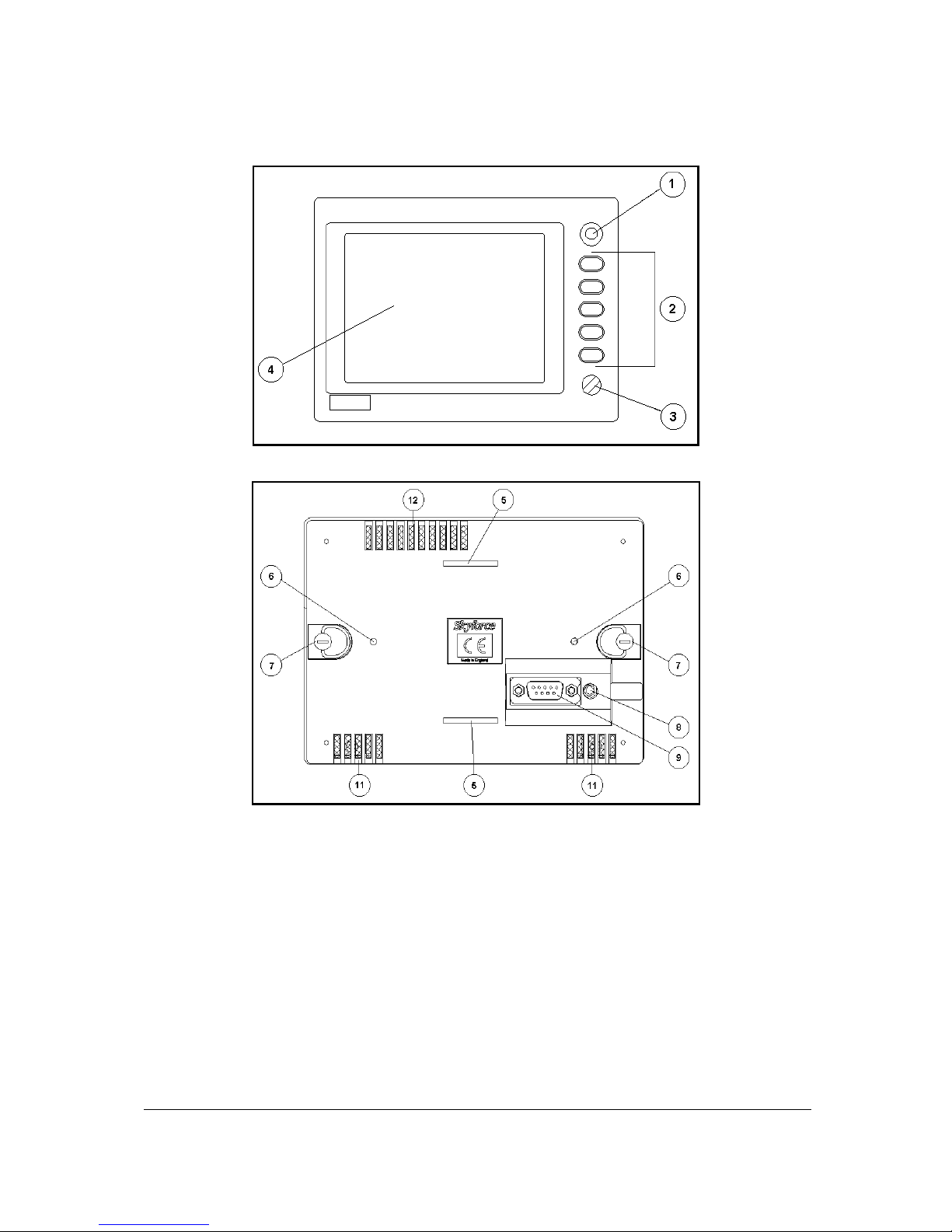
A QUICK LOOK AT YOUR UNIT
Skymap IIIC Front View
Skymap IIIC Rear View
KEY TO DRAWINGS
1. Joystick
2. Function Keys
3. ON / OFF / Brightness control
4. Full Colour TFT Liquid Crystal Display.
5. Leg Strap Slot.
6. Accessory Mounting Point.
7. Rear Cover Fasteners.
8. Antenna Socket (Skymap IIIC only)
9. Power/Data Connector.
Page 13
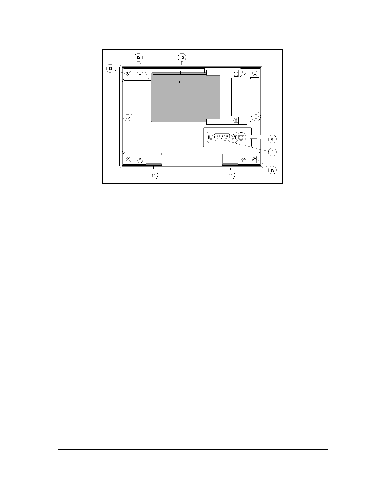
1-7
Skymap IIIC Rear View - Back Case Removed
KEY TO DRAWING
8. Antenna Socket (Skymap IIIC only)
9. Power/Data Connector.
10. Memory Card.
11. Cooling Air Intake (do not block).
12. Cooling Air Exhaust (do not block).
13. Rear Case Earth Tab (do not bend).
Standard Accessories
SM2100 Portable Antenna with Cable and Suction Cup (Skymap IIIC only)
SM2104 Carrying Case
SM2200 Leg Strap
SM2207 Cigar Adapter Cable (Skymap IIIC only)
SM2102 Power/Data Cable (Tracker IIIC only)
SM2105 Pilots Guide
SM2106 Getting Started Card
Optional Accessories
SM2201 Yoke Mount
SM2204 Panel Mount
SM2213 Panel Mount with Power/SMB Connector
SM2202 Rack Mount
SM2209 Gimbal Mount
SM2228 Pedestal Mount
SM2203 Avionics Interface Module (AIM)
KA92 Low Profile External Antenna
SM2212 SMB to BNC Adapter
SM2101 Antenna Extension Lead
SM2225/6/7 AC Power Adapter
SMP514 PC Interface Cable
FM25/26/2700 Flight Manager PC Software
Page 14

Page 15

2-1
2 GENERAL INFORMATION
This section of the Manual explains how your Bendix/King unit should be used and provides you with an
overview of the software architecture and screen presentation.
This Manual provides a detailed explanation of eac h of the individual Screens that your Bendix/King unit
displays, and will take you step by step through each of them. To simplify this process each Screen is
numbered and indexed at the front of this Manual for ref erence. For thos e users who wish to get stuc k
into operating the system immediately, the Quick Reference Section of the Manual has been designed to
get you up and running.
The operating system of the Bendix/King Sk ymap IIIC and Tracker IIIC has been developed from the
highly successful Skymap II software. This operating system greatly reduces the number of Key presses
necessary to activate the various functions, especially those most frequently used in the air. The
provision of a joystick makes it c onsiderably simpler to operate the unit and allows you fast and eff icient
access to most function s.
Soft Keying
You will notice that a label is drawn alongside each valid Key. Whenever a new function is selected,
by pressing a valid Key, a new screen is displayed along with its new Key labels. This capability of
drawing Key labels that are only applicable to a particular screen is referred to as ‘sof t keying’, and
allows one key to perform mu ltiple functions without the complications of multiple k ey presses on a
conventional keypad.
For the purpose of describing the function of a particular Key in this Manual, assum e that all the Keys on
the pictured screen drawings are numbered 1 - 5 from top to bottom. The ensuing text will use this
numbering sequence to refer to each specific Key. The number shown alongside the pictured sc reen
drawings refers to the number of the screen, which is called when that Key is pressed. By using thes e
numbers it is possible to follow the paths through the oper ating system f or all f unctions . If the word RET
is printed next to a Key, this means that after the Key function is performed the same screen is
RETurned. A good example of this is ZOOM IN. All sc reen drawings show the full Sk ymap IIIC version
of software in Landscape Standard mode. Variations affecting Tracker IIIC are described in the
accompanying text.
Screen Orientation
The Skymap IIIC and Tracker IIIC software can be run in one of f our dis play modes and so allows you to
mount the unit either horizontally (either landscape standard or inverse) or vertically (either portrait
standard or inverse). This enables the user to configure the unit f or either left or right handed oper ation
or place the Keys along the left, right, top or bottom edges of the case. The default setting on fir st s witch
on is Landscape Standard, and it is this mode that is used to illustr ate the functions of your unit in this
Manual. Refer to Map Setup Screens in the Setup Screens Section of this Manual if you wish to alter
your screen orientation.
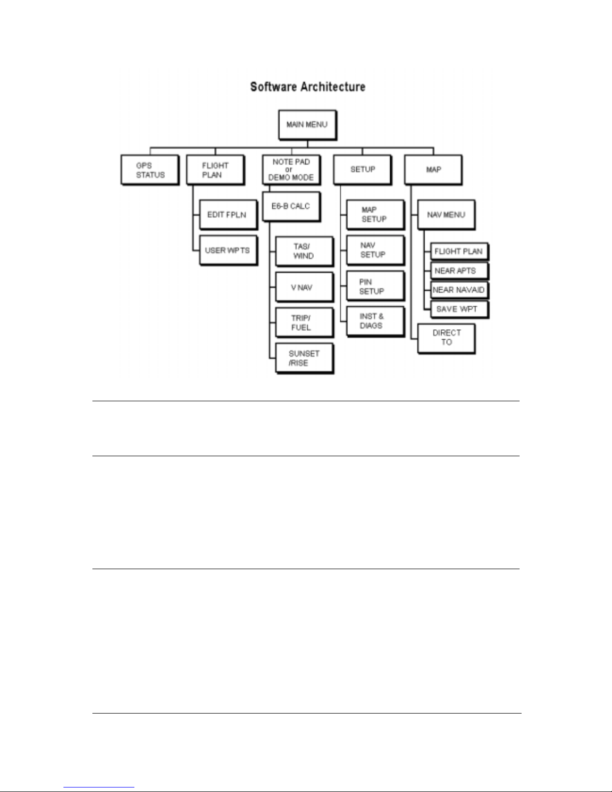
Software Architecture
The software in your Bendix/King unit is tree structur ed, an analogy can therefore be drawn between
the trunk of a tree and MAIN MENU. MAIN MENU is the heart of the operating structure and c an be
accessed by pressing the HELP key after power up or the MAIN MENU key at any other time.
MAIN MENU has 5 main software branches, which in turn have their own sub soft ware branc hes. The
diagram overleaf depicts the c om plete tree s tructur e and will serve as a good point of r efer ence whils t
you are familiarising yourself with your unit.
Page 16
2-2
GPS STATUS Shows satellite signal strength, allows UTC, local off set, date and position to be set,
which will speed up the initialisation of your unit.
FLIGHT PLAN Allows user defined user waypoints and flight plans to be edited/created.
EDIT FPLN Allows user defined flight plans to be edited /created either manually
or visually.
USER WPTS Allows user defined user waypoints, airports and mark er functions to
be edited/created either manually or visually.
DEMO MODE Allows you to practice operating the unit on the ground using a built-in simulator.
NOTE PAD Allows up to 4000 characters of text, previously downloaded from a PC using Flight
Manager™ software to be viewed. This Key is only available if DEMO MODE is not
running. DEMO MODE can only be selected from the first screen after s witching on
the unit.
E6-B CALC Allows the E6-B Calculator to be used.
TAS/WIND Allows density altitude, TAS and winds aloft to be calculated.
V NAV Allows vertical navigation to be Setup.
TRIP/FUEL Allows fuel and trip information to be calculated.
SUNSET/RISE Allows sunset and sunrise times to be calculated.
SETUP Allows Setup of map, navigation and input/output characteristics.
MAP SETUP Allows all map functions to be customised, including map tracking,
airport names, map units , map datum, display orientation, language,
minimum runway length/surface, extended track, auto zoom and
zoom level map de-clutter facility.
NAV SETUP Allows all the NAV functions to be custom ised, including CDI scale,
CDI display, CDI alarm, arrival alarm, auto next leg/leg selection
philosophy, turn anticipation and logging rate.
PIN SETUP Allows the PIN security function to be Setup.
INST & DIAGS Allows installation and diagnostics for data input/output and GPS
receiver (Skymap IIIC only) to be performed. Flight logs can be
viewed and various sections of memory can be cleared from here.
Page 17
2-3
MAP This is the primary operating mode of the unit.
NAV MENU Accesses all navigation functions and MSA inf orm ation. J oystick toggles
NAV Mode.
FLIGHT PLAN Allows a flight plan to be selected and edited.
NEAR APTS Allows emergency search of 10 nearest airports,
providing information and DIRECT TO capability.
Includes Jeppesen and user defined airports which
satisfies the minimum runway length and surface
requirements.
NEAR NAVAID Allows emergency search of 10 nearest beac ons (VOR's
and NDB's), providing information and DIRECT TO
capability.
SAVE WPT Allows your present co-ordinates to be saved in the next
available user waypoint number.
DIRECT TO Allows the user to perform a “goto” or DIRECT TO any point in the
internal or user defined database. It may also be used to obtain
information on any point in the database.
There are short cuts, which allow you to get to the primary operating mode, MAP mode, m ore easily;
but in general if you wish to get to a specific function in another branch of software, work your way
back up the present branch to MAIN MENU by pressing either the SAVE & EXIT, PREV PAGE or
MAIN MENU key. Then select the branch of software that contains the desired function you wish to
access.
Memory Locations
In the function descriptions, three types of m emory, EPROM, RAM and NVM, are mentioned. You m ay
find it useful to know where various types of inform ation are stored in order to mak e best use of the
equipment. The EPROM’s (Er asable Programmable Read Only Memor y) are in the memory card and
are used to hold the operating system and the database. T he m em ory card can be replaced per iodically
in order to upgrade the operating system and update the database. The RAM (Random Access Memory)
is built into the unit and is used to store all user-defined data such as User waypoints and Flight plans.
The RAM is maintained by battery power from an internal Lithium cell, which should be r eplaced by your
Bendix/King dealer every three years to prevent loss of user-defined data. The NVM (Non Volatile
Memory) is also built into the unit. It stores initialisation data, serial number, PIN number and
performance log details. This mem ory is non-volatile which means it is retained even if the memory
battery is removed. If you choose to activate the PIN number security feature (similar to that available on
many car radios) the non-volatile nature of the NVM ensures your PIN cannot be tampered with or
erased.
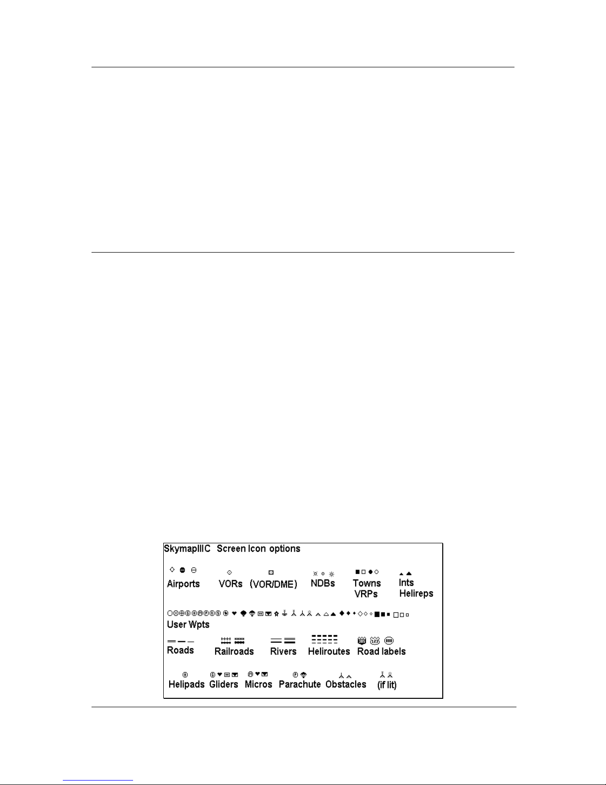
Screen Icons
When showing any map screen - airports, beacons, towns, inters ections , us er waypoints and many other
data classes are represented by symbols or icons, many of which are user selectable in the Map Setup
Screens. Please refer to the Setup Screens Section of this Manual for further details.
Page 18

Page 19
3-1
3 POWER AND ANTENNA CONSIDERATIONS
Power
Your unit is designed to operate from an exter nal s ourc e providing a voltage between 10V to 33V DC.
An optional AC Power (either 110V or 220/240V) Adapter is also available as an accessory for home
use.
A pre-wired connector is supplied with your unit. The tail end of which either has a Cigar Adapter
(Skymap IIIC) or flying leads (Tracker IIIC). The cable uses four coloured cores and a braided screen.
The red and blue cores of the cable s hould be connected to any DC supply between 10 and 33 Volts,
capable of supplying 2 Amps.
1. Connect the RED core via a 3 Amp fuse to the positive (+) side of a 10V-33V DC power
source.
2. Connect the BLUE core and the braided screen to the negative (-) side of the same power
source.
You may also power your unit from a 12 or 24 volt automobile type cigarette lighter socket. However
certain of these lack proper circuit protection and may provide an unreliable supply so we recomm end
that wherever possible an approved aircraft power source be installed by a licensed radio engineer.
The yellow and green cores are the data in (yellow) and data out (green) lines. If your unit is a Tracker
IIIC, the yellow core (data in) should be connected to the data output line of your GPS. Refer to the
Data Input Section of this Manual for more details.
If your unit is a Skymap IIIC, the yellow core (data in) can also be connected to the data output line of
another GPS, if required and the Skymap IIIC can be switched to Tracker mode and used as a
repeater for that GPS.
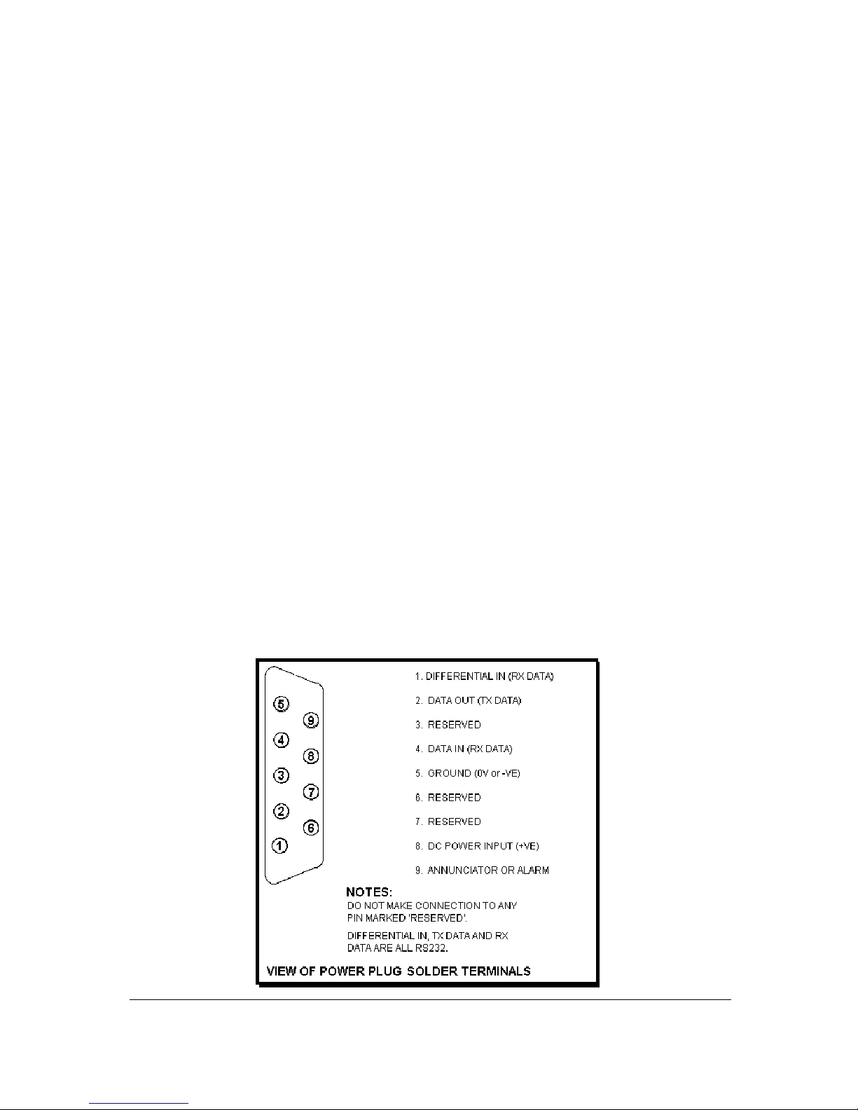
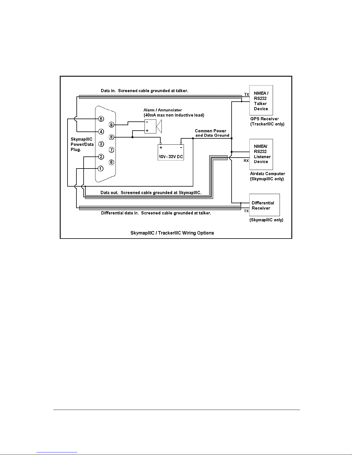
Your unit also has a differential serial data input and exter nal alarm outputs available on the 9 way
connector for optional use. The green core of the cable is connected to the s erial data output pin and
may be used to drive an AirData computer, a plotter or a data recording device (s ee Appendix 05 f or
details of data output).
Page 20
3-2
The data presented across the data output pins is controlled by the settings on Screen 35, Data I
Input/Output Setup and Test Screen. If you want to connect an external audio annunciator to your
unit, do so in accordance with the following drawing and activate it’s operation on Screen 23, NAV
Mode Customisation Screen by setting EXTERNAL ALARM to ON.
If you are not planning to connect either the green or yellow cores, please cut them back and
insulate the cut end. Please do not make connection to pins 3, 6 or 7.
Page 21

3-3
Antenna Considerations (Skymap IIIC only)
When positioning the antenna, always ensure that the domed (the opposite side to that which
carries the CE marking) face of the antenna is facing straight up to the sky and can “see” a
large area of the sky, preferably right down to the horizon. In order to provide a 3-dimensional fix,
Skymap IIIC needs to receive signals simultaneously from at least four satellites.
The radio signals from the G PS Navs tar s atellites ar e trans mitted in an extremely high frequency band
(1.5GHz). They can be regarded as having approximately the sam e penetration c apabilities as light.
This means that they are able to penetrate only transparent or very thin materials and will be blocked
by almost any material that blocks light.
At least four and at times up to eight GPS s atellites should always be in view from any place in the
world at any time. These can, however, be absolutely anywhere in the sky and so, to ensure
uninterrupted navigation it is essential that the antenna has direct line-of-sight contac t with as much
sky as possible.
If the position in which you wish to locate your Skymap IIIC is shielded from the sk y and the standard
antenna cable is not long enough for an acceptable installation bear ing the above guidelines in mind,
you may choose one of several options for remote antenna sitting. The simplest is to use the
Bendix/King remote antenna extension cable. T his allows the portable antenna to be extended by a
further 6ft (2 metres) thereby allowing mounting up to 12ft (4 meters) away from the m ain unit. The
antenna may be held in place there by using the rubber suction cup supplied (which s hould be s lotted
into the key hole in the antenna bracket) or fixed perm anently in position by using the countersunk
screw mounting holes in the antenna brack et. The rubber suction cup is ideal for tem porary use in
vehicles and light aircraft. The portable antenna is only splash proof and not fully waterproof. Never
mount this antenna permanently outside.
For permanent external antenna mounting an external magnetic mount antenna is available for ground
vehicles and an external low profile "tear drop" style antenna for aircraft. For m ore inform ation about
these accessories please contact your Bendix/King dealer.
Page 22

Page 23
4-1
4 QUICK REFERENCE GUIDE
This Section of the Manual is designed to provide you with a quick reference guide into the operation
of your Bendix/King unit; taking you step by step through the most comm on functions. If more detail is
required, please refer to the appropriate Sections in this Manual. The information contained within this
Section is equally applicable to the Tracker IIIC as it is to the Skymap IIIC. W here the Tracker IIIC
operation differs, the differences are explained in italic text after each paragraph.
Introduction
Your Bendix/King unit is operated via a joystick,
a series of 5 soft keys, and a rotary ON/OFF
switch. The joystick allows movement of the
pointer in MAP mode and is used for all forms
of data entry or selection. The appropriate key
labels for a particular page are configured in
software and drawn alongside the appropriate
black key. The rotary ON/OFF switch is used
for adjusting the brightness of your screen.
Before this screen is displayed, a warning shall
be given regarding the expiry date of the
Jeppesen
®
data. This must be acknowledged
before you may continue. Please refer to
Appendix 06 for details on obtaining data updates.
Initialising Your Unit
When an antenna is attac hed and has a good all round view of the sk y, the unit will achieve a pos ition
fix within 15 minutes. Ensuring that your GPS has rough UTC, date and position information can
significantly speed up this process. To check this switch on the unit, selec t the HELP key followed by
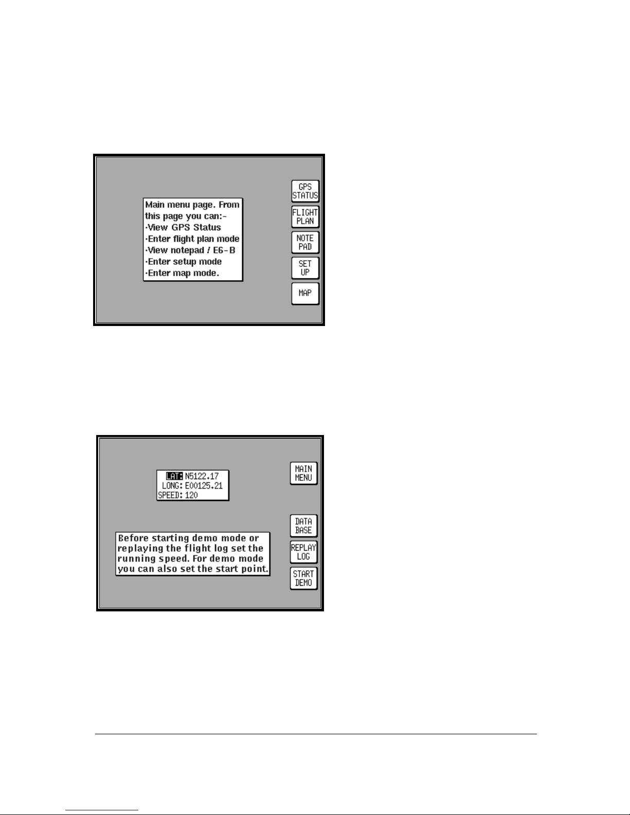
GPS STATUS.
Altering UTC & DATE: Select UTC & DATE,
followed by ADJUST UTC. Use the joystick to
adjust the time, then press SET. Now select
ADJUST DAT E and use the j oystick to adj us t the
date, and then press SET followed by GPS
STATUS.
Altering Present Position: Select SET POSN,
and use the joystick to adjust the latitude and
longitude to your approximate position and then
press SET. Alternatively select SET POSN and
then VIEW MAP. Move the joystick on the map
to your approximate position (using the ZOOM
IN/ZOOM OUT keys where applicable). Once
there select SET POSN to change the position.
When connected to an appropriate GPS output a “Tracker” unit will self initialise.
Page 24
4-2
Software Structure
Since the software is tree structured, an analogy can be drawn between the trunk of a tree and MAIN
MENU. This can be accessed after powering on the unit by pressing the HELP key. MAIN MENU has
5 main software branches, which are as follows:
•
GPS STATUS: Shows satellite signal
strength, allows UTC, Local Offset, Date
and Position to be set.
•
FLIGHT PLAN: Allows user defined
waypoints and flight plans to be
edited/created.
•
NOTEPAD: Allow access to NOTEPAD
and E6-B functions, or turns off DEMO
MODE. DEMO MODE can only be
activated in the first power on screen.
•
SET UP: Allows Setup of map, NAV, PIN
and input/output characteristics.
•
MAP: This is the primary mode of the unit.
As a rule when trying to get to a specific function in another branch of sof tware you should work your
way back down the present branch to MAIN MENU by pressing either the OK, PREV PAGE, SAVE &
EXIT or MAIN MENU key. Then select the branch of software that contains the des ired function you
wish to access. There are, short cuts allowing you to get to the primary mode, MAP mode, more
easily. GPS STATUS is replaced with DATA IN/OUT in “Tracker” units. Tracker units will
automatically be configured to accept data from external GPS/LORAN units.
Selecting Demo Mode
Demo Mode allows you to become fam iliar with
handling your unit on the ground by turning it
into a simulator. Demo Mode can only be
activated in the first title screen, available at
power on. Press DEMO MODE in the title
screen, and use the joystick to s elect the start
LAT and LONG and the ground SPEED you
wish to use. Alternatively you can press the
DATABASE key and select a data point from
the database as a start point (for more
information on achieving this please refer to
Database Selection in this Section of the
Manual). Once the desired LAT/LONG and
SPEED is entered press START DEMO.
Page 25
4-3
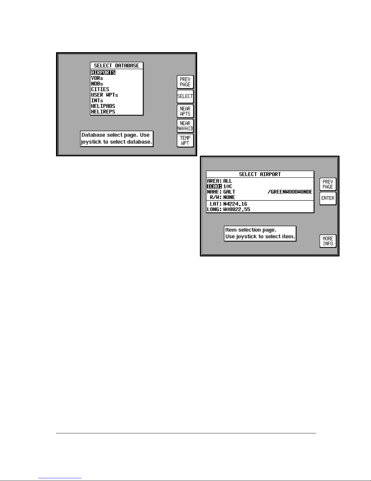
Database Selection
Both the internal (i.e.: Jeppesen and towns)
waypoints and user defined waypoints are
stored in your unit in a series of databases.
During the normal use of your unit you will
need to select items from these databases,
whether it is to find out airport frequency
information, or select a DIRECT TO point or
when creating a flight plan. In each case the
adjacent screen will appear. Use the j oystick
to highlight the database in which the desired
item is contained and press SELECT.
The second stage in the selection process requir es you
to choose the desired item. T his is achieved by using
the joystick. Once the desired item is displayed press
ENTER to select the item. If the item required is in an
aeronautical database (i.e.: AIRPORT, VOR etc) you
may well have the ability to narrow the area of search
by selecting a two letter identify in the AREA field. For
a complete list of two letter ICAO identifiers please
refer to Appendix 02 in this Manual. If the label in the
AREA field says ALL then the search will include all
countries available in your memory cards region.
A Quick Word On DIRECT TOs And Flight
Plans
A flight plan is a series of legs interspersed with waypoints, while a DIRECT TO is a one leg flight plan.
A DIRECT TO can be performed at any time. If a DIRECT TO is perform ed when a flight plan is
active, the flight plan will be put to sleep and the displayed navigation data in MAP mode will be to the
DIRECT TO point. You will always know when a DIRECT TO is r unning becaus e the DIRECT TO k ey
will be labelled DIRECT TO OFF. Pressing this key will cancel the DIRECT TO. If a flight plan was
previously running underneath it will automatically resume.
Page 26
4-4
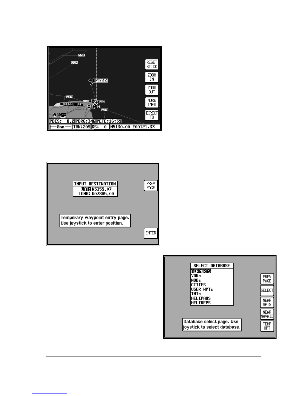
Visual DIRECT TO And Data
Interrogation
In MAP mode use the joystick to move the
pointer to the desired location, or obtain
distance/bearing and latitude/longitude from
present position. If you have a ground speed
your Bendix/King unit will calculate the time
to reach the tip of the on screen pointer. T his
information is displayed in the PETE (or
Pointer ETE) field. If you wish to invoke the
DIRECT TO function press the DIRECT TO
key. The unit will then provide you with full
navigation information to reach this point.
Alternatively if you wish to obtain more
information on a specif ic data point, whether
it is an airport, a section of controlled air space or a beacon, move the pointer onto it and press the
MORE INFO key. Once the pointer has been activated, by pushing the joystick, it will r emain active for
30 seconds; after which tim e it will automatically reset, if not moved. Alternatively you can force a
reset by pressing RESET STICK.
DIRECT TO a Specific LatitudeAnd Longitude
To perform a DIRECT TO a specified
latitude/longitude press the DIRECT TO key in
MAP mode, when the joystick is not active.
Then press TEMP WPT and use the joystick
to dial in the required latitude and longitude,
followed by ENTER. The unit will then provide
you with full navigation information to reach
this point.
Manual DIRECT TO And Data
Interrogation
Provided the pointer is not active in MAP mode, pr ess
the DIRECT TO key. You will now be able to select
the item from the databas e as explained in Database
Selection in this Section of the Manual. To activate
the item as the DIRECT TO , press the SELECT key
when the desired item is displayed. To get more
information on the item press the MORE INFO key
when the desired item is displayed. If you are running
a DIRECT TO an item, you can discontinue the
navigation by pressing the DIRECT TO OFF key.
Page 27
4-5
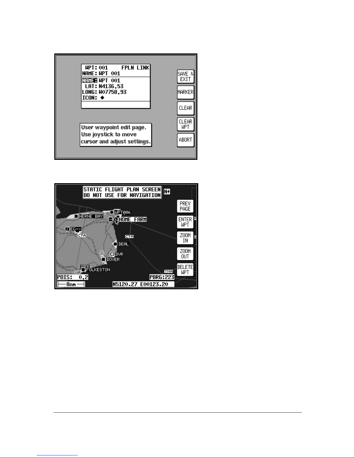
Editing/Creating A User
Waypoint Manually
From MAIN MENU select the FLIGHT
PLAN key, followed by USER WPTS.
Use the joystick to select the desired
user waypoint number or name. Then
press the EDIT key and use the joystick
to edit the NAME, LAT and LONG fields.
The entire user waypoint can be deleted
by pressing CLEAR WPT. If you only
wish to delete data in a particular field, as
opposed to the entire user waypoint,
move the cursor over the field label (i.e.
NAME, LAT, LONG) and press the
CLEAR key. To save a user waypoint
press SAVE & EXIT. Use the ABORT
key to return to MAIN MENU without
saving.
Editing/Creating A User
Waypoint Visually
From MAIN MENU select the FLIGHT
PLAN key, followed by USER WPTS.
You may then use the joystick to select a
specific user waypoint (either by number
or name). Press the VIEW MAP key and
the adjacent screen will be shown with
the previously selected user waypoint in
the centre of the screen. If the
previously selected user waypoint was
empty your last position will be
displayed. A user waypoint can then be
created as a distance and bearing from
the displayed position or as a
latitude/longitude. Press ENTER WPT
to save the user waypoint to the first
available memory location. An unwanted user waypoint can be removed by moving the pointer over it
and pressing the DELETE WPT key. If the user waypoint that you wish to delete is in a stored flight
plan the message [PRESENT IN FLIG HT PLAN] will be displayed. A second press on the DELETE
WPT key will however remove it, or you can move the joystick to cancel the delete. Use the PREV
PAGE key to return to screen entered from, saving any changes made.
Saving A User Waypoint In Flight
A user waypoint can be saved quickly in flight by pressing NAV MENU in MAP mode followed by
SAVE WPT. You will immediately be returned to MAP mode with your current position saved to the
next available user waypoint memory location.
Page 28
4-6
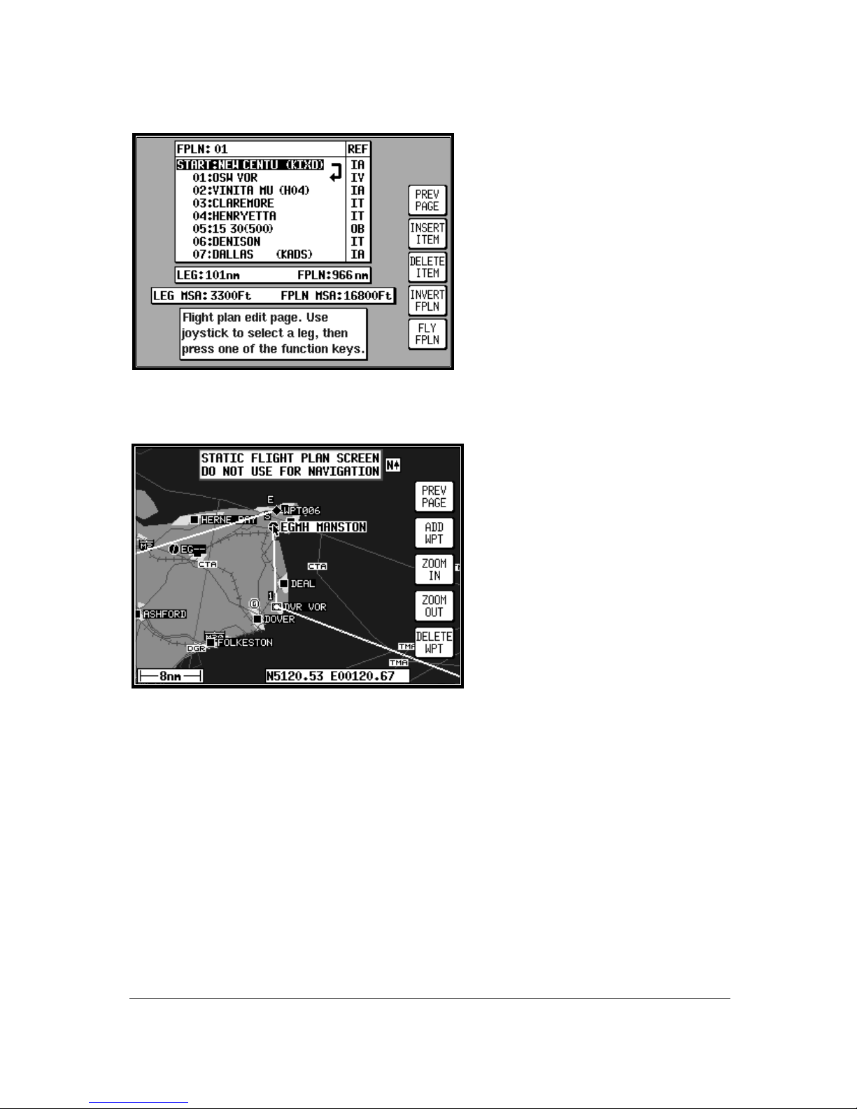
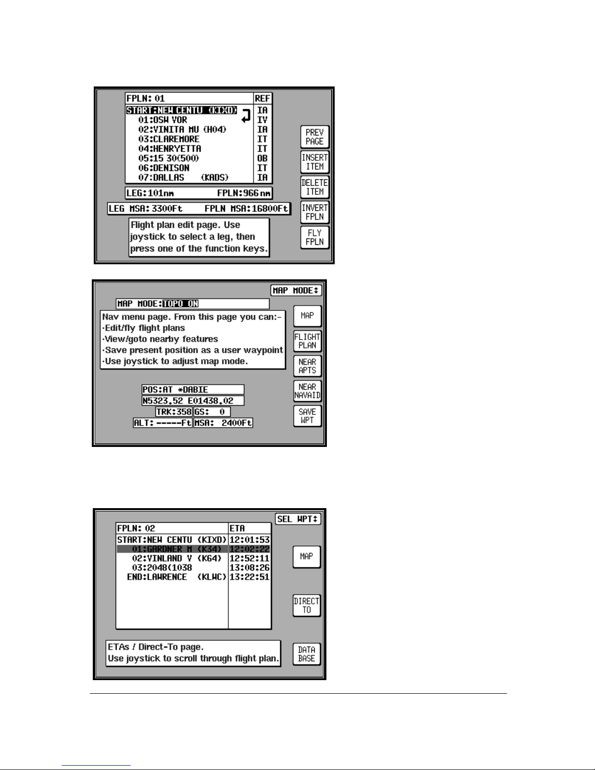
Editing/Creating A Flight Plan
Manually
From MAIN MENU select the FLIGHT PLAN
key, followed by EDIT FPLN. Use the
joystick to select the desired flight plan
number and then press SELECT. T o insert
an item press INSERT ITEM and follow the
Database Selection process explained ear lier
in this Section of the Manual. To rem ove an
item from the flight plan move the cursor
over the item using the joystick and press
DELETE ITEM. A flight plan can be
systematically built using the INSERT ITEM
key. The flight plan can be inverted by
pressing the INVERT FPLN key. If you wish
to fly the flight plan, ensure that the flight plan arrow (shown on the side of the flight plan list) is
highlighting the leg you wish to fly, the press FLY FPLN. Alternatively use the SAVE & EXIT key to
return to screen entered from, saving any changes made.
Editing/Creating A Flight Plan
Visually
From MAIN MENU select the FLIGHT
PLAN key, followed by EDIT FPLN. Use
the joystick to select the desired flight plan
number and then press VIEW MAP. If the
selected flight plan was empty, the adjacent
screen will appear showing your last
position, if it were not, the start point of the
flight plan will be shown in the centre of the
screen. If the desired f light plan was empty
you can use the joystick to move the
pointer to the desired start waypoint and
press ADD WPT (ADD WayPoinT). This
will place an S (for Start) next to the
waypoint. Move the pointer to the next
waypoint and press ADD WPT again. This will place an E (for End) next to the waypoint. In either
case when the ADD WPT key is pressed the unit will try to attach the turning point to a displayed
waypoint. If one is not available it will create a user waypoint in the next available memory location.
To systematically create additional legs, draw a line from the waypoint marked (E), with the pointer, to
the next waypoint and press ADD WPT again. You will notice that the last point in the flight plan will
always be labelled (E). Once you have finished building the flight plan pres s PREV PAGE, to detach
the pointer from the flight plan. This key, if pressed again will return to the screen entered from,
saving any changes made.
If you wish to add a new waypoint to a flight plan which you have stopped building, whether it is at the
start, the end or the middle of the flight plan, you will need to highlight the appropriate point (i.e.: either
the start waypoint (S), the end waypoint (E) or the leg line in which you wish to add a new waypoint).
As soon as you do this, the ADD WPT or GRAB LINE key will appear. Press the ADD WPT or GRAB
LINE k ey to join the pointer back to the flight plan line and then move it to the new waypoint (NOTE:
Key 2 reverts to ADD WPT) . Once over the new waypoint press ADD WPT, otherwise press PREV
PAGE to cancel this action. Unwanted waypoints can be removed by pointing at them and pressing
the DELETE WPT key. Use the PREV PAGE key to return to the screen entered from, saving any
changes made.
Page 29
4-7
Selecting A Flight Plan To Fly
From MAIN MENU select the MAP key,
followed by NAV MENU and FLIGHT
PLAN. Use the joystick to select the
desired flight plan number and then
press the SELECT key. Ensure that the
leg arrow is pointing at the initial leg that
is to be flown and press FLY FPLN.
The unit will immediately revert to map
mode with the navigation information
showing, using the pre-selected MAP
mode presentation.
Selecting A Map Mode
Navigation Presentation
When in MAP mode and navigating to a
waypoint, either with a DIRECT TO or as
part of a flight plan, the unit is in
Navigation MAP mode. The MAP
presentation can be varied from Large
Map to Large Text to a CDI (Pseudo HSI)
display. In all three modes there are a
further two options which are either T OPO
ON or TOPO OFF. In the TOPO ON
mode all classes of data can be set to a
specific colour. In the T OPO OFF mode
all cartographic data is automatically
removed and the Jeppesen NAV Data is
presented on a black background. The
presentation style can be changed at any time by pressing the NAV MENU key in MAP mode. The
joystick can then be toggled until the desired selection is shown in the MAP MODE field. T he new
selection, which will only be displayed when a DIRECT TO or flight plan is running, can be viewed by
pressing MAP.
Viewing ETAs/Skip Waypoints
When a flight plan is running the ETA to
each point in that flight plan can be viewed
by pressing the DIRECT TO key on the
map. On entry to the adjacent sc reen the
cursor highlights the waypoint in
MAGENTA that is currently being
navigated to. If ATC clear you onto END:
LAWRENCE, for example, you can use
the Direct-To waypoint function to amend
the Flight Plan quickly without having to
edit the Flight Plan. Use the joystick to
move a BLACK highlight over END:
LAWRENCE, then press DIRECT TO.
This function is not available in External
GPS Mode.
Page 30
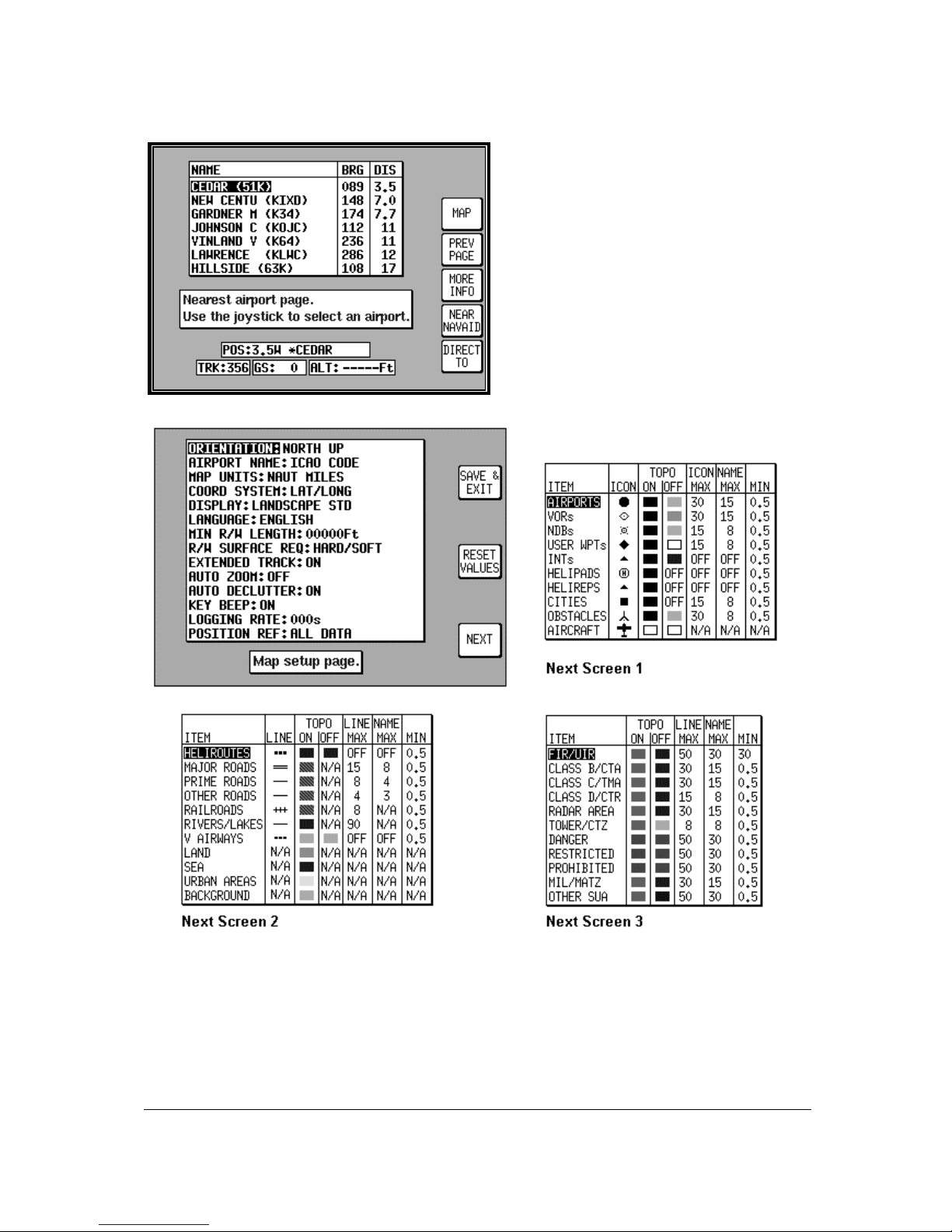
4-8
Ten Nearest Search
The ten nearest airports or beacons can be
displayed by either pressing NAV MENU or
DIRECT TO in MAP mode, followed by either
NEAR APTS (for airports) or NEAR NAVAID
(for beacons). T he desired information will be
presented dynamically as a bearing and
distance from your present position. Any
displayed item can be instantly navigated to by
pressing the DIRECT TO k ey. Alternatively the
MAP key can be used to return the user to
MAP mode.
Setup Map Functions
The above screens allow the mapping f unctions to be configured. The initial screen is reached by
pressing SET UP in MAIN MENU, followed by MAP SETUP. The subsequent screens are r eached by
pressing the NEXT key.
Page 31

4-9
On the initial page, each of the displayed features can be set by using the joystick. The features are
as follows:
ORIENTATION: Set either in Track Up or North Up.
AIRPORT NAMES: Labels airports in MAP mode either with ICAO code, airport or city names.
MAP UNITS: Sets all map units to ether nautical miles, statute miles or kilometres. If miles are
selected, all lengths and altitudes will be reported in feet. If k ilometres are selected, all lengths and
altitudes will be reported in metres.
COORD SYSTEM: Determines whether the unit operates with reference to Lat/Long, UTM or OSGB.
DISPLAY: Sets orientation of the display into either one of four positions.
LANGUAGE: Sets language to English, French, German or Spanish.
MIN R/W LENGTH: Sets the minimum length of runway required for ten nearest airports.
R/W SURFACE REQUIRED: Sets minimum runway surface required for ten nearest airports.
EXT TRACK: Turns on or off the extended track line, which is drawn ahead of your present position in
the direction of your present track.
AUTO ZOOM: Turns on or off. When flying the last leg of a flight plan or when f lying a DIRECT T O,
as soon as the distance to the destination drops below ½ the sc ale bar setting, the unit automatically
zooms. Auto Zoom can be disabled by simply pressing the ZOOM OUT key.
AUTO DECLUTTER: Turns on or off. If a higher priority icon label (Airport) is found to clash with a lower
priority icon label (City) already on the screen, the lower priority icon label will be removed.
KEY BEEP: Turns the key beep on or off.
LOGGING RATE: Sets the rate in seconds at which you log your position and loads it into a 2000 point
cyclic memory. To log a specif ic flight use the CLEAR LOG key, in the Clear Memory scr een. (Please
refer to the Clear Memory section below). T he flight can be replayed in DEMO MODE. (Please ref er to
the Selecting DEMO MODE section above).
POSITION REF: Defines the reference to which your position is given in MAP MODE, either to all
available data, VORs only or VORs and Airports only.
Next Screens 1, 2 and 3 are accessed by repeatedly pressing the NEXT key. They allow you to
choose the level of zoom at which you wish each of the classes of data to become visible and at which
level of zoom you want their corresponding labels to become vis ible. You can als o s et the icon or line
style for many of the data classes and set their display colours for both T OPO ON and TOPO OFF
display modes.
Any changes made in any of these screens will be saved once the SAVE & EXIT key has been
pressed. At any time the RESET VALUES key can be pressed to return your unit to the default
settings on that particular screen. If you wish to reset all setup options (including NAV SETUP
options) to their default setting press the CLEAR SETUP key in Clear Memory screen.
Setup of Navigation Functions
The adjacent screen allows the navigation
functions to be configured. It can be reached
by pressing SET UP in MAIN MENU, followed
by NAV SETUP.
Page 32

4-10
Each of the displayed features can be set by using the joystick. They are as follows:
CDI SCALE: Sets the full scale deflection of displayed CDIs to 0.3, 1.0, 2.5 or 5.0nm.
CDI DISPLAY: Either turns the CDI display off, or sets it to either a numeric or bar display.
CDI ALARM: Switches the CDI alarm on or off. When on, it is activated at full scale deflection.
WPT ALERT: Sets the distance away from your destination waypoint at which you wish the audio and
visual arrival alarms to be activated. This value is always in nautical miles.
AUTO LEG SELECT: When switched on, the unit will automatically determine which is the most
appropriate leg to fly when calling up a flight plan.
AUTO NEXT LEG: When switched on, the unit will automatically sequence you on to the next
waypoint in a flight plan when it has deemed that the current waypoint has been passed. When
switched off the user will be expected to press the NEXT LEG key in MAP mode to sequence on to the
next waypoint in the flight plan.
TURN ANTICIPATION: Turn Anticipation provides navigation along a curved path segment to ensure a
smooth transition between two adjacent legs in the flight plan.
FLIGHT PLAN DISPLAY: Allows a choice of displaying the full flight plan or just the ac tive leg on the
map screen.
INTERNAL (ARRIVAL and CDI) ALARM: These alarms can be switched on or off.
EXTERNAL (ARRIVAL and CDI) ALARM: These alarms can be switched on or off.
Any changes made in this screen will be s aved once the SAVE & EXIT key has been pressed. At any
time the RESET VALUES key can be pressed to return your unit to the default settings. If you wish to
reset all setup options (including MAP SETUP options) to their default setting press the CLEAR
SETUP key in the Clear Memory screen.
Clear Memory
To clear down specific parts of your units
memory press SET UP in MAIN MENU,
followed by INST & DIAGS and CLEAR
MEMORY. You will then be asked to enter
you’re your PIN. Unit default is 1234. You
are now in the Clear Memory screen. Each
block of memory in your unit can be cleared
down individually. CLEAR FPLNs will
remove all your flight plans. CLEAR WPTS
will remove all your user waypoints.
CLEAR SETUP will restore all the default
settings in MAP SETUP and NAV SETUP.
CLEAR LOG will clear the last flight
information, the 2000 flight logged data
points and all running timers.
Page 33

5-1
5 TITLE AND HELP SCREENS
To switch the unit on, rotate the On/Off/Brightness control fully clockwise.
Your unit produces a variety of tones and alarms to assist you in correct operation. At this stage only
two types of tone need concern you. These are:
1 short beep sounds when you press a valid Key.
2 short beeps sound when you press a Key that is not assigned.
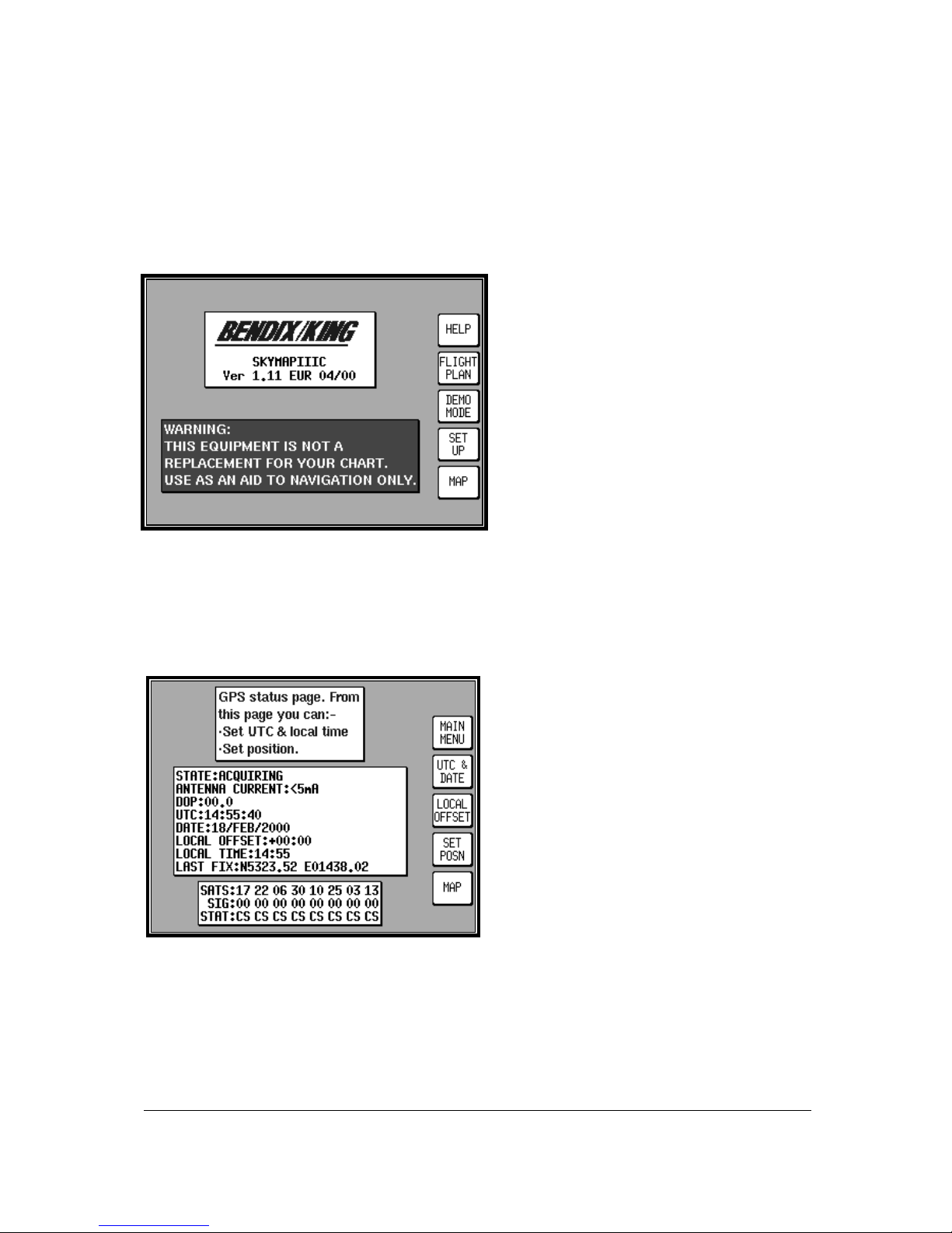
Screen 1: Title Screen
The Title Screen appears each tim e the unit is s witched on, after the J eppesen
®
database expiry date
has been acknowledged.
Key 1 calls Screen 2, which is the Main Menu Screen.
Key 2 calls Screen 7, which is the Flight Planning Mode Cover Screen.
Key 3 calls Screen 20, which is the Demo Mode Setup Screen. (If , since being switched on, the unit
has received valid fix information fr om the internal GPS receiver (Skymap IIIC) or from an external
device (Tracker IIIC), Key 3 DEMO MODE will for safety reasons be blanked and disabled.) T his is
the only Screen on which Demo Mode can be activated.
Key 4 calls Screen 21, which is the Setup Cover Screen.
Key 5 calls Screen 38, which is the Map Mode Screen.
To switch the unit off, rotate the On/Off/Brightness control fully counter clockwise.
WARNING: Do not force the control knob past its end stops.
Self Test and Initialisation
When the Title Screen is initially displayed, the unit carries out a series of internal check routines
automatically. These are:
1. Verification that the unit has been factory initialised. This consists of a chec k to see if there is a
special code in NVM. If there is no initialisation code in the NVM a message saying UNIT NOT
INITIALISED will be printed across the centre of the Screen and the unit will be totally disabled. This
is a security feature, safeguarding against theft of the unit and attempted er asure of your PIN from the
NVM. (If your unit is stolen and the NVM is erased or replaced in an attempt to reset the PIN, the thief
will still not be able to use or sell the unit because these special high security factory initialisation
codes will be missing.)
Page 34

5-2
2. A check for RAM cor ruption. If RAM has been lost or cor rupted due to a severe ‘glitch’ or loss of
power in the memory battery a RAM clear will be performed on the aff ected areas and Screen 51,
Ram Lost Warning Screen, will be displayed (Refer to Appendix 01).
3. A check of the internal Lithium battery voltage. If the internal battery voltage is low, Screen 52,
Internal Battery Warning Screen, will be displayed (Refer to Appendix 01).
4. A check to see whether the Automatic Power-On Lock function has been enabled (see Screen 26
for further details). If it is enabled, Screen 54, Power On Security PIN Entry Screen, will be displayed
after 5 seconds (or if any Key is pressed before this). If when switched on it is found that three
unsuccessful attem pts have been made to enter the Unlock PIN, Screen 55, Lockout Scr een, will be
displayed (Refer to Appendix 01).
5. A check to see if a new memory card has been f itted. T his involves comparing the software version
number held in NVM with that of the current memory Card. If a change of card is detected, the
integrity of all flight plans will be checked and if any discrepancies are f ound Screen 56, Flight Plan
Change Warning Screen, will be displayed (Refer to Appendix 01).
6. If the unit is a Skymap IIIC the GPS receiver circuitry will be tested and if any problems are found, a
NO REPLY message will be indicated in the STATUS field of Screen 3, GPS Status Screen.
If the unit passes all checks 1 to 6 above no warnings will be given
Main Menu Screen
Screen 2: Main Menu Screen
On Skymap IIIC units, Key 1 calls Screen 3, which is the GPS Status Sc reen. On Trac ker IIIC units ,
Key 1 is labelled DATA IN/OUT and will cause Screen 35, Data input/output Setup and Test Screen, to
be displayed. Key 2 calls Screen 7, which is the Flight Planning Mode Cover Screen. Key 3 will read
NOTE PAD if DEMO MODE was not selected on Sc r een 1. Pres s ing Key 3 when labelled NOTE PAD
will call screen 62, which is the NOTE PAD display screen and will also give access to Screen 57,
which is the E6-B Calculator Cover Screen (Ref er to Section on E6-B Calculator ). If Dem o Mode has
previously been activated, Key 3 will read DEMO OFF. Pressing DEMO OFF will then switch Demo
Mode off and return to Screen 2 with Key 3 reading NOTE PAD. Key 4 calls Screen 21, which is the
Setup Cover Screen. Key 5 calls Screen 38 or 47, which are MAP Mode and MAP Mode with NAV
Information Screens.
Page 35

5-3
Note Pad Screen
The Note Pad Screen (Screen 62) is accessed by pressing Key 3 on Screen 2, Main Menu Screen.
Screen 62: Notepad Screen
The Note Pad function allows you to load up to 4000 characters of text into your GPS unit from a
personal computer running the 'Flight Manager ' flight planning software, then recall the tex t on a spec ial
Note Pad screen during flight.
The Note Pad text can contain any information you want. Typical uses include checklists, en-route
weather downloaded before the flight from DUAT S, special instruction f or an unfamiliar destination etc.
Using the 'Flight Manager' software you can prepare and store a library of Note Pad files and load the
relevant one into your Bendix/King unit to suit your day's flying.
Screen 62 also gives access to the E6-B Calculator Screens.
Page 36

Page 37

6-1
6 GPS STATUS SCREENS (Skymap IIIC only)
Screen 3: GPS Status Screen
Pressing Key 1, GPS STATUS, in Main Menu, accesses this Screen.
The GPS Status Screen will display the receiver STATUS. This can be any of the following:
BAD ALMANAC <3 SATS DIFFERENTIAL ACQUIRING
2D FIX 3D FIX POOR DOP POS PROP
The meanings of these displays are:
BAD ALMANAC means the GPS receiver's inform ation c oncerning s atellite positions is out of date. If
this occurs the unit should be left alone with the antenna connected and in view of the sky for
approximately 15 minutes during which period it will automatically lock onto a satellite and load an upto-date almanac.
<3 SATS means that according to the current information available, there are less than thr ee satellites
in view and a fix can not be calculated. This message is very rarely displayed.
DIFFERENTIAL This word will be displayed in conjunction with 2D FIX or 3D FIX and means that the
Skymap IIIC has a fix and is also receiving differential correction signals from an external sour ce.
(Refer to Appendix 04 for further details concerning differential operation.)
ACQUIRING means the unit is currently searching for satellites or is loading inf ormation from one or
more satellites.
2D FIX means the unit is calculating position in two dimensions (i.e. latitude and longitude only, with no
height information).
3D FIX means that the unit is calculating position in thr ee dimensions and c an give latitude, longitude
and height information.
POOR DOP means that the unit is unable to calculate position owing to the poor geometry of the
visible satellites. (DOP stands for Dilution of Precision.)
POS PROP means that navigation has been temporarily lost and the Skymap IIIC is dead- reckoning
(or propagating) its position based on the last known position, track and ground speed. It will not
dead-reckon for more than a few seconds at a time.
Page 38

6-2
Other information that is displayed on this Screen includes:
DOP (Dilution of Precision), This is a number between 00.0 and 99.0 that represents the dilution of
quality of the calculated fix due to satellite geometry. 00.0 is best, 99.9 is worst. If this figure is
greater than 5.0, performance of the system is likely to be degraded because some of the visible
satellites appear too close to each other. DOP is calculated from the angular separation between the
various visible satellites. Greater separation r esults in better fix geometry and a lower DOP. (T his
DOP figure is not measured in any specific units.)
UTC/DATE, which is Universal or Greenwich Mean Time and Date.
LOCAL OFFSET, which is the difference between UTC and local time.
LOCAL TIME, which is calculated by adding Local Offset to UTC.
LAST FIX. If the unit does not have a current valid fix, this is the position at which it last had a f ix. If
the unit has a fix, this is the present position.
SATS (eight satellite numbers), SIGS (signal strength for each satellite) and STAT (status of each
satellite).
Each satellite has a PRN (Pseudo Random Noise) or identification number. The satellite PRN
numbers are displayed in a line beside the word SATS. The two digit number under each PRN
number is an indication of the signal strength being received from that satellite ex pr ess ed in ter ms of a
percentage. Best is 99, worst is 00. These numbers can be used f or finding and elim inating elec trical
interference. Readings of 60 and above indicate a good installation.
Under each signal strength number is a two character code. These indicate the status of each
satellite. These codes are: CS, CA, AS, FA, BD, MD, TA, EA, and AP. Thes e relate to the eight
possible receiver modes and are detailed below.
CS : Code Search. This is the receiver's initial stage in acquiring a satellite. It means that the receiver
is trying to match its internal code to the satellite signal.
CA: Code Acquire. This means the satellite code has been received and matched to the receivergenerated code.
AS: AGC Set. This m eans the satellite str ength has been assessed and the Autom atic Gain Control
has been set.
FA: Frequency Acquire. This means the receiver has correctly locked onto the satellite data
frequency.
BD: Bit Sync Detect. This means the receiver is synchronised with the satellite's data bit stream.
MD: Message Detect. This means the receiver is synchronised with the satellite's message stream.
TA: Time Available. This m eans the satellite is fully locked in and has s ent down UTC tim e and date
information to the receiver.
EA: Ephemeris Acquire. This m eans the receiver is r eading the constellation health status m essage
from the satellite. This usually takes around two m inutes and is a function that is performed in the
background even if the receiver has a fix.
AP: Available for Position. This m eans the satellite is fully locked in and tes ted and can be used for
calculating position. A minimum of three satellites are necessary for a 2D fix.
Key 1 returns to Main Menu. Date, Time, Local Tim e Offset and Pr esent Position can be adjusted by
selecting one of Keys 2, 3 or 4. Direct access to the MAP Mode is available by pressing Key 5.
Page 39

6-3
When using the Sk ymap IIIC for the first tim e (or after it has been relocated by more than 100 miles
since it was last used) setting up the present position ( to within 50 miles or s o) and ensur ing that UTC
and Date are correct (to within a few minutes) will consider ably speed up the TT F F ( time to first f ix) . It
is not absolutely necessary to do this, since given time, the receiver is quite capable of working out its
own position.
Adjusting Time and Date
Screen 4: Date and Time Adjustment Screen
Pressing GPS STATUS in Main Menu f ollowed by UTC & DATE accesses this Screen. Pressing Key
3, ADJUST UTC, places a c ursor over the firs t digit of the Hour s value on the tim e display. T he value
can then be increased or decreased by moving the joystick up or down. Pushing the j oystick to the
right then moves the cursor to the next digit. Similarly, moving the joystick to the left moves the c urs or
back along the data entry field. When the time is adjusted, the inf ormation will only be saved if you
press Key 1 SET.
Pressing Key 4 puts a cursor onto the Date entry field. The date is adjusted in the sam e way as tim e.
With the curs or over the Month when the joystick is moved up or down, the first thr ee characters of
each month are scrolled together i.e. J AN, FEB, MAR, APR etc . Adj us ting the year work s in the s ame
way. Your Bendix/King unit is fully Year 2000 compliant. Only after pressing Key 1 SET is the new
date saved. The Time and Date will be autom atically corrected as soon as the first satellite reac hes
TA (time available) status . If any satellite is already at status TA or above, user inputs of time and
date will be ignored.
Page 40

6-4
Setting Local Time Offset
Screen 5: Local Time Offset Screen
Pressing GPS STATUS in Main Menu, f ollowed by LOCAL OFFSET, acc esses this Screen. W hen
this Screen initially appears a cursor will be active in the data entry field. The hour’s value can be
adjusted between the limits of +12 and -12 by using the joystick. The cursor can then be moved to the
right to adjust the minutes to one of two values, 00 or 30. Only after pressing Key 1, SET is the
information saved and the display will revert to Screen 3, GPS Status Screen.
The local offset is held in RAM and added to UTC time when calculating ETA's. Default value is
+00:00. It is important to set local offset correctly to ensure any ETA’s given are correct.
Setting Present Position
Screen 6: Present Position Setup Screen
Pressing GPS STATUS in Main Menu, followed by SET POSN, accesses this Screen. On entry to this
Screen a cursor is positioned over the f irst c haracter of the latitude as shown above. The j oystick can
then be used to increment or decrement values and to move the cursor right and left.
Alternatively you can press Key 4 VIEW MAP and using the joystick, simply point at your present
position.
Page 41

6-5
Screen 10A: View Map Screen
When Screen 10A is displayed you can zoom in or out using Keys 3 or 4. By using the joystick you
can ‘bump’ the borders of the map window to view anywhere in the world. The POS: box at the bottom
of the screen displays the latitude and longitude of the pointer.
Once you have the joystick pointing at your present location, press Key 5 SET POSN to return to
Screen 3, GPS Status Screen. The pointer latitude and longitude will have become the LAST FIXED
POSITION on Screen 3.
When new values f or latitude and longitude have been selected num erically, pressing Key 1 SET will
enter the new latitude and longitude and revert to Screen 3. If the unit is receiving s ufficient satellite
signals to calculate a fix, user-entered latitude and longitude will be ignored. Keys 3 and 4 give direct
access to Time and Date adjustment.
Page 42

Page 43

7-1
7 DATA INPUT
Tracker IIIC has no internal GPS receiver and so requires a data input from a separate GPS or
LORAN unit in order to function in Map Mode. If required, the Sk ymap IIIC can also be r un in Tr ack er
mode using an external GPS or LORAN unit. ( Refer to Data In/Out in the Setup Screens Section of
the Manual). The following text is valid for Skymap IIIC also if set to Tracker mode.
Your Tracker IIIC unit is supplied c omplete with a power/data cable, which has red, blue, yellow and
green cores and a braided screen. The red and blue cores are for connection to an external DC
power supply rated between 10V and 33V. The yellow core is the data input cable for connection to
your GPS or LORAN.
To operate correctly Tracker IIIC requires a 1200, 4800 or 9600 baud NMEA 0183 data sentence
containing latitude, longitude, track, and ground speed information. This can tak e the for m of a single
RMC sentence or a combination of GGA and VTG sentences. Alternatively a 1200, 4800 or 9600
baud Trimble TNL, Garmin AIU or King equivalent ARNAV R-30 sentence may be used. A third
alternative data input is the Northstar M3 binary data format at 1200 baud.
To connect the Track er IIIC to the GPS or LORAN sourc e unit strip the outer cable insulation back a
short way and pull back the screening braid to reveal the four inner plastic covered cores. The
screening braid of the cable should be twisted into a single core. The red and blue cables should be
connected to an external power supply (red is +ve). The sc reening braid and blue cable core should
be connected to the same –ve power supply as the GPS/LORAN. This provides a return path for the
data output. You are now ready to make data connection to your GPS or LORAN unit. The input is
RS232, RS422 and NMEA 0183 compatible.
When connecting to an RS232 or NMEA device, yellow should go to DATA OUT (A line). When
connecting to an RS422 device, yellow should go to TX-. Do not connect to RS422 TX +.
Example 1: To connect to a Bendix /King KLN89/89B (RS232)
, connect the yellow core of the Tracker
IIIC cable to pin 2 of the KLN device. Connect the blue core and scr een of the Tr acker IIIC c able are
connected to the to the same –ve supply or A/C ground as pin 14 of the KLN device.
Example 2: To connect to a Bendix /King KLN90/90B (RS232)
, connect the yellow core of the Tracker
IIIC cable to pin 13 of the KLN device. Ensure the blue core and sc reen of the T rack er IIIC cable are
connected to the to the same –ve supply or A/C ground as pin 27 of the KLN device.
Example 3: To connect to a Garmin GPS150/155 (RS232)
, connect the yellow core of the Tracker IIIC
cable to pin 19 (channel 1) or pin 24 (channel 2) of the Garm in device. Ensure the blue core and
screen of the Track er IIIC c able are connec ted to the to the s am e –ve supply or A/C ground as pin 26
of the Garmin device.
Example 4: To connect to a stand-alone Pronav or Garmin GPS 100 (NMEA)
, connect the yellow core
of the Tracker IIIC cable to the yellow core of the power/data cable. Ensure the blue core and s creen
of the Tracker IIIC c able ar e connec ted to the s ame –ve supply or A/C ground as the blac k core of the
power/data cable of the GPS.
Once you have made the physical connection to your GPS or LORAN it is essential to select an
appropriate data output. This can be done by referring to the manual for your GPS/LORAN and
choosing an option that corresponds to one of the compatible data input types listed above.
Once a suitable data output type has been selected on your GPS/LORAN and it has a fix, switch on
your Tracker IIIC and from the Main Menu Screen, press Key 1, DATA IN/OUT. Screen 35( T), Data
input/output Setup and Test Screen will be displayed.
Page 44

7-2
Screen 35(T): Data Input/Output Setup and Test Screen
If your GPS or LORAN is correctly connected, switched on and outputting data, your Tracker IIIC will
automatically start to read and decode the incoming data. There is no need to set an input type on the
Tracker IIIC as this is done automatically.
After a few seconds if data is being received, the word YES will appear next to the RECEIVING DATA:
heading. The type of data being received will then be displayed beside the DATA INPUT: heading.
If the data being received contains valid fix information (i.e. your GPS or LORAN has a fix) the word
YES will appear next to the DATA VALID: heading. Once the unit is receiving and validating the
incoming data you are ready to navigate using Tracker IIIC 's advanced features.
Press Key 1, PREV PAGE, to return to either the Installation & diagnostics Cover Screen or the Main
Menu Screen.
Page 45

8-1
8 FLIGHT PLANNING SCREENS
In order to allow you to navigate along pre-planned flight plans, your Bendix/King equipment has
facilities to memorise up to 500 user waypoints. Using these user waypoints together with the
enormous built-in database you can then plan up to 99 flight plans. The maximum length of each flight
plan is limited only by the total number of flight plans stored. The equipment has a capacity to store up
to 500 flight plan points with a maximum number of user waypoints in any one flight plan of 99.
For example, you can program 99 f light plans, each with 5 waypoints mak ing a total of just under 500
flight plan waypoints or you could program 5 flight plans each with 99 waypoints. If you attempt to
exceed 500 waypoints the unit will display a FLIGHT PLANS FULL message.
For simple single-leg navigation there is a useful “goto” or DIRECT T O navigation mode. This allows
you to fly from your present position directly to any point in the world. More details about this function
are discussed in the Map Mode Screens Section of this Manual.
All user waypoints and flight plans are normally programm ed before em barking on the trip and stored
in the unit's user waypoint and flight plan library.
User Waypoints
A user waypoint is a specific location anywhere in the world, defined by an icon, a name of up to nine
letters or numbers and by a latitude and longitude. In your new Bendix/King equipment there are three
types of user-defined user waypoints, each with a specific function.
Basic User Waypoints are purely user-defined points. Thes e are used in flight plan building, along
with data points from the internal database, or sim ply to add personalised points to your map. A large
choice of icon styles are available.
Marker User Waypoints are also us er-defined waypoints. These can be configured to act as alarm
trigger markers. For exam ple, say you are flying a flight plan and you know you have to make a radio
call or initiate a climb at a specif ic point. A Marker User W aypoint can be pos itioned at that location
(but not included in the flight plan) and be set up to trigger an alarm. If a user waypoint is to be used as
an alarm trigger, when it is program m ed it is given the name MARKERX.X (by pressing the MARKER
key). The word MARKER here specifies to the sof tware that this user waypoint is to be used as a
marker point only and that no name is to be printed nex t to the user waypoint icon on the map. The
X.X specifies the alarm trigger dis tance between 0.1nm and 9.9nm . T he default is 1.0nm . A circle of
the specified radius will appear around the marker point on the map.
While the Bendix/King software is searching to locate the nearest items for conventional position
reporting, if it pulls up a user waypoint named MARKERX.X, it will continuous ly compare the distance
from the present position to the Mar ker User waypoint with the value X.X. W hen the distance to the
Marker becomes less than or equal to X.X then an audible alarm will be triggered. A box will also
appear at the top of the screen showing MARKER IMMINENT. Key 5 will change to ALARM OFF and
when pressed, will silence the audio alarm and remove the MARKER IMMINENT message.
Should you wish a Marker waypoint to have a name next to it for reference, you simply program a
Basic User Waypoint with the same co-ordinates as the Marker and give this one a conventional
name. The Basic and Marker User Waypoint icons would then be superimposed on each other,
resulting in a single, named Marker User Waypoint.
User Defined Airports. Owing to the fact that many private and unlicensed airports are not included
within the Jeppesen database contained within your unit, you have the opportunity to program up to 25
of your own USER DEFINED AIRPORTS. User waypoints numbered 101 - 125 have been reserved
for this purpose and whenever any of these is selected f or editing on Scr een 8, User Waypoint Viewer
Screen, the Screen 8A will be displayed instead. This Screen allows the insertion of additional
information, so perm itting 25 user waypoints to become us er- def ined air ports . These will be shown on
the map pages with an airport icon instead of a user waypoint icon. The user-defined airports will also
Page 46

8-2
be included in the ten nearest airports search on Screen 43, Ten Nearest Airports Screen, and will
receive equal priority with other database airports for position reporting purposes.
On Screen 39, MAP Mode with Joystick Active Screen, if the pointer is placed over a us er-defined
airport and the MORE INFO Key is pressed, Screen 40, Map Mode Airport Information Screen, will be
displayed with the data you have entered being displayed.
Screen 7: Flight Planning Mode Cover Screen
Pressing Key 2, FLIGHT PLAN, in Main Menu, accesses this Screen.
Key 1 returns to Main Menu.
Key 2, EDIT FPLN, gives access to flight plan creation and editing pages.
Key 3, USER WPTS, gives access to user waypoint creation and editing pages.
Key 4 has no function.
Key 5 gives direct access to the current MAP Mode.
Page 47

8-3
Viewing User Waypoints
Screen 8: User Waypoint Viewer Screen
Pressing FLIGHT PLAN in Main Menu, followed by USER W PTS, accesses this Screen. W hen this
Screen appears a cursor will be seen positioned over the W PT field. Us e the j oystick to inc rem ent or
decrement the user waypoint number. (Holding the joystick up or down will increase the speed of
these changes.) Alternatively the joystick can be used to select a user waypoint alphabetically by
name in a similar fashion by moving the cursor down to the NAME: field.
As each user waypoint is selected, the name, latitude, longitude, icon and position f ields ar e updated.
Empty user waypoints will be shown with dashes in the latitude and longitude fields and the default
icon (see Screen 22A, Point Features Data Class Setup Screen, in the Setup Screens Section of this
Manual for details on setting up the default icon style).
As each user waypoint is selected, all stored flight plans ar e automatically checked to see if that user
waypoint is being used in any current flight plan. If the user waypoint is found within any of the flight
plans, the words [FPLN LINK] will be printed next to the user waypoint number. It is necessary to
think carefully before editing any user waypoint marked FPLN LINK since any changes you make
to the user waypoint are liable also to affect one or more of the programmed flight plans.
If a user waypoint marked FPLN LINK is selected for editing and the Name only is changed, the new
name will be copied over to the relevant parts of the flight plan list. If the name is left the same and the
Latitude and/or Longitude only is changed, the new details will also be copied into the flight plan list.
However, if the Name is changed, along with either the Latitude or Longitude the user waypoint
will be treated as completely new and the details will not be copied to the flight plan list.
This would result in your being left with waypoints in your flight plans that do not exist as user
waypoints. This can be beneficial in some c ases as it m ak es it possible to double the num ber of us er
points in the system to 1000, but it is essential to understand this feature thoroughly and to use it
carefully.
Once a user waypoint has been selected, Key 2 gives access to the Manual User W aypoint Editing
facilities. Key 1 will return to the main Flight Planning Mode Cover Screen. Key 3, NEW W PT shall
invoke the Manual User waypoint editing with the next available empty waypoint. NOTE: Key 3 is
blank if the waypoint database is full. Key 5 displays Screen 10, which is the Graphical User Waypoint
Editing Screen. This shows a map on which the selected user waypoint is central. If the selected us er
waypoint is empty, the map will default to the last fix position.
Page 48

8-4
Manual User Waypoint Editing
Screen 9: Manual User Waypoint Edit Screen
Pressing FLIGHT PLAN in Main Menu, followed by USER WPTS and EDIT, ac cesses this Screen.
On entry to this Screen a cursor appears over the word NAME. T he cursor can be moved up and
down between NAME, LAT, LONG and ICON using the joystick. The j oystick is again used to move
the cursor to the right so that the user waypoint name, latitude, longitude and icon type can be enter ed
or amended, again by using the joystick.
When the cursor is m oved to the right after the last character in a line, the POS field will be updated
and the cursor will move to the next line heading. i.e. fr om the last character in the name, the cursor
will go to the word LAT and similarly from the last digit of the longitude it will go to the word ICON.
If you want to use the selected user waypoint as a marker as des cribed previously, pressing Key 2,
MARKER, will automatically write the word MARKER1.0 into the name field. You can then move the
cursor across using the joystick and alter the distance and fill in the latitude and longitude. If you want
to delete an existing user waypoint, press Key 4. If you want to delete just the data entr y field that the
cursor is positioned over, press Key 3, CLEAR.
When the desired alterations have all been m ade, touc hing Key 1, SAVE & EXIT, will enter the r evised
data and return you to Screen 8, User Waypoint Viewer Screen. Alternatively, touching Key 5,
ABORT, will return you to Screen 8 without modifying the user waypoint information, cancelling all the
changes you have made.
Page 49

8-5
Graphical User Waypoint Editing
Screen 10: View and Edit User Waypoints on the Map Screen
When this Screen first appears, after pressing VIEW MAP on Screen 8, User Waypoint Viewer
Screen, the selected user waypoint will be centrally positioned. The joystick can be used to m ove the
pointer. The screen window can be moved around to dis play other areas of the map by “bumping” the
screen borders left, right, up or down with the pointer. If you need to “bump” the s creen over a large
distance you will find it quicker and easier to zoom out first, m ove across the m ap as required. Then
zoom back in (In order to m ake these moves s wiftly, not all details of the map are shown on screen
until the joystick is released.).
Distance and bearing boxes below the map show distance and bearing from the selected user
waypoint (or the last user waypoint entered) to the pointer. This feature allows you easily to enter
new user waypoints as a distance and bearing from a previously entered user waypoint.
New user waypoints can be created wherever the pointer is placed, sim ply by pressing Key 2, ENT ER
WPT . Existing user waypoints can be deleted by positioning the pointer directly over them and then
pressing Key 5, DELETE WPT . Should you attempt to delete a user waypoint that is being used in a
stored flight plan, the [PRESENT IN FLGHT PLAN] message box will be displayed and the user
waypoint will NOT be deleted. Pressing Key 5, DELETE WPT, a second time will then delete the user
waypoint. Alternatively if you move the joystick, the [PRESENT IN FPLN] message will be rem oved
without deleting the user waypoint. Key 1, PREV PAGE returns to the screen entered from , s aving any
changes made.
Each new user waypoint graphically created on the map will automatically be given the next available
user waypoint number as a temporary name and the default ic on but you can alter the name and icon
later by using Screen 9, Manual User Waypoint Edit Screen.
Page 50

8-6
Editing User Airports
Screen 8A: User Airport Edit Screen
Whenever you select a user waypoint number between 101 and 125 in Screen 8, User Waypoint
Viewer Screen, Screen 8A, User Airport Edit Screen will be displayed. This is similar to Sc reen 8 but
contains data entry fields where you can enter and store additional information about the airport's main
runway and frequencies.
Flight Plans
The flight plan function allows you to store up to 99 flight plans, as explained earlier in this section.
These flight plans can be recalled from m emory and flown in Navigation Mode. You can choose to
use as waypoints any waypoints from the built-in database (which is subdivided and arranged
alphabetically) and also, if you wish, from your own list of user waypoints.
Screen 11: Flight Plan Selection Screen
Pressing FLIGHT PLAN in Main Menu, followed by EDIT FPLN, accesses this Screen. As you enter
this Screen you will find a cursor positioned over the flight plan num ber. The first few items of the
selected flight plan are displayed in the box under the flight plan number together with the final
(destination) item. You can then use the joystick to select other flight plans . Use the sam e technique
as was described earlier for selec ting user waypoint numbers. Onc e you have selected the flight plan
you wish to edit, pressing Key 2, will allow you to manually edit it.
Page 51

8-7
Key 1, PREV PAGE, returns you to the Flight Planning Mode Cover Screen. Key 5, VIEW MAP, calls
Screen 19, enabling you to edit the selected flight plan graphically on the map.
Key 4, TRIP/FUEL gives access to the trip and fuel planning f unction. For more inform ation on this
function please refer to the Trip/Fuel Planning information in the E6B Calculator Section of this
Manual.
If you happen to access the above Flight Plan Selection Screen while a flight plan is active the active
flight plan number is automatically displayed and you will find Key 5 has changed to FPLN OFF and
Key 2 goes blank. As a safety measure the system will not allow you to edit the active flight plan
directly, or indirectly by editing a user waypoint that is present in it, unless you touch Key 5, FPLN
OFF. This will switch the flight plan out of active status and r e-enable Key 2 allowing you to edit what
was until then the active flight plan.
Manual Flight Plan Building and Editing
Screen 12: Flight Plan Program/Edit Screen
This Screen can be accessed either through the Flight Planning Mode Cover Screen (by pressing
FLIGHT PLAN in Main Menu followed by EDIT FPLN and SELECT) or through the NAV Menu Cover
Screen (by pressing NAV MENU in MAP Mode followed by FLIGHT PLAN). For m ore inf ormation on
the second form of entry to this Screen see Screen 41, NAV Menu Cover Screen, in the NAV Menu
Screens Section of this Manual.
When you enter this Screen you will find a cursor positioned over the first item in the chosen f light
plan. By using the joystick, you can move the cursor up or down. This enables you to scroll in either
direction through the entire flight plan in the display box.
Next to each waypoint in the column headed REF you will see a two-character code, which gives the
database origin of each point in the flight plan. The meanings of these codes are as follows:
IA (Internal Jeppesen Airports); IV (Internal Jeppesen VOR’s); IN (Internal Jeppesen NDB’s); IR
(Internal Jeppesen Runways); IT (Internal Towns); II (Internal Jeppesen Intersections/Approach
Waypoints); W P (current user waypoint {if user waypoint link is pres ent}); OW (Old user waypoint {if
user waypoint link has been broken}); UA (User Airport {user waypoint numbers 101-125}) and PC
(external data down loaded from a PC).
Page 52

8-8
In the example shown in the illustration for Screen 12, moving the joystick down would move the
cursor down over 01 (or Waypoint 1) but would leave the “LEG” arrow positioned as it was. The
distance shown next to the word LEG also would remain unchanged, s howing the leg distance from
the flight plan start point to Waypoint 01 (01). Moving the joystick down again would move the cursor
down to 02, move the leg arrow down so that it is pointing between 01 and 02 and the figures next to
the word LEG would then show the distance from 01 to 02 and so on. The number nex t to the word
FPLN is the total flight plan length from start to finish.
In addition, as the cursor is moved up and down the flight plan, the MSA for that leg is shown in a box
below the LEG and FPLN info box as [LEG MSA: XXXX]. This value is the highest Grid MORA found
along a ten mile wide corridor (including five miles past the waypoint) centred along each leg. Also
shown is the [FPLN MSA: XXXX], which is the highest value leg MSA for the entire flight plan.
An extra waypoint can be inserted at any place in the flight plan (assuming the flight plan is not full). To
do this, you position the cursor over the appropriate point in the flight plan and press Key 2, INSERT
ITEM. For example, if you placed the cursor over 02, the new item would becom e 02 and the exis ting
02 would become 03, etc. In a similar manner items m ay be deleted from the flight plan by positioning
the cursor and pressing Key 3, DELETE ITEM. Key 4 inverts or reverses the flight plan. Key 5, FLY
FPLN, throws the unit into Map Mode (Screen 47) with the selected flight plan active.
Manually Inserting a Waypoint into a Flight Plan and Manual DIRECT TO
A Waypoint can be inserted into a flight plan by using a two step proces s, which is started by press ing
Key 2, INSERT ITEM. The same proc ess is followed when Key 5, DIRECT TO is selected in Screen
38, MAP Mode when the joystick is not active.
Step 1. Selecting data source
Screen 13: Database Selection Screen
This Screen shows a list of data libraries and you will find a cursor positioned over the word
AIRPORTS. You can use the joystick to move the c ursor up and down the list of databases . Keys 3,4
and 5 only appear if this Screen is called from Screen 38, MAP Mode as a DIRECT TO.
By moving the cursor you select the database that contains the item you are look ing for, whether to
insert into your flight plan or to use as a DIRECT TO destination. Once you have the cursor over the
correct database, pressing Key 2, SELECT, will m ove you onto the next selection process, which is
Screen 16, Item Selection.
As stated above, Key 3, NEAR APTS and Key 4, NEAR NAVAID, only appear if this Screen has been
entered after performing a DIRECT TO in Screen 38, Map Mode. For more information on the
function of these keys, please refer to the T en Nearest under the NAV Menu Screens Section in this
Manual.
Page 53

8-9
As stated above, Key 5, TEMP WPT , only appears if this Scr een has been entered after perfor ming a
DIRECT TO in Screen 38, MAP Mode. If you press Key 5, this will take you to Scr een 15 (s ee below),
which allows you to enter a DIRECT TO point.
If Key 1, PREV PAGE, is pressed to discontinue the selection proc ess the unit will r eturn to whichever
the previous Screen was, Screen 12, Flight Plan Program/Edit Screen, or Screen 38, MAP Mode.
Screen 15: DIRECT TO Destination Input Screen
This Screen allows you to select a DIRECT TO specific latitude and longitude, and is reached by
pressing Key 5 TEMP WPT on Screen 13.
Use the joystick to enter the latitude and longitude of the destination then press Key 5, ENTER, and
Screen 47, Map Mode with Navigation Information, will appear with DIRECT TO OFF on Key 5.
Step 2. Selecting item from chosen database
Screen 16: Item Selection Screen
On entry to this Screen you will find the cursor positioned over the first letter of the first item in the
selected database.
Page 54

8-10
If AIRPORTS, VORS, NDBS, INTS or AIRWAYS was selected on Scr een 13, the f irst item in the data
entry box on screen 16 is AREA:. This is an area f ilter, which can be set to a s pec if ic ICAO countr y or
area code. If set to EG for example, only items in British airspac e will appear in the list. Similarly, if
set to LF, only items in French airspace will be displayed. In the USA, the airspac e is sub- divided into
seven areas known as K1 – K7. The area filter can again be set to any of these areas (see Appendix
02 for a full list of country and area codes).
If the area filter is set to ALL, all the data from the selected database c ontained on the memory card
for the entire area covered will appear in the list.
If AIRPORTS was selected on Screen 13 the cursor will be positioned over the word ICAO:. Airports may
be selected by ICAO code, airport name or assoc iated city name and in addition, once an airport has
been selected, a particular runway threshold at that airport can be selected. If you wish to select an
airport by name or associated city name, use the joystick to move the cur sor down to name then r ight to
the first character. If you wish to select a specif ic r unway threshold, move the curs or down to R/W then
right to the word NONE. Moving the joystick up or down will now allow you to select a specific runway
threshold (if threshold information is available for that airport in the Jeppesen database).
When selecting names, use the joystick to scroll the initial letters through the alphabet. Once the
required initial letter has been selected, move the joystick to the right and repeat the proces s. In this
way you can scroll through all the items from the selected databas e, narrowing your search field. If
you move the joystick to the left, the cursor will also m ove left one step, allowing you to make another
selection.
On this Screen, Key 5 labelled MORE INFO gives additional information about the selected item.
When an airport is selected but no runway, the entry into your flight plan will be the name dis played
followed by the airport's ICAO code. W hen a r unway is selected, the entry into your flight plan will be the
airport's ICAO code followed by the runway ident. For example, if you select runway 32L at Goodwood,
the entry to your flight plan would be EGHR 32L.
Once you have reached the desired item, pressing Key 1, ENTER, will select it and either return you to
Screen 12, Flight Plan Program/Edit Screen, entering the item to your flight plan or invoke the DIRECT
TO and take you to Screen 47, MAP Mode with NAV Information, depending on which entr y flight plan
to Screen 13 you happen to have used.
If VOR’s, NDB’s or intersections /appr oach waypoints were selected on Scr een 13, Databas e Selection
Screen, you will see a two letter ICAO area code displayed to the right of the identifier. If you have the
area filter set to ALL, you can move the cursor over to the two letter ICAO code and select items with
similar names in other areas. For ex ample, there are four NDB’s in the Europe area with the indent
‘AB’. To select any one of these, first select AB then move the cursor to the right so that it is
positioned over the two letter ICAO code. By moving the joystick up and down is it now possible to
select EK, ES, LF or LO as a country code. By doing this you can select the ‘AB’ NDB in Finland
(EK), Sweden (ES), France (LF) and Austria (LO).
When selecting a beacon, intersection or approach waypoint, check the ICAO area code
carefully since there are many duplicates present in the database. Checking the area code will
eliminate any ambiguity.
Page 55

8-11
Graphical Viewing and Editing of Flight Plans
Screen 19: View and Edit Flight Plans On Map Screen
This Screen is accessed by pressing FLIG HT PLAN in Main Menu, followed by EDIT FPLN and Key 5,
View Map, on Screen 11, Flight Plan Selection Screen. Screen 19 is displayed showing the starting
point of the selected flight plan centred in the middle of the display. The legs and waypoints are
shown as in the illustration above.
The joystick can be used to move the pointer. T he screen window can be moved around the m ap by
“bumping” the screen borders left, right, up or down with the pointer. Distance and bearing boxes
below the map show distance and bearing from the last user waypoint in the flight plan to the
pointer. This feature allows you to enter waypoints as a distance and bearing from the pr evious flight
plan point.
To build a flight plan you simply point at the first item to be included in the flight plan and press Key 2,
ADD WPT (or ADD WayPoinT). This will place an S (for Start) next to the waypoint. If no suitable data
point or user waypoint is available beneath the pointer, a new user waypoint will be created; which can
be given a name later by using Screen 9, Manual User Waypoint Edit Screen.
Now move the pointer to the second item in the flight plan and press Key 2, ADD WPT. T his will place
an E (for End) next to the waypoint. T o systematically create additional legs, draw a line from the
waypoint marked (E), with the pointer, to the next waypoint and press ADD WPT again. You will
notice that the last point in the flight plan will always be labelled (E). Once you have finis hed building
the flight plan press PREV PAGE, this will detach the pointer from the flight plan. Press PR EV PAGE
again to return to screen entered from, saving any changes made.
If you wish to add a new waypoint to a flight plan which you have stopped building (which is also the
case if you are editing an existing flight plan), whether it is at the s tart, the end or the m iddle of the
flight plan, you will need to highlight the appropriate point (i.e.: either the start waypoint (S), the end
waypoint (E) or the leg line in which you wish to add a new waypoint). As soon as you do this, the
ADD WPT or GRAB LINE k ey will appear. Press the ADD WPT or GRAB LINE key to join the pointer
back to the flight plan line and then move it to the new waypoint (NOTE: k ey 2 reverts to ADD WPT at
this point). Once over the new waypoint press ADD WPT to insert it, otherwise pr ess PREV PAGE to
cancel this action. Pressing Key 1 PREV PAGE again, returns to the s creen enter ed fr om, saving any
changes made.
Page 56

8-12
If, for example you wanted to add DEAL into the existing flight plan going f rom MANSTON to DOVER
VOR shown in the illustration above, you would first position the pointer over the track line between
Manston and Dover VOR, thereby highlighting it and then press Key 2, GRAB LINE. This will pick up
the line. You would then move the pointer, stretching the track line like a rubber band, until it was over
DEAL and press Key 2, ADD WPT.. The new track line would then be set joining MANST O N to DEAL
to DOVER VOR and the numbers shown next to DOVER VOR and all subsequent waypoints would be
increased by one. DEAL would become 01, DOVER VOR 02 etc.
If, for example you wanted to add HERNE BAY to the end of the f light plan illustrated above, sim ply
move the pointer over MANSTON, thereby highlighting it and then press Key 2, ADD WPT. This will
draw a line from Manston to the pointer. Next move the pointer until it is over HERNE BAY, highlight it
and press Key 2, ADD WPT again.
To delete a waypoint from a flight plan, point at the item you wish to remove and press Key 5, DELETE
WPT. To delete a newly created user waypoint, you have to return to Screen 9, Manual User waypoint
Edit Screen, or 10, View and Edit User waypoints on the Map Screen. You can create user waypoints
on Screen 19 but not delete them from there.
Page 57

9-1
9 MAP MODE SCREENS
Screen 38: Basic Map Mode Screen
This Screen can be acces sed by pressing MAP mode in Main Menu. W hen you enter this Screen, if
the Skymap IIIC's internal GPS receiver has been able to establish a fix or if the external GPS you are
using to feed your Tracker IIIC is sending valid data, a Screen similar to the above will be dis played.
The map is initially displayed at the Zoom Level where the Scale Bar represents 8nm. This is
approximately the same scale as a 1:500,000 chart. If there is no valid GPS f ix data available, the
words NO FIX POSSIBLE will be shown across the centre of the scr een in a box. If the fix is lost at
any time during normal operation of the unit, the same NO FI X POSSIBLE box will be overlaid on the
map. For an External GPS sour ce the additional messages NO EXTERNAL POSIT ION DATA and
INVALID EXTERNAL POSITION DATA may be displayed in place of NO FIX POSSIBLE.
The map will be shown in either North Up mode or Track Up mode depending upon the setting you
have made from Sc reen 22, Map Customisation Screen. The displayed data will be updated every
second. From this page, if you press Key 1, Screen 2 Main Menu will take its place. You can use
Keys 2 and 3 at any time to zoom the map in and out to whichever one of the twelve pre-set scales
you wish to use. The levels of detail appearing at each zoom level can be select ed on Screen 22A/B
or C, described in the Setup Screens Section of this Manual. If you want to zoom in or out by more
than one step at a time, you can apply multiple presses to Keys 2, ZOOM IN, and 3, ZOOM OUT ,
whilst watching the scale bar calibration figure and the ZOOMING message box.
The small boxes mark ed TRK: and GS: display your present track and gr ound speed. Ground speed
is displayed in the units selected on Screen 22, Map Customisation Screen. T rack will be magnetic
(i.e.: true with local variation automatically taken into account).
The box mark ed POS: will display your present position as a distance and cardinal bearing from the
nearest item in the database. The geographical item us ed to describe your position to you is chosen
on the basis of the POSITION REF: setting on Screen 22, Map Customisation Screen.
If you have chosen VOR’s as the position reference on Screen 22, your position will be reported as a
distance (range) and bearing from the nearest VOR. If you have chosen VOR’s & AIRPORTS as the
position reference on Screen 22 and your position is within 5nm of a VOR, your position will be
reported as a distance and bearing from that VOR even if there is an airport nearer ( i.e. VOR’s have
priority). If there is no VOR within 5nm then your position will be reported with respect to the nearest
VOR or airport with no priority being given for either.
If you have chosen ALL DATA as the position reference on Screen 22, your position will be reported
against a table of priorities. If your position is within five m iles of an airport, it is your distance and
bearing from that airport that will be displayed, even if there is a beacon, user waypoint or town nearer.
Page 58

9-2
All airport names are shown preceded by an asterisk character (*) in order to distinguish them
from towns or cities with similar names, which may have significantly different locations. If
your position is found to be within five miles of a VOR beacon and more than five miles from an
airport, then your position will be shown with respect to the VOR beacon, even if there is a user
waypoint, NDB or town nearer. User waypoints have next priority followed by NDB’s and towns last.
At the bottom left hand corner of the display you will also see a Scale Bar showing a measurem ent.
The measurem ent may be in nautical miles, statute m iles or kilom etres depending on the m ap units,
which you have selected from Screen 22, Map Customisation Screen.
Pressing Key 4 will take you to Screen 41, the NAV Menu Cover Screen. Pressing Key 5 will take you
to Screen 13 from which you can select a DIRECT TO destination.
Under normal circumstanc es, you will not see any joystick pointer on Screen 38. However, if you do
move the joystick, a pointer will appear just beside your present position icon and the display will
change to Screen 39 below.
Data Interrogation and Graphical DIRECT TO
Screen 39: Map Mode with Joystick Active Screen
As soon as you move the joystick while in Screen 38, Map Mode, a Screen similar to the above
Screen 39 will be displayed. The map freezes in its pres ent pos ition with r espec t to the j oystick pointer
and the aircraft symbol indicating your present position starts to move across the Screen. A line
appears between present position and the joystick pointer. (The reason the map is made to stop
moving is that this makes accurate positioning of the joystick pointer much easier for you.)
Simultaneously, you will see the TRK and GS boxes have now changed to PDIS, PBRG and PETE
(where P indicates Pointer). These now show the distance and bearing from present position to the
joystick pointer and the pointer estimated time en-route (PETE). T he PETE is calculated on present
GS and would read 00:00 if you were stationary. You can use this function to measure distance,
bearing and estimated time en-r oute to any point on the map. The window formed by the extremities
of the Screen can be moved around the map by “bumping” the Sc reen borders left, right, up or down
with the pointer. A PANNING message will be displayed when a border has been bumped in this
manner, while the map screen is redrawn. You can still use Keys 2, ZOOM IN, and 3, ZOOM OUT, to
zoom the map in and out. W hen you are finished using this Sc reen press Key 1, RESET STICK, and
the joystick pointer will vanish, your display will return to Screen 38 and the map will be placed back in
its present position at the zoom level it was at prior to activating the joystick. If you don't move the
joystick for 30 seconds, this will have the same effect as pressing Key 1.
Page 59

9-3
In addition to finding it useful for m easur ing distances , bearings and ET E's , you can utilise this Screen
for other tasks. If you place the pointer over any data icon and then press Key 4, MORE INFO, Screen
40 (Airport), Screen 40A (Beacon) or Screen 40C (all other data icons) as illustr ated below will appear.
These Screens contain additional data and information on the selected item.
If you want to navigate directly to any position, press Key 5 and you will obtain a DIRECT TO, taking
you to wherever the pointer is positioned, even if it is not pointing to a database item ( NOTE: In this
case the waypoint will be shown as ‘TEMP WPT ’). This is a very useful feature f or arbitrary in-flight
diversions. After you have pressed Key 5, DIRECT TO, Screen 47, Map Mode with NAV Info, appears,
with Key 5 now labelled “DIRECT TO OFF”.
Airport Information
Screen 40: Map Mode Airport Info Screen
As explained above, you can access this Screen from Screen 39 by placing the joystick pointer over
an airport icon and pressing Key 4, MORE INFO. All the information given here is derived f rom the
built-in Jeppesen database. Runway surfaces are shown as an H for hard and an S for soft. Lighting
is shown as an L for lit and a U for unlit.
To obtain the goto for the chosen airport all you have to do is press Key 5, labelled DIRECT T O. To
return to the Map of Screen 39 you should press Key 1, PREV PAGE. Alternatively, the unit gives you
30 seconds to read what you require from the Inf o Screen and then automatic ally returns to Screen
39.
Pressing Key 5, DIRECT TO, in MAP Mode when the joystick is not active, can also access this
Screen. Allowing you to call up the item of interest f rom the airpor ts database as if you were selecting
it for a DIRECT TO.
Page 60

9-4
Beacon Information
Screen 40A: Map Mode Beacon Information Screen
As explained above, you can access this Screen fr om Screen 39 by placing the joystick pointer over a
VOR or NDB icon and pressing Key 4, MORE INFO. Full details of the Beacon are listed, type,
frequency and ident. The fourth line in the box is a visual repres entation of the Morse ident and if you
are one of those pilots whose knowledge of Morse is less than perf ect, all you have to do is press Key
2, IDENT. The unit will bleep out the correct ident (on its internal bleeper and on the ex ternal alarm , if
this is switched on). You can then compare this to the ident you are hearing over the radio to verify that
you are indeed tuned to the beacon you want.
To obtain a goto for the chosen Beacon (VOR or NDB) all you have to do is press Key 5, labelled
DIRECT TO. To return to the Map of Screen 39 you should press Key 1, PREV PAGE. Alternatively,
the unit gives you 30 seconds to read what you require and then automatically returns to Screen 39.
Pressing Key 5, DIRECT TO, in Map Mode when the joystick is not active, can also access this
Screen. Allowing you to call up the item of interest from the either the VOR’s or NDB’s database as if
you were selecting it for a DIRECT TO.
Page 61

9-5
General Icon Information
Screen 40C: Map Mode General Information Screen
As explained above, you can access this Screen from Screen 39 by placing the joystick pointer over
any data icon that is not an airport, VOR or NDB and pressing Key 4, MORE INFO. All available
information concerning the chosen data item is then listed.
To obtain a goto for the chosen item all you have to do is press Key 5, labelled DIRECT TO. To return
to the Map of Screen 39 you should press Key 1, PREV PAGE. Alternatively, the unit gives you 30
seconds to read what you require and then automatically returns to Screen 39.
Page 62

9-6
Airspace Interrogation
In order to interrogate a piece of airspace in MAP Mode, move the joystick operated pointer and point at
one of the airspace boundaries. After you have released the joystick, the software will search the
airspace database and after a short time will re-draw the piece of airspace to which you have pointed in a
bolder line. IMPORTANT: When a s ingle airspace boundary line is shared by two different pieces of
airspace (which is very common), the airspace with the lower vertical limit will always be highlighted.
Once you are sure the piece of airspace highlighted is the piece you want information on (you may have
to zoom out to verify this, but beware, some airspace switches of f as you zoom out dependant on the
settings made in Screen 22C, Airspac e Data Class Setup Screen), press MORE INFO key and Screen
40B, Airspace Information Screen, will be displayed.
Screen 40B: Airspace Information Screen
The information shown on this screen is all the infor mation from the internal Jeppesen database that is
relevant to the airspace you have selected. If some of the fields are blank or say SEE CHART , this
means that Jeppesen data is not available for that particular item.
Page 63

10-1
10 NAV MENU SCREENS
Screen 41: NAV Menu Cover Screen
You can enter this important Screen by pressing Key 4, NAV MENU, while in MAP Mode (on Screen
38 or 47). It is a versatile Screen with several useful functions.
If you move the joystick up or down when in this Screen, the screen layout presented when in Map
Mode with NAV Information (or NAV Mode i.e. flying a flight plan or a DIRECT TO ) can be selected to
be one of the following
TOPO ON: Large map, full colour cartography, and small NAV information text.
TOPO ON, LRG TXT: Large map, full c olour cartography, and large NAV information text. T his will
revert to the TOPO ON large map when the joystick is hit.
TOPO ON, CDI: Pseudo HSI style display, which reverts to TOPO ON large map when joystick is hit.
TOPO OFF: Large map, black background, no cartography, and Jeppesen data only, small NAV
information text.
TOPO OFF, LRG TXT: Large map, black bac kground, no c artography, and Jeppesen data only, large
NAV information text. This will revert to the TOPO OFF large map when the joystick is hit.
TOPO OFF, CDI: Pseudo HSI style display, which reverts to TOPO OFF large map when joystick is
hit.
Please refer to the Map Setup Screens in the Setup Screens Section of this Manual for further
information regarding data settings for each mode.
If you wish to return to your previous Map Mode Screen at any time, press Key 1, MAP.
Key 2, FLIGHT PLAN, gives you direct access to Flight Planning Mode where you can manually select,
cancel and edit flight plans as required.
If you press Key 3, NEAR APTS, you will be presented with Screen 43, Ten Nearest Airports Scr een,
on which you can read off the ten airports nearest to your present position.
If you press Key 4, NEAR NAVAID, you will see Screen 45, Ten Nearest Beacons Screen, giving you
details of the ten VOR’s and NDB’s nearest to you. For more inform ation on Screens 43 and 45 refer
to the Ten Nearest later on in this Section of the Manual. When a DIRECT TO is active, Key 4 will read
CENTER CDI which centres the CDI. The N EAR NAVAID func tion will still be available via the NEAR
APTS function.
If you wish to save your present position, press Key 5, SAVE WPT, and your co-ordinates will be
saved as the next available user waypoint number. Once the user waypoint has been saved, the
Screen will revert to Map Mode (Screen 38 or 47) where the new user waypoint will already feature on
the map.
Page 64

10-2
The text boxes in the bottom half of the screen gives the following information:
NAV Mode selected (one of six options described above)
Position in plain English
Position in latitude/longitude (or the co-ordinate system selected on the Map Setup Screen)
Track and Ground Speed
GPS Altitude
MSA for the present position
The MSA box displays the highest Grid MORA value within a ten mile radius of your present position at
all times. See Appendix 02 for a more detailed explanation of Grid MORA.
WARNING:
The MSA altitudes displayed are advisory in nature only. They should not be
relied upon as the sole source of obstacle and terrain avoidance information. Always refer to
current aeronautical charts for appropriate minimum clearance altitudes.
Selecting a Flight Plan
Screen 42: Flight Plan Selection Screen
Pressing Key 2, FLIGHT PLAN, on Screen 41, NAV Menu Cover Screen, enters this Screen. On entry
to this Screen you will see a cursor positioned over Flight Plan Num ber 01, or if there is a flight plan
already active, its number will be shown instead of the Flight plan last touched. You will see the first
few items of the selected flight plan together with its final destination in the box under the Flight Plan
Number. You can select any flight plan you want by using the joystick to scroll the flight plan num ber
up or down. You are free to select any one of the 99 available flight plans. If you wish to return to the
NAV Menu Cover Screen (Screen 41) press the PREV PAGE Key 1.
If the selected flight plan is already running, Key 5 will read FPLN OFF. If there is no active flight plan,
Key 5 will be blank and Key 2 will read SELECT. Pressing Key 2 will call Screen 12, Flight Plan
Program/Edit Screen for the s elect ed f light plan. An active flight plan can be switched off at any time by
pressing Key 5, FPLN OFF.
Pressing Key 5 will cancel the active flight plan and allow you to gain access to what was the ac tive f light
plan. (In the interests of safety, the software has been designed not to permit you to edit and fly a flight
plan at the same time.)
Pressing Key 4 gives a shortcut to Screen 60, the E6-B Trip/Fuel Planning Screen (see Trip/Fuel
Planning in the E6B Calculator Section of this Manual for more detail). When Screen 60 is dis played the
flight plan selected on Screen 42 will automatically be shown.
Page 65

10-3
Screen 12: Flight Plan Program/Edit Screen
In order to select a flight plan to fly, bring up the desired Flight plan Number with the joystick and press
Key 2, SELECT, in Screen 42, Flight Plan Selection Screen. This will call Screen 12 from which you
can choose to edit the flight plan, reverse the f light plan or activate the flight plan. In or der to activate
the flight plan, simply use the joystick to select the desired leg then press Key 5, FLY FPLN. If you
have highlighted a leg other than Start or 01 you will be prompted with the f ollowing message, “Do you
want to fly the first leg of the flight plan or the currently selected leg?” Three pos sible responses are
available, Key 1, ABORT will cancel the fly flight plan action, key 3 FIRST LEG to fly from the firs t leg,
or key 5 SEL’D LEG to fly from the highlighted leg.
NOTE: If you have activated AUTO LEG SELECT on Screen 23, NAV Mode Cus tomis ation Screen,
the nearest leg to your present position will automatically be selected for you as soon as you
enter Screen 12.
Ten Nearest
Airports
Screen 43: Ten Nearest Airports Screen
This Screen is acces sed by pressing Key 3, NEAR APTS, on Screen 41, NAV Menu Cover Screen,
and dynamically shows the range and bearing of the ten nearest airports. When this Screen appears
you will find a cursor over the first airport in the list.
Page 66

10-4
You can scroll up and down the list by using the joystick. Once the cursor is lying over the name of the
airport you require, if you press Key 3, MORE INFO, Screen 44 below will appear, giving you additional
information about that airport.
To obtain a DIRECT TO f or the c hos en airpor t all you have to do is press Key 5, labelled DIRECT TO,
and you will switch back to (Screen 47) MAP mode with the selected DIRECT TO activated.
Key 1, MAP, returns you to MAP Mode, Screen 38 or 47. Key 2 returns you to the NAV Menu Cover
Screen (Screen 41). By pressing Key 4, NEAR NAVAID, you can switch to Screen 45, Ten Nearest
Beacons, giving information about the ten nearest beacons.
Screen 44: Airport Information Screen
Once you have selected an airport on Screen 43 and pressed Key 3, MORE INFO, the display will
change to Screen 44 above. This gives additional information about runways, frequencies, elevation
etc. for the airport in question.
To return from this Screen to Map Mode (Sc reen 38 or 47) you simply press Key 2. T o select another
airport from the T en Neares t ( Scr een 43) you press Key 1 and if you want to see the list of ten near est
beacons, simply press Key 3, which will take you directly to Screen 45, Ten Nearest Beacons. To
obtain a DIRECT TO for the chosen air port all you have to do is press Key 5, labelled DIRECT TO,
and you will switch back to (Screen 47) MAP Mode with the selected DIRECT TO activated.
If you want to view the area immediately around the chosen airport, pres s Key 4. T his will call Screen
10A which is very similar to Screen 10, the View and Edit User Waypoint on the Map Screen. Screen
10A will revert back to screen 44 af ter 30 seconds with no k ey or joystick ac tivity or can be canc elled
by pressing Key 1, PREV PAGE.
Page 67

10-5
Beacons
Screen 45: Ten Nearest Beacons Screen
This Screen is acces sed by pressing Key 4, NEAR NAVAID, on Screen 41, NAV Menu Cover Screen,
and dynamically shows the range and bearing of the ten nearest beacons . When this Sc r een appears
you will find a cursor placed over the first beacon in the list. The lis t can be scrolled up and down
using the joystick. Once you have placed the cursor over the name of the beacon you want, press Key
3, MORE INFO, to display Screen 46 below, which gives additional information about that beacon.
Pressing Key 1 will return you to MAP mode (Screen 38 or 47). Key 2 returns you to Screen 41, NAV
Menu Cover Screen. Pressing Key 4, NEAR APTS, will take you to Screen 43, giving you the list of
the ten nearest airports.
To obtain a DIRECT TO f or the chosen beacon all you have to do is press Key 5, labelled DIRECT
TO, and you will switch back to (Screen 47) MAP mode with the selected DIRECT TO activated.
Screen 46: Beacon Information Screen
The Screen above shows the additional information about the beacon chosen on Screen 45, Ten
Nearest Beacons.
Page 68

10-6
From here by pressing Key 2 you will get back to MAP mode (Screen 38 or 47). To select another
beacon from the Ten Nearest (Screen 45) you press Key 1. If you press Key 3, IDENT, the unit will
mimic the Morse code ident for the chos en beacon on the inter nal beeper (and on the ex ternal alar m if
you switched this on in Screen 23, NAV Mode Customisation Screen).
If you want to view the area immediately around the chosen beacon, press Key 4. This will call Screen
10A which is very similar to screen 10, the View and Edit User W aypoint on the Map Screen. Screen
10A will revert back to screen 46 af ter 30 seconds with no k ey or joystick ac tivity or can be canc elled
by pressing Key 1, PREV PAGE.
To obtain a DIRECT TO f or the chosen beacon all you have to do is press Key 5, labelled DIRECT
TO, and you will switch back to (Screen 47) MAP mode with the selected DIRECT TO activated.
Page 69

11-1
11 MAP MODE WITH NAV INFORMATION
Whenever a flight plan is active or you have called for a DIRECT TO, the m ap will have extra navigation
information added to it and will resem ble Screen 47 below. Alternatively you may have selected one of
the other Navigation Modes detailed in the NAV Menu Screens Section of this Manual. The same
navigation data is presented on all the alternative screens in different ways. The following text refers to
the standard Navigation Mode Screen setting (TOPO ON). Alternative Screens 47A and 47B are
discussed at the end of this section.
Screen 47: Map Mode with NAV Information Screen
If the TOPO OFF Lar ge Map Mode is selected, the map will display aeronautical data only on a black
background.
The Course Deviation Indicator (CDI) at the bottom r ight of the map can be switched ON or OF F or be
set to work numerically and the Full Scale Deflection (FSD) selected on Screen 23, NAV Mode
Customisation Screen. If you have selected the CDI alarm ON, when the last elem ent of the CDI bar
graph comes on (or when the full scale value as set on Screen 23 is reached) the internal and external
alarms (if switched on) will beep at a rate of 2Hz for 5 seconds.
Key 5 will change to ALARM OFF and if you press this before the 5 seconds are up this will silence the
alarm. W hen the alarm switches off automatically after 5 s econds, Key 5's label will go blank and
have no function for 2 seconds then revert to DIRECT TO (or DIRECT TO OFF). This is to make sure
you don't inadvertently select or cancel DIRECT TO mode if you press this Key just as it is cancelling
automatically. The CDI alarm rese ts itself as soon as you come back within the full scale s et. It will
then be reactivated whenever the full scale is exceeded again.
The box at the bottom right of the m ap window shows the destination point when you are in DIRECT
TO Mode preceded by the “DIRECT TO” s ymbol or the FROM and TO waypoints when you are in
Flight Plan Mode.
A great deal of other navigation information is available to you above and below the map. (The
positioning of this data that is described in the following relates to when the screen is in Landscape
Mode. The position of some of the items is different when Portrait Mode is us ed.) Starting at the top of
the screen on the left hand side you will see DIS. This is the distance or range to r un to the destination
point from your present position. This distance figure is given in whichever units you selected on
Screen 22, Map Customisation Screen. In the left centre of the s creen at the top you can read BRG.
This is the magnetic heading to steer (assuming no wind) to the next turning point.
Page 70

11-2
To the right of BRG at the top of the map is the ETE. This gives the Estimated T ime En- route (i.e. the
estimated time, in hours and minutes, or minutes and seconds if under 1 hour, that it will take you to
get to the destination point from your present position assuming you maintain your present ground
speed.
On the Skymap IIIC unit only, at the top right of the map is the ETA. T his is the Estimated Tim e of
Arrival at the next turning point. Ensure you have set the local time offset correctly to get correct
ETA’s. Refer to the GPS Status Screens Section of this Manual for more details. (T he reason that
ETA is not available on Tracker IIIC is that, depending on the type of GPS receiver in use, real time
and local time offset is not always known.)
In the left centre of the screen at the bottom is TRK. This is the actual magnetic track the aircraft is
travelling over the ground. By comparing this with your magnetic heading you can make an es timate
of the crosswind component.
To the right of TRK is GS. This is the actual ground speed of the aircraf t and is displayed in Knots if
you set the map units to nautical miles on Screen 22, Map Customisation Screen, MPH if you set them
to statute miles or KPH if the map units are set to k ilometres. By comparing the GS with your T AS you
can make an estimate of the head or tail wind com ponent. Alternatively refer to Screen 58, Density
Altitude, True Air Speed, and Winds Aloft Screen in the E6B Calculator Screens Section of this
Manual.
If ground speed is less than 3 Kt., the m ap will rever t to Nor th Up even if Track Up is s elect ed. T his is
to stop the map rotating when static due to the eff ects of SA ( Selective Availability, see Appendix 03
for further details of SA).
If you have entered this Screen 47 by activating a flight plan, a DIRECT TO can be perf ormed on top
of the flight plan. You can initiate the DIRECT TO either to an item from the databas e or by using the
joystick pointer or by calling up one of the 10 nearest airports or beacons. In each case Key 5's label
will change to “DIRECT TO OFF”. The flight plan that previously was active will fall into the
background and will be replaced by the DIRECT TO information. When the DIRECT T O des tination is
reached or whenever you press the DIRECT TO OFF Key (Key 5), the flight plan and its inform ation
will be reinstated.
Viewing En-route ETA’s and Direct-To Page
When flying a flight plan, the ETA’s for each leg of the flight plan can be viewed on Screen 41A which is
accessed by pressing Key 5, DIRECT TO on the MAP mode screen (screen 47).
Screen 41A: View ETA’s and Skip Leg Screen.
On entry to Screen 41A, a Magenta cursor will be placed over the current destination waypoint.
Page 71

11-3
Direct-To
The Direct-To function allows you to perform a short cut whilst flying a flight plan by skipping over
intermediate legs and flying directly to a point further along your planned flight plan. Once the selected
point is reached, the normal flight plan is automatically resumed.
A black cursor bar is hidden behind the Magenta bar which is highlighting the current destination
waypoint. The black cursor is used to selec t the point to go Direc t- T o. This cursor can be moved up and
down the active flight plan with the joystick.
If a waypoint further down the flight plan is selected then the DIRECT T O k ey is hit, the unit will retur n to
the map with a pseudo DIRECT TO running on top of the flight plan to the selected point. The CDI will be
centred and the FROM-TO box will be replaced with a ‘direct to’ box. Once the selected point is
reached, the normal flight plan is automatically resumed.
This function is very useful if you have been forced off your planned flight plan and wish to take the f light
plan up again at a later turning point.
Arrival at an En-route User Waypoint
Screen 48: NAV Information and WPT ALERT Flags Showing – En-route Screen
To set the radius for the Arrival Alarm you should refer to the data on Screen 23, NAV Mode
Customisation Screen. W hen the distance remaining to run to an en- route user waypoint falls below
the Arrival Alarm value, the [WPT ALERT] flag is displayed and the internal and external alarms (if
switched on) beep at a rate of 2Hz for 5 seconds. T o make the change to NEXT LEG you have to
press Key 1 and if you wish to quieten the alarm before the 5 seconds are up, sim ply press Key 5, the
label of which has meantime changed to ALARM OFF. W hen the alarm is switched of f automatically
after 5 seconds, Key 5 will go blank and have no function for 2 sec onds. It will then revert to DIRECT
TO. This is a safety measure to prevent you from inadvertently selecting DIRECT TO mode by
pressing the Key just as it is cancelling automatically.
Once you have pressed Key 1 to select the next leg, Screen 47 re-appears showing all the relevant
infor mation f or the new le g. The next leg of the flight plan will now be displayed as a solid magenta
coloured line.
If you pass the waypoint the flag will change to [WPT PASSED]. If the unit has been set up f or AUT O
NEXT LEG in Screen 23, then as the waypoint is passed the unit will autom atic ally revert to Sc r een 47
with all the new leg information. Key 1 will go blank and inactive for two seconds. It will then revert to
MAIN MENU.
Page 72

11-4
When the W PT Alert alarm has been given, a new box will appear at the bottom of the screen showing
the new course [NEW CRS XXX] to steer for the next leg of the flight plan. The next leg of the flight plan
will also be displayed as a solid white line.
Prior to reaching a user waypoint within a flight plan, Turn Anticipation provides navigation along a curved
path segment to ensure a smooth transition between two adjacent legs in the flight plan. The curved path
segment is based upon the aircraf t's groundspeed and the am ount of course angle change between the
legs.
Turn Anticipation will only work if it is selected ON in Screen 23, NAV Mode Customisation Screen, and if
the course change is greater than 5° and less than 90°. If the course change is less than 5° then turn
anticipation is not necessary. If the course change is greater than 90° it is up to the pilot which way round
the turning point he turns.
If Turn Anticipation is set to ON and the upcoming leg satisfies the T urn Anticipation rules (i.e. cour se
change >5° or <90°), the Turn Anticipation function is ac tivated. If T urn Anticipation is switched O FF or
the upcoming leg course change is >90°, you may get a STEEP TURN warning. The Steep Turn
warning will be given if the upcoming turn will involve a bank angle in excess of 25° based on current
ground speed.
Arrival at Your Final Destination
Screen 49: NAV Information and WPT ALERT Flags Showing - Final Screen
This Screen appears whenever the next user waypoint is the last in the current flight plan. W hen the
distance to run to the last W PT falls below the Arrival Alarm value, the [WPT ALERT ] flag is shown
and the internal and external alarms (if switched on) beep at a rate of 2Hz for 5 seconds.
The label for Key 1 changes to NAV OFF and that for Key 5 changes to ALARM OFF. If you press
Key 5 the audible alarm is silenced. The alarm will switch its elf of f autom atically after 5 sec onds, then
after a further 2 seconds the label for Key 5 will revert to DIRECT TO (or DIRECT TO OFF if in
DIRECT TO mode).
If you are in Flight plan Mode when Key 1 is pressed, the Navigation MAP Mode is cancelled and
Screen 38 is called. If you are in DIRECT TO mode when Key 5 is pressed, DIRECT TO Mode is
cancelled and Screen 38 will appear. If you are in DIRECT TO Mode with an underlying flight plan still
active when you press Key 5, DIRECT TO Mode will be cancelled and Screen 47 will reappear with the
original flight plan reinstated.
As the last waypoint is passed, the flag will change to [WPT PASSED].
Page 73

11-5
Alternative Navigation Map Modes
You may have selected one of the other Map presentation m odes detailed in the NAV Menu Scr eens
Section of this Manual. The same navigation data as described previously is presented on all the
alternative screens in different ways.
TOPO ON / TOPO OFF Large Text Mode
Screen 47A: TOPO ON Large Text NAV Information Screen.
This Screen presents the numeric navigation information in large text laid over the map dis play in such a
way as to allow you a forward view of the map if being used in Track Up Mode. As with s tandard Large
Map NAV Mode, the CDI scale and format m ay be adjusted. If the joystick is touched, the display will
immediately revert to Large Map form at to allow full use of m ap graphics . W hen the joystick is reset or
after 30 seconds with no key or joystick activity, Screen 47A will be reinstated.
As with Large Map Mode, if the TOPO OFF Large Text Mode is selected, the map will display
aeronautical data only on a black background.
Page 74

11-6
TOPO ON / TOPO OFF CDI (Pseudo HSI) Mode:
Screen 47B: CDI (Pseudo HSI) NAV Information Screen
This Screen presents numeric navigation information in sm all text but ins tead of a m ap display, shows a
pseudo CDI complete with OBS knob. The aircraft icon in the center of the CDI will remain static and the
outer ring represents the desired m agnetic trac k between the start waypoint and the destination waypoint
(i.e. magnetic bearing to waypoint if you were on track). On entering NAV Mode or activating a new flight
plan leg or a DIRECT TO, the outer ring will show the desired track to the active waypoint.
A GPS TRACK bug, which rotates with the aircraft’s actual track, is positioned on the CDI outer ring.
This indicates the actual magnetic track of the aircraft. There is also included a conventional TO / FROM
flag.
Flying with the pseudo CDI is very similar to flying with a conventional VOR indicator. Off track error
(XTE) is represented by a bar that moves left or right of center. The c enter of the scale represents the
aircraft's position. As with a conventional CDI or VOR indicator, to correct your track error, fly towards the
bar. The full scale deflection or scale of the CDI can be selected on Screen 23, NAV Mode
Customization Screen.
In order to gain, and remain on the desired track, adjust your aircraft heading until the CDI bar is
centered. Once the CDI bar is in the center of the display indicating no cross track error (XTE), adjust
your aircraft heading in small increments until the track bug, which rotates ar ound the outer ring, is at the
top of the display.
Once the CDI is centered and the track bug is aligned at the top of the display you are flying precisely
along your desired track. If the track bug is aligned at the top of the display but the CDI bar is not
centered, this indicates you are flying parallel to your desired track by however far the XTE is indicating.
If whilst flying a flight plan you need skip to another waypoint in the flight plan, press key 5 (DIRECT TO)
followed by key 3 (DIRECT TO) in exactly the same way as described earlier in this section.
The TO / FROM f lag will normally point up to indicate you are flying TO the waypoint. When you pass
your destination waypoint, the TO / FROM flag will point down to indicate you have passed the waypoint
and you are now flying away FROM your destination. As you pass your waypoint and the FROM flag
appears, the desired track ring will remain f ixed at the original desired track and the CDI will continue to
show track error left or right of the extended leg line.
If whilst en-route to a destination you decide that you would like to approach that destination point from an
angle other than that displayed on the CDI by the desired track ring, you can alter the desired track
setting by pushing the INC OBS (increment OBS) or DEC OBS (decrement OBS) Keys.
Page 75

11-7
This has the effect of rotating your desired track ring and hence rotating the desired track line on the map
screen using the destination point as a pivot. For example if you were approaching an airport from the
south west on an inbound heading of 070° but the runway in use at that airport was 09, it may be
desirable to approach the airport on a heading of 090° so that you were lined up for the approach.
By pressing the INC OBS Key you would increment the desired track setting from 070° to 090°. T he CDI
would then show a fly left indication because you would be off track to the right from your new track line.
By turning left it would then be possible to intercept the new track line then f ly straight into the airport on
the new approach heading.
If the joystick is touched, the display will immediately revert to Map format to allow full use of map
graphics. W hen the joystick is res et, Screen 47B will be reinstated. W hen f lying with the CDI selected,
WPT ALERT messages and other warnings will be displayed in the CDI area.
Page 76

Page 77

12-1
12 DEMO MODE
To allow you to practice all aspects of navigation on the ground and to becom e familiar with handling
it, your unit can be used as a simulator by selecting its f ully functioning Dem o Mode. Us ing this m ode
you can also replay your logged flight data.
Screen 20: Demo Mode Setup Screen
This Demo Mode Screen can be accessed by pressing Key 3, DEMO MODE, on Screen 1, Title
Screen, provided that, since the time you switched it on, your Skymap IIIC has not received valid
satellite information fr om its internal GPS receiver , or your Track er IIIC sim ilarly lacks fix data f rom its
external receiver.
When you enter Demo Mode you will find a cursor over the word LAT . You can then use the j oystick
to set up the latitude and longitude for any point from which you want the demo to start. (The def ault
latitude and longitude will be the co-ordinates of your last fix position.) Alternatively you can pres s Key
3 and select a start point from the built in database. You can also set the airs peed at which you want
to fly the demo to anything between 000 and 999 Knots.
Once you have set your position and speed, if you press Key 5 you will find Screen 38, Map Mode,
displayed and you are ready to start Demo Mode. All map Screens that you access whilst Demo
Mode is switched on will, for safety reasons, have a DEMO MODE warning box displayed to ensure
you do not use them while in the air.
If you wish to replay the flight data logged into your unit, set the airspeed as explained above then press
Key 4. Screen 50 will then be displayed with the logged data being replayed at the specified speed. This
allows long flight plans to be replayed in fast motion.
Page 78

12-2
Screen 50: Representation of Screen 47 Showing DEMO MODE Flag
If Demo Mode is active and you switch to Screen 2, Main Menu Screen, you will see Key 3 is now
labelled DEMO OFF and can be used to cancel Demo Mode.
Page 79

13-1
13 E6-B CALCULATOR
E6-B functions are access ible by pressing Key 3, NOTE PAD, in Main Menu f ollowed by Key 3, E6-B
CALC, in the Note Pad Screen. This gives access to Screen 57, E6-B Calculator Screen. Th is function
is not available in Demo Mode.
Screen 57: E6-B Calculator Cover Screen
Key 1 returns you to Screen 2 Main Menu.
Key 2 calls Screen 58, the Density Altitude/TAS/Winds Aloft Calculator page.
Key 3 calls Screen 59, Vertical Navigation page.
Key 4 calls Screen 60, Trip/Fuel Planning page.
Key 5 calls Screen 61, Sunset/Sunrise Calculator page.
Density Altitude/TAS/Winds Aloft Calculator
Screen 58: Density Altitude, True Air Speed & Winds Aloft Screen
On entry to this Screen a cursor will be positioned over the Indicated Altitude (IALT) data entry field.
Page 80

13-2
To calculate Density Altitude (DALT) and True Airspeed (TAS) follow these steps.
1. Enter the altitude reading from your altimeter next to the IALT heading. Default value on entry to
Screen is GPS altitude for Skymap IIIC or 2000 for Tracker IIIC.
2. Move the cursor over the entry field next to the heading IAS/CAS and enter your indicated or
calibrated airspeed. Default value on entry to this Screen is GPS ground speed.
3. Move the cursor over the entry field next to the heading BARO and enter the atmospheric pressur e in
either inches of mercury (Hg) or millibars (mb). Default value is 29.92Hg / 1013mb.
4. Move the cursor over the entry field next to the heading TAT and enter the total air temper ature read
from your external aircraft thermometer in either F or C. Default value on entry to this Screen is 59F/15C.
The calculated density altitude (DALT) and true airs peed (TAS) will now be correctly displayed in the
lower half of the Screen.
To calculate Winds Aloft (WIND) and Headwind / Tailwind Component (COMP), follow these steps.
1. Ensure you have followed steps one to four above so that TAS has been correctly calculated.
2. Move the cursor over the entry field next to the word HDG and enter the magnetic heading of the
aircraft from your compass or DI. Default value on entry to this Screen is GPS track
The wind direction and speed (W IND) along with the head or tailwind component (CO MP) will now be
displayed in the lower half of the Screen.
When the wind has been calculated and you return to the map Screen by pressing Key 5, MAP, a wind
arrow will be displayed on screen, correctly orientated and pointing at the aircr aft icon to give a visual
representation of the wind direction with respect to the aircraf t. The wind arrow will disappear after 30
seconds.
Vertical Navigation (VNAV)
VNAV is a function that tells the pilot when to start descending or climbing in order to reach a certain
altitude at a certain distance from the next user waypoint and is entered by pressing Key 3, VNAV, on
Screen 57, E6-B Calculator Cover Screen.
This function can only be switched on when a Flight plan is being flown or a DIRECT TO is being
executed, in other words, when there is a valid destination user waypoint.
Page 81

13-3
Screen 59: V NAV Setup Screen
On entry to Screen 59, if there is no active user waypoint the DESTINATION box will read NO WPT. You
must have an active user waypoint in order to activate VNAV Mode. If there is an active user waypoint
the destination user waypoint name will be shown.
Once in the VNAV Screen you must enter the cruise altitude (the altitude FROM which you will descend),
the final altitude (the altitude TO which you want to descend), the rate of descent (in FPM feet per minute)
and the distance before the upcoming user waypoint that you want to achieve the new level BY .
On entry to this Screen, the FROM value will default to GPS altitude if your unit is a Skymap IIIC or to
5000 feet if your unit is a Tracker IIIC (or the last set value). The TO value will default to 1500 feet (or the
last set value). The BY value will default to 5.0nm (or last set value) and the AT value will default to
500fpm (or last set value).
The DESCEND IN box will show an active countdown of the time left before you should start your
descent and will be recalculated if you change any of the four variables (FROM, TO, BY or AT).
If Screen 59 is entered then exited by pressing Key 1, VNAV mode is not activated, the values are simply
retained for use later in the flight.
If Screen 59 is entered then exited by pressing Key 5, Screen 47, 47A or 47B (NAV Mode) Screen will be
displayed with the following changes.
1. Key 5 will now read VNAV OFF and there is a new VNAV message box.
2. If the DESCEND IN counter is greater than 00:00, the new message box will show DESCEND IN with
the counter value.
3. When the DESCEND IN counter reaches 00:00, the alarm will sound and a message will be displayed
across the Screen saying START DESCENT NOW. Key 5 will change to ALARM OFF then back to
VNAV OFF. Once Key 5 is hit or the alarm times out, the START DESCENT message will disappear
and the VNAV message box will now show ADVISORY ALT: XXXXX ft and count down. The descent
angle will be fixed at this point to prevent changes in ground speed from altering the descent profile.
When the advisory altitude is within 500 feet of the TO altitude, the alarm will sound again and a
message will be displayed across the Screen saying FINAL ALT IMMINENT. Key 5 will change to
ALARM OFF then back to VNAV OFF. Once Key 5 is hit or the alarm times out, the advisory altitude will
continue to count down until it reaches the TO altitude. VNAV mode will then cancel automatically.
Should you wish to perform a DIRECT TO or s elect a new flight plan the VNAV Mode will need to be
cancelled.
Page 82

13-4
VNAV can be used for climbing as well as descending. If the FROM altitude is set to a lower value
than the TO altitude then everywhere the words DESCENT and DESCEND appear , the word CLIMB
will be used instead.
Trip/Fuel Planning
This feature is entered by pressing Key 4, TRIP/FUEL, on Screen 57, E6-B Calculator Cover Screen, and
allows you to call up any flight plan and view the following details about each leg of the flight plan. T his
feature can also be entered whilst flight plan planning from Screens 11 or 42, Flight Plan Selection
Screens.
1. BRG (Initial Track, True)
2. DIS (Leg Distance)
3. ETE (Leg Time)
4. REQ (Fuel Required for Leg)
And for the total flight plan:
1. DIS (Total Distance)
2. ETE (Total Flight Plan Time)
3. REQ (Total Fuel Required)
All you need to input is your cruising speed and your fuel burn. Fuel burn is entered in units / hour. T he
units are not important. If you fill your aircraft tanks using US gallons, enter your fuel f low in U S gallons /
hour.
Screen 60: Trip / Fuel Flight Plan Select Screen
On entry to Screen 60, the cursor will be positioned over the flight plan num ber. Default speed will be
120 knots or that last set. Default flow/hour will be 6.0 or that last set. Moving the joystick up and down
alters the flight plan number. Moving the joystick right moves the cursor down to the leg selection.
Moving the joystick left moves the cursor up to the flow and speed settings.
When using this function for the first time, move the cursor up to SPEED and set the cruise speed of your
aircraft. Move the cursor down to FLOW /HR and set the fuel flow per hour for your aircraft. These
settings will be permanently stored for later use.
Next move the cursor down and select the f light plan you want to perform the c alc ulations for, then move
the cursor down again and scroll through the legs of your chosen flight plan.
As you scroll through the flight plan, the seven calculated fields in the lower part of the Screen will be
updated. The four values grouped together (RNG, BRG, ETE and REQ) are the RNG (Leg Distance),
BRG (Initial Track, True), ETE (Leg Time) and REQ (Fuel required for Leg) for the leg displayed.
Page 83

13-5
The three values grouped below (FPLN DIS, ETE and REQ) are the RNG (Total flight plan distance),
ETE (Total flight plan time) and REQ (Total fuel required, no reserve) for the flight plan displayed.
Sunset/Sunrise Calculator.
This feature is entered by pressing Key 5, SUNSET/RISE, on Screen 57, E6-B Calculator Cover Screen,
and allows you to calculate sunrise and sunset times for any point in the world. You will be asked to
input a latitude, longitude and date. The sunrise and sunset tim e for that date will then be displayed in
your local time.
Screen 61: Sunset/Sunrise Calculator Screen
On entry to this Screen the present or last known latitude and longitude will show. The present date
(Skymap IIIC only) will also show. If your unit is a Tracker IIIC, a default date value will be displayed.
You can now alter the latitude, longitude and time with the joystick or alter the latitude and longitude by
choosing an item from the database. Key 5, DATABASE, calls Screen 13, Database Selec tion Screen,
followed by 14 and 16. Once an item is selected, this Screen returns with the item's latitude and
longitude and name showing.
The POS, SUNRISE and SUNSET fields are all re-calculated each time you alter the position or date.
Please Note: The Sunrise and Sunset tim es displayed on this screen are displayed in YOUR LOCAL
TIME (i.e. UTC + your local offset), not the local time of the position selected. Allowance must be made if
the position you have selected is in a different time zone from that for which the unit is set up for.
Page 84

Page 85

14-1
14 SETUP SCREENS
Screen 21: Setup Cover Screen
Your Bendix/King unit allows you a great deal of flexibility to customise it to suit your own wishes and
requirements. It also contains a high level of autom atic self -testing and diagnostic s. All custom isation
and diagnostic functions are grouped together in this Setup section.
To access Screen 21, Setup Cover Screen, press Key 4, SETUP, in Main Menu.
Key 1 returns you to Screen 2, Main Menu
Key 2 gives access to Screen 22, Map Customisation Screens.
Key 3 gives access to Screen 23, NAV Mode Customisation Screen.
Key 4 gives access to Screen 24, Personal Identification Number (PIN) Setup Screens.
Key 5 gives access to Screen 28, Installation and Diagnostic Screens.
Map Setup Screens
Screen 22: Map Customisation Screen
To access Screen 22, Map Cus tomis ation Screen, press es Key 4, SETUP, in Main Menu, followed by
Key 2, MAP SETUP, in Screen 21, Setup Cover Screen.
When this Screen firs t appears you will always see the current settings with a cursor over the words
ORIENTATION. You can then use the joystick to move the cursor up and down the list of headings.
Page 86

14-2
When the cursor is over the heading you wish to alter, move the joystick to the right. This will in turn
move the cursor over to the set of options available for that heading. Moving the joystick up and down
will then allow you to scroll through these options.
The various settings available for each heading are listed below. The default settings are those shown
in the illustration above. To reset the values on this Sc reen (or Screens 22A, 22B and 22C) to their
defaults, press Key 3 RESET VALUES. This will reset the values on the dis played screen only. In
order to reset all user defined data globally, see the Clear Memory screens later in this section.
Settings available:
ORIENTATION: track up / north up.
AIRPORT NAMES: ICAO code / Airport name / City name.
MAP UNITS: nautical miles / statute miles / kilometres.
COORD SYSTEM: LAT/LON / OSGB / UTM.
DISPLAY: landscape std / landscape inv. / portrait std / portrait inv.
LANGUAGE: English / French / German / Spanish.
MIN R/W LENGTH: selectable from 0 to 15,000.
R/W SURFACE REQUIRED: hard/soft / hard.
EXTENDED TRACK: on / off.
AUTO ZOOM: off / on.
AUTO DECLUTTER: on / off
KEY BEEP: on / off.
LOGGING RATE: selectable between 000 and 999 secs.
POSITION REF: all data / VOR’s / VOR’s & Airports
ORIENTATION: This allows you to choose whether to have the map displayed with north at the top of
the screen or orientated to have the aircraft's track aligned up the screen.
AIRPORT NAMES: This gives you the option of labelling the airport icons on the map with the full
names of the airports ( long ones truncated to 9 characters ), the full nam es of the city associated with
the airport or the ICAO 3 or 4 letter location indicators.
MAP UNITS: This allows you to specify the units in which the scale bar and all navigation inform ation
will be displayed. If nautical or statute miles are selec ted, all lengths and altitudes will be reported in
feet. If kilometres are selected, all lengths and altitudes will be reported in metres.
COORD SYSTEM: This option controls whether the unit operates with reference to Latitude/Longitude or
UTM or OSGB grid references
DISPLAY: Here you can choose the orientation of the display with respect to the keys. Portrait Std
mode is usually selected for leg and yoke-mounted operation.
LANGUAGE: This is self-explanatory; it enables you to choose the language in which you would
prefer the unit to operate.
MIN R/W LENGTH: This allows you to set the minimum length of main r unway at the airports, which
will be displayed when you ask the unit to display the ten nearest airports. The minimum length c an be
specified in steps of 1 foot from 0 to 15,000 feet. By setting a m inimum length you can force the unit to
search for and display only airports with runways, which are equal to or longer than the pre-set
minimum length.
R/W SURFACE REQUIRED: R/W Surface Required is also used when searching f or the ten nearest
airports in map mode. If set to hard/sof t, airports with either hard or s oft runways will be displayed. If
set too hard, only airports with hard runways will be displayed and soft-runway airports ignored.
Page 87

14-3
EXT TRACK: If Extended Track is turned on, you will see an extended track line drawn ahead of your
present position in the direction of your present track. This can s ometimes be useful to s ee j ust where
the aircraft would end up if the present heading were m aintained. Alternatively you can dispense with
this map feature simply by selecting EXT TRACK to OFF.
AUTO ZOOM: Auto Zoom is a useful function to us e as you approach your destination. When f lying
the last leg of a flight plan or when flying a DIRECT TO, as soon as the dis tance to the destination
drops below ½ the scale bar setting, the unit automatic ally zooms in so that the destination is always
between ½ and one scale bars distance away. For example if you were using the unit when the zoom
level was set with a 15nm scale bar, once the distance to your destination dropped below 8nm (½ x
the scale bar) the unit would automatically zoom in to 8nm. W hen the RNG dropped below 4nm , the
unit would zoom in to 4nm. Etc. When the destination is reac hed or the flight plan /DIRECT TO is
cancelled, the unit will automatically revert to the 8nm zoom level. When flying, if you want to disable
Auto Zoom once it has started zooming in, simply press the ZOOM OUT key.
AUTO DECLUTTER: This unique feature mak es the map m ore readable in areas of high data density
by removing unimportant icon labels. Each time the m ap is redrawn, the data displayed is built up in
layers starting with the least important data classes (towns etc) and building up through to the most
important data class (airpor ts). If Auto Declutter is switched on, as the map is being built, if a higher
priority icon label is found to clash with a lower priority icon label already on the sc reen, the lower pr iority
icon label will be removed. This prevents icon label overlaps and clashes and hence declutters the map.
KEY BEEP: This allows you to select the beep that occurs when you press a key or move the joystick on
or off.
LOGGING RATE: This gives you the choice of how often your position is stored in memory for playback
in demo mode or to a PC. A setting of 000 switches the logging function of f. A total of 2000 fixes ar e
stored in continuous wrap around memory (i.e. newest data overwrites oldest). To calculate total logging
time, divide 2000 by the logging rate per minute (30 sec logging rate = 2 per minute). This will give the
total logging time in seconds (i.e. 2000 points divided by 2 = 1000 minutes = 16 hours 40 mins).
POSITION REF: T his is the geographical item used to desc ribe your position to you in Map Mode.
Please refer to the Map Mode Screens Section of this Manual for more details.
Page 88

14-4
Screen 22A: Point Features Data Class Setup Screen
Screens 22A, 22B and 22C, the Data Class Setup Screens are accessed by repeatedly pressing Key
5, NEXT. It is imposs ible to include every item from the databas e within the graphic map display,
especially when zoomed out to the smaller scale m aps. The Data Class Setup Sc reens allows you to
choose the level of zoom at which you wish each of the classes of data to become visible and at which
level of zoom you want their corresponding labels to become vis ible. You can als o s et the icon or line
style for many of the data classes and set their display colours for both T OPO ON and TOPO OFF
display modes.
Screen 22B: Line Features Data Class Setup Screen.
To do this you have to select for each database class an ICON or LINE style, A TOPO ON Mode
colour, an TOPO OFF Mode colour, an ICON or LINE MAX zoom level (the maxim um zoom level at
which the icon or line will be displayed), a NAME MAX zoom level (the maximum zoom level at which
the name label will be displayed) and a MIN zoom level (the minimu m zoom level at which both the
icon/line and name will be displayed. The default levels are those shown in the illustrations.
You will notice that there is a limited choice of icon styles for s ome data classes, this is intentional in
order to keep the important data ( such as airports) displayed in a recognisable form . You will also
notice that some settings have N/A in their columns and are not adjustable. These are items that have
fixed values and are not user adjustable. A good ex ample of this is that you cannot set up a colour f or
the land in TOPO OFF Mode because no cartography is displayed in TOPO OFF Mode.
Not all data classes shown in the illustrations are available for all geographic areas. Details of the data
classes available on the data card you have installed are available from Honeywell.
Page 89

14-5
Screen 22C: Airspace Data Class Setup Screen
Please think carefully before altering any of the settings on these screens. You may
inadvertently switch off an important data class (such as obstacles), which could compromise
your situation awareness.
NAV Mode Setup
Screen 23: NAV Mode Customisation Screen
When you first enter this Screen the current settings are displayed with a cursor over the words CDI
SCALE. You then have to use the joystick to move the curs or up or down. O nce the cursor is over
the heading you wish to alter, moving the joystick to the right will move the curs or over to the set of
options available for that heading.
The various settings available for each heading are listed below. The default settings are those shown
in the illustration above. To reset the values on this screen to their defaults, press Key 3 RESET
VALUES. This will reset the values on the displayed screen only. In order to reset all user def ined
data globally, see the Clear Memory screens later in this section.
CDI SCALE: 0.3 / 1.0 / 2.5 / 5.0 nm.
CDI DISPLAY: bar / numeric / off
CDI ALARM: on / off.
WPT ALERT: 1 / 2 / 3 / 4 / 5 / 6 / 7 / 8 / 9 / 10 / 11 / 12 / 13 / 14 / 15 / 16 / 17 / 18 / 19 / 20 nm.
AUTO LEG SELECT: on / off.
Page 90

14-6
AUTO NEXT LEG: on / off.
TURN ANTICIPATION: on / off
FLIGHT PLAN DISPLAY: all legs / active leg.
INTERNAL ALARM: on / off.
EXTERNAL ALARM: on / off.
CDI SCALE: This enables you to choose which of the given distances you want the unit to use as the
setting for the full-scale def lection of the Cours e Deviation Indicator ( CDI) in NAV m ode. T his value is
always in nautical miles.
CDI DISPLAY: This allows you to set the CDI display in Map Mode to show either a bar graph, or a
numeric read-out of course deviation or to be switched off. If selected OFF, the CDI is no longer
shown while you are in Map Mode.
CDI ALARM: W hen s elected ON this produces an audible alarm to tell you when full-scale deflection
of the CDI has been reached. If you choose to set this to OFF, you disable this alarm.
WPT ALERT: You can use this feature to set the distance away from your destination user waypoint
at which you wish the audio and visual arrival alarm to be activated. This value is always in nautical
miles.
AUTO LEG SELECT: If you select this ON , the unit will automatic ally place the curs or on the closes t
leg when Screen 12, Flight Plan Program/Edit Screen, is acces sed to select the flight plan. Although
the nearest leg to your present position is highlighted, an alternative leg m ay be selec ted by using the
joystick. If AUTO LEG SELECT is switched OFF the c ursor will sim ply be positioned over the first leg
in the flight plan whenever Screen 12 is selected.
AUTO NEXT LEG: If you select this option ON then, as each user waypoint in the flight plan is
passed, the next leg will be automatically selected. You thus do not need to press Key 1 (the NEXT
LEG Key) as this function produces the same ef fect automatically. If you select AUTO NEX T LEG to
OFF, you will then need to activate the next leg in the flight plan manually by pressing Key 1 (the
NEXT LEG Key) at the end of each leg, otherwise your unit will continue to give you distance and
bearing information to your previous turning point.
TURN ANTICIPATION: Turn Anticipation provides navigation along a curved path segment to ensure a
smooth transition between two adjacent legs in the flight plan. If turned ON, Auto Next Leg will also
automatically turn on. Auto Next Leg is an essential part of turn anticipation. Please refer to Arrival at an
En-route User Waypoint in the Map Mode with NAV Information Screens Section of this Manual f or more
details.
FLIGHT PLAN DISPLAY: Allows a choice of displaying the full flight plan or just the ac tive leg on the
map screen.
INTERNAL (ARRIVAL and CDI) ALARM: This gives you the choice between having these internal
alarms functioning or inactive.
EXTERNAL (ARRIVAL and CDI) ALARM: This gives you the choice to switch ON or OFF the output
from the unit, which can drive an external alarm device.
Page 91

14-7
Personal Identification Number (PIN) Setup
Screen 24: PIN Setup Cover Screen
We have provided the security feature of a Personal Identif ication Number (PIN) in your Bendix/King
unit with the main aim of preventing unauthoris ed pers ons f rom using your navigation equipment. You
may use this Screen to set up your own choice of a four-digit personal number. This can be any
permutation of the figures 1, 2, 3, and 4, e.g. 4412, 2433, 3124 etc.
To access Screen 24, Pin Setup Cover Screen, press Key 4, SETUP, in Main Menu followed by Key 4,
PIN SETUP, in Screen 21, Setup Cover Screen. On entry to this Screen you will find the cursor
positioned over the first of four question marks. The joystick is not active and the current four-digit PIN
must be entered by pressing Keys 2, 3, 4, and 5 (now labelled 1, 2, 3 and 4 as in the illustration
above). The default PIN number that will be set when you receive the unit is 1234. As you enter eac h
number by pressing each of the relevant Keys once, in the order that matches the PIN, eac h question
mark in turn is r eplaced by an asterisk and the c ur s or moves one step to the r ight. When the las t digit
is entered, if you have failed to enter the correct f our digits, Screen 25 (see illustration below) will be
displayed.
Screen 25: PIN Incorrect Screen
If you get this PIN INCORRECT message, just press Key 1 PREV PAGE and you go back to Screen
24 where you can make another attempt to enter the cor rect PIN. Unlike m any bank Automatic Teller
Machines, there is no limit to the number of attempts you can mak e to input the correct PIN to your
Page 92

14-8
Bendix/King unit. Should you have the misfortune to forget your number, k eep trying; there are only
256 permutations!
Screen 26: PIN Change & Power-On Lock Enable Screen
If you have managed to get the PIN correct then you move straight to Screen 26 as illustrated above.
On entry to this Screen, the current PIN is displayed and the status of the AUTO POWER-ON LOCK is
displayed. The default selection for this is DISABLED. If you wish to activate this power-on lock,
pressing Key 3, AUTO LOCK, will change the setting to ENABLED.
Pressing Key 1 returns you to Screen 21, the Main Setup page.
Pressing Key 2 takes you into Screen 27 (see below) where you are able to change the PIN.
Screen 27: PIN Change Screen
When you access this Screen the cursor will be sitting over the first question mark . This represents
the first digit of the PIN. Your new PIN can be entered from here by pressing Keys 2,3,4 or 5 (now
labelled 1,2,3, and 4 in the illustration above). The number s you enter will replace the ques tion m ar ks
as they are entered and the cursor will step to the right.
When the fourth digit has been entered, the new PIN will automatically be transferred to the unit's Non
Volatile Memory (NVM) and Screen 26 will be displayed, showing the newly entered PIN. If you wish,
you may press Key 1 at any time and this will take you straight to Screen 26 without making any
change to the original PIN.
Page 93

14-9
Auto Power-On Lock
Pressing Key 3, AUTO LOCK, on Screen 26, Pin Change & Power On Lock Enable Screen, allows
you to switch the Auto Power-On Lock security feature ON or O FF. If you ENABLE the Power-On
Lock, the unit will require your PIN to be entered every time you or anyone else switches it on.
Although, as mentioned above, so long as the Power-On Lock has not been activated, you can key in
as many PIN attempts as you wish, once it has been ENABLED however the situation changes
entirely.
If an incorrect PIN is then entered three c onsecutive tim es at the switch-on s tage, the unit will lock out
and display Screen 55 (see Appendix 01). If this happens to you, in order to re-activate the unit, you
will have to telephone Honeywell or your Bendix/King dealer, armed with the Serial Number of your
unit and the Lock-Out Number , which you can read from the top of Screen 55. The operator at your
dealer or at Honeywell will verify these details and check them against the Honeywell database and
register of stolen units.
Once the operator is satisfied that the unit has not been stolen and that you are the officially
recognised owner, you will be given an Unlock Code Number. This Unlock Number is a 10-digit
number. In order to unlock your unit you must now enter this num ber cor rectly into your unit, still using
Screen 55. The digits will replace the question marks as eac h one is keyed in. The Unlock Number is
regarded by the unit as having been entered as soon as the last digit has been keyed in. Every time
an incorrect Unlock Number is entered, the unit will generate a new LOCK OUT number . This m ak es
it impossible for a would-be thief to s tumble upon the Unlock Number by trial and error. The odds
against a thief guessing the correct Unlock Code Number are 10 million to 1.
If you do ever get into a Lock-Out situation and then re-activate your unit with the Unlock Code
Number received from Honeywell, remember that no m atter what PIN you were using before, the PIN
will now have been reset to the default digits of 1234.
Be very careful if you activate the Auto Power On Lock feature. Locking yourself out of the
system can be very inconvenient.
Installation and Diagnostic Screens
Screen 28: Installation and Diagnostics Cover Screen
This Screen is accessed by pressing Key 4, SETUP, in Main Menu followed by Key 5, INST & DIAGS,
in Screen 21, Setup Cover Screen. Screen 28 gives you access to all installation and test-related
Screens, and allows you to perform diagnostic checks on the data input and output lines.
You can also use this Screen to gain full acces s to the “tim e in service” logs and “las t flight” log. It is
used, in addition, to enter four different “ Memory Clear” routines, which are PIN-protected to prevent
inadvertent erasure to the unit's memory.
Page 94

14-10
Key 1 returns you to Screen 21, Setup Cover Screen.
Key 2 calls Screen 63, Screen Position Setup Screen.
Key 3 calls Screen 30, Engineering Log Screen.
Key 4 calls Screen 32, Memory Clear Entry Screen.
Key 5 calls Screen 35, Data In/Out and Test Screen.
Screen Position Setup
Screen 63 is for use during m anufacture to position the picture centrally in the viewable area of the
display. This screen is also used to focus the im age on the display. It is not a Screen with which you
as user of the Skymap IIIC need greatly concern yourself. This screen is protected by a maintenance
PIN number.
Under normal circumstances you should not need to access this screen.
View Logs
Engineering Log
Screen 30: Engineering Log Screen
This Screen can be used to produce technical engineering inform ation about the unit. Unit type, serial
number and build date information were all stored within the Non Volatile Memor y at the time your unit
was initialised at the factory. The version of the software in use and the latest update inf or mation are
stored on the data card.
The Total Hours Run value is updated every minute. T his can give you an indication of the total time
that the unit has been in operation. You can, however reset this figure, using Screen 33. ( It is perhaps
worth noting that a copy of the cumulative total of hours run r emains recorded within the NVM, cannot
be user-reset and can only be read by Honeywell technicians.) The Total Flight Hours is a value
stored in exactly the same way as Total Hours Run, the differ ence between these two figures being
due to the fact that Flight Hours are totalled only during periods when the Ground Speed is above 30
knots. Last Flight data is available only with the Skymap IIIC. The Date and Start Time are logged as
soon as the Ground Speed exceeds 20 knots and the Stop Time is logged whenever the Ground
Speed drops back to less than 3 knots. Key 2, GPS RX LOG, is available only on Skymap IIIC units
and gives access to the GPS Receiver Engineering Log Screen 31.
Page 95

14-11
GPS Receiver Information Log
Screen 31: GPS Receiver Information Screen (Skymap IIIC only)
Most of the information on this Screen is technical engineering information about the internal GPS
receiver. The Total Fix Hours figure inc reases only during the periods when the GPS receiver has a
2D or 3D fix. You can if you wish also reset these figures along with the Total Unit Hours Run value by
using Screen 33, Memory Clear Screen.
Clear Memory
Screen 32: Memory Clear Entry Screen
All the routines, which can clear the unit’s memory are protected by your PIN, specifically to prevent
any unauthorised person wiping out the valuable data contained in memory. Therefore, when you
enter this Screen the cursor will be positioned over the f irst of four question m arks. You m ust enter
your PIN at this stage before you can proceed to the memory clear functions on Screen 33. (The
factory default PIN is 1234). As soon as the four th digit of a correct PIN is entered, the unit will call
Screen 33. If the PIN entered is incorrect the display will switch immediately to Screen 25 (PIN
INCORRECT) and then take you back to Screen 28, the Cover Screen for Installation and Diagnostics.
If you do make a mistak e, however, you are allowed to make as m any attempts as you need to enter
the correct PIN.
Page 96

14-12
Screen 33: Memory Clear Cover Screen
Be careful to handle operations from this Screen correctly, otherwise you could lose valuable and
important data from the memory of your unit.
If for instance you press Key 2, labelled “CLEAR FPLNs”, you will go straight to a warning Sc reen that
reads “Clear Memory. ARE YOU SURE?” If you then press Key 1 labelled “PREV PAGE” it will take
you back to Screen 33 again, without erasing any of the memory. If however you decide to go ahead
and press Key 5 labelled “YES” then all the flight plans in mem ory will vanish from the unit's memo ry
and you will not thereafter be able to recall this information.
If you press Key 3, labelled “CLEAR WPTS” , a sim ilar procedur e will be f ollowed, and pres sing “YES”
will this time clear all User waypoints from memory including those being used in flight plans.
Use of Key 4, labelled “CLEAR SETUP”, will reset all the User-Def ined Options within the unit to their
original default values. This also clears the Note Pad memory.
Key 5, labelled “CLEAR LOG”, resets the Total Time Run counters that appear on Sc r eens 30 and 31.
This also clears the last flight time log and the 2000 in flight logged points from memory.
Key 1, labelled “PREV PAGE”, returns you to Screen 28 without altering or erasing anything in the
unit's memory.
Page 97

14-13
Data In/Out
Screen 35: Data Input/Output Setup and Test Screen
On entry to this Screen details of the current settings for data output and GPS Source are displayed in
the top box. Settings can be toggled by using the joystick and the options available are as follows.
(The default settings are listed first.)
Tracker IIIC: DATA OUTPUT: OFF / ECHO INPUT.
Skymap IIIC: DATA OUTPUT: OFF / RS232 (AR NAV) 9600 BAUD / NMEA 0183 4800 BAUD /
AVIONICS INTERFACE.
The GPS SOURCE allows you to use your Skymap IIIC as a Tracker IIIC. W hen you move the curs or to
the right of this field the following Warning / confirmation request shall be displayed:
Screen 35B: GPS Source Change Warning Screen
If you press ABORT the GPS source rem ains unchanged. If you press YES, you can use the joystick to
toggle the GPS SOURCE between INTERNAL and EXTERNAL. W hen set to INTERNAL, the internal
GPS receiver will be used, and key 3 will be displayed, to allow access to the GPS Status screen. W hen
set to EXTERNAL, the Skymap IIIC will enter Trac ker Mode and use data generated by an external GPS
receiver in the same way as a Track er IIIC does. If you have a Tracker IIIC and select INTERNAL, an
error message will be displayed because an internal GPS receiver will not be found.
Page 98

14-14
Data output on Tracker IIIC is lim ited to echoing the data input. This pr ovides a useful RS232 buffer
for connecting other listening devices to your GPS data output.
Skymap IIIC can output standard aviation RS232 data at 9600 baud or NMEA 0183 format RMC, GGA
and RMB sentences at 4800 baud. See Appendix 05 for full details.
The AVIONICS INTERFACE output setting for Skymap IIIC is for use when connected to the
Bendix/King Avionics Interface Module (AIM). The AIM is an optional accessory allowing you to
connect your Skymap IIIC up to other aircraft instruments including the Autopilot. Key 4 will only
appear if the AVIONICS INTERFACE output is selected and calls Screen 37, the output test page
(Skymap IIIC only).
The second box is for inform ation only, and is only show when the GPS Source is External. The unit
will automatically sense the type of incoming data. It first sets up the default data type and then if the
incoming data is not recognised, it steps thr ough the other data input options until it finds a format it
recognises.
The data type the unit is looking for will be displayed next to the DATA INPUT heading. Once a valid
format is found, searching will be disabled. For Skymap IIIC there are no valid data input types.
Tracker IIIC can ac cept NMEA, AR-NAV (RS 232) and Northstar binary data at either 1200, 4800 or
9600 baud. See section 7, Data Input for further details.
Once a valid format is recognised and sentences are being dec oded, the word YES will be dis played
next to RECEIVING DATA. If the data is not recognised or is not present, the word NO will be
displayed. If the data is valid and useable, the word YES will appear next to the words DATA VALID, if
the data is not valid or useable then the word NO will be displayed.
When Sk ymap IIIC is used with an external GPS source, the data output will be limited to OFF and
ECHO INPUT.
Output Test
Screen 37: Aviation Interface Output Test Screen (Skymap IIIC only)
This Screen is designed to output test data to a Bendix/King Avionics Interface Module (AIM) for use
during installation and testing. It is not a Screen with which you as user of the Skymap IIIC need
greatly concern yourself. Should you inadvertently enter it (by pressing Key 4 on Screen 35) you can
return to Screen 35 simply by pressing Key 1, labelled PREV PAGE.
Page 99

Appendix 01 - 1
APPENDIX 01: Warning Screens
RAM Lost Warning
Screen 51: RAM Lost Warning Screen
This screen is displayed after power-on if any of the RAM areas are found to be corrupted. Key 1
invokes a RAM clear to be carried out on the failed area and the last known good values to be reinstated.
If the last known good values are also suspect, a full RAM clear of the affected data will be carried out.
Memory Battery Warning
Screen 52: Memory Battery Warning Screen
This Screen will appear if during initialis ation the memory battery voltage is found to be low. It can
also appear at any time during operation if the internal battery falls below a pre-determined limit.
By pressing Key 1 you can return to whichever Screen was showing before the low voltage condition
was detected. If this screen is displayed, you should have your memory battery replaced by
your Bendix/King dealer at the earliest possible opportunity.
Page 100

Appendix 01 - 2
PIN Lock Warning
Screen 54: Power On Security PIN Entry Screen
If the Auto Power-On Lock func tion has been ac tivated on Screen 26, this Screen will be c alled dur ing
initialisation. You must then input the correct PIN before you are allowed to move bac k to Screen 1
with full access to all functions.
If an incorrect PIN is entered, Screen 25 will appear and Key 1 will revert to this Screen. If an incorrect
PIN is entered on three consecutive attempts , even if the unit has been switched off and back on
again between attempts, Scr een 55 will appear. The number of incor rect attempts that have been
made is stored in NVM and increased with each inc orrect attempt or cleared down once you have
managed to enter the correct PIN.
As the PIN is entered, asterisk c haracters are displayed in place of the question marks. Key 1 can be
used as a Back-Space Key.
Lock Out Warning
Screen 55: Lockout Screen
This Screen will only appear after three incorrec t PIN's have been entered on Scr een 54 (or if when
you switch the unit on the NVM is found to have accumulated three unsuccessful PIN input attempts).
The LOCK OUT number is a random five digit number that the unit generates . This is held in RAM
and does not change until an unlock number is entered. T he unit can be s witched off and on with this
Screen showing but the LOCK OUT number will remain the same.
 Loading...