


DSP1400P |
ULTRAMIZER® PRO |
User´s Manual
Bedienungsanleitung
Version 1.0 December 1998
www.behringer.de
E
D

|
EC-Declaration of Conformity |
|
INTERNATIONAL GmbH |
|
acc. to the Directives |
|
89/336/EWG and 73/23/EWG |
We, |
BEHRINGER INTERNATIONAL GmbH |
|
Hanns-Martin-Schleyer-Straße 36 - 38 |
|
D - 47877 Willich |
|
Name and address of the manufacturer or the introducer of the product on the market who is established in the EC |
herewith take the sole responsibility to confirm that the product:
ULTRAMIZER PRO DSP1400P
Type designation and article-No (if applicable)
to which this declaration refers, is in accordance with the following standards or standardized documents:
ξ EN 60065 |
ξ EN 61000-3-2 |
ξ EN 55020 |
ξ EN 61000-3-3 |
ξ EN 55013 |
ξ EN 55022 |
The following operation conditions and installation arrangements have to be presumed:
Willich, 01.12.1998
2

SAFETY INSTRUCTIONS
CAUTION: To reduce the risk of electrical shock, do not remove the cover (or back). No user serviceable parts inside; refer servicing to qualified personnel.
WARNING: To reduce the risk of fire or electrical shock, do not expose this appliance to rain or moisture.
This symbol, wherever it appears, alerts you to the presence of uninsulated dangerous voltage inside the enclosure - voltage that may be sufficient to constitute a risk of shock.
E
This symbol, wherever it appears, alerts you to important operating and maintenance instructions in the accompanying literature. Read the manual.
DETAILED SAFETY INSTRUCTIONS:
All the safety and operation instructions should be read before the appliance is operated.
Retain Instructions:
The safety and operating instructions should be retained for future reference.
Heed Warnings:
All warnings on the appliance and in the operating instructions should be adhered to.
Follow instructions:
All operation and user instructions should be followed.
Water and Moisture:
The appliance should not be used near water (e.g. near a bathtub, washbowl, kitchen sink, laundry tub, in a wet basement, or near a swimming pool etc.).
Ventilation:
The appliance should be situated so that its location or position does not interfere with its proper ventilation. For example, the appliance should not be situated on a bed, sofa rug, or similar surface that may block the ventilation openings, or placed in a built-in installation, such as a bookcase or cabinet that may impede the flow of air through the ventilation openings.
Heat:
The appliance should be situated away from heat sources such as radiators, heat registers, stoves, or other appliance (including amplifiers) that produce heat.
Power Source:
The appliance should be connected to a power supply only of the type described in the operating instructions or as marked on the appliance.
Grounding or Polarization:
Precautions should be taken so that the grounding or polarization means of an appliance is not defeated.
Power-Cord Protection:
Power supply cords should be routed so that they are not likely to be walked on or pinched by items placed upon or against them, paying particular attention to cords and plugs, convenience receptacles and the point where they exit from the appliance.
Cleaning:
The appliance should be cleaned only as recommended by the manufacturer.
Non-use Periods:
The power cord of the appliance should be unplugged from the outlet when left unused for a long period of time.
Object and Liquid Entry:
Care should be taken so that objects do not fall and liquids are not spilled into the enclosure through openings.
Damage Requiring Service:
The appliance should be serviced by qualified service personnel when:
-The power supply cord or the plug has been damaged; or
-Objects have fallen, or liquid has been spilled into the appliance; or
-The appliance has been exposed to rain; or
-The appliance does not appear to operate normally or exhibits a marked change in performance; or
-The appliance has been dropped, or the enclosure damaged.
Servicing:
The user should not attempt to service the appliance beyond that is described in the Operating Instructions. All other servicing should be referred to qualified service personnel.
3

ULTRAMIZER PRO
Ultra-high performance Digital Multiband Loudness Maximizer / Sound Program Enhancer powered by a 24-bit DSP
sDoubles the loudness of your Recordings and Sound Reinforcement Systems without anyDSP1400Pdistortion
sUltimate Mastering Machine maximizes signal energy with absolutely “inaudible” and transparent cmpression
sVariable band-split compression eliminates virtually any gain intermodulation effects, such as “bass pumping” etc.
sMultiband “Brickwall” Limiter protects against any clipping and dangerous sound pressure levels
sBuilt-in Denoiser and Exciter for noise-free and ultra transparent sound
s3D Stereo Surround Processor provides unbelievable spatial enhancement and improved stereo imaging
sSuper Bass Enhancer psycho-acoustically creates an incredible bass sound below your loudspeaker’s frequency range
sIncorporated Leveler for constant average output level while retaining the instantaneous dynamics
sFree ULTRAMIZER software allows for total remote control via PC (download at www.behringer.de)
s20-bit A/D and D/A Converters with 64/128 times oversampling for ultra-high headroom and resolution
sInternal 24-bit processing with professional 46 kHz sampling rate
sServo-balanced Inputs and Outputs on gold plated XLR and TRS jack connectors for high signal integrity
s50 user preset Memories to store programs for instant recall
sAccurate eight-segment LED Level and Gain Reduction meters for optimum performance
s“Future-proof” software-upgradeable architecture
sFull MIDI capability allows real-time parameter control and program selection
sHigh-quality components and exceptionally rugged construction ensures long life and durability
sManufactured under the ISO 9000 management system
4

FOREWORD
Dear Customer,
Welcome to the team of ULTRAMIZER PRO users and thank you very much for expressing your confidence |
|
in BEHRINGER products by purchasing this unit. |
E |
It is one of my most pleasant tasks to write this letter to you, because it is the culmination of many months of |
|
hard work delivered by our engineering team to reach a very ambitious goal: making an outstanding device |
|
that will become a standard tool used by studios and P.A. companies. The task to design the ULTRAMIZER PRO |
|
|
|
certainly meant a great deal of responsibility, which we assumed by focusing on you, the discerning user and |
|
musician. It also meant a lot of work and night shifts to accomplish this goal. But it was fun, too. Developing a |
|
product usually brings a lot of people together, and what a great feeling it is when everybody who participated |
|
in such a project can be proud of what we’ve achieved. |
|
It is our philosophy to share our joy with you, because you are the most important member of the BEHRINGER |
|
family. With your highly competent suggestions for new products you’ve greatly contributed to shaping our |
|
company and making it successful. In return, we guarantee you uncompromising quality (manufactured |
|
under ISO9000 certified management system) as well as excellent technical and audio properties at an |
|
extremely favorable price. All of this will enable you to fully unfold your creativity without being hampered by |
|
budget constraints. |
|
We are often asked how we can make it to produce such high-grade devices at such unbelievably low prices. |
|
The answer is quite simple: it’s you, our customers! Many satisfied customers means large sales volumes |
|
enabling us to get better conditions of purchase for components, etc. Isn’t it only fair to pass this benefit back |
|
to you? Because we know that your success is our success, too! |
|
I would like to thank all people whose help on “Project ULTRAMIZER PRO” has made it all possible. Every- |
|
body has made very personal contributions, starting from the designers of the unit via the many staff mem- |
|
bers in our company to you, the user of BEHRINGER products. |
|
My friends, it’s been worth the trouble!
Thank you very much,
Uli Behringer
5

TABLE OF CONTENTS
1. INTRODUCTION ...................................................................................................................... |
8 |
||
1.1 |
The design concept ........................................................................................................................ |
8 |
|
1.2 |
Before you begin ............................................................................................................................ |
8 |
|
1.3 |
Control elements ............................................................................................................................ |
9 |
|
|
1.3.1 |
Front panel ........................................................................................................................... |
9 |
|
1.3.2 |
Back panel.......................................................................................................................... |
12 |
|
1.3.3 |
Restoring factory defaults ................................................................................................... |
12 |
2. OPERATION........................................................................................................................... |
12 |
||
|
2.1.1 |
The Ultramizer function ....................................................................................................... |
13 |
|
2.1.2 The Max. Out Level function ................................................................................................ |
13 |
|
|
2.1.3 |
The Exciter function ............................................................................................................ |
14 |
|
2.1.4 |
The Super Bass function .................................................................................................... |
14 |
|
2.1.5 |
The 3D Surround function .................................................................................................. |
14 |
|
2.1.6 |
The Denoiser function ........................................................................................................ |
14 |
|
2.1.7 |
The Crossover parameter ................................................................................................... |
15 |
2.2 |
Selecting presets .......................................................................................................................... |
15 |
|
2.3 |
Editing presets .............................................................................................................................. |
15 |
|
2.4 |
Saving presets .............................................................................................................................. |
15 |
|
2.5 |
MIDI control .................................................................................................................................. |
16 |
|
3. APPLICATIONS ..................................................................................................................... |
17 |
||
3.1 |
Level setting .................................................................................................................................. |
17 |
|
3.2 |
Using the ULTRAMIZER PRO in a studio environment ................................................................... |
17 |
|
|
3.2.1 |
The ULTRAMIZER PRO in analog recording ....................................................................... |
18 |
|
3.2.2 |
The ULTRAMIZER PRO in digital recording and sampling ................................................... |
18 |
|
3.2.3 |
The ULTRAMIZER PRO in mastering .................................................................................. |
18 |
3.3 |
The ULTRAMIZER PRO as a protective device .............................................................................. |
19 |
|
|
3.3.1 Protection of a system with a passive crossover ................................................................. |
19 |
|
|
3.3.2 Protection of a system with an active crossover.................................................................. |
20 |
|
|
3.3.3 Improving the sound of a processor system........................................................................ |
20 |
|
3.4 |
The ULTRAMIZER PRO in combination with a multitrack ............................................................... |
20 |
|
3.5 |
The ULTRAMIZER PRO in broadcast ............................................................................................ |
20 |
|
|
3.5.1 |
AM/TV broadcasting ........................................................................................................... |
21 |
|
3.5.1 Telephone lines and wireless systems ................................................................................. |
21 |
|
3.6 |
Using the ULTRAMIZER PRO in inserts ......................................................................................... |
21 |
|
3.7 |
The ULTRAMIZER PRO in a MIDI setup ........................................................................................ |
22 |
|
3.8 |
Saving data via MIDI ..................................................................................................................... |
22 |
|
4. TECHNICAL BACKGROUND ................................................................................................ |
22 |
||
4.1 |
Audio dynamics ............................................................................................................................ |
23 |
|
|
4.1.1 Noise as a physical phenomenon ....................................................................................... |
24 |
|
|
4.1.2 What are audio dynamics? ................................................................................................. |
24 |
|
|
4.1.3 |
Compressors/Limiters ......................................................................................................... |
25 |
|
4.1.4 |
Expanders/Noise Gates ...................................................................................................... |
26 |
4.2 |
Denoiser ....................................................................................................................................... |
26 |
|
4.3 |
Artificial harmonics generation – Exciter ....................................................................................... |
26 |
|
4.4 |
Super Bass ................................................................................................................................... |
27 |
|
4.5 |
3D Surround Processor ................................................................................................................ |
27 |
|
4.6 |
Digital audio processing ............................................................................................................... |
27 |
|
6

5. INSTALLATION ...................................................................................................................... |
28 |
|
5.1 |
Rack mounting .............................................................................................................................. |
28 |
5.2 |
Mains connection.......................................................................................................................... |
29 |
5.3 |
Audio connections ........................................................................................................................ |
29 |
5.4 |
MIDI connections.......................................................................................................................... |
30 |
5.5 |
Operating level switch ................................................................................................................... |
31 |
6. |
.............................................................................................................................APPENDIX |
31 |
E |
|
|
6.1 |
MIDI implementation ..................................................................................................................... |
31 |
|
|
6.2 |
Specifications ............................................................................................................................... |
33 |
|
7. |
..........................................................................................................................WARRANTY |
34 |
|
|
7

1. INTRODUCTION
The BEHRINGER ULTRAMIZER PRO is a digital sound processing device based on a sophisticated DSP, using 20 bit A/D and D/A converters. The high speed DSP is capable of performing the calculations needed for the complex algorithms in fractions of a second, the only element affecting its performance being the software. Despite extensive computing work which is done in the DSP1400P by a “dual-engine” 24-bit processor, the ULTRAMIZER PRO can be operated easily and conveniently. All parameter edits are performed with the jog wheel (rotary control). 50 presets are available to store user-defined programs.
+The following operational manual will introduce you to the BEHRINGER ULTRAMIZER PRO and its various functions. After reading the manual carefully, make sure it is always on hand for future reference.
1.1 The design concept
Contrary to analog technique, which has a limited response time capability, digital technology can look ahead to anticipate changes in incoming signals. The longer the look ahead, the more “intelligent” the response of the device or algorithm used.
You probably have heard a voice or solo instrument “disappearing” after a strong bass drum or bass line. This is a typical problem experienced by virtually every compressor. The level of a music signal is mostly determined by the bass signals. When the bass rises above the set threshold value of the compressor/limiter, the unit will reduce the gain, which is another way of saying that the overall level will be reduced to prevent the signal from becoming too strong. With that reduction in level, all other components like voices and instruments will also be reduced in level, making the sound muddy and dull.
This “drowning out” of voices and other instruments can be avoided if the frequency spectrum is divided in two parts. Each section can the be compressed or limited individually. The signals from the different compressors are then added up again to make up the complete spectrum again.
The ULTRAMIZER PRO divides the spectrum into two bands prior to performing the dynamic functions. This enables a very musical and effective compression of the program material signal. On top of that, the ULTRAMIZER PRO also features a highly effective Denoiser, an accurate and fast Peak Limiter, a 3D Surround Processor and a new Super Bass/Exciter for both low and high frequencies.
The philosophy behind BEHRINGER products guarantees a no-compromise circuit design and employs the best choice of components. Top-quality 20-bit AD/DA converters which belong to the best components available owing to its outstanding specifications and excellent sonic characteristics. A 24-bit DSPs is used as the heart of the ULTRA-CURVE PRO. It performs the precise calculations needed for the processing of the complex algorithms. Additionally, the VIRTUALIZER uses resistors and capacitors with very tight tolerances, high-grade switches, low-noise operational amplifiers (type 4580) as well as other selected components
The ULTRAMIZER PRO uses SMD technology (Surface Mounted Device). These subminiature components adapted from aerospace technology allow for an extreme packing density, improving the unit’s reliability even further. Additionally, the unit is manufactured in compliance with a ISO9000 certified management system.
1.2 Before you begin
Your BEHRINGER ULTRAMIZER PRO was carefully packed in the factory and the packaging was designed to protect the unit from rough handling. Nevertheless, we recommend that you carefully examine the packaging and its contents for any signs of physical damage, which may have occurred in transit.
+If the unit is damaged, please do not return it to us, but notify your dealer and the shipping company immediately, otherwise claims for damage or replacement may not be granted. Shipping claims must be made by the consignee.
The BEHRINGER ULTRAMIZER PRO fits into one standard 19" rack unit of space (1 3/4"). Please allow at least an additional 4" depth for the connectors on the back panel.
+Be sure that there is enough space around the unit for cooling and please do not place the ULTRAMIZER PRO on high temperature devices such as power amplifiers etc. to avoid overheating.
8 |
1. INTRODUCTION |
The mains connection of the ULTRAMIZER PRO is made by using the supplied cable. It meets all of the international safety certification requirements. Please make sure that all units have a proper ground connection.
+Before you connect your ULTRAMIZER PRO to the mains, please make sure that your local voltage matches the voltage required by the unit (see chapter 5.2 for details)!
As a standard the audio inputs and outputs on the BEHRINGER ULTRAMIZER PRO are fully balanced. If
possible, connect the unit to other devices in a balanced configuration to allow for maximum interference E immunity. The automatic servo function detects unbalanced connections and compensates the level differ-
ence automatically (6 dB correction).
The MIDI links (IN/OUT/THRU) are made over standardized DIN patch cords. The data communication is isolated from ground by an opto-coupler.
1.3Control elements
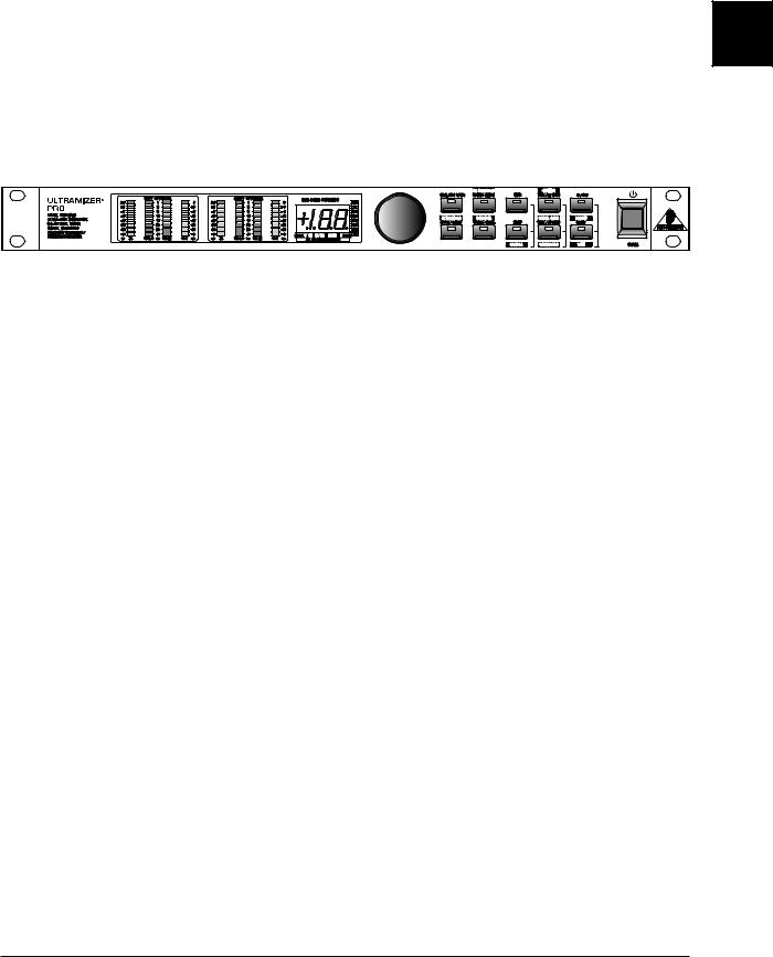
Fig. 1.1: ULTRAMIZER PRO front panel
The BEHRINGER ULTRAMIZER PRO is equipped with ten illuminated parameter keys, one jog wheel (rotary control), a numeric display, 8 LED indicators and a power switch. Each of the two fully independent channels can be monitored with four 8-stage LED meters, displaying input level, output level and gain reduction for both bands.
1.3.1 Front panel
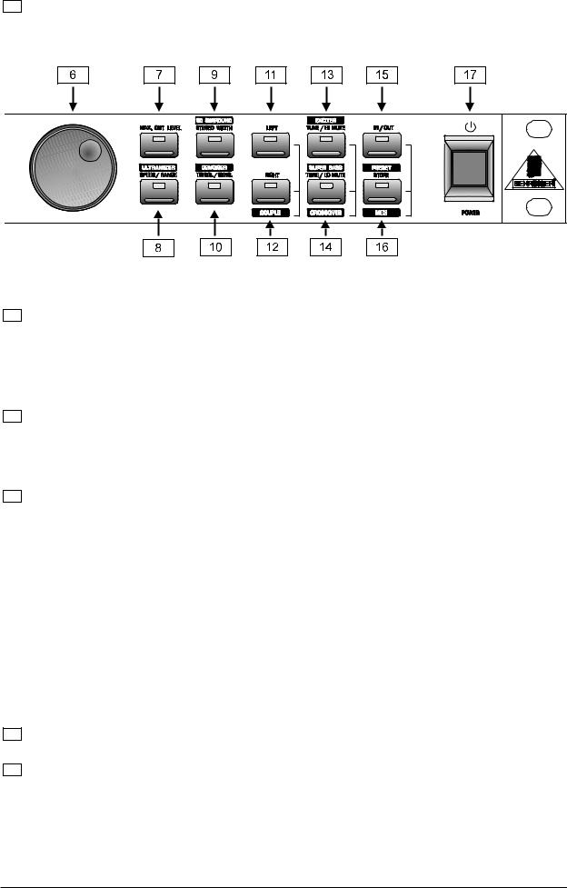
Fig. 1.2: Display section DSP1400P
1 The two LED chains read the input signal level in dB, referenced to the internal digital maximum.
+Please note that the nominal level of the ULTRAMIZER PRO can be selected with the +4 dBu / -10 dBV switch located on the back panel. (see 3.1 “Level setting”)
2The gain reduction meters show the applied gain reduction. Gain reduction is shown for both frequency bands. GR LO shows the gain reduction in the lower and GR HI in the higher frequency band.
3These two OUT LED chains read the output signal level in dB, referenced to the maximum output level of +15 dBu.
4After power-up, the LED display reads the number of the preset last used. This clearly legible, 2½ digit numeric display has plus/minus indicators to show that parameters are being incremented or decremented in Edit mode.
1. INTRODUCTION |
9 |
5Next to the display, the appropriate unit lights up to indicate the correct value which is being edited. These eight LED illuminated units are very important with keys which can represent more than one parameter.
Fig. 1.3: Function keys and jog wheel
6With the jog wheel, a continuous rotary control, you can freely edit the selected parameters. Turn the wheel clockwise to increase the values or counter-clockwise to reduce them.
+When you press the PRESET key once, you can use the wheel to select a program directly, which is shown by a dot lighting up in the display. While this dot is on, you can select a program though its settings will not take immediate effect. When the jog wheel has not been touched for a short time, the LED in the display disappears and the program is loaded.
7Use the MAX. OUT LEVEL to set the output limiter. This value can be set from -48 to 0 dB. The dB value will light up next to the numeric display. You can change the MAX. OUT LEVEL parameter from peak to RMS mode by pressing the MAX. OUT LEVEL key for about 2 seconds. RMS means the setting of an average level for the MAX. OUT LEVEL parameter. Peak stands for a peak value. To make clear that you are in RMS mode “RMS” will light up in the display.
8The Ultramizer function enables you to maximize the perceived loudness of the program material. The ULTRAMIZER key gives you access to three parameters:
a)When pressed once the DENSITY (“DENS” will light up in the display) can be adjusted. The subjectively felt density of the program material is the result of the amount of compression that is applied. The DENSITY can be adjusted from 0 (no compression) to 100 (extreme dynamic gain reduction).
b)Pressed a second time, the SPEED of the Ultramizer function can be set (“SPED” will light up in the display). This parameter is very important for the dynamic behavior which depends on the application. Generally low SPEED settings are suited if the ULTRAMIZER is to work rather “inaudibly”. Higher SPEED is required when short level changes should be levelled.
c)Pressed third time, the RANGE can be set (“dB” will light up in the display). This parameter determines the maximum amplification the Ultramizer function may use in order to achieve the desired DENSITY and MAXIMUM OUTPUT LEVEL. The value can be adjusted from 0 to 24 dB.
For further information on the Ultramizer function please refer to section 2.1.1.
9Use the 3D SURROUND key to increase the stereo width of the signal. Setting can range from 0 (no processing) to 100.
10With the DENOISER key you have access to two parameters which influence the process.
a) When pressed once the THRESHOLD of the Noise Gate can be set (“dB” will light up in the display). The value ranges from -90 dB to 0 dB. “OF” means the Denoiser function is deactivated.
+Please bear in mind that when the threshold number displayed is small, the threshold level in fact is high and consequently only loud signals will pass through. When the value is lowered to -100 dB for example (referring to the digital maximum) every signal will pass.
10 |
1. INTRODUCTION |
11
12
b) When pressed a second time the SENSITIVITY can be adjusted (“SENS” will light up in the display). This governs the sensitivity of the dynamic high cut filter and how it reacts to the input signal. The value ranges from 0 to 100.
When the LEFT key is pressed only the settings for the left channel are edited.
Use the RIGHT key to select the right audio channel.
+ If you wish to process the left and right audio channels simultaneously (COUPLE mode), press |
E |
both LEFT & RIGHT keys together. In couple mode both key LEDs light up. Whenever you edit |
|
one of the two audio channels and then switch to couple mode, the parameters of the active |
|
channel will be copied to the other; i.e. if you press LEFT before RIGHT, left will be copied to |
right.
13The EXCITER key has three functions:
a)PROCESS, (“PROC” will light up) when pressed once the intensity of the Exciter function can be adjusted ranging from 0 to 100.
b)Pressed a second time the TUNE parameter can be set (“kHz” will light up). The TUNE control sets the lower cut-off frequency of the Exciter function. The cut-off frequency can be adjusted within a range of 4 to 12 kHz.
c)The third function is reached by pressing the EXCITER key for more than 2 seconds. The upper frequency band is then muted. This is indicated by a full LED bar that flashes on and off (GR HI). This function is useful when you want to monitor the processing of the ULTRAMIZER PRO. Alternatively the unit can also be used as a crossover to generate a subwoofer signal for instance.
14The SUPER BASS key has three functions:
a)PROCESS, when pressed once the intensity of the Super Bass function can be adjusted ranging from 0 to 100 (“PROC” will light up).
b)Pressed a second time the TUNE parameter can be set (“Hz” will light up). Here the TUNE control sets the upper cut-off frequency of the Super Bass function. The cut-off frequency can be adjusted within a range of 50 to 150 Hz.
c)Again the third function is reached by pressing the SUPER BASS key for more than 2 seconds. The lower frequency band is now muted. This is indicated by a full GR LO LED bar that flashes on and off.
+When the EXCITER and SUPER BASS keys are pressed simultaneously, the crossover frequency, between – the lower and higher bands of the multiband compressor – can be adjusted from 20 Hz to 20 kHz.
15The IN/OUT key enables you to bypass the DSP1400P. The green LED lights up as soon as the ULTRAMIZER PRO is activated.
16Whenever a setting has been changed the PRESET key starts to blink slowly, indicating that a preset has been changed but not stored. When the PRESET key is pressed once the current preset number is shown in the numeric display. When the PRESET key is pressed again the current preset number starts flashing, you can then select any of the 50 memory locations. Press a third time to save the edited program to a user preset as shown in the display.
+When the IN/OUT and PRESET keys are pressed simultaneously the ULTRAMIZER PRO enters the MIDI menu, where all MIDI settings can be edited.
1. INTRODUCTION |
11 |
 Loading...