


VIRTUALIZER® PRO DSP1000P
User´s Manual
Bedienungsanleitung
Version 1.0 October 1998
E
D
www.behringer.de

EG-Declaration of Conformity
INTERNATIONALGmbH
acc. to the Directives 89/336/EWG and 73/23/EWG
We, BEHRINGER INTERNATIONAL GmbH
Hanns-Martin-Schleyer-Straße 36 - 38
D - 47877 Willich
Name and address of the manufacturer or the introducer of the product on the market who is established in the EC
herewith take the sole responsibility to confirm that the product:
VIRTUALIZER PRO DSP1000P
Type designation and, if applicable, Article-No
which refers to this declaration, is in accordance with the following standards or standardized documents:
ξ EN 60065 |
ξ EN 61000-3-2 |
ξ EN 55020 |
ξ EN 61000-3-3 |
ξ EN 55013 |
ξ EN 55022 |
The following operation conditions and installation arrangements have to be presumed:
acc. to Operating Manual
B. Nier, President |
Willich, 01.10.1998 |
Name, address, date and legally binding signature of the person responsible |
|
2

SAFETY INSTRUCTIONS
CAUTION: To reduce the risk of electrical shock, do not remove the cover (or back). No user serviceable parts inside; refer servicing to qualified personnel.
WARNING: To reduce the risk of fire or electrical shock, do not expose this appliance to rain or moisture.
This symbol, wherever it appears, alerts you to the presence of uninsulated dangerous voltage inside the enclosure - voltage that may be sufficient to constitute a risk of shock.
E
This symbol, wherever it appears, alerts you to important operating and maintenance instructions in the accompanying literature. Read the manual.
DETAILED SAFETY INSTRUCTIONS:
All the safety and operation instructions should be read before the appliance is operated.
Retain Instructions:
The safety and operating instructions should be retained for future reference.
Heed Warnings:
All warnings on the appliance and in the operating instructions should be adhered to.
Follow instructions:
All operation and user instructions should be followed.
Water and Moisture:
The appliance should not be used near water (e.g. near a bathtub, washbowl, kitchen sink, laundry tub, in a wet basement, or near a swimming pool etc.).
Ventilation:
The appliance should be situated so that its location or position does not interfere with its proper ventilation. For example, the appliance should not be situated on a bed, sofa rug, or similar surface that may block the ventilation openings, or placed in a built-in installation, such as a bookcase or cabinet that may impede the flow of air through the ventilation openings.
Heat:
The appliance should be situated away from heat sources such as radiators, heat registers, stoves, or other appliance (including amplifiers) that produce heat.
Power Source:
The appliance should be connected to a power supply only of the type described in the operating instructions or as marked on the appliance.
Grounding or Polarization:
Precautions should be taken so that the grounding or polarization means of an appliance is not defeated.
Power-Cord Protection:
Power supply cords should be routed so that they are not likely to be walked on or pinched by items placed upon or against them, paying particular attention to cords and plugs, convenience receptacles and the point where they exit from the appliance.
Cleaning:
The appliance should be cleaned only as recommended by the manufacturer.
Non-use Periods:
The power cord of the appliance should be unplugged from the outlet when left unused for a long period of time.
Object and Liquid Entry:
Care should be taken so that objects do not fall and liquids are not spilled into the enclosure through openings.
Damage Requiring Service:
The appliance should be serviced by qualified service personnel when:
-The power supply cord or the plug has been damaged; or
-Objects have fallen, or liquid has been spilled into the appliance; or
-The appliance has been exposed to rain; or
-The appliance does not appear to operate normally or exhibits a marked change in performance; or
-The appliance has been dropped, or the enclosure damaged.
Servicing:
The user should not attempt to service the appliance beyond that is described in the Operating Instructions. All other servicing should be referred to qualified service personnel.
3

VIRTUALIZER PRO
Ultra-high performance Digital Multi-Effects Processor powered by a 24-bit high-speed Digital Signal Processor (DSP)
s“Wave Adaptive Virtual Room” reverb algorithms calculated from precise mathematical roomDSP1000Pmodels to give you ultra-natural reverb effects
s32 breathtaking Reverb, Chorus, Flanger, Delay (10 sec.), Pitch Shifter, Vocoder, Rotary Speaker effects and more
sMore than 700 effects variations plus two individual parameters and separate low and high EQ section
sTwo digital processing engines give you independent or coupled effects on left and right channels
sTrue stereo processing performance allows separation of left and right channels in the stereo field for open-sounding enhancement of the sound sources
sFree VIRTUALIZER DESIGN software allows for total remote control via PC (download at www.behringer.de)
s20-bit A/D and D/A converters with 64/128 times oversampling for ultra-high headroom and resolution
sInternal 24-bit processing with professional 46 kHz sampling rate
sServo balanced Inputs and Outputs on gold plated XLR and TRS jack connectors for high signal integrity
s100 user preset memories to store programs for instant recall
sAccurate eight-segment LED level meters simplify level setting for optimum performance
s“Future-proof” software-upgradeable architecture
sFull MIDI capability allows real-time parameter control and program selection
sHigh-quality components and exceptionally rugged construction ensures long life and durability
sInternal power supply design for professional application
sManufactured under the ISO9000 management system
4

FOREWORD
Dear Customer,
Welcome to the team of VIRTUALIZER PRO users and thank you very much for expressing your confidence in |
|
BEHRINGER products by purchasing this unit. |
E |
It is one of my most pleasant tasks to write this letter to you, because it is the culmination of many months of |
|
hard work delivered by our engineering team to reach a very ambitious goal: making an outstanding device |
|
better still. The VIRTUALIZER DSP1000 has for quite a long time been a standard tool used by numerous |
|
|
|
studios and P.A. rental companies. The task to improve one of our best-selling products certainly meant a |
|
great deal of responsibility, which we assumed by focusing on you, the discerning user and musician. It also |
|
meant a lot of work and night shifts to accomplish this goal. But it was fun, too. Developing a product usually |
|
brings a lot of people together, and what a great feeling it is when everybody who participated in such a project |
|
can be proud of what we’ve achieved. |
|
It is our philosophy to share our joy with you, because you are the most important member of the BEHRINGER |
|
family. With your highly competent suggestions for new products you’ve greatly contributed to shaping our |
|
company and making it successful. In return, we guarantee you uncompromising quality (manufactured under |
|
ISO9000 certified management system) as well as excellent technical and audio properties at an extremely |
|
favorable price. All of this will enable you to fully unfold your creativity without being hampered by budget |
|
constraints. |
|
We are often asked how we can make it to produce such high-grade devices at such unbelievably low prices. |
|
The answer is quite simple: it’s you, our customers! Many satisfied customers means large sales volumes |
|
enabling us to get better conditions of purchase for components, etc. Isn’t it only fair to pass this benefit back |
|
to you? Because we know that your success is our success, too! |
|
I would like to thank all people whose help on “Project VIRTUALIZER PRO” has made it all possible. Everybody |
|
has made very personal contributions, starting from the designers of the unit via the many staff members in our |
|
company to you, the user of BEHRINGER products. |
|
My friends, it’s been worth the trouble!
Thank you very much,
Uli Behringer
5

TABLE OF CONTENTS |
|
|
1. INTRODUCTION ...................................................................................................................... |
7 |
|
1.1 |
The Design Concept ....................................................................................................................... |
7 |
1.2 |
Before you begin ............................................................................................................................ |
8 |
1.3 |
Control elements ............................................................................................................................. |
8 |
1.4 |
The effect algorithms ..................................................................................................................... |
11 |
|
1.4.1 Reverb and delay algorithms ............................................................................................... |
12 |
|
1.4.2 Special effects .................................................................................................................... |
13 |
|
1.4.3 Modulation and pitch shifter effects .................................................................................... |
13 |
|
1.4.4 Effect algorithm combinations (multi-effects programs) ...................................................... |
14 |
|
1.4.5 Dual-mode effects algorithms ............................................................................................. |
14 |
2. OPERATION ........................................................................................................................... |
16 |
|
2.1 |
Effects structure ........................................................................................................................... |
16 |
2.2 |
Selecting presets .......................................................................................................................... |
16 |
2.3 |
Editing programs .......................................................................................................................... |
17 |
2.4 |
Saving programs ........................................................................................................................... |
17 |
2.5 |
MIDI control .................................................................................................................................. |
17 |
3. APPLICATIONS ..................................................................................................................... |
19 |
|
3.1 |
Level setting .................................................................................................................................. |
19 |
3.2 |
Using the VIRTUALIZER PRO in the aux bus ................................................................................ |
19 |
3.3 |
Using the VIRTUALIZER PRO in the insert path ............................................................................ |
20 |
3.4 |
Using the VIRTUALIZER PRO as an effects device for instruments .............................................. |
21 |
3.5 |
Using the VIRTUALIZER PRO in a MIDI system ........................................................................... |
22 |
3.6 |
Saving data via MIDI ..................................................................................................................... |
22 |
4. TECHNICAL BACKGROUND ................................................................................................ |
22 |
|
4.1 |
Digital Audio Processing ............................................................................................................... |
22 |
4.2 |
Reverberation and reflection ......................................................................................................... |
24 |
|
4.2.1 Reverberation chambers ..................................................................................................... |
25 |
|
4.2.2 Spring and plate reverb ....................................................................................................... |
25 |
|
4.2.3 Digital reverb ...................................................................................................................... |
26 |
5. INSTALLATION ...................................................................................................................... |
27 |
|
5.1 |
Rack mounting .............................................................................................................................. |
27 |
5.2 |
Mains connection.......................................................................................................................... |
27 |
5.3 |
Audio connections ........................................................................................................................ |
27 |
5.4 |
MIDI connections.......................................................................................................................... |
29 |
5.5 |
Operating Level switch .................................................................................................................. |
29 |
6. APPENDIX ............................................................................................................................. |
30 |
|
6.1 |
Parameter overview ...................................................................................................................... |
30 |
6.2 |
Delay values / increments for presets 10 and 11.......................................................................... |
31 |
6.3 |
MIDI-implementation ..................................................................................................................... |
32 |
6.4 |
Default settings ............................................................................................................................. |
33 |
6.5 |
Specifications ............................................................................................................................... |
34 |
7. WARRANTY .......................................................................................................................... |
35 |
|
6

1. INTRODUCTION
The BEHRINGER VIRTUALIZER PRO is a member of the latest generation of multi-effects processors. To generate reverberation that is very natural in character, we at BEHRINGER developed innovative virtual acoustics algorithms which allow for computing all room and reverb parameters with absolute pro-level quality and a highly natural sound character.
Since its introduction in the early 80’s, artificial digital reverb has been an indispensable standard tool for studio |
E |
and live applications. Before, professional reverberation could only be produced by using bulky and expensive |
|
reverberation plates. With the rapid development of digital technology it has become possible to drastically |
|
reduce the price of a good reverb unit, so it is anything but unusual today to find at least one digital reverb |
|
device in the racks of P.A. rental companies and recording studios. Owing to their system structure, most |
|
digital effects processors are also capable of generating other effects in addition to reverberation. These multi- |
|
effects processors enable the user to easily produce a maximum variety of effects featuring pro-level audio |
|
quality. |
|
With the BEHRINGER VIRTUALIZER PRO you have purchased a very powerful multi-effects processor which offers both first-class reverb sounds and various other effect algorithms. Although you will find a high number of effect types - 32 newly developed effect types with more than 700 variations - the VIRTUALIZER PRO can be operated easily and intuitively with its logically structured user interface. The VIRTUALIZER PRO gives you well-known classic effects such as reverb, delay and chorus, plus a broad spectrum of additional programs including such extraordinary effects as "Vocal Distortion", "Rotary Speaker Simulation" or "Vocoder". To be able to fully exploit these effects as well as the other features of the BEHRINGER VIRTUALIZER PRO’s innovative virtual acoustics technology, we recommend that you read this user’s manual carefully.
+The following operational manual will introduce you to the BEHRINGER VIRTUALIZER PRO and its various functions. After reading the manual carefully, make sure it is always on hand for future reference.
1.1 The Design Concept
Despite extensive computing work which is done in the DSP1000P by a “dual-engine” 24-bit processor, the VIRTUALIZER PRO can be operated easily and conveniently. All parameter edits are performed with the jog wheel (rotary control). 100 presets are available to store user-defined programs.
However, the DSP1000P is by no means limited to excellent reverb and delay programs. In addition to the simulation of classic plate reverbs, the VIRTUALIZER PRO gives you extraordinary modulation effects (such as chorus and flanger), plus a few special-purpose variants, e.g. a musical pitch shifter as well as tremolo and rotary speaker simulations. With the vocoder and vocal distortion effect programs, you even have ultra-modern effects available that the DSP1000P generates with absolute realism.
A very special feature are the high-low filters which can be freely edited and directly selected in each preset. With these filters you can fine-tune the sound of your presets to match any given room characteristics - a time saving feature especially for live applications, where every second counts. The VIRTUALIZER PRO not only features a logical and easy-to-operate user interface but also highly impressive specifications. With its complete MIDI implementation the DSP1000P can be integrated in any MIDI system. A MIDI software editor (soon available) enables you to program the VIRTUALIZER PRO from your personal computer, and the MIDI interface allows for transmitting data from the DSP1000P and store them on an external storage medium. For example, you can use sys-ex dumps to send all presets and settings to your sequencer program and reload them from there whenever you want.
The philosophy behind BEHRINGER products guarantees a no-compromise circuit design and employs the best choice of components. Top-quality 20-bit AD/DA converters which belong to the best components available owing to its outstanding specifications and excellent sonic characteristics. Two 24-bit DSPs are used as the heart of the VIRTUALIZER PRO. These perform the precise calculations needed for the processing of the complex algorithms. Additionally, the VIRTUALIZER PRO uses high quality resistors and capacitors with very tight tolerances, high-grade switches, low-noise operational amplifiers (type 4580) as well other selected components
The VIRTUALIZER PRO DSP1000P uses SMD technology (Surface Mounted Device). These subminiature components known from aerospace technology allow for an extreme packing density, plus the unit’s reliability could be improved. Additionally, the unit is manufactured in compliance with a ISO9000 certified management
1. INTRODUCTION |
7 |
system.
1.2 Before you begin
Your BEHRINGER VIRTUALIZER PRO was carefully packed in the factory and the packaging was designed to protect the unit from rough handling. Nevertheless, we recommend that you carefully examine the packaging and its contents for any signs of physical damage, which may have occurred in transit.
+If the unit is damaged, please do not return it to us, but notify your dealer and the shipping company immediately, otherwise claims for damage or replacement may not be granted. Shipping claims must be made by the consignee.
The BEHRINGER VIRTUALIZER PRO fits into one standard 19" rack unit of space (1 3/4"). Please allow at least an additional 4" depth for the connectors on the back panel.
+Be sure that there is enough space around the unit for cooling and please do not place the VIRTUALIZER PRO on high temperature devices such as power amplifiers etc. to avoid overheating.
The mains connection of the VIRTUALIZER PRO is made by using a mains cable and a standard IEC receptacle. It meets all of the international safety certification requirements. Please make sure that all units have a proper ground connection.
+Before you connect your VIRTUALIZER PRO to the mains, please make sure that your local voltage matches the voltage required by the unit! (see chapter 5 for details)
+Please ensure that only qualified persons install and operate the VIRTUALIZER PRO. During installation and operation the user must have sufficient electrical contact to earth. Electrostatic charges might affect the operation of the VIRTUALIZER PRO!
As a standard the audio inputs and outputs on the BEHRINGER VIRTUALIZER PRO are fully balanced. If possible, connect the unit to other devices in a balanced configuration to allow for maximum interference immunity. The automatic servo function detects unbalanced connections and compensates the level difference automatically (6 dB correction).
The MIDI links (IN/OUT/THRU) are made over standardized DIN patch cords. The data communication is isolated from ground by opto-couplers.
1.3 Control elements
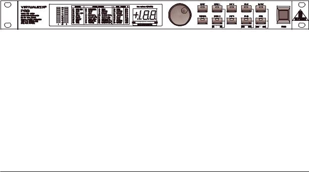
Fig. 1.1: VIRTUALIZER PRO front panel
The BEHRINGER VIRTUALIZER PRO is equipped with ten parameter keys, one jog wheel (rotary control), an LED display and a power switch. Each of the two fully independent channels can be monitored with an 8-stage LED meter.
8 |
1. INTRODUCTION |

E
Fig. 1.2: Display section of the DSP1000P
1 The two LED chains display the input signal level in dB, referenced to the internal digital maximum.
+Please note that the nominal level of the VIRTUALIZER PRO can be selected with the +4 dBu / -10 dBV switch located on the back panel.
2The EFFECT TABLE gives you an overview of the 32 different effect algorithms.
3After power-up, the LED display shows the number of the preset last used. This clearly legible, 2½ digit numeric display has plus/minus indicators to show that parameters are being incremented or decremented in Edit mode.
Fig. 1.3: Function keys and jog wheel
4With the JOG WHEEL, a continuous rotary control, you can freely edit the selected parameters. Turn the wheel clockwise to increase the values, or counterclockwise to reduce them.
+As long as none of the edit functions to the right of the jog wheel have been selected, you can use the wheel to select a program directly, which is shown by a dot lit up in the display. While this dot is on, you can select a program though its settings will not take immediate effect. When the jog wheel has not been touched for at least one second, the LED in the display disappears and the program will be loaded.
5 Use the EFFECT key to directly select one of the 32 basic effect algorithms with the jog wheel.
+Whenever a new algorithm is selected, all parameters are reset to default values. See table 6.4 in the appendix.
1. INTRODUCTION |
9 |

6The VARIATION key allows you to select an alternative variation of each effect algorithm activating a different setup of the numerous internal effect parameters. With this feature you can extensively manipulate the effect sound within a very wide range.
7Use the ENGINE L key to select the left audio channel for true-stereo effects. Many effects may have different ENGINE L and ENGINE R parameters available through EDIT A and EDIT B. Where to find which parameter can be seen from the parameter list printed on the top of the unit.
8Use the ENGINE R key to select the right audio channel (similar to point 7: ENGINE L). If you wish to process the left and right audio channels simultaneously (COUPLE mode), press both Engine keys together. In COUPLE mode both Engine LEDs light up. Whenever you edit one of the two audio channels and then switch to COUPLE mode, the parameters of the active channel will be copied to the other; i.e if you press ENGINE L before R, left will be copied to right. When parameters cannot be adjusted separately in a specific algorithm, the DSP1000P switches to COUPLE mode automatically.
9In each preset you can edit at least two parameters in addition to the preset variation. Use the EDIT A key to select the first parameter. The exact parameter assignment can be seen from the parameter list printed on top of the unit.
10The EDIT B key allows you to modify the second parameter as required.
11To give your programs the finishing touch, the VIRTUALIZER PRO incorporates two filters. Use the EQHI key to raise or lower the high-frequency portions of the effect program.
12The EQ-LO key activates a filter which processes the low-frequency portions of your preset.
13The IN/OUT key enables you to bypass the DSP1000P. The green LED lights up as soon as the VIRTUALIZER PRO is activated. Depending on the Mix mode adjusted (see below), this key can also be used to activate the Mute function. Additionally, the green LED starts flashing whenever MIDI data are being received.
14Use the STORE key to save the edited program to a user preset as shown in the display. 100 user presets are available on the DSP1000P. Press the key once to select a memory location (number), then press it again to store the preset.
15Use the POWER switch to switch the VIRTUALIZER PRO on or off.
Key combinations
To protect the DSP1000P against user errors, three important edit commands have been implemented as a series of key combinations. For example, in normal operating modes, the presets cannot be reset to their factory defaults, so as to secure your own programs as safely as possible. Please proceed as follows to reinitialize the preset default settings:
sKeep the keys EFFECT and STORE pressed before powering up the VIRTUALIZER PRO. Then switch on the DSP1000P and keep the two keys pressed for about two seconds. The program numbers are counted up and reset to their original default settings.
The VIRTUALIZER PRO provides two methods to mix the input and the effect signals (External Mix and Internal Mix modes). Select External Mix mode to use the DSP1000P with a mixing console: in this mode all presets are set to 100% effect intensity, i.e. you can use the aux return busses of your console to add the processed signal to the original signal. In External Mix mode the IN/OUT key is used to bypass the unit. Here’s how to enter External Mix mode:
sWith the unit switched on, press the Mix mode key combination, i.e. the keys EQ LO and EQ HI. The VIRTUALIZER PRO enters Mix mode. When the display shows two dashes, the DSP1000P is in External Mix mode, and when a figure is displayed, Internal Mix mode is selected. To toggle between the two modes, simply press both EQ keys for about 2 seconds.
In Internal Mix mode you can use the jog wheel to freely select the effect intensity in each preset within a range from 0% to 100%, a highly useful feature, for instance, to insert the DSP1000P in the effect loop of a guitar amp. Good results can be achieved with settings between 20% and 50%.
Another key combination can be used to enter MIDI mode. With the VIRTUALIZER PRO switched on, proceed as follows:
sKeep the keys IN/OUT and STORE pressed for about two seconds, the DSP1000P automatically enters MIDI mode. Use the IN/OUT key to step through the various MIDI parameters. Press
10 |
1. INTRODUCTION |
any other key to quit MIDI mode.
E
Fig. 1.4.: Back panel connectors and control elements
16Use the OPERATING LEVEL switch to adapt the VIRTUALIZER PRO to different operating levels. You can select a -10 dBV semi-pro level used for home recording and a +4 dBu level used in professional studios. The level indicators on the front panel are automatically adapted to read the selected nominal level, i.e. an optimum operating range of the meters is always guaranteed.
17These are the VIRTUALIZER PRO’s analog INPUTS. The VIRTUALIZER PRO has both XLR and jack inputs and outputs. Each XLR and jack set are wired parallel and can be used either balanced and unbalanced.
18These are the VIRTUALIZER PRO’s analog OUTPUTS. Also on balanced or unbalanced XLR or TRS jacks.
19These are the VIRTUALIZER PRO’s MIDI connectors (MIDI OUT / THRU / IN). Total remote control is possible via MIDI.
20Please take the time to make a note of the SERIAL NUMBER in the space provided on the enclosed Warranty Registration Card. Put the instruction manual in a safe place and return the completed Warranty Registration Card to us within 14 days of purchase, making sure that the dealer stamp has been acquired (certain countries only).
21This is the MAINS CONNECTOR / FUSE HOLDER / VOLTAGE SELECTOR. Before you connect the unit, please make sure that the displayed voltage corresponds to your Mains supply. Please note that the AC voltage selection is defined by the position of the Fuse Holder. If you intend to change the operating voltage, remove the Fuse Holder and turn it by 180 degrees before you reinsert it. Matching the two markers monitors the selected voltage. Please note that, depending on the mains voltage supplied to the unit, the correct fuse type and rate must be installed (see chapter 6.5 “SPECIFICATIONS”’). Please use the enclosed mains cable to connect the unit to the mains power supply.
+Please note that not all appliances can be used with different mains voltage ratings. Please check the description on the back of the unit and the box.
1.4 The effect algorithms
In a digital effects device all effect programs are based on algorithms computed by a Digital Signal Processor (DSP). How does this work? A DSP can perform an enormous number of binary computations in a minimum amount of time. The binary computations used to generate an effect as part of a program are determined by a so-called algorithm which represents a rule for computing numerical values that are exactly specified for each effect type. For example, reverb algorithms differ from chorus algorithms in their programming. Plainly speaking: each effect is based on a specific algorithm which processes the input signal (converted from analog to digital before). All of this work is done by the DSP. Once the effect has been generated and added to the input signal, the digital music signal is converted back to analog by means of a D/A converter.
The VIRTUALIZER PRO permits the change of as many as five parameters which influence the sound in different ways. This means that for some algorithms the parameters are chosen by using key combinations with ENGINE L and ENGINE R. In these cases a combination of ENGINE L and ENGINE R with the EDIT A and EDIT B key will not mean that only one channel is affected. The combination EDIT A – ENGINE L is a different parameter than the combination EDIT A – ENGINE R, these parameters will be changed on both channels. With a reverb effect (like PRG 1) Edit B – ENGINE R does not mean that the right audio channel is processed, but that the second Edit B parameter (with Prg.1: High Multiply) is adjusted.
The only exception is the DUAL MONO (PARALLEL) effects, which produce another effect in the left channel
1. INTRODUCTION |
11 |
 Loading...