

Page 1
Installation and Operating Manual for
C9900-G0xx
Push-Button Extension for Multi-Touch Control Panel
- CP2xxx
- CP39xx
Version: 1.2
Date: 2014-12-12
Page 2

Page 3

Table of contents
Table of contents
1 Foreword 3
1.1 Notes on the documentation 3
1.1.1 Disclaimer 3
1.1.2 Brands 3
1.1.3 Patents 3
1.1.4 Copyright 3
1.1.5 Delivery state 3
1.1.6 Delivery conditions 3
1.2 Description of safety symbols 4
1.3 Basic safety measures 5
1.4 Operator's obligation to exercise diligence 6
1.4.1 National regulations 6
1.4.2 Procedure in the event of a fault 6
1.4.3 Operator requirements 6
2 Product description 7
2.1 Product overview 7
2.2 Intended use 8
2.3 Accessing the connections 8
2.3.1 CP2xxx 8
2.3.2 CP39xx without mounting arm adapter 9
2.3.3 CP39xx with mounting arm adapter 10
2.4 Connections 11
2.4.1 Description of the PCBs 11
2.4.2 Configuration 14
2.4.3 Toggle switch 15
2.5 Wiring of the connection strips 15
2.6 Inserting self-printed labels 16
3 Special instructions for the TwinCAT System Manager 17
3.1 From TwinCAT 2.11 build 2245 18
4 Installation 19
4.1 Transport and unpacking 19
4.1.1 Transport 19
4.1.2 Unpacking 19
4.2 Connecting the push-button extension 20
4.2.1 Connecting cables 20
5 Operation 21
C9900-G0xx 1
Page 4

Table of contents
5.1 Maintenance 21
5.1.1 Cleaning 21
5.1.2 Maintenance 21
5.2 Emergency procedures 21
5.3 Decommissioning 21
5.3.1 Disposal 21
6 Technical data 22
7 Appendix 23
7.1 Service and support 23
7.1.1 Beckhoff's branch offices and representatives 23
7.2 Headquarters 23
7.2.1 Beckhoff Service 23
7.2.2 Beckhoff Support 23
7.3 PCBs used in keyboard extensions 24
7.4 Circuit diagrams 25
7.4.1 Circuit diagram for emergency off PCB 25
7.4.2 Circuit diagram for three-button PCB 26
7.4.3 Circuit diagram for four-button PCB 27
7.5 FCC certifications for the United States of America 28
7.6 FCC certifications for Canada 28
2 C9900-G0xx
Page 5

Foreword
1 Foreword
1.1 Notes on the documentation
This description is only intended for the use of trained specialists in control and automation technology
familiar with the applicable national standards.
It is essential that the following notes and explanations are followed when installing and commissioning
these components. The responsible staff must ensure that the application or use of the products
described satisfy all the safety requirements, including all the relevant laws, regulations, guidelines and
standards.
1.1.1 Disclaimer
This documentation has been prepared with care. The products described are, however, constantly under
development. For this reason, the documentation may not always have been fully checked for
consistency with the performance data, standards or other characteristics described. If it should contain
technical or editorial errors, we reserve the right to make changes at any time and without notice. No
claims for the modification of products that have already been supplied may be made on the basis of the
data, diagrams and descriptions in this documentation.
1.1.2 Brands
Beckhoff®, TwinCAT®, EtherCAT®, Safety over EtherCAT®, TwinSAFE® and XFC® are registered
trademarks of and licensed by Beckhoff Automation GmbH.
The use by third parties of other brand names or trademarks contained in this documentation may lead to
an infringement of the rights of the respective trademark owner.
1.1.3 Patents
The EtherCAT technology is patent protected, in particular by the following applications and patents:
EP1590927, EP1789857, DE102004044764, DE102007017835 with the corresponding applications and
registrations in various other countries.
The TwinCAT technology is patent protected, in particular by the following applications and patents:
EP0851348, US6167425 with the corresponding applications and registrations in various other countries.
1.1.4 Copyright
©
Beckhoff Automation GmbH.
The copying, distribution and utilization of this document as well as the communication of its contents to
others without express authorization is prohibited. Offenders shall be held liable for damages. All rights
conferred by patent grant or registration of a utility model or registered design are reserved.
1.1.5 Delivery state
All the components are supplied in particular hardware and software configurations appropriate for the
application. Modifications to hardware or software configurations other than those described in the
documentation are not permitted, and nullify the liability of Beckhoff Automation GmbH.
1.1.6 Delivery conditions
In addition, the general delivery conditions of the company Beckhoff Automation GmbH apply.
C9900-G0xx 3
Page 6
Foreword
1.2 Description of safety symbols
The following safety symbols are used in these operating instructions. They are intended to alert the
reader to the associated safety instructions.
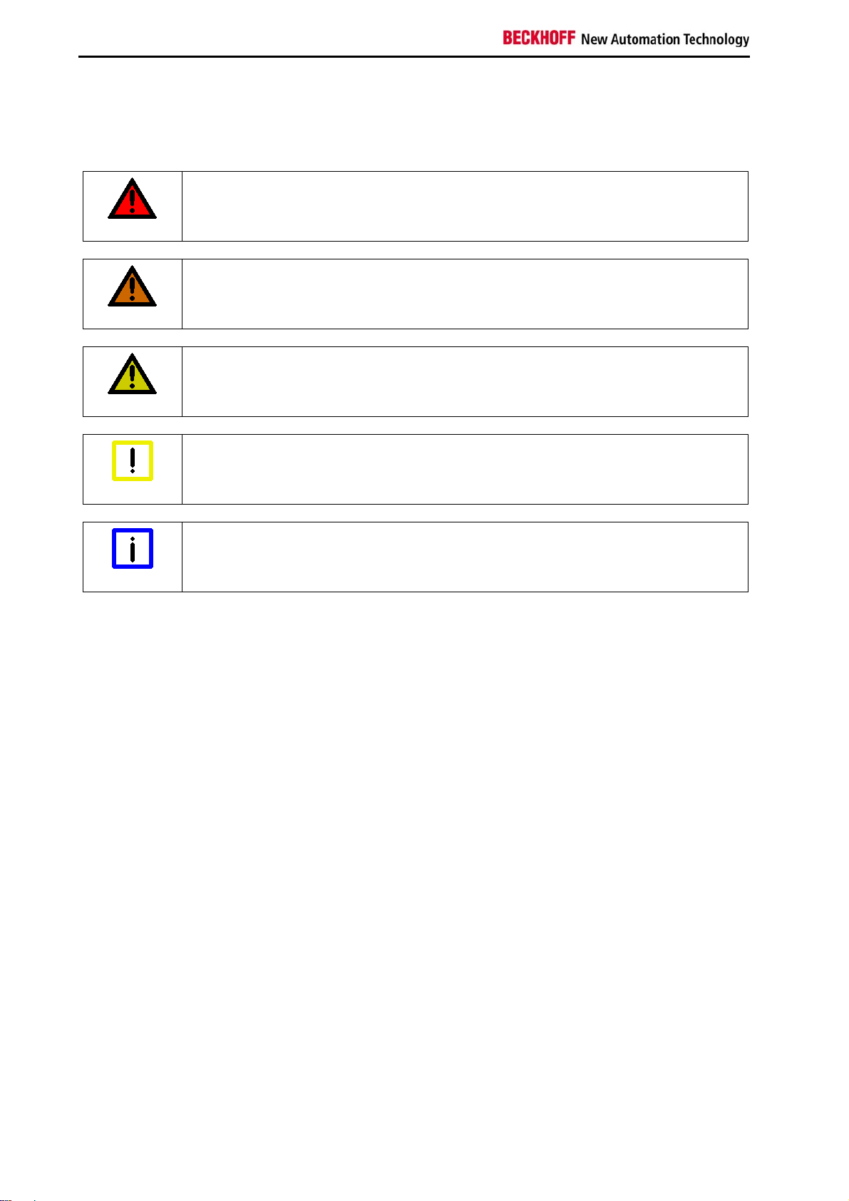
Serious risk of injury!
Failure to follow the safety instructions associated with this symbol directly endangers
DANGER
WARNING
CAUTION
the life and health of persons.
Caution - Risk of injury!
Failure to follow the safety instructions associated with this symbol endangers the life
and health of persons.
Personal injuries!
Failure to follow the safety instructions associated with this symbol can lead to injuries
to persons.
Damage to the environment or devices
Attention
Note
Failure to follow the instructions associated with this symbol can lead to damage to the
environment or equipment.
Tip or pointer
This symbol indicates information that contributes to better understanding.
4 C9900-G0xx
Page 7
Foreword
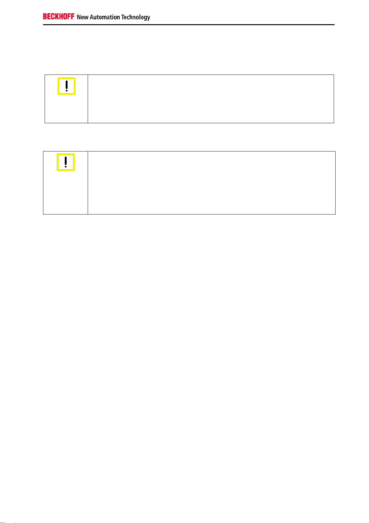
1.3 Basic safety measures
Before the Industrial PC is switched off, software that is running must be properly closed. Otherwise data
can get lost.
Switch off system components and disconnect the Control Panel from the
system
Attention
Disconnect the Control Panel by releasing the connectors at the back. System components that have
been switched off must be secured against being switched on again.
Attention
Before opening the housing, and whenever the control panel is not being used for
control purposes (such as during functional checks after a repair), all parts of the
equipment must first be switched off, after which the control panel is to be
disconnected from the equipment.
Do not exchange any parts when under power
When components are being fitted or removed, the supply voltage must be switched
off.
Assembly work can cause damage:
if metal objects such as screws or tools fall onto operating circuit boards.
if cables are connected or disconnected during operation.
C9900-G0xx 5
Page 8

Foreword
1.4 Operator's obligation to exercise diligence
The operator must ensure that
the products are only used as intended (see Product description chapter);
the products are only operated in sound condition and functioning properly.
the products are operated only by suitably qualified and authorized personnel.
the personnel is instructed regularly about relevant occupational safety and environmental
protection aspects, and is familiar with the operating instructions and in particular the safety
instructions contained herein.
the instruction manual is in good condition and complete, and always available for reference at
the location where the products are used.
1.4.1 National regulations
Depending on the type of machine and plant in which the product is used, national regulations governing
the controllers of such machines will apply, and must be observed by the operator. These regulations
cover, amongst other things, the intervals between inspections of the controller. The operator must initiate
such inspections in good time.
1.4.2 Procedure in the event of a fault
In the event of product malfunctions please contact Headquarters
Beckhoff Automation GmbH
Eiserstraße 5
33415 Verl
Germany
Phone: + 49 (0) 5246/963-0
Fax: + 49 (0) 5246/963-198
E-mail: info@beckhoff.de
Beckhoff Service.
1.4.3 Operator requirements
All users of the product must have read the operating instructions and be aware of all the functions they
can access.
6 C9900-G0xx
Page 9
Product description
2 Product description
2.1 Product overview
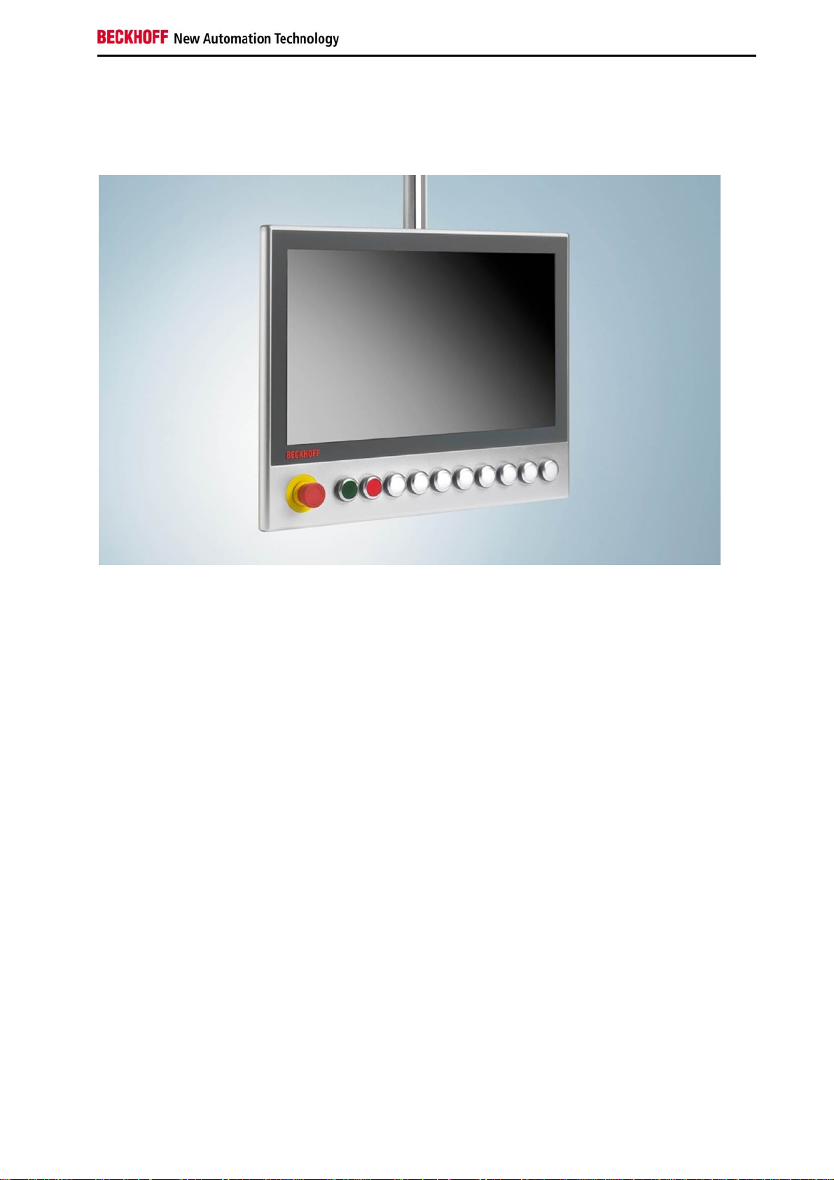
Fig. 1: CP3918 with push-button extension C9900-G025 (one emergency stop button, ten illuminated
push buttons)
The optional C990-G0xx push-button extensions for the Control Panels CP2xxx and CP39xx from
Beckhoff Automation provide additional input options. Push-button extensions that match the design of
the Control Panels enable application-specific use of electromechanical buttons. Selection and key
switches can also be integrated. The push-button extension is located below the touchscreen. The
number of buttons that can be added depends on the display size.
The actuation of the emergency stop and other buttons is transferred to the controller via USB and can be
read with TwinCAT. Optionally, customers may use the signals for additional purposes. The emergency
stop has two N/C contacts and one N/O contact. The signal of the N/O contact is transferred to the
controller. The two N/C contacts can be used by the customer. One button actuates two N/O contacts,
one of which is available as a potential-free contact for use by the customer. The indicator lamps are
controlled via USB.
By default the first button is supplied with a green cap, the second with a red cap, and the other buttons
with white caps (see Fig. 1). Other button cap color options are available for retrofitting:
C9900-Z255: 5 button caps (blue)
C9900-Z256: 5 button caps (yellow)
C9900-Z257: 5 button caps (green)
C9900-Z258: 5 button caps (red)
C9900-Z259: 5 button caps (white)
A label sheet with 54 pre-punched button labels is available under order code C9900-Z260. Application of
the labels is explained in section 2.6.
Custom adaptations are possible on request.
C9900-G0xx 7
Page 10

Product description
2.2 Intended use
The multi-touch Control Panels CP2xxx and CP39xx with push-button extension C9900-G0xx are
designed for industrial machine and systems engineering applications. The push-button extension is
located below the touchscreen.
Risk of explosion!
The Control Panels must not be used in potentially explosive atmospheres.
DANGER
2.3 Accessing the connections
The push-button extension connections for use by the customer are located at the rear of the housing. To
access the connections remove the cover panel at the rear. The exact procedure depends on the housing
type and mounting arm.
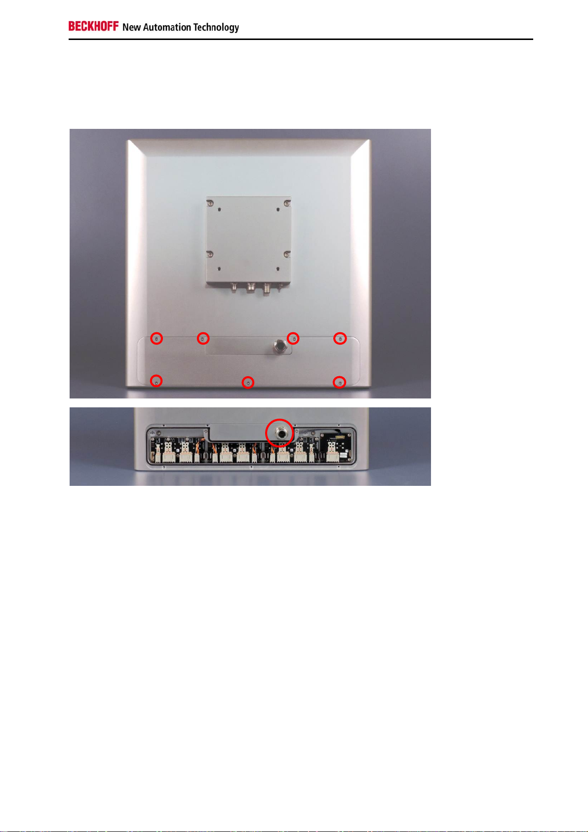
2.3.1 CP2xxx
Release the M3 screws around the perimeter of the button cover (see Fig. 2) and remove the cover. The
number of screws may vary, depending on the display size. The potential-free contacts are now
accessible. The cabling can be fed out of the housing via the M20 cable gland shown in Fig. 2. Attach the
button cover and secure it with the screws.
Fig. 2: CP2924-0000-G007 with or without button cover
8 C9900-G0xx
Page 11
Product description
2.3.2 CP39xx without mounting arm adapter
Release the M3 screws around the perimeter of the button cover (see Fig. 3) and remove the cover. The
number of screws may vary, depending on the display size. The potential-free contacts are now
accessible. The cabling can be fed out of the housing via the M20 cable gland. Attach the button cover
and secure it with the screws.
Fig. 3: CP3919-0000-G026 with or without button cover
C9900-G0xx 9
Page 12

Product description
②
②
2.3.3 CP39xx with mounting arm adapter
For Control Panels with mounting arm adapter (C9900-M752 and C9900-M753), release the M3 screws
(labelled 1 in Fig. 4) around the perimeter of the button cover and release it. Release the screws labelled
2 in Fig. 4 and remove the cover. Then remove the cover panel (3). The cover panel can easily be
levered off with a suitable tool to enable access to the connections. The potential-free contacts are now
accessible. The cabling can be guided into the mounting arm adapter through the cable channel and M20
gland shown in Fig. 5. Re-assemble the button cover and the cover panel in reverse order.
③
①
Fig. 4: CP3919-0000-G023-M752
Fig. 5: CP3919-0000-G023-M752 without button cover and cover panel
10 C9900-G0xx
Page 13
Product description
2.4 Connections
2.4.1 Description of the PCBs
This section describes and explains the PCBs for the buttons and their connections. Each PCB has
connection strips to enable customers to use the buttons and the emergency stop. The pin assignment of
the connection strips is shown on each PCB. The circuit diagrams for each of the three PCBs used can
be found in the annex under section 7.4. The connector designations (CONxxx) used in this description
refer to these circuit diagrams.
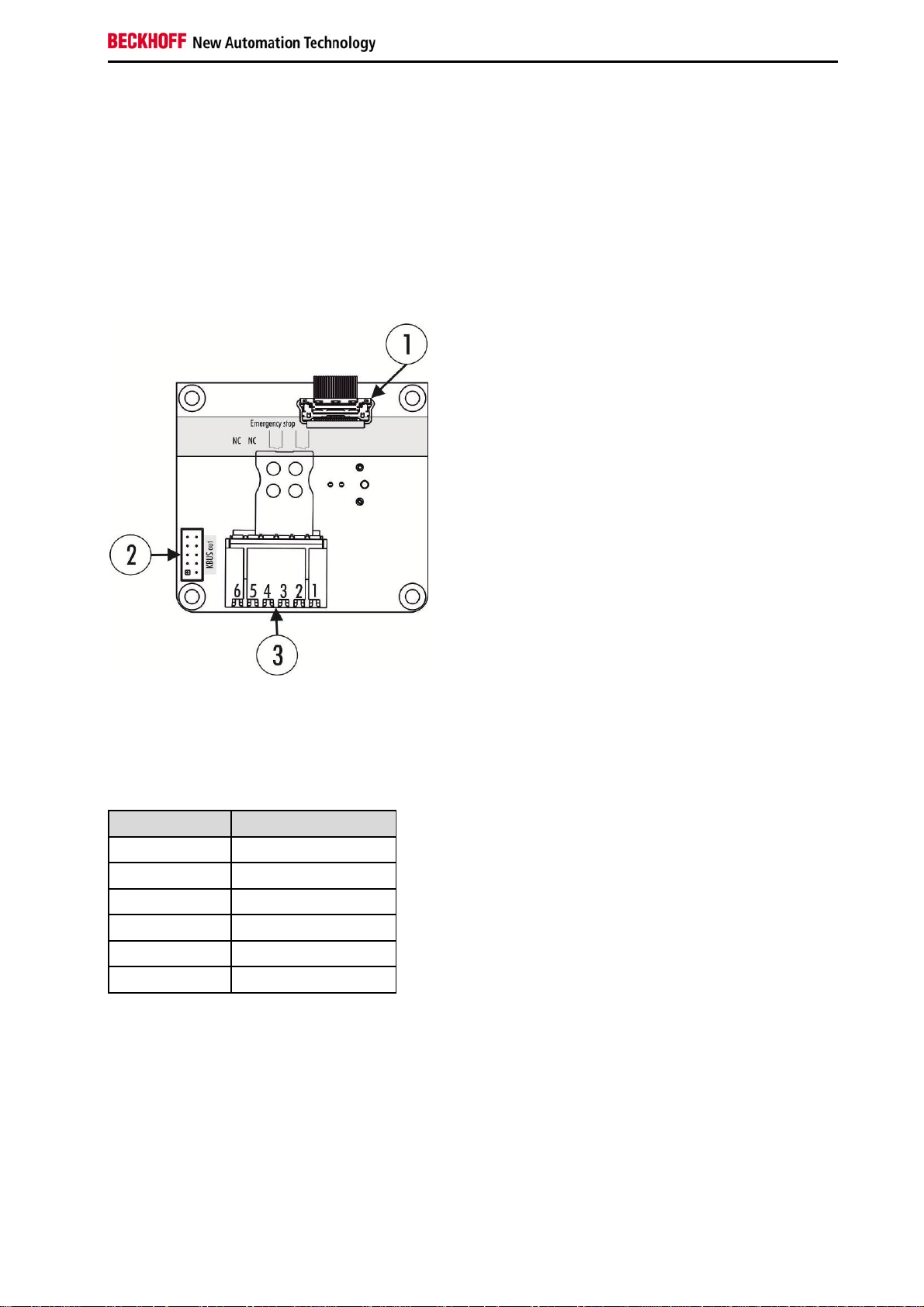
Emergency stop PCB
Fig. 6: Emergency stop PCB
The emergency stop PCB has a USB (1, CON500) and a K-bus interface (2, CON400). Both interfaces
are used for signal transfer and are assigned ex factory. A further connection strip (3, CON402) is
available for customer use via the two additional N/C contacts of the emergency stop. The connection
strip assignment is shown in Table 1.
Terminal point Description
1 Input N/C contact 1
2 Output N/C contact 1
3 Input N/C contact 2
4 Output N/C contact 2
5 Not used
6 Not used
Table 1: Pin assignment for emergency stop PCB
C9900-G0xx 11
Page 14

Product description
Three-button PCB
Fig. 7: Three-button PCB
The three-button PCB has two K-bus interfaces (1, CON400 & CON401), which are assigned ex factory.
The outer connection strips (2, CON600 & CON601) are used for power supply for the indicator lamps,
connection strip 4 is available for customer use. The bridges between the button PCBs are assigned ex
factory. The power supply has to be provided by the customer. One of the two N/O contacts of each
button is available for customer use via a connection strip (3, CON603). At a further connection strip (4,
CON602) three digital inputs are available for customer use, which are transferred via the K-bus. The 24
V supply has to be provided by the customer. The PCB also features a DIP switch (5, SW600), which is
explained in section 2.5.
The pin assignments for connection strips 2, 3 and 4 are listed in Table 2.
Connection
strip
1
Terminal
point
1 24 V DC
2 0 V
Description
1 Input N/O contact 1
2 Output N/O contact 1
3
3 Input N/O contact 2
4 Output N/O contact 2
5 Input N/O contact 3
6 Output N/O contact 3
1 24 V output
2 Digital input 1
4
3 24 V output
4 Digital input 2
5 24 V output
6 Digital input 3
Table 2: Pin assignment for three-button PCB
12 C9900-G0xx
Page 15

Product description
Four-button PCB
Fig. 8: Four-button PCB
The four-button PCB also has two K-bus interfaces (1, CON400 & CON401), which are assigned ex
factory. The outer connection strips (2, CON600 & CON601) are used for power supply for the indicator
lamps, connection strip 4 is available for customer use. The bridges between the button PCBs are
assigned ex factory. The power supply has to be provided by the customer. One of the two N/O contacts
of each button is available for customer use via a connection strip (3, CON603). At a further connection
strip (4, CON604) four digital inputs are available for customer use, which are transferred via the K-bus.
The 24 V supply has to be provided by the customer. The PCB also features a DIP switch (5, SW600),
which is explained in section 2.5.
The pin assignments for connection strips 2, 3 and 4 are listed in Table 3.
Connection
strip
1
Terminal
point
1 24 V DC
2 0 V
Description
1 Input N/O contact 1
2 Output N/O contact 1
3 Input N/O contact 2
3
4 Output N/O contact 2
5 Input N/O contact 3
6 Output N/O contact 3
7 Input N/O contact 4
8 Output N/O contact 4
1 24 V output
2 Digital input 1
3 24 V output
4 Digital input 2
4
5 24 V output
6 Digital input 3
7 24 V output
8 Digital input 4
Table 3: Pin assignment for four-button PCB
C9900-G0xx 13
Page 16

Product description
2.4.2 Configuration
Each configuration features an emergency stop PCB, which contains the USB K-bus coupler. The
remainder of the configuration of the three- and four-button PCBs depends on the display size. Some
examples are shown in Table 4 examples below. A detailed list of combinations can be found in the
annex in section 7.3.
Designation
C9900-G022 4 Horizontal ● - ●
C9900-G023 7 Horizontal ● ● ●
C9900-G024 8 Horizontal ● - ●●
C9900-G027 13 Horizontal ● ●●● ●
Table 4: Button PCB combinations
Fig. 9 shows a possible configuration and the factory state, using the CP2924-0000-G007 as an example.
Number of
Keys
Alignment
Emergency stop
PCB
…
Three-button
PCB
Four-button
PCB
Fig. 9: Rear view of CP2924-0000-G007
USB input
The USB input is located on the emergency stop PCB. The push-button extension is controlled via the
USB port of the CP39xx/CP2xxx. The USB input is pre-wired in the factory.
K-bus
The conversion from USB to K-bus takes place on the emergency stop PCB. The button PCBs are
connected via the K-bus interface of the emergency stop PCB. Each button PCB has a K-bus input and a
K-bus output. The last button PCB is terminated with a jumper at the K-bus output. The K-bus wiring of
the PCBs is done in the factory.
Power supply
The button PCBs are supplied via the voltage input of the first button PCB, from where the power supply
is looped to the next button PCB with a connecting cable, and so on. The connecting cables are provided
ex factory. The wiring of the voltage input is done by the customer.
Connector strips
On the PCBs connection strips are available so that the signals can be used for additional purposes. The
wiring is done by the customer.
14 C9900-G0xx
Page 17

Product description
2.4.3 Toggle switch
An application example for the connection strips is the use of a toggle switch. If a toggle switch is installed
instead of a button, which is to be queried electronically in two positions, the potential-free contact of the
button (see item 3 in Fig. 7 & Fig. 8) can be used for this purpose. The N/O contact can be read-in with
the aid of the additional digital input (see item 4 in Fig. 7 & Fig. 8).
2.5 Wiring of the connection strips
Releasing the spring contact strip
The connection strip can be wired in unconnected or connected state. To release the spring contact strip
from the pin contact strip, use a suitable tool, for example a screwdriver, to guide the locking device in the
direction of the connection strip. The spring contact strip can be removed from the handle plate while the
locking device is held in this position.
Fig. 10: Releasing the spring contact strip
Wiring
The cables are connected as follows:
1. Open a spring-loaded terminal by slightly pushing with a screwdriver or a rod into the square
opening above the connection strip.
2. The wire can now be inserted into the round terminal opening without any force.
3. The terminal closes automatically when the pressure is released, holding the wire safely and
permanently.
DIP switch
The dip switch can be used to loop the 24 V supply of the PCB (see item 2 in Fig. 7 & Fig. 8) directly via
the second N/O contact of a button. In this way the cabling effort at the pin contact strip (see item 3 in
Fig. 7 & Fig. 8) can be reduced.
Example:
Button 2 needs to switch 24 V. Turn the DIP switch to position 2. If button 2 is now actuated, 24 V is
applied to contact 4 on the connector strip.
C9900-G0xx 15
Page 18

Product description
2.6 Inserting self-printed labels
The blank label sheets for the push buttons of the push-button extension offered under order code
C9900-Z260 can be printed with a conventional office printer and then inserted in the push-button
extension.
Fig. 11: Releasing the button cap and inserting the label
First remove the button caps of the buttons that are to be labelled. Use a suitable tool, for example a
screwdriver, to lever off the button caps and remove them. Then remove the labels from the sheet and
place them in button caps. The labels have tabs to aid alignment. Then place the button cap with the label
on the button and push it in.
Fig. 12: Replacing the button caps
16 C9900-G0xx
Page 19

Special instructions for the TwinCAT System Manager
3 Special instructions for the TwinCAT System
Manager
The push-button extension can be integrated via the search
function in the System Manager. The PCBs in use are shown
as terminals in the System Manager (see Fig. 10).
KL1002 stands for the emergency off PCB. Channel 1 is the
N/O contact actuated by the emergency stop. Channel 2 is
not used.
The terminals following the KL1002 represent the button
PCBs used in the configuration. The number of displayed
inputs and outputs is independent of the number of buttons
on a PCB.
For a three-button PCB the inputs “Button 1” to “Button 3”
correspond to the N/O contacts that are actuated by the
respective buttons. The inputs “Button 4” to “Button 6”
correspond to the digital inputs that are allocated for
customer use. “Button 7” and “Button 8” are not used. The
outputs “LED 1” to “LED 3” are connected to the indicator
lamps. “LED 4” to “LED 8” are not used.
For a four-button PCB the inputs “Button 1” to “Button 4”
correspond to the N/O contacts that are actuated by the
respective buttons. “Button 5” to “Button 8” correspond to the
digital inputs that are allocated for use by the customer. “LED
1” to “LED 4” are connected to the indicator lamps. “LED 5” to
“LED 8” are not used.
Since it is not directly apparent from the diagram which PCB
is at which location, section 7.3 of the annex contains an
overview of PCB combinations for different devices. Please
note that in cases where three- and four-button PCBs are
combined, the three-button PCBs are always listed first.
Fig. 13: Push-button extension in the System
Manager
C9900-G0xx 17
Page 20

Special instructions for the TwinCAT System Manager
3.1 From TwinCAT 2.11 build 2245
Build 2245 was added as a new option in the TwinCAT System Manager. KL1002 and CPx9xx-8
terminals found via the search function can be changed via the function “Change to compatible type”. The
display of the inputs and outputs then matches the actual inputs and outputs.
Fig. 14: Change to compatible types
Right-click on the terminal to be changed and select the option “Change to Compatible Type…”. The next
field then shows all compatible types. Table 5 shows the type to be selected. Once the change has been
implemented, only the inputs and outputs that can actually be used are shown.
Found terminal Compatible type Hardware
KL1002 CPx9xx-E-Stop Emergency stop PCB
CPx9xx-8 CPx9xx-3-2 Three-button PCB
CPx9xx-8 CPx9xx-4-2 Four-button PCB
Table 5: Found terminals and compatible types
Please refer to the table in annex 7.3 regarding the hardware present in your device.
18 C9900-G0xx
Page 21

Installation
4 Installation
4.1 Transport and unpacking
The specified storage conditions must be adhered to (see "Technical data").
4.1.1 Transport
Despite the robust design of the unit, the components are sensitive to strong vibrations and impacts.
During transport the device must therefore be protected from mechanical stress. Therefore, please use
the original packaging.
Risk of damage to the device
If the device is transported in cold weather or is exposed to extreme variations in
Attention
The device should be left to adapt to room temperature slowly before it is commissioned. Should
condensation occur, a delay time of approximately 12 hours must be allowed before the unit is switched
on.
temperature, make sure that moisture (condensation) does not form on or inside the
device.
4.1.2 Unpacking
Proceed as follows to unpack the unit:
1. Remove packaging.
2. Do not discard the original packaging. Keep it for future relocation.
3. Check the delivery for completeness by comparing it with your order.
4. Please keep the associated paperwork. It contains important information for handling the unit.
5. Check the contents for visible shipping damage.
If you notice any shipping damage or inconsistencies between the contents and your order, you should
notify Beckhoff Service.
C9900-G0xx 19
Page 22

Installation
4.2 Connecting the push-button extension
The power supply plug must be withdrawn
Please read the documentation for the external devices prior to connecting them.
Attention
4.2.1 Connecting cables
The connections are located at the rear of the push-button extension and are documented in section
Connections.
When connecting cables, please adhere to the following order:
Disconnect all components from the power supply.
Connect all cables to the push-button extension and the devices to be connected.
Ensure that all screw connections between connectors and sockets are tight!
Do not connect or disconnect the cables during a thunderstorm!
When disconnecting a plug connector, always handle it at the plug. Do not pull the cable!
Reconnect all devices to the power supply.
20 C9900-G0xx
Page 23

Operation
5 Operation
5.1 Maintenance
5.1.1 Cleaning
Disconnect the power supply
Switch off the device and all connected components, and disconnect the device from
DANGER
The device can be cleaned with a damp, soft cloth. Do not use any aggressive cleaning materials,
thinners, scouring material or hard objects that could cause scratches.
5.1.2 Maintenance
The push-button extension is maintenance-free.
5.2 Emergency procedures
the power supply.
In the event of a fire use powder or nitrogen to extinguish.
5.3 Decommissioning
5.3.1 Disposal
Observe national electronics scrap regulations
When disposing of the device follow the national electronic waste regulations.
Note
In order to dispose of the device, it must be removed and fully dismantled.
Housing components (polycarbonate, polyamide (PA6.6)) are suitable for plastic recycling.
Metal parts can be sent for metal recycling.
Electronic parts such as disk drives and circuit boards must be disposed of in accordance with
national electronics scrap regulations.
C9900-G0xx 21
Page 24

Technical data
6 Technical data
Risk of explosion!
The push-button extension must not be used in potentially explosive atmospheres!
DANGER
Product designation C9900-G0xx
Supply voltage 24 V
Min. operating voltage AC/DC 5 V
Max. operating voltage AC/DC 35 V
Min. operating current AC/DC 1 mA
Max. operating current AC/DC 100 mA
Switching capacity max. 250 mW
UL compliance
(in preparation)
Use a class 2 power supply, or
Protection via a 4 A fuse, according to UL 60950.2
Interface USB 2.0 interface
Protection class Front IP65, rear IP65
Shock resistance
(sinusoidal vibration)
EN 60068-2-6: 10 to 58 Hz: 0.035 mm
58 to 500 Hz: 0.5 G (~ 5 m/ s²)
Shock resistance (shock) EN 60068-2-27: 5 G (~ 50 m/ s²), duration: 30 ms
EMC - interference immunity According to EN 61000-6-2
EMC interference emission According to EN 61000-6-4
Permitted ambient temperature 0 to +55°C (operation); CP3919/ CP3924: 0 to +50 °C (operation)
-25 to +65 °C (transport/storage)
Permissible relative humidity Maximum 95%, without condensation
Transport and storage The same values for atmospheric humidity and shock resistance are
to be observed during transport and storage as in operation. Suitable
packaging of the Control Panel can improve the resistance to impact
during transport.
Certifications CE, UL in preparation
(20,4 – 28,8 VDC)
DC
section 2.5, table 2C
22 C9900-G0xx
Page 25

Appendix
7 Appendix
7.1 Service and support
Beckhoff and their partners around the world offer comprehensive service and support, making available
fast and competent assistance with all questions related to Beckhoff products and system solutions.
7.1.1 Beckhoff's branch offices and representatives
Please contact your Beckhoff branch office or representative for local support and service on Beckhoff
products!
The addresses of Beckhoff's branch offices and representatives round the world can be found on her
internet pages:
http://www.beckhoff.com
You will also find further documentation for Beckhoff components there.
7.2 Headquarters
Beckhoff Automation GmbH
Eiserstraße 5
33415 Verl
Germany
Phone: + 49 (0) 5246/963-0
Fax: + 49 (0) 5246/963-198
E-mail: info@beckhoff.de
7.2.1 Beckhoff Service
The Beckhoff Service Centre supports you in all matters of after-sales service:
on-site service
repair service
spare parts service
hotline service
Hotline: + 49 (0) 5246/963-460
Fax: + 49 (0) 5246/963-479
E-mail: service@beckhoff.com
If servicing is required, please quote the project number of your Industrial PC.
7.2.2 Beckhoff Support
Support offers you comprehensive technical assistance, helping you not only with the application of
individual Beckhoff products, but also with other, wide-ranging services:
world-wide support
design, programming and commissioning of complex automation systems
and extensive training program for Beckhoff system components
Hotline: + 49 (0) 5246/963-157
Fax: + 49 (0) 5246/963-9157
E-mail: support@beckhoff.com
C9900-G0xx 23
Page 26

Appendix
7.3 PCBs used in keyboard extensions
Designation Diagonal
Number of
Keys
Emergency
stop PCB
Three-button
PCB Four-button PCB
C9900-G002 12 inch 4 ● - ●
C9900-G003 15 inch 7 ● ● ●
C9900-G004 15,6 inch 8 ● - ●●
C9900-G005 18,5 inch 10 ● ●● ●
C9900-G006 19 inch 9 ● ●●● -
C9900-G007 24 inch 13 ● ●●● ●
CP2xxx, horizontal
C9900-G008 21,5 inch 12 ● - ●●●
C9900-G012 12 inch 3 ● ● -
C9900-G013 15 inch 4 ● - ●
C9900-G014 15,6 inch 4 ● - ●
C9900-G015 18,5 inch 4 ● - ●
C9900-G016 19 inch 7 ● ● ●
CP2xxx, vertical
C9900-G017 24 inch 6 ● ●● -
C9900-G018 21,5 inch 6 ● ●● -
C9900-G022 12 inch 4 ● - ●
C9900-G023 15 inch 7 ● ● ●
C9900-G024 15,6 inch 8 ● - ●●
C9900-G025 18,5 inch 10 ● ●● ●
C9900-G026 19 inch 9 ● ●●● -
C9900-G027 24 inch 13 ● ●●● ●
CP39xx, horizontal
C9900-G028 21,5 inch 12 ● - ●●●
C9900-G032 12 inch 3 ● ● -
C9900-G033 15 inch 4 ● - ●
C9900-G034 15,6 inch 4 ● - ●
C9900-G035 18,5 inch 4 ● - ●
C9900-G036 19 inch 7 ● ● ●
CP39xx, vertical
C9900-G037 24 inch 6 ● ●● -
C9900-G038 21,5 inch 6 ● ●● -
24 C9900-G0xx
Page 27
Appendix
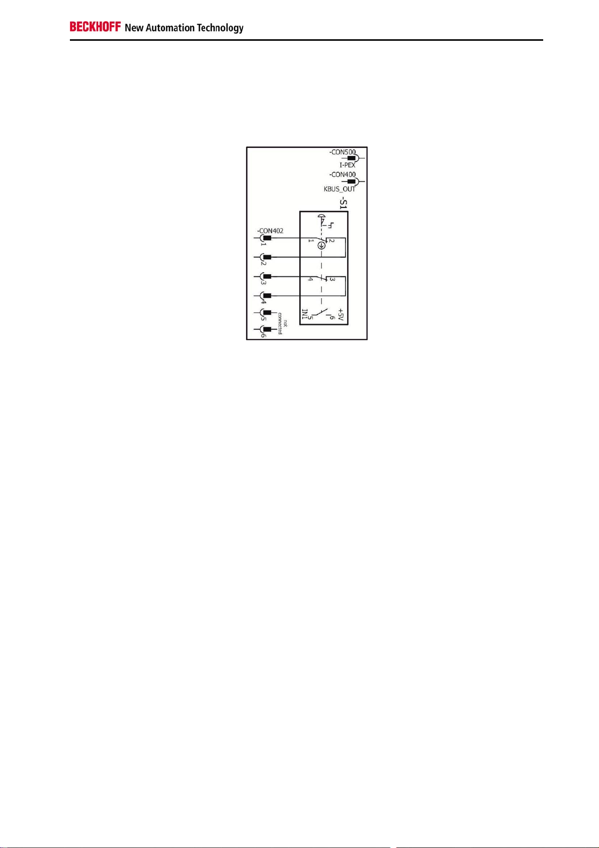
7.4 Circuit diagrams
This section shows the circuit diagrams for the PCBs used in the C9900-G0xx push-button extensions.
Additional information can be found the PCBs above (section 2.4.1).
7.4.1 Circuit diagram for emergency off PCB
C9900-G0xx 25
Page 28

Appendix
7.4.2 Circuit diagram for three-button PCB
26 C9900-G0xx
Page 29

Appendix
7.4.3 Circuit diagram for four-button PCB
C9900-G0xx 27
Page 30
Appendix
Approvals for USA and Canada
7.5 FCC certifications for the United States of America
FCC: Federal Communications Commission Radio Frequency Interference Statement
This device was tested and complies with the limits for a digital device of class A, according part 15 of the
FCC regulations. These limits are designed to provide adequate protection against adverse interference,
if the device is used in a commercial environment. This device generates, uses and may emit radio
frequency energy and may cause adverse interference with radio communications, if it is not installed and
used in accordance with the operating instructions. If this device is used in a residential area it is likely to
cause adverse interference, in which case the user must take appropriate countermeasures in order to
eliminate the interference at his own expense.
Technical modifications
Technical modifications of the device may void the FCC certification.
Note
7.6 FCC certifications for Canada
FCC: Canadian Notice
This device does not exceed the class A limits for radiation, as specified by the Radio Interference
Regulations of the Canadian Department of Communications.
28 C9900-G0xx
 Loading...