

Page 1
Installation and Operating instructions for
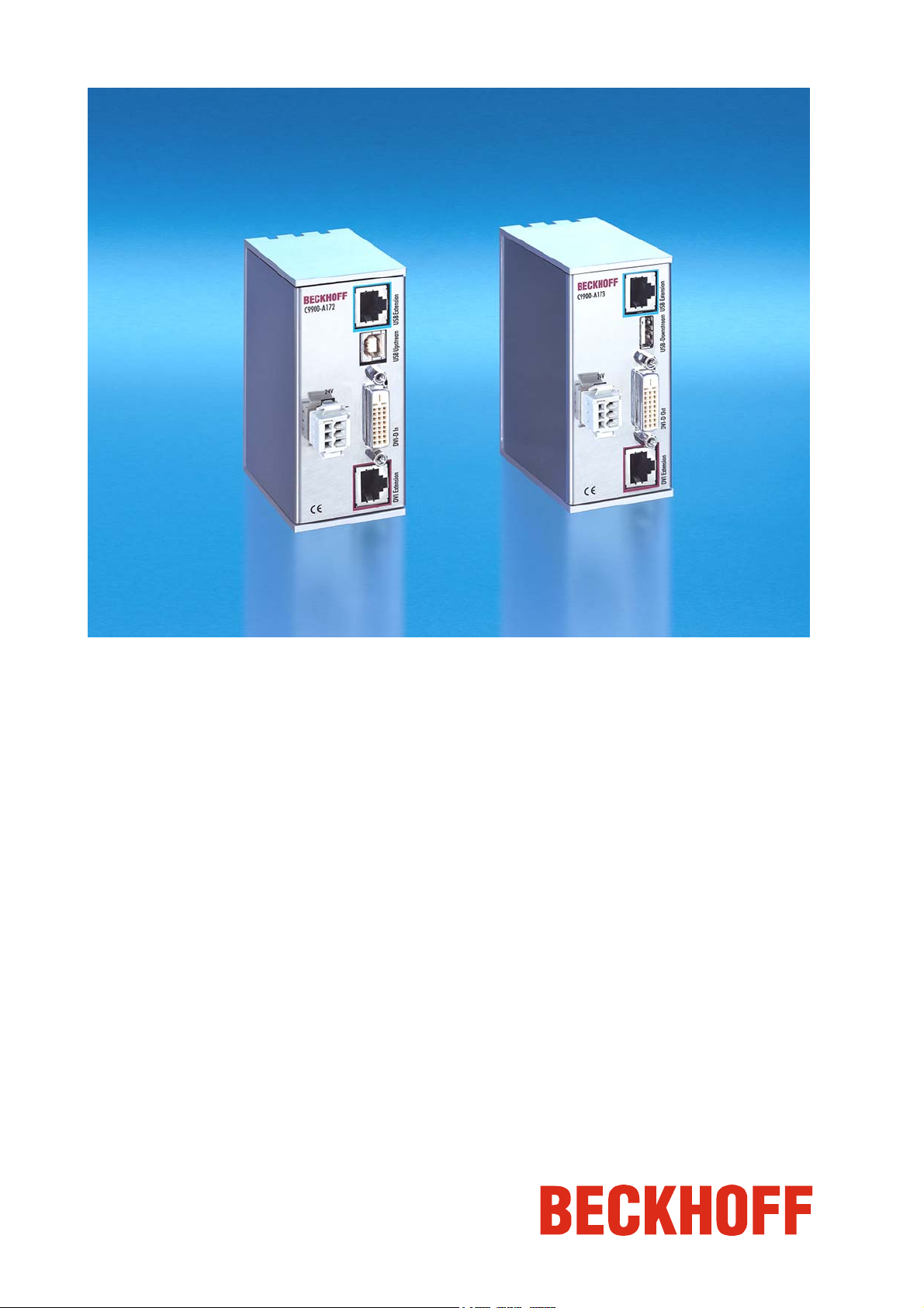
DVI/USB extension
C9900-A172/ -A173/ -A174
for CP68xx and CP78xx Control Panels
Version: 1.2
Date: 2007-08-15
Page 2

Table of contents
Table of contents
1.
General Notes 2
Notes on the documentation 2
Liability conditions 2
Description of safety symbols 2
Basic safety measures 3
Operator's obligation to exercise diligence 4
Operator requirements 4
2.
Product Description 5
Appropriate Use 5
Transmitter modules connections 5
Pin assignment 5
Connector description 6
Transmitter plug-in card connections 7
Pin assignment 7
Connector description 8
Receiver module connections 9
Pin assignment 9
Connector description 10
3.
Installation Instructions 11
Transport and Unpacking 11
Transport 11
Unpacking 11
Assembly 12
Assembly dimensions 12
Mounting of the modules 13
Installation of the transmitter card 13
Connecting modules/plug-in card 14
Cable lengths 14
Cable sets between PC and DVI/USB transmitter 14
Cable sets between transmitter and receiver 14
Cable sets between receiver and Control Panel 15
Connecting cables 15
4.
Operation Instructions 16
Functional description 16
Servicing and maintenance 16
Cleaning of the DVI/USB extension modules 16
Servicing 16
Emergency procedures 16
Shutting down 16
Disposal 16
5.
Troubleshooting 17
Fault correction 17
Service and Support 18
Beckhoff's branch offices and representatives 18
Beckhoff headquarters 18
Beckhoff Support 18
Beckhoff Service 18
6.
Appendix 19
Technical data 19
Approvals 19
FCC: Federal Communications Commission Radio Frequency Interference
Statement 19
FCC: Canadian Notice 19
DVI/USB extension C9900-A17x 1
Page 3
General Notes
General Notes
Notes on the documentation
This description is only intended for the use of trained specialists in control
and automation engineering who are familiar with the applicable national
standards. It is essential that the following notes and explanations are
followed when installing and commissioning these components.
Liability conditions
The responsible staff must ensure that the application or use of the
products described satisfy all the requirements for safety, including all the
relevant laws, regulations, guidelines and standards.
The documentation has been prepared with care. The products described
are, however, constantly under development. For this reason, the
documentation may not always be have been fully checked for consistency
with the performance data, standards or other characteristics described.
None of the statements in this manual represent a guarantee for as set out
in § 443 of the German Civil Code or a statement about the assumed use
according to the contract as set out in § 434 para. 1 clause 1 no. 1 of the
German Civil Code. In the event that it contains technical or editorial errors,
we retain the right to make alterations at any time and without warning. No
claims for the modification of products that have already been supplied
may be made on the basis of the data, diagrams and descriptions in this
documentation.
© This documentation is protected by copyright. Any reproduction or third
party use of this publication, whether in whole or in part, without the written
permission of Beckhoff Automation GmbH, is forbidden.
Description of safety symbols
i
Danger
Warning
Note
The following safety symbols are used in this operating manual. They are
intended to alert the reader to the associated safety instructions.
This symbol is intended to highlight risks for the life or health of personnel.
This symbol is intended to highlight risks for equipment, materials or the
environment.
This symbol indicates information that contributes to better understanding.
2 DVI/USB extension C9900-A17x
Page 4
General Notes
Basic safety measures
Only switch the PC off after
closing the software
Warning
Warning
i
Note
Before the Industrial PC is switched off, software that is running must
be properly closed.
Otherwise it is possible that data on the hard disk is lost. Please refer to
the notes in the instruction manual for the Industrial PC.
Switch off all parts of the equipment, then uncouple the fieldbus!
Switch off all system components and uncouple the Industrial PC from the
system before opening the PC case and whenever the PC is not used for
control purposes, e.g. during installation of the PCI bus transmitter card.
Pulling out the fieldbus connection plug uncouples the PC (optional).
Items of equipment that have been switched off must be secured against
being switched on again.
Uncouple the supply voltage before opening Industrial PC, Control
Panel or DVI/USB extension module cases!
Do not exchange any parts when under power!
When components are being fitted or removed, the supply voltage must be
switched off.
Assembly work can cause damage:
• If metal objects such as screws or tools fall onto operating circuit
• If internal connection cables are unplugged or plugged in during
• If plug-in cards are removed or inserted when the PC is switched
boards.
operation.
on.
DVI/USB extension C9900-A17x 3
Page 5

General Notes
Operator's obligation to exercise diligence
National regulations
depending on the machine
type
Procedure in the event of a
fault
Read the operating
instructions
The operator must ensure that
• the DVI/USB extension is used appropriately (see also Section
Product Description).
• the Industrial PC, Control Panel and DVI/USB extension are only
operated in sound, operational condition;
• the instruction manual is always available on site complete and in
legible condition;
• only adequately qualified and authorized staff operate the
components;
• the personnel is instructed regularly about relevant occupational
safety and environmental protection aspects, and is familiar with
the operating manual and in particular the safety notes contained
herein.
• no safety and warning notes are removed, and all notes remain
legible.
Depending on the type of machine and plant in which the DVI/ USBextension is being used, there will be national regulations for the control of
such machines and plant that the operator must observe. These
regulations cover, amongst other things, the intervals between inspections
of the controller.
The operator must initiate such inspections in good time.
In the event of a fault with the DVI/USB extension please refer to the list in
Section Fault correction for appropriate measures.
Operator requirements
All users of the DVI/USB extension must read this instruction manual.
4 DVI/USB extension C9900-A17x
Page 6
Product Description
Product Description
Do not use the modules in
potentially explosive
atmospheres
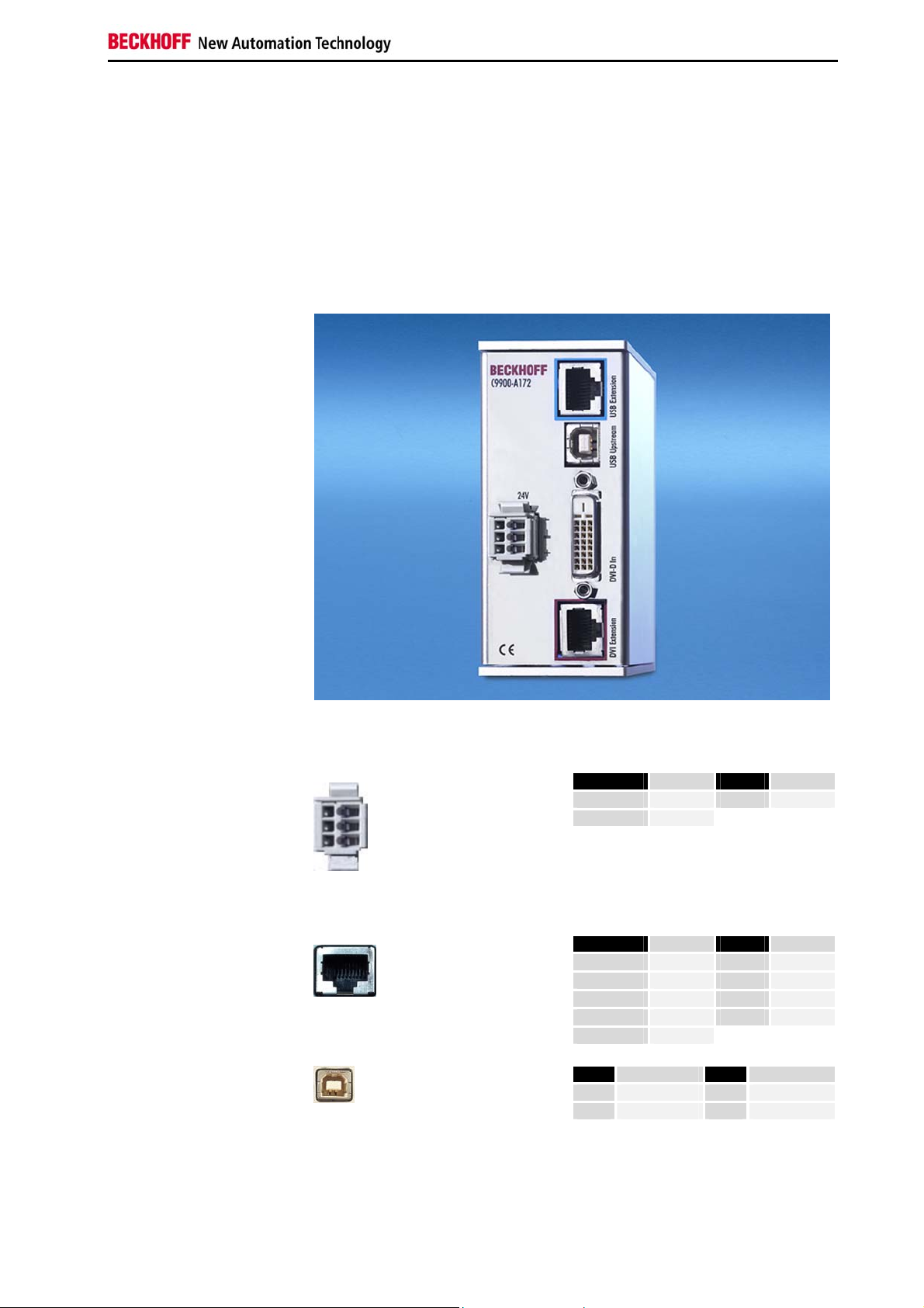
Connections of the C9900A172 transmitter module
Appropriate Use
The DVI/USB extension can be used to operate CP68xx and CP78xx
series Control Panels up to a distance of 31 meters from the Industrial PC.
The modules must not be used in potentially explosive atmospheres.
Transmitter modules connections
X 101
X 102
X 100
X 103
X 100
power supply
X 101
USB Extension
X 102
USB Upstream
Pin assignment
WAGO 734-103/ 037-000
RJ-45 connector (Ethernet 10/ 100 Mbit)
USB PCB-installation B-Type
(FCI 61729-0010B USB Receptacle B-Type)
X 104
Pin Signal Pin Signal
1
2
Pin Signal Pin Signal
Housing
1
2
3
4
- Signal Pin Signal
1
2
0 V
GND
Screen
TD +
TD RD +
n.c.
5V
D-
3
+ 24 V
5
n.c.
6
RD -
7
n.c.
8
n.c.
3
D +
4
GND
DVI/USB extension C9900-A17x 5
Page 7

Product Description
X 103
DVI-D In
DVI-D 3 X 8-pole digital
(MOLEX 74320-9000 / 74320-9004)
Pin Signal Pin Signal
1
2
3
4
5
6
7
8
9
10
11
12
Rx2Rx2GND
Rx4Rx4+
DDC CLK
DDC DAT
AV SYNC
Rx1Rx1+
GND
Rx3-
13
14
15
16
17
18
19
20
21
22
23
24
Rx3+
+ 5V DVI
GND
HPD
Rx0Rx0+
GND
Rx5Rx5+
GND
RxC+
RxC-
X 104
DVI Extension
RJ-45 connector (Ethernet 10/ 100 Mbit)
Pin Signal Pin Signal
Housing
1
2
3
4
Screen
TD +
TD RD +
n.c.
5
n.c.
6
RD -
7
n.c.
8
n.c.
Connector description
Power supply
Power supply
The cage clamp socket (X 100) is used to supply power to the DVI/USB
extension.
USB data transfer
USB Extension
The USB extension connection (X 101) is used for transferring the USB
signal from the transmitter module to the receiver module.
USB input
USB Upstream
The USB1.1 input (X 102) is used to connect the transmitter module with
the Industrial PC.
USB1.1 standard with a maximum data rate of 1.5 or 12 Mbps is
supported.
DVI input (Digital Visual Interface)
DVI-D In
The DVI connection (X 103) is used for transferring the video signal from
the Industrial PC to the transmitter module.
The purely digital part (DVI-D) is supported.
DVI data transfer
DVI Extension
The DVI extension connection (X 104) is used for transferring the DVI
signal from the transmitter module to the receiver module.
6 DVI/USB extension C9900-A17x
Page 8

Product Description
Transmitter plug-in card connections
Connections for the
C9900-A174
PCI bus transmitter plug-in
X 100
card
X 101
X 102
X 103
X 100
USB Extension
X 101
USB Upstream
X 102
DVI-D In
X 103
DVI Extension
Pin assignment
RJ-45 connector (Ethernet 10/ 100 Mbit)
USB PCB-installation B-Type
(FCI 61729-0010B USB Receptacle B-Type)
DVI-D 3 X 8-pole digital
(MOLEX 74320-9000 / 74320-9004)
RJ-45 connector (Ethernet 10/ 100 Mbit)
Pin Signal Pin Signal
Housing
1
2
3
4
Pin Signal Pin Signal
1
2
Pin Signal Pin Signal
1
2
3
4
5
6
7
8
9
10
11
12
Pin Signal Pin Signal
Housing
1
2
3
4
Screen
TD +
TD RD +
n.c.
5V
D-
Rx2Rx2GND
Rx4Rx4+
DDC CLK
DDC DAT
AV SYNC
Rx1Rx1+
GND
Rx3-
Screen
TD +
TD RD +
n.c.
3
4
13
14
15
16
17
18
19
20
21
22
23
24
5
6
7
8
D+
GND
Rx3+
+ 5V DVI
GND
HPD
Rx0Rx0+
GND
Rx5Rx5+
GND
RxC+
RxC-
5
6
7
8
n.c.
RD n.c.
n.c.
n.c.
RD n.c.
n.c.
DVI/USB extension C9900-A17x 7
Page 9

Product Description
Connector description
USB data transfer
USB Extension
The USB extension connection (X 100) is used for transferring the USB
signal from the transmitter module to the receiver module.
USB input
USB Upstream
The USB1.1 input (X 101) is used to connect the transmitter module with
the Industrial PC.
USB1.1 standard with a maximum data rate of 1.5 or 12 Mbps is
supported.
DVI input (Digital Visual Interface)
DVI-D In
The DVI connection (X 102) is used for transferring the video signal from
the Industrial PC to the transmitter module.
The purely digital part (DVI-D) is supported.
DVI data transfer
DVI Extension
The DVI extension connection (X 103) is used for transferring the DVI
signal from the transmitter module to the receiver module.
8 DVI/USB extension C9900-A17x
Page 10

Product Description
Receiver module connections
Connections of the receiver
module
C9900-A173
X 101
X 102
X 100
power supply
X 101
USB Extension
X 102
USB Downstream
X 103
DVI-D Out
X 100
Pin assignment
WAGO 734-103/ 037-000
RJ-45 connector (Ethernet 10/ 100 Mbit)
USB PCB-installation A-Type
(FCI 72309-0010B USB Receptacle A-Type)
DVI-D 3 X 8-pole digital
(MOLEX 74320-9000 / 74320-9004)
X 103
X 104
Pin Signal Pin Signal
1
2
Pin Signal Pin Signal
Housing
1
2
3
4
Pin Signal Pin Signal
1
2
Pin Signal Pin Signal
1
2
3
4
5
6
7
8
9
10
11
12
0 V
GND
Screen
TD +
TD RD +
n.c.
5V
D-
Rx2Rx2GND
Rx4Rx4+
DDC CLK
DDC DAT
AV SYNC
Rx1Rx1+
GND
Rx3-
3
4
13
14
15
16
17
18
19
20
21
22
23
24
3
5
6
7
8
D+
GND
Rx3+
+ 5V DVI
GND
HPD
Rx0Rx0+
GND
Rx5Rx5+
GND
RxC+
RxC-
+ 24 V
n.c.
RD n.c.
n.c.
DVI/USB extension C9900-A17x 9
Page 11

Product Description
X 104
DVI Extension
RJ-45 connector (Ethernet 10/ 100 Mbit)
Connector description
Power supply
Power supply
USB data transfer
USB Extension
USB output
USB Downstream
DVI output (Digital Visual Interface)
The power supply for the Control Panel is established via the Cage clamp
socket (X 100).
The USB extension connection (X 101) is used for transferring the USB
signal from the transmitter module to the receiver module.
The USB1.1 input (X 102) is used to connect the receiver module with the
Control Panel.
USB1.1 standard with a maximum data rate of 1.5 or 12 Mbps is
supported.
Pin Signal Pin Signal
Housing
1
2
3
4
Screen
TD +
TD RD +
n.c.
5
n.c.
6
RD -
7
n.c.
8
n.c.
DVI-D Out
The DVI connection (X 103) is used for transferring the video signal from
the receiver module to the Control Panel.
The purely digital part (DVI-D) is supported.
DVI data transfer
DVI Extension
The DVI extension connection (X 104) is used for transferring the DVI
signal from the transmitter module to the receiver module.
10 DVI/USB extension C9900-A17x
Page 12

Installation Instructions
Installation Instructions
Warning
Please also refer to chapter General Notes.
Transport and Unpacking
The specified storage conditions must be observed (see chapter Technical
data).
Transport
Despite the robust design of the unit, the components are sensitive to
strong vibrations and impacts. Therefore please protect the modules or the
transmitter card from strong mechanical influences during transport.
Therefore, please use the original packaging.
Danger of damage to the unit!
When transporting the devices in cold weather or during strong
temperature fluctuations, condensation on or in the devices should be
avoided.
Adjust the devices slowly to room temperature before switching them on. If
condensation has formed, wait for approx. 12 hours before switching the
devices on.
Unpacking
Unpack the devices as follows:
1. Remove packaging.
2. Do not discard the original packaging. Keep it for future relocation.
3. Check the delivery for completeness by comparing it with your order.
4. Please keep the associated paperwork. It contains important
information for handling the unit.
5. Check the contents for visible shipping damage.
6. If you notice any shipping damage or inconsistencies between the
contents and your order, you should notify Beckhoff Service.
DVI/USB extension C9900-A17x 11
Page 13

Installation Instructions
Assembly
Transmitter module
C9900-A172
Assembly dimensions
All dimensional notations in mm.
Receiver module
C9900-A173
12 DVI/USB extension C9900-A17x
Page 14

Installation Instructions
Mounting of the modules
The transmitter and receiver modules can be mounted on a top hat rail.
Mounting of the transmitter
and receiver modules
Installation of the transmitter card
The mains plug of the Industrial PCs must be disconnected!
Warning
Mounting of the PCI bus
transmitter card
Open the Industrial PC according to the instruction manual.
The PCI bus transmitter plug-in card is installed in the Industrial PC.
Remove the cover of a free slot and insert the transmitter card.
Secure the transmitter plug-in card with the Phillips screw and
close the Industrial PC.
DVI/USB extension C9900-A17x 13
Page 15

Installation Instructions
Connecting modules/plug-in card
The connections must never be established or disconnected in potentially
Danger
Warning
explosive atmospheres! Risk of explosion!
The mains plug of the Industrial PCs must be disconnected!
Please read the documentation for the external devices prior to connecting
them.
During thunderstorms, plug connector must neither be inserted nor
removed.
When disconnecting a plug connector, always handle it at the plug. Do not
pull the cable!
Cable lengths
Cable sets between PC and DVI/USB transmitter
Order number
C9900-K260
C9900-K261
C9900-K262
Denomination
Connection set for C9900-A174 consisting of:
DVI cable 0.40 m, USB cable 0.40 m
Connection set for C9900-A172 consisting of:
DVI cable 1,00 m, USB cable 1,00 m
Connection set for C9900-A172 consisting of:
DVI cable 3,00 m, USB cable 3,00 m
Cable sets between transmitter and receiver
Order number
C9900-K411
C9900-K412
C9900-K413
C9900-K414
C9900-K415
Denomination
Patch cable set RJ45 CAT7 5 m
Patch cable set RJ45 CAT7 10 m
Patch cable set RJ45 CAT7 15 m
Patch cable set RJ45 CAT7 20 m
Patch cable set RJ45 CAT7 25 m
14 DVI/USB extension C9900-A17x
Page 16

Installation Instructions
CAT 7 cable with RJ 45
connector
Cable sets between receiver and Control Panel
Order number
C9900-K510
Denomination
Connection set for CP68xx consisting of:
DVI cable 3 m, USB cable 3 m and power supply
connector
C9900-K514
Connection set for CP78xx consisting of:
DVI cable 3 m, USB cable 3 m and power supply
connector; IP-65 connector at the Control Panel
Connecting cables
The connections are located at the front of the modules and are
documented in Section Product Description.
Please refer to the respective instruction manuals regarding the
configuration of the connections at the Industrial PC (if a PCI bus
transmitter card is used) and at the Control Panel.
When connecting cables, please adhere to the following order:
• Switch off the Industrial PC
• Disconnect the Industrial PC from the power supply
• Connect all cables at the modules, the Control Panel, and the
devices to be connected
• Ensure that all screw connections (if present) between plug
connectors and sockets are tight!
• Connect the DVI/USB extension modules with the 24 V power
supply. The PCI bus transmitter card is supplied via the Industrial
PC.
• Reconnect all devices to the power supply.
Two standard CAT 7 cables with RJ 45 connector are used for the
connections between transmitter module and receiver module, and
transmitter card and receiver module.
DVI/USB extension C9900-A17x 15
Page 17

Operation Instructions
Operation Instructions
Functional description
Switching on
First switch the Industrial
PC off
The transmitter and receiver modules have no dedicated mains switch. The
modules are ready for operation as soon as the central 24 V power supply
has been switched on.
The transmitter plug-in card is switched on via the Industrial PC.
Servicing and maintenance
Please also refer to chapter General Notes.
Cleaning of the DVI/USB extension modules
Switch off the Industrial PC and all connected devices. Disconnect the
modules from the 24 V power supply.
The module cases can be cleaned with a damp, soft cloth. Do not use any
aggressive cleaning materials, thinners, scouring material or hard objects
that could cause scratches.
Servicing
The transmitter and receiver modules and the transmitter plug-in card are
maintenance-free.
Emergency procedures
In the event of a fire use powder or nitrogen as extinguishing medium for
the modules.
Shutting down
Disposal
Modules should be
dismantled
Observe national
electronics scrap
regulations
For disposal the modules should be fully dismantled. The housing can be
sent for metal recycling.
Electronic parts must be disposed of in accordance with national
electronics scrap regulations.
16 DVI/USB extension C9900-A17x
Page 18

Troubleshooting
Troubleshooting
Please also refer to chapter General Notes.
Fault correction
Fault Cause Procedures
The control panel shows no
function when the Industrial PC has
been started
Cable not connected or connected
incorrectly
No power supply
Fault in the Industrial PC or Control
Panel
1. Correctly connect cable
2. Call Beckhoff Service
Check power supply cable
Please refer to the
troubleshooting sections in
the respective operating
instructions
DVI/USB extension C9900-A17x 17
Page 19

Troubleshooting
Service and Support
Quote the project number
Beckhoff and their partners around the world offer comprehensive service
and support, making available fast and competent assistance with all
questions related to Beckhoff products and system solutions.
Beckhoff's branch offices and representatives
Please contact your Beckhoff branch office or representative for local
support and service on Beckhoff products!
The addresses of Beckhoff's branch offices and representatives round the
world can be found on her internet pages:
http://www.beckhoff.com
You will also find further documentation
for Beckhoff components there.
Beckhoff headquarters
Beckhoff Automation GmbH
Eiserstraße 5
D-33415 Verl
Germany
Phone:
Fax: +49(0)5246/963-198
e-mail: info@beckhoff.com
+49(0)5246/963-0
Beckhoff Support
Support offers you comprehensive technical assistance, helping you no
only with the application of individual Beckhoff products, but also with
other, wide-ranging services:
• world-wide support
• design, programming and commissioning of complex automation
systems
• and extensive training program for Beckhoff system components
Hotline:
Fax: +49(0)5246/963-9157
e-mail: support@beckhoff.com
+49(0)5246/963-157
Beckhoff Service
The Beckhoff Service Center supports you in all matters of after-sales
service:
• on-site service
• repair service
• spare parts service
• hotline service
Hotline:
Fax: +49(0)5246/963-479
e-mail: service@beckhoff.com
If servicing is required, please quote the project number of your Industrial
PC.
+49(0)5246/963-460
18 DVI/USB extension C9900-A17x
Page 20

Appendix
Appendix
Technical data
Dimensions
Operation in areas that are
subject to explosion hazard
The following conditions must be observed during operation:
Environmental conditions
Shock resistance Sinusoidal vibration:
Protection class
Power supply
EMC compatibility
Transport and storage
Dimensions (W x H x D): see section Assembly dimensions
The modules must not be used in potentially explosive atmospheres.
Ambient temperature: 0 to 55°C
Atmospheric humidity: Maximum 95%, non-condensing
(EN 60068-2-6)
58 to 500 Hz: 0.5 G (~ 5 m/ s
Impact:
(EN 60068-2-27/ 29)
Modules: IP20
Supply voltage: The modules have an integrated 24 V
power supply unit.
The PCI bus transmitter plug-in card is
supplied via the Industrial PC.
Power consumption: C9900-A172: 0,4 W
C9900-A173: 2,0 W
Resistance to interference: conforms to EN 61000-6-2
Emission of interference: conforms to EN 61000-6-4
The same values for atmospheric humidity and shock resistance are to be
observed during transport and storage as in operation. The shock
resistance of the modules/transmitter card during transport can be
improved through suitable packaging. The ambient temperature during
storage and transport must be between -20°C and +65°C.
10 to 58 Hz: 0.035 mm
5 G (~ 50 m/ s²), duration: 30 ms
2
)
Approvals
FCC Approval for USA
FCC Approval for Canada
FCC: Federal Communications Commission Radio Frequency Interference Statement
This equipment has been tested and found to comply with the limits for a
Class A digital device, pursuant to Part 15 of the FCC Rules. These limits
are designed to provide reasonable protection against harmful interference
when the equipment is operated in a commercial environment. This
equipment generates, uses, and can radiate radio frequency energy and, if
not installed and used in accordance with the instruction manual, may
cause harmful interference to radio communications. Operation of this
equipment in a residential area is likely to cause harmful interference in
which case the user will be required to correct the interference at his own
expense.
FCC: Canadian Notice
This equipment does not exceed the Class A limits for radiated emissions
as described in the Radio Interference Regulations of the Canadian
Department of Communications.
DVI/USB extension C9900-A17x 19
 Loading...