

Page 1
Installation and Operating instructions for
Control Cabinet PCs C63xx -0030
-0040
Version: 1.3
Date: 2011-02-21
Page 2

Page 3

Table of contents
Table of contents
1.
General instructions 3
Notes on the Documentation 3
Liability Conditions 3
Description of safety symbols 3
Basic safety measures 4
Operator's obligation to exercise diligence 5
Operator requirements 5
2.
Product Description 6
Appropriate Use 6
Structure C6320, C6330 6
Structure C6325, C6335 8
Structure C6340, C6350 10
Interfaces 12
USB interfaces 12
Network connection 12
DVI interface 12
USB interface 12
Serial interface 12
Additional plug-in cards (optional) 12
3.
Installation Instructions 13
Transport and Unpacking 13
Transport 13
Unpacking 13
Installation of the PC in the control cabinet 14
Power Supply Connection 15
Pin assignment of the connector 15
Fitting the cable 16
Material for assembling the connectors 16
Assembling the connectors 16
Connecting Power Supply 17
Cable Cross Sections 17
PC_ON, Power-Status, UPS output 17
Wiring diagram 18
Connecting devices 19
Connecting cables 19
Check voltage rating and connect 19
4.
Operating Instructions 20
Switching the Industrial PC on and off 20
First switching on and driver installation 20
Maintenance 21
Cleaning the Industrial PC 21
Replacing the battery on the motherboard 21
Servicing 21
Shutting down 21
Disposal 21
5.
UPS Software Components (optional) 22
Installation on the PC 22
Help files 22
1 C63xx
Page 4

Table of contents
6.
Troubleshooting 23
Fault correction 23
Beckhoff Support & Service 24
Beckhoff branches and partner companies 24
Beckhoff Headquarters 24
Beckhoff Support 24
Beckhoff Service 24
7.
Assembly dimensions 25
8.
Appendix 31
Technical data 31
Approvals 32
FCC: Federal Communications Commission Radio Frequency Interference
Statement 32
FCC: Canadian Notice 32
2 C63xx
Page 5
General instructions
General instructions
Notes on the Documentation
This description is only intended for the use of trained specialists in control
and automation engineering who are familiar with the applicable national
standards. It is essential that the following notes and explanations are
followed when installing and commissioning these components.
Liability Conditions
The responsible staff must ensure that the application or use of the
products described satisfy all the requirements for safety, including all the
relevant laws, regulations, guidelines and standards.
The documentation has been prepared with care. The products described
are, however, constantly under development. For that reason the
documentation is not in every case checked for consistency with
performance data, standards or other characteristics. None of the
statements of this manual represents a guarantee (Garantie) in the
meaning of § 443 BGB of the German Civil Code or a statement about the
contractually expected fitness for a particular purpose in the meaning of
§ 434 par. 1 sentence 1 BGB. In the event that it contains technical or
editorial errors, we retain the right to make alterations at any time and
without warning. No claims for the modification of products that have
already been supplied may be made on the basis of the data, diagrams
and descriptions in this documentation.
© This documentation is copyrighted. Any reproduction or third party use of
this publication, whether in whole or in part, without the written permission
of Beckhoff Automation GmbH, is forbidden.
Description of safety symbols
i
Danger
Warning
Note
The following safety symbols are used in this operating manual. They are
intended to alert the reader to the associated safety instructions.
This symbol is intended to highlight risks for the life or health of personnel.
This symbol is intended to highlight risks for equipment, materials or the
environment.
This symbol indicates information that contributes to better understanding.
C63xx 3
Page 6

General instructions
Basic safety measures
Only switch the PC off after
closing the software
Warning
Danger
Before the Industrial PC is switched off, software that is running must
be properly closed.
Otherwise it is possible that data on the hard disk is lost. Please read the
section on Switching the Industrial PC on and off.
Switch off all parts of the equipment, then uncouple the fieldbus!
Before opening the housing of the PC, and whenever the PC is being used
for purposes other than plant control, such as during functional tests
following repair, all parts of the equipment must first be switched off, after
which the Industrial PC can be uncoupled from the plant.
Pulling out the fieldbus connection plug uncouples the PC (optional).
Items of equipment that have been switched off must be secured against
being switched on again.
The Industrial PC’s power supply unit must be supplied with 24 V
DC
.
Do not exchange any parts when under power!
When components are being fitted or removed, the supply voltage must be
switched off.
Fitting work on the Industrial PC can result in damage:
• If metal objects such as screws or tools fall onto operating circuit
boards.
• If connecting cables internal to the PC are removed or inserted
during operation.
• If plug-in cards are removed or inserted when the PC is switched
on.
4 C63xx
Page 7

General instructions
Operator's obligation to exercise diligence
National regulations
depending on the machine
type
Warning
Procedure in the event of a
fault
The operator must ensure that
• the Industrial PC is only used for its intended use (see also
Product Description chapter).
• the Industrial PC is in a sound condition and in working order
during operation.
• the operation manual is in good condition and complete, and
always available for reference at the location of the Industrial PC.
• the Industrial PC is operated, maintained and repaired only by
sufficiently qualified and authorized personnel.
• the personnel is instructed regularly about relevant occupational
safety and environmental protection aspects, and is familiar with
the operating manual and in particular the safety notes contained
herein.
• none of the safety and warning notes attached to the Industrial PC
are removed, and that all notes remain legible.
Depending on the type of machine and plant in which the Industrial PC is
being used, there will be national regulations for the control of such
machines and plant that the operator must observe. These regulations
cover, amongst other things, the intervals between inspections of the
controller.
The operator must initiate such inspections in good time.
Only trained persons may open the Industrial PC housing!
The operator is responsible for ensuring that only trained electrical staff
opens the housing of the Industrial PC.
In the event of a fault in the Industrial PC, appropriate measures can be
determined with the aid of the list in the Fault correction section.
Operator requirements
Read the operating
instructions
Software knowledge
Every user of the Industrial PC must have read these operating
instructions.
Every user must be familiar with any of the functions of the software
installed on the PC that he can reach.
C63xx 5
Page 8
Product Description
Product Description
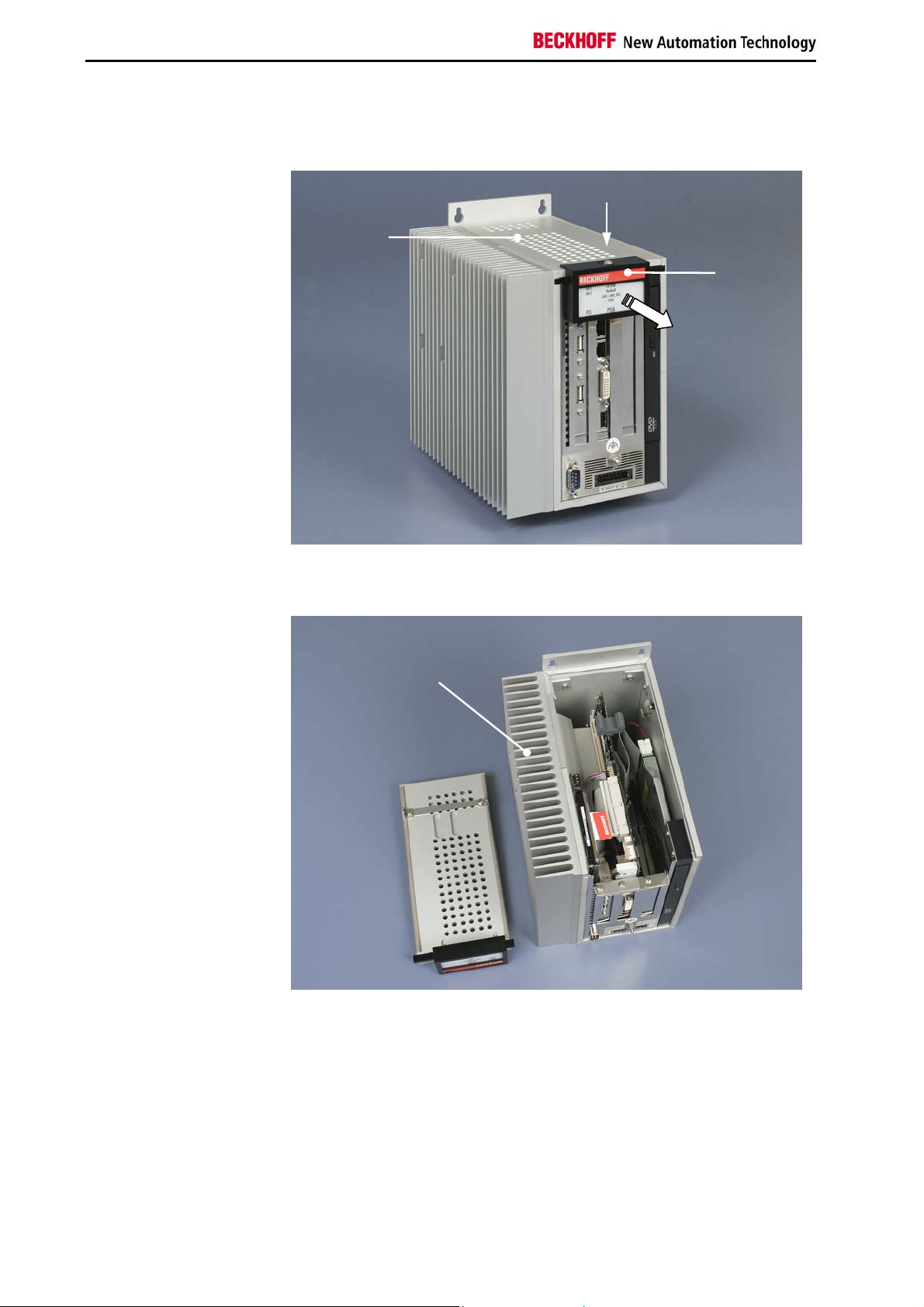
Example: Front view of
Industrial PC C6330
in basic configuration
Appropriate Use
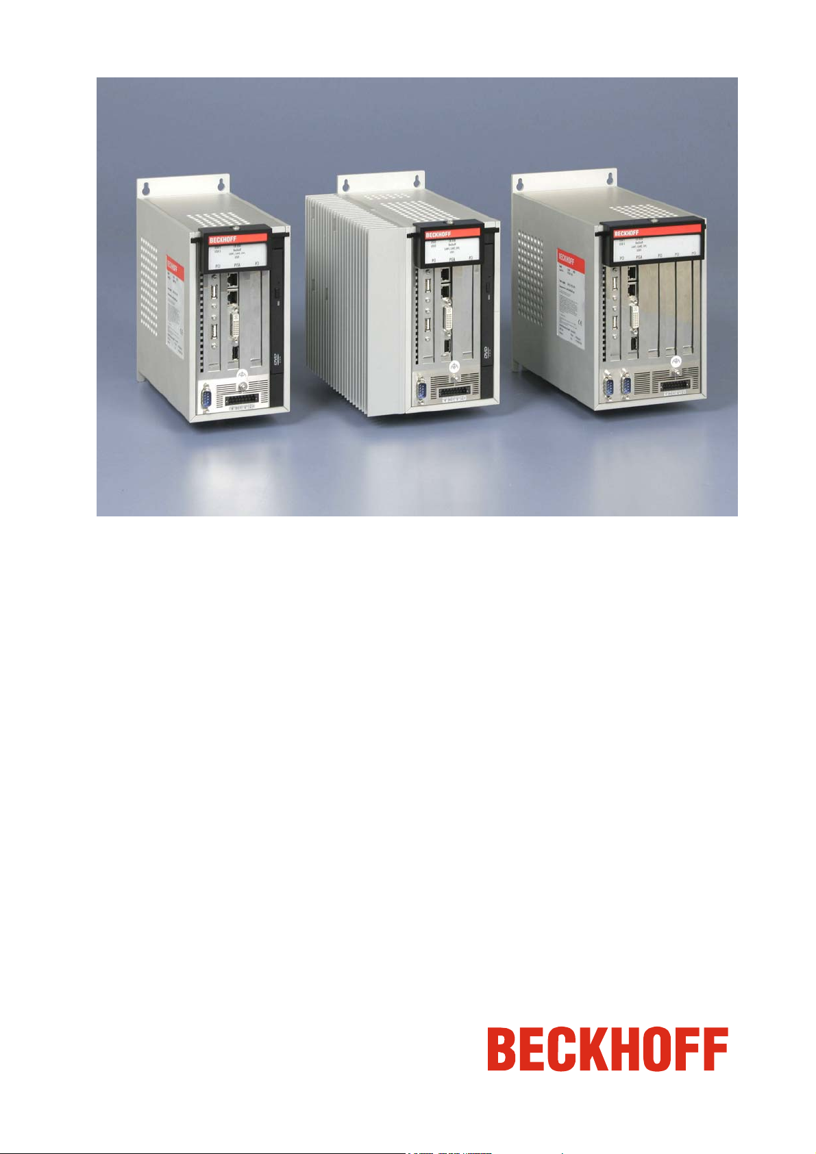
The C63xx series Industrial PCs in connection with a DVI / USB-ControlPanel CP68xx or CP78xx are designed for mounting in control cabinets for
machine and plant engineering applications.
The PCs of the series C63xx-0030 and C63xx-0040 differ in the
configuration of the processor.
Structure C6320, C6330
Configuration with 3 PCI-Slots
1
3
1
2
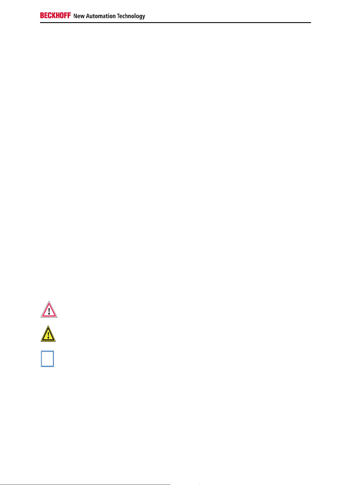
Opening the housing
Top view of the open
housing
To open the PC housing, release the screw (1) by one turn using a
screwdriver. The plastic cap (2) can be then be pulled forward, thereby
releasing the lid (3).
1
The aluminium lid can now be lifted off. Avoid damaging the electrical
contacts for the power supply line of the fan (1)!
6 C63xx
Page 9
Product Description
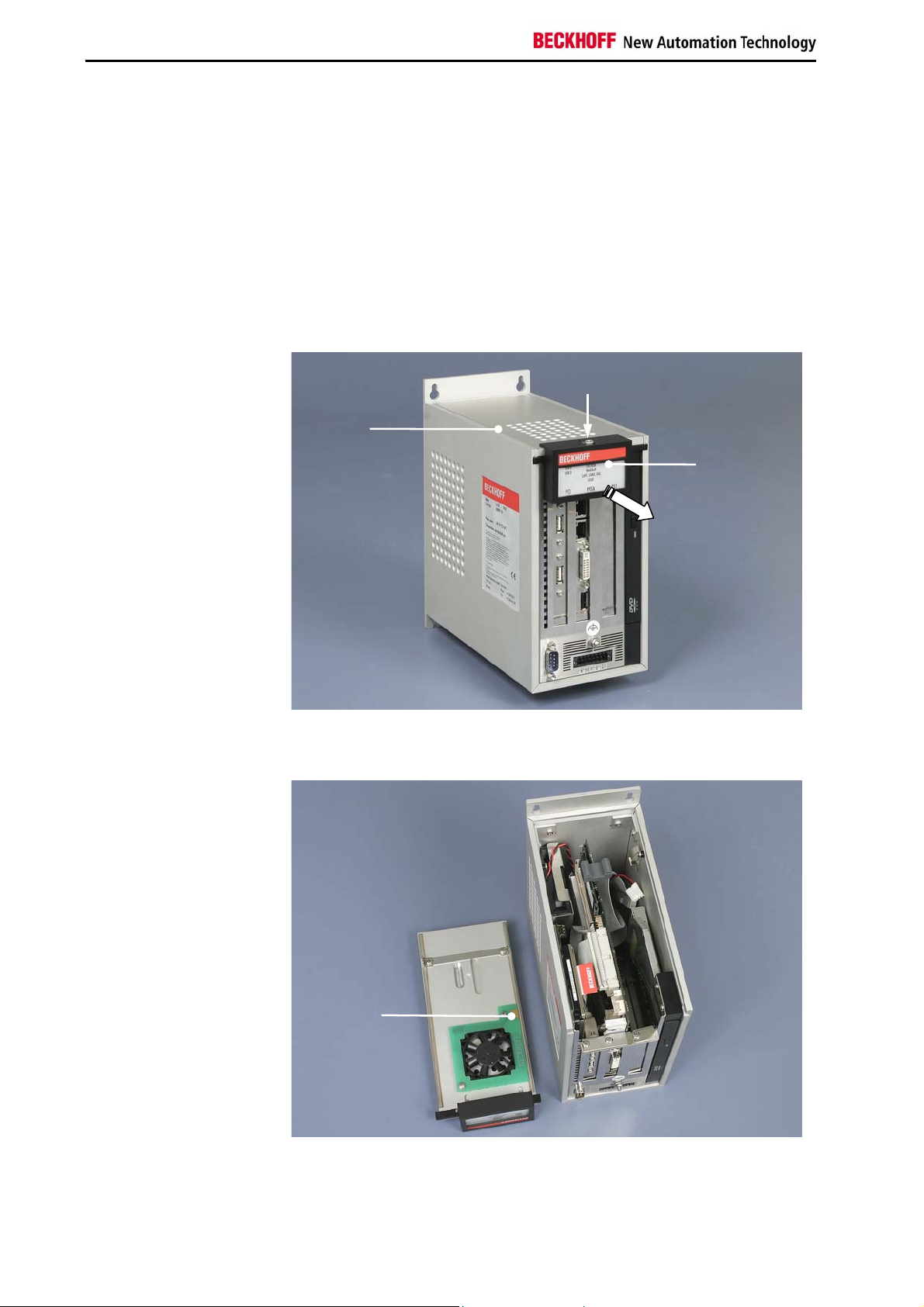
View of the open PC
C6330
2
3
4
1
The computer chassis can now be removed from the housing.
The power supply is located in the lower part of the chassis (1), the
2,5” hard disk is located in the upper part (2).
The slot motherboard (3) is located in the second slot of the housing.
The Slim Line CD-ROM drive (4) is visible right on the picture
(only C6330).
C63xx 7
Page 10
Product Description
Structure C6325, C6335
Example:
Front view of the C6335
in basic configuration
Opening the housing
Top view of the open
housing
Configuration without fan
1
3
2
To open the PC housing, release the screw (1) by one turn using a
screwdriver. The plastic cap (2) can be then be pulled forward, thereby
releasing the lid (3).
1
The aluminium lid can now be lifted off.
The heatsink (1) enables the fanless operation up to an ambient air
temperature of 45
o
C.
8 C63xx
Page 11
Product Description
View of the open PC
C6335
2
3
4
1
The computer chassis can now be removed from the housing.
The power supply is located in the lower part of the chassis (1), the
2,5” hard disk is located in the upper part (2).
The slot motherboard (3) is located in the second slot of the housing.
The Slim Line CD-ROM drive (4) is visible right on the picture (only C6335)
C63xx 9
Page 12

Product Description
Structure C6340, C6350
Example: Front view of
Industrial PC C6340
in basic configuration
Opening the housing
Top view of the open
housing
Configuration with 5 PCI-Slots
1
3
2
To open the PC housing, release the screw (1) by one turn using a
screwdriver. The plastic cap (2) can be then be pulled forward, thereby
releasing the lid (3).
1
The aluminium lid can now be lifted off. Avoid damaging the electrical
contacts for the power supply line of the fan (1)!
10 C63xx
Page 13

Product Description
View of the open PC
C6340
2
3
1
The computer chassis can now be removed from the housing.
The power supply is located in the lower part of the chassis (1), the
2,5” hard disk is located in the upper part (2).
The slot motherboard (3) is located in the second slot of the housing.
C63xx 11
Page 14

Product Description
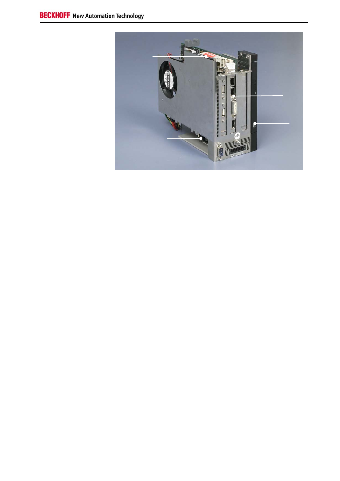
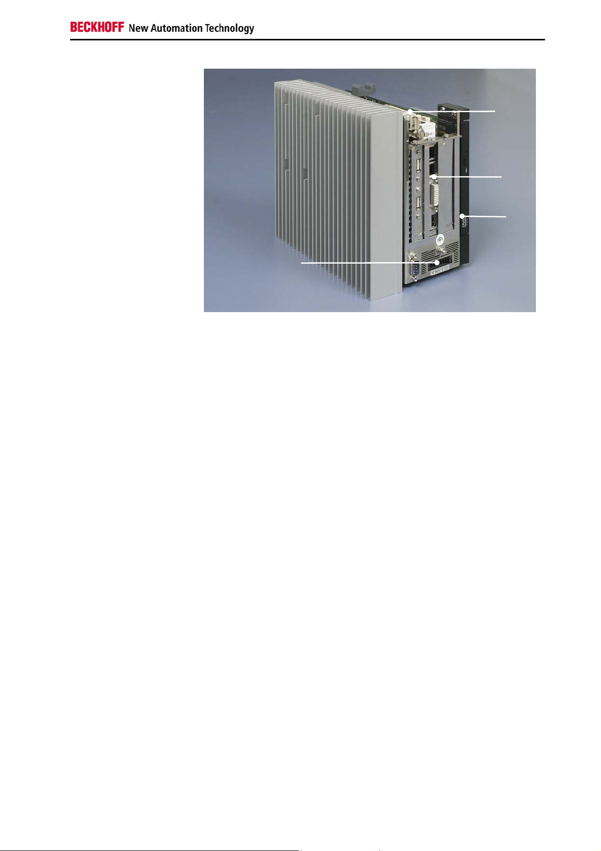
Interfaces to the
C63xx Industrial PCs
Interfaces
3
1
4
5
2
6
USB1 – USB2
Network
DVI-I
USB3
RS 232
COM2
USB interfaces
The two USB interfaces (1) and (2) are used for connecting the Control
Panel CP68xx or CP78xx. USB2.0 standard is supported.
Alternatively, peripheral devices with USB port may be connected.
Network connection
The PC is connected with the local network via the 10/100 Base-T RJ-45
connectors (3) and (4) of the On-Board Ethernet adapter.
DVI interface
The DVI interface (5) is used for connecting the Control Panel CP68xx or
CP78xx. Alternatively, a monitor with DVI input or VGA input can be
connected.
For connecting a monitor with VGA input the adapter C9900-Z411 or
C9900-Z413 is required additionally:
• C9900-Z411: Adapter plug DVI-I to VGA
• C9900-Z413: Adapter cable DVI-I to DVI and VGA, 15cm
USB interface
An additional USB-interface (6) is used for connecting peripheral devices
with USB port. USB2.0 standard is supported.
Serial interface
The basic version of the C63xx Industrial PC has one serial
interface COM2, using the type RS232, which is brought to a
9 pin SUB-D plug connector. The interface is located next to
the power supply connector.
The COM3 interface is internally connected to the power
supply unit.
Additional plug-in cards (optional)
Type plate
12 C63xx
A type plate is located at the plastic cap of the PC housing, providing
information about the Industrial PC equipment as delivered.
Page 15

Installation Instructions
Installation Instructions
Warning
Please also refer to chapter General instructions.
Transport and Unpacking
The specified storage conditions must be observed (see chapter Technical
data).
Transport
Despite the robust design of the unit, the components are sensitive to
strong vibrations and impacts. During transport, your Industrial PC should
therefore be protected from excessive mechanical stress. Therefore,
please use the original packaging.
Danger of damage to the unit!
If the device is transported in cold weather or is exposed to extreme
variations in temperature, make sure that moisture (condensation) does not
form on or inside the device.
Prior to operation, the unit must be allowed to slowly adjust to room
temperature. Should condensation occur, a delay time of approximately 12
hours must be allowed before the unit is switched on.
Unpacking
Proceed as follows to unpack the unit:
1. Remove packaging.
2. Do not discard the original packaging. Keep it for future relocation.
3. Check the delivery for completeness by comparing it with your order.
4. Please keep the associated paperwork. It contains important
information for handling the unit.
5. Check the contents for visible shipping damage.
6. If you notice any shipping damage or inconsistencies between the
contents and your order, you should notify Beckhoff Service.
C63xx 13
Page 16
Installation Instructions
Installation of the PC in the control cabinet
Preparation of the control
cabinet
i
Note
Warning
Earthing measures
The C63xx Industrial PCs are designed for mounting in control cabinets for
machine and plant engineering applications.
The ambient conditions specified for operation must be observed (see
chapter Technical data).
Four holes for the fixing bolts have to be provided in the control cabinet
according to the dimensions of the PC (see chapter Assembly dimensions).
When the unit is installed in an enclosure, adequate space for
ventilation and for opening the PC must be provided.
Extreme environmental conditions should be avoided as far as
possible. Protect the PC from dust, moisture and heat.
The ventilation slots of the PC must not be covered.
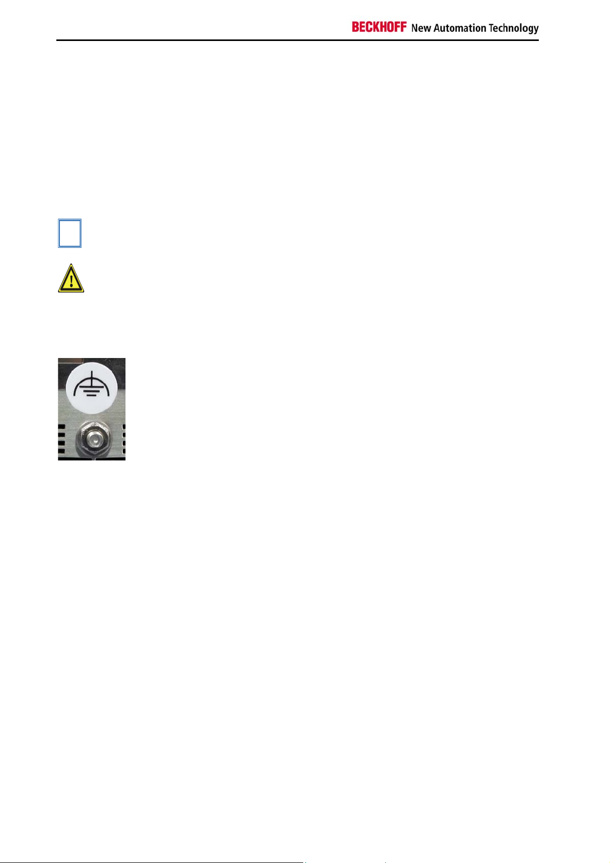
Earthing connections dissipate interference from external power supply
cables, signal cables or cables to peripheral equipment.
Establish a low-impedance connection from the earthing point on the PC
housing to the central earthing point on the control cabinet wall, in which
the computer is being installed. The earthing connection is located at the
top of the housing (see photograph on the left).
14 C63xx
Page 17
Installation Instructions
Power Supply Connection
Supplied mains power unit
i
Note
Danger
Pin assignment for
connecting the switch, the
power supply and the
battery pack (optional)
The Industrial PC is fitted with a 24 V
power supply unit .
DC
When the Industrial PC is provided with a power supply unit with integrated
UPS (order option) you can realize an uninterruptible power supply (UPS)
using the battery pack C9900-U330.
Danger of Explosion if using other battery packs!
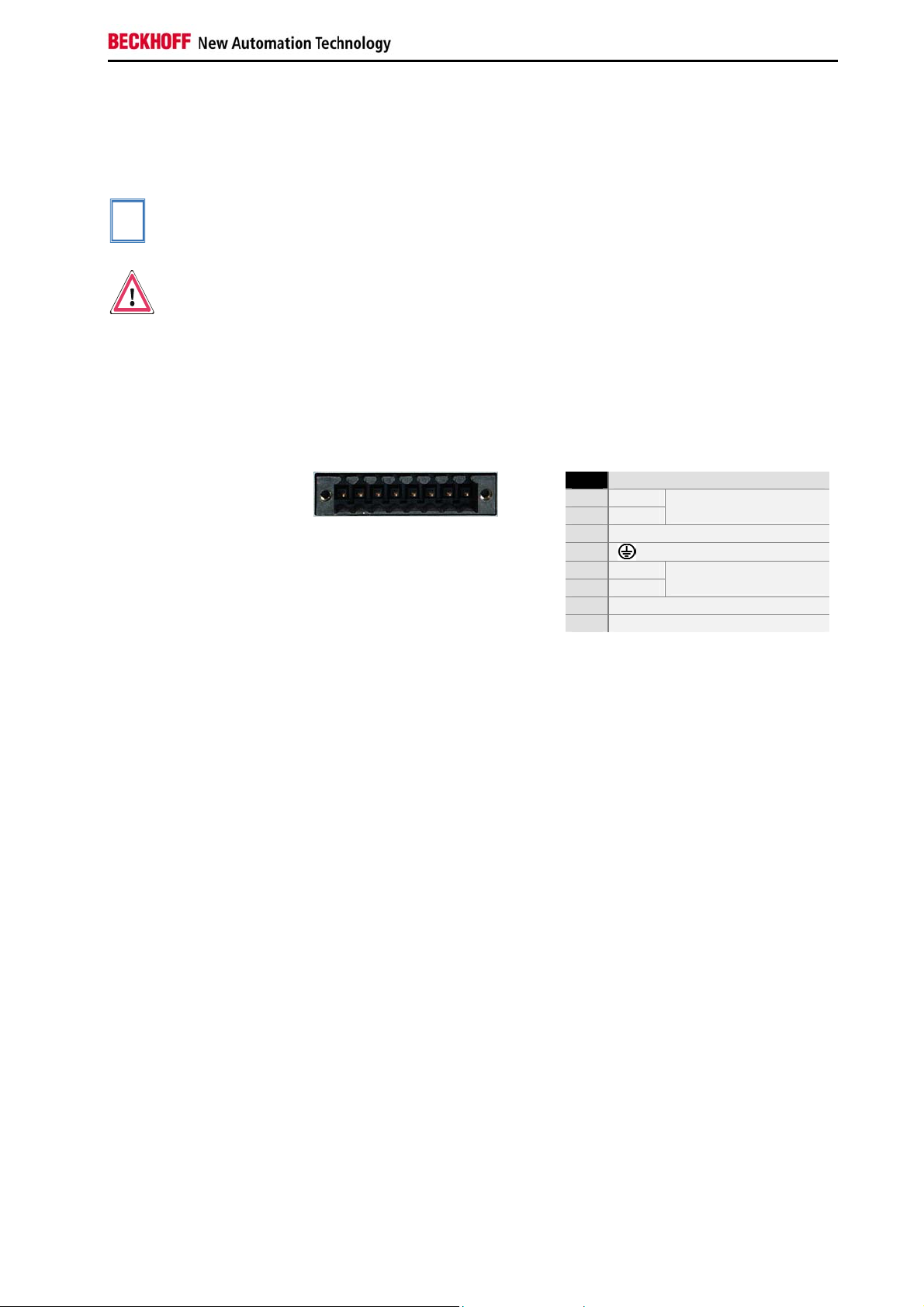
Pin assignment of the connector
The power supply and the external circuit for switching the Industrial PC on
and off are connected via the 8-pole plug connector .
Pin Function
1 2 3 4 5 6 7 8
1
-
2
+
3
UPS+ (Output)
4
5
-
6
+
7
PC_ON
8
Power-Status
Battery Pack
(with UPS only)
24 V DC
Power Supply
C63xx 15
Page 18
Installation Instructions
Fitting the cable
Wiring in accordance with
wiring diagram
Material for assembling the connectors
Conductive cross-section
Fitting the connector to the
cable
Applying the strain relief
Putting in the plug
connector
Fixing the upper part of the
strain relief housing
Fit the cables for the power supply of the Industrial PC, the connection of
the battery pack as well as the connection of the power-switch in
accordance with the wiring diagram, using the included material for
assembling the connectors.
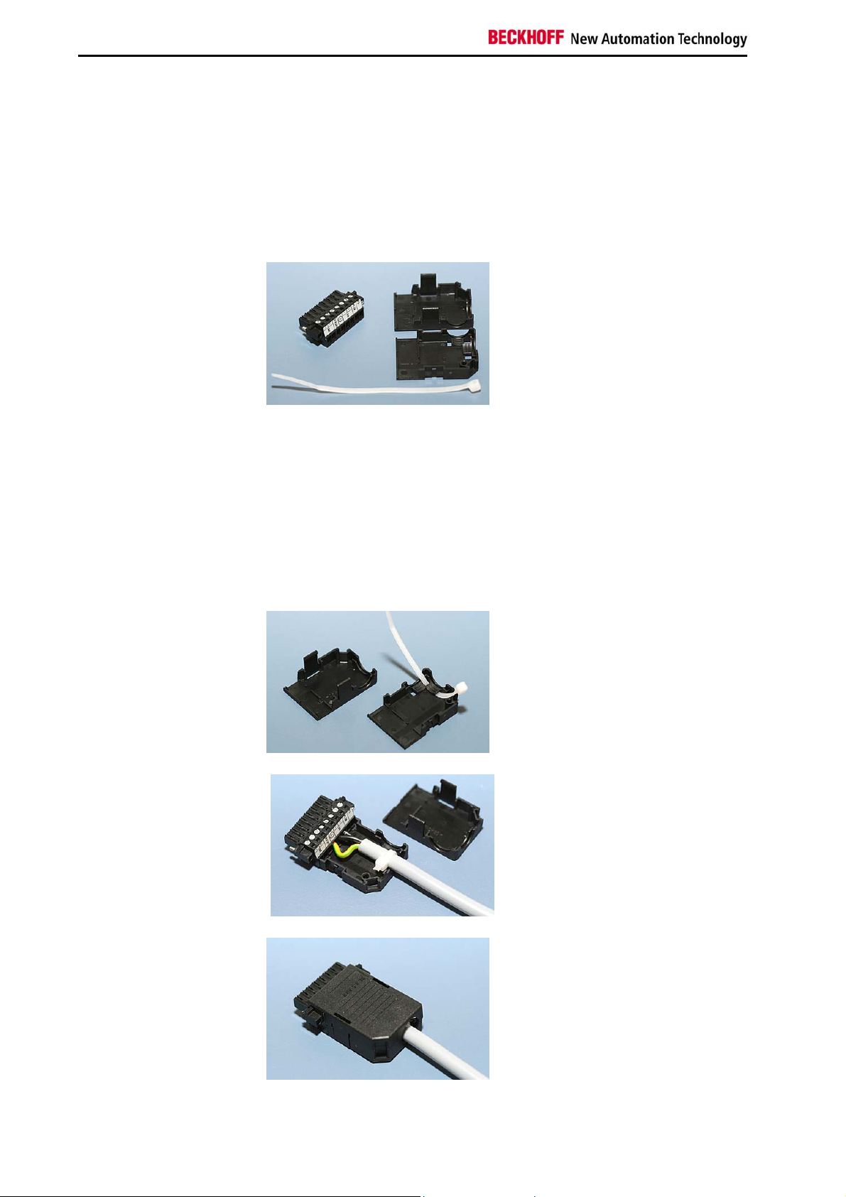
Material for assembling the connectors
Plug connector 8-pole, Strain
relief housing with lacing cord
Assembling the connectors
The connector is specified for 16 A and can lift conductive cross-sections
until 1.5 mm
So the connector is fitted to the cable:
1. Strip insulation from the cable ends (Length of stripped conductor
2. Screw together the cable ends in the 8-pole plug connector in
2
.
is 8 – 9 mm).
accordance with wiring diagram.
Thread the lacing cord into that
lower part of the strain relief
housing.
Put the plug connector into that
lower part of the strain relief
housing.
Tighten the lacing cord and pinch off
the plastic strap.
Fix the upper part of the strain relief
housing by snapping it onto the
lower part.
16 C63xx
Page 19

Installation Instructions
Connecting Power Supply
The external wiring consists of the connection of the power supply, the
battery pack (optional) and the connection of customised components for
shutting down the PC.
Cable Cross Sections
Note cable cross sections,
avoid voltage drop!
Insert Fuse The power supply must be protected with maximum 16 A.
For the connection of the power supply, wiring with a cable-cross-section
of 1,5 mm2 must be used.
With bigger distances between voltage source and PC, you take the
voltage drop as a function of the cable-cross-section as well as voltage
fluctuations of your distribution voltage into account, so that is secured that
the voltage doesn't fall under 22 V at the power supply.
PC_ON, Power-Status, UPS output
The circuit for shutting down the Industrial PC is realized using the inputsignal PC_ON and the output-signal Power-Status:
• The PC starts shutting down if 24 V exists at PC_ON, for example
using a switch.
• After shutting down, the output-voltage of 24 V at Power-Status is
switched to 0 V. This allows connecting an air gap switch for
disconnecting the system from power supply. The maximum
current loading of the Power-Status output is 0.5 A.
• After power failure, there are still 24 V DC between UPS output
and Battery - Pole, current loading maximum 1.4 A.
• After the PC is disconnected from power supply via UPS software,
the UPS output is switched to 0V too. A connected Panel is thus
switched off, a total-discharge of the battery is not possible.
C63xx 17
Page 20
Installation Instructions
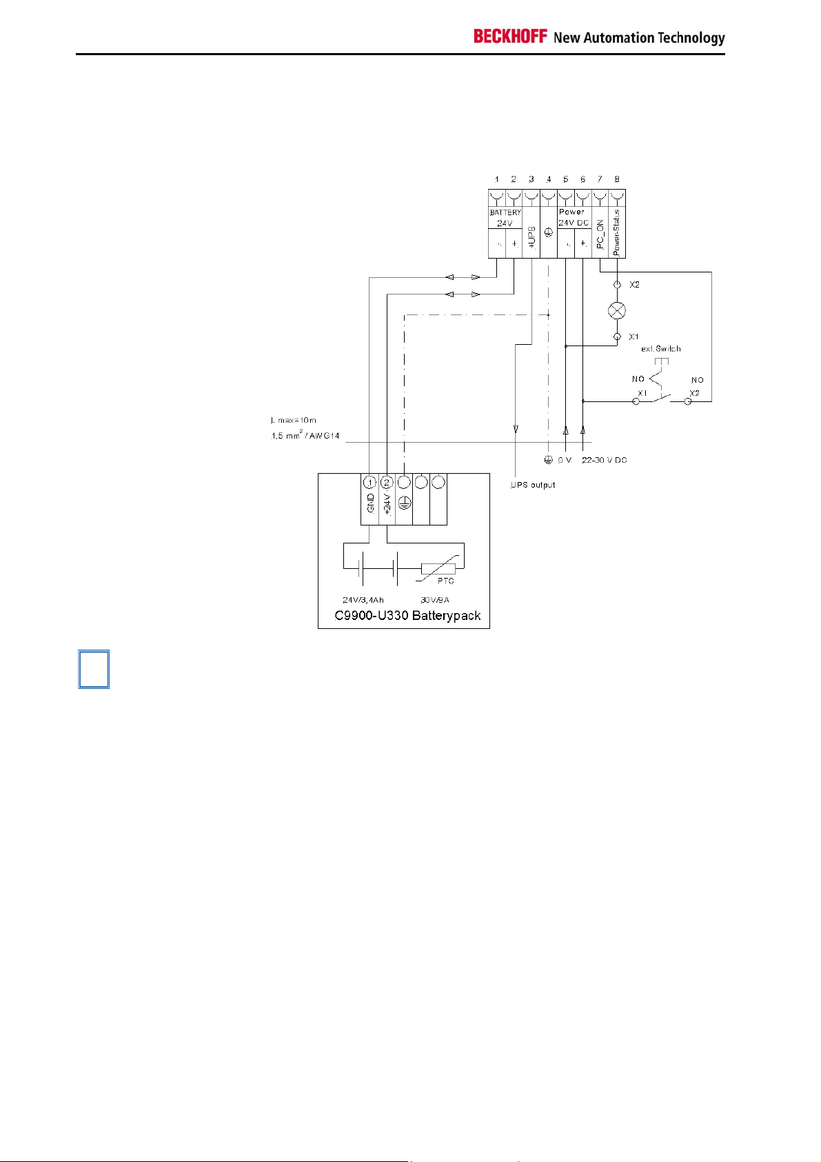
Wiring diagram power
supply and external circuit
Wiring diagram
Wiring according to the wiring diagram (the circuit of PC_ON and PowerStatus is symbolical):
i
Note
The battery pack can only be connected when the Industrial PC is provided
with an integrated UPS (order option).
18 C63xx
Page 21

Installation Instructions
Connecting devices
Warning
Fitted with the 24 VDC power supply unit:
Warning
The power supply plug must be withdrawn!
Please read the documentation for the external devices prior to connecting
them.
During thunderstorms, plug connector must neither be inserted nor
removed.
When disconnecting a plug connector, always handle it at the plug. Do not
pull the cable!
Connecting cables
The connections are located at the top of the Industrial PC and are
documented in the product description chapter.
When connecting the cables to the Industrial PC, proceed according to the
following sequence:
• Switch off all the devices that are to be connected.
• Disconnect all the devices that are to be connected from the power
supply.
• Connect all the cables between the Industrial PC and to the
devices that are to be connected.
• Connect all data transfer cables (if present) to the appropriate
plug-in receptacles of the data/telecommunication networks.
• Reconnect all devices to the power supply.
Check voltage rating and connect
1. Check that the external power supply is providing the correct
voltage.
2. Insert the power supply cable that you have assembled into the
Industrial PC's power supply socket. Then connect it to your
external 24 V power supply.
If a 24 V UPS is installed, the same type of rechargeable battery must
be used.
C63xx 19
Page 22

Operating Instructions
Operating Instructions
Switch on
Shutting down and
switching off
Warning
Warning
Please also refer to chapter General instructions.
Switching the Industrial PC on and off
The Industrial PC does not have its own mains switch. The Industrial PC
will start when the equipment is switched on, or when it is connected to the
power supply.
When the plant is switched off, or when it is disconnected from its power
supply, the Industrial PC will be switched off.
Control software such as is typically used on Industrial PCs permits various
users to be given different rights. A user who may not close software may
also not switch the Industrial PC off, since data can be lost from the hard
disk by switching off while software is running.
First shut down, then switch off the PC!
If the Industrial PC is switched off as the software is writing a file to the
hard disk, the file will be destroyed. Control software typically writes
something to the hard disk every few seconds, so that the probability of
causing damage by switching off while the software is running is very high.
When you have shut down the Industrial PC, you have to switch off power
supply for at least 10 seconds before rebooting the system.
After resetting power supply the PC will start booting automatically.
First switching on and driver installation
When you switch on the Industrial PC for the first time, the pre-installed
operating system (optional) will be started. In this case, all the required
drivers for any additional, optional hardware components ordered with the
PC will already have been installed.
If the PC was ordered without operating system, you have to install the
operating system and the driver software for any auxiliary hardware
yourself. Please follow the instructions in the documentation for the
operating system and the additional devices.
20 C63xx
Page 23

Operating Instructions
Maintenance
Danger
Danger
Please also refer to chapter General instructions.
Cleaning the Industrial PC
Switch off the Industrial PC and all connected devices, and disconnect the
Industrial PC from the power supply.
The Industrial PC can be cleaned with a soft, damp cloth. Do not use any
aggressive cleaning materials, thinners, scouring material or hard objects
that could cause scratches.
Replacing the battery on the motherboard
A used battery on the motherboard has to be replaced according to the
rules of the board manufacturer.
Danger of Explosion if battery is incorrectly replaced. Replace only with
same or equivalent type recommended by the manufacturer. Dispose of
used batteries according to the manufacturer's instructions.
Servicing
The Industrial PC requires no maintenance.
Shutting down
Dismantling the Industrial
PC
Observe national
electronics scrap
regulations
Disposal
The device must be fully dismantled in order to dispose of it. The housing
can be sent for metal recycling.
Electronic parts such as disk drives and circuit boards must be disposed of
in accordance with national electronics scrap regulations.
C63xx 21
Page 24

UPS Software Components (optional)
UPS Software Components (optional)
Installing the UPS driver
software
Installation
Beckhoff Information
System
For operating the power supply unit as a UPS, the UPS driver software and
the associated UPS driver must be installed on the Industrial PC.
On delivery of the Beckhoff Industrial PC with operating system the
software is already installed. Should the software not be installed on your
PC, the drivers can be installed from the driver CD provided.
Installation on the PC
To install the UPS driver software, execute file
Beckhoff_UPS_vx.xx.xx.exe from the subdirectory of UPS\… from the
CD provided on the Industrial PC (Driver-archive for the Industrial-PC,
C9900-S700-xxxx).
The program is self-extracting and will guide the user through the
installation routine.
Help files
The driver software comes with a detailed help function.
The help files can be called up either directly from the configuration register
by clicking the Help button, or under via Start > Programs > Beckhoff >
UPS software components.
22 C63xx
Page 25

Troubleshooting
Troubleshooting
Please also refer to chapter General instructions.
Fault correction
Fault Cause Procedure
Nothing happens after the Industrial
PC has been switched on
The Industrial PC does not boot
fully
Computer boots, software starts,
but control does not operate
correctly
CD access error Faulty CD
The Industrial PC functions only
partially or only part of the time, e.g.
no or dark picture, but disk drive
responds when switching on
No power supply to the Industrial
PC
Other cause
CD in the drive
Setup settings are incorrect
Other cause
Cause of the fault is either in the
software or in parts of the plant
outside the Industrial PC
Faulty disk drive
Defective components in the
Industrial PC
Check power supply cable
Call Beckhoff Service
Remove CD and press any
key
Check the setup settings
Call Beckhoff Service
Call the manufacturer of the
machine or the software
Check CD in another drive
Call Beckhoff Service
Call Beckhoff Service
C63xx 23
Page 26

Troubleshooting
Beckhoff Support & Service
Quote the project number
Beckhoff and their partners around the world offer comprehensive support
and service, guaranteeing fast and competent assistance with all questions
related to Beckhoff products and system solutions.
Beckhoff branches and partner companies
Please contact your Beckhoff branch office or partner company for local
support and service on Beckhoff products!
The contact addresses for your country can be found in the list of Beckhoff
branches and partner companies: www.beckhoff.com
You will also find further documentation
for Beckhoff components there.
Beckhoff Headquarters
Beckhoff Automation GmbH
Eiserstraße 5
33415 Verl
Germany
Phone: +49(0)5246/963-0
Fax: +49(0)5246/963-198
e-mail: info@beckhoff.com
Beckhoff Support
Beckhoff offers you comprehensive technical assistance, helping you not
only with the application of individual Beckhoff products, but also with wideranging services:
• worldwide support
• design, programming and commissioning of complex automation
systems
• training program for Beckhoff system components
Hotline:
Fax: +49(0)5246/963-9157
e-mail: support@beckhoff.com
+49(0)5246/963-157
Beckhoff Service
The Beckhoff service center supports you in all matters of after-sales
service:
• on-site service
• repair service
• spare parts service
• hotline service
Hotline:
Fax: +49(0)5246/963-479
e-mail: service@beckhoff.com
If servicing is required, please quote the project number of your product.
+49(0)5246/963-460
24 C63xx
Page 27
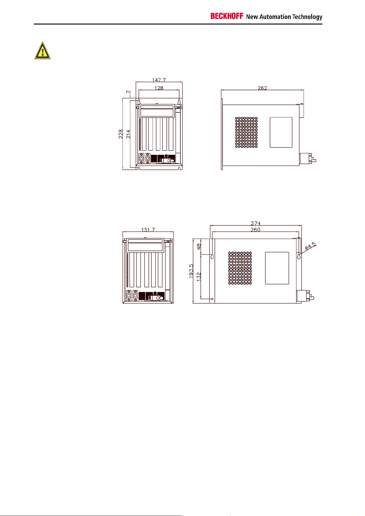
Assembly dimensions
Assembly dimensions
Warning
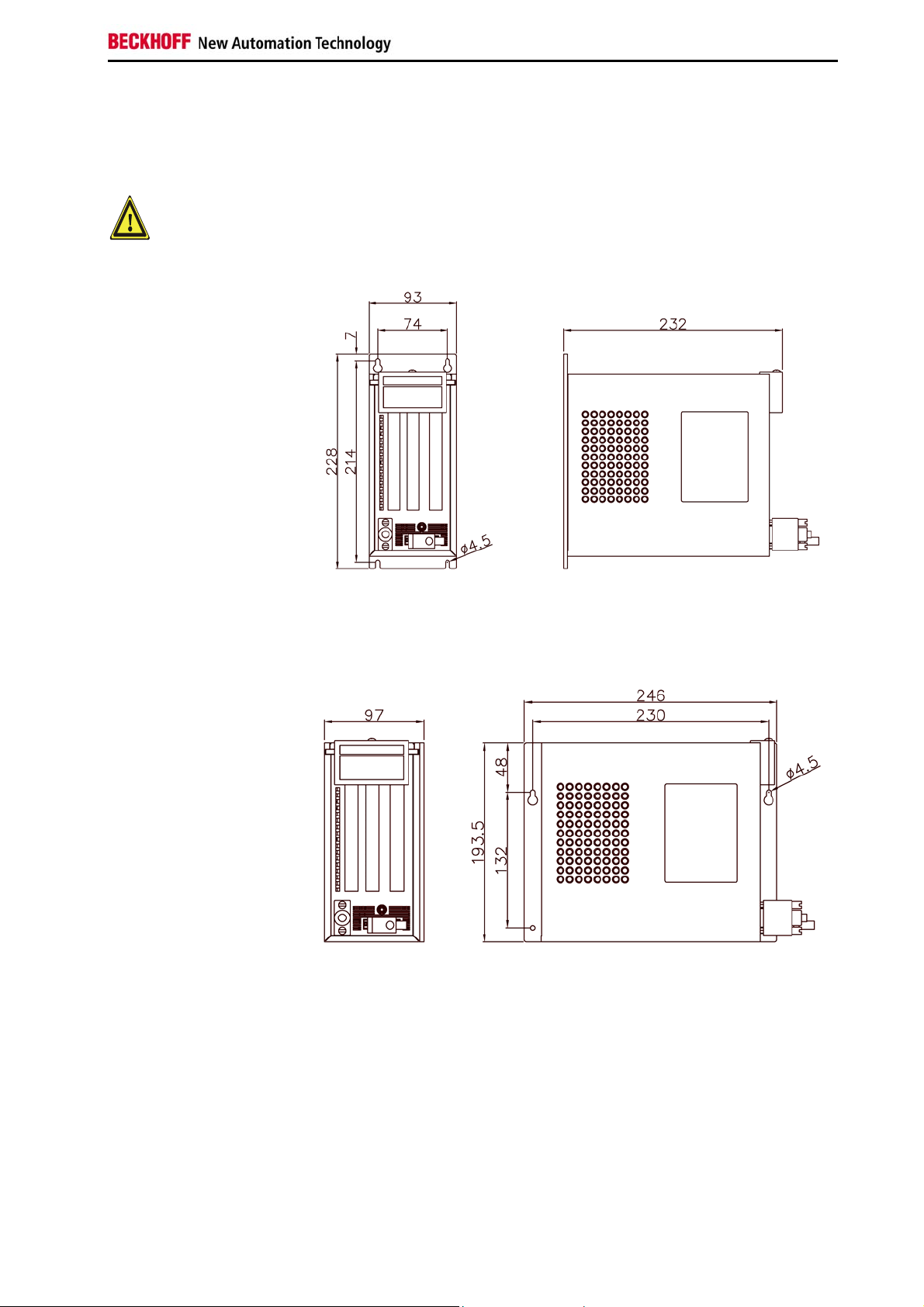
Industrial-PC C6320
Mounting plate at the
rear panel
Mounting plate at the
side panel
The following pages show diagrams of the Industrial PCs, with dimensions
in mm.
The assembly of the unit must take place with the orientation diagrammed
here.
front view side view
front view side view
C63xx 25
Page 28

Assembly dimensions
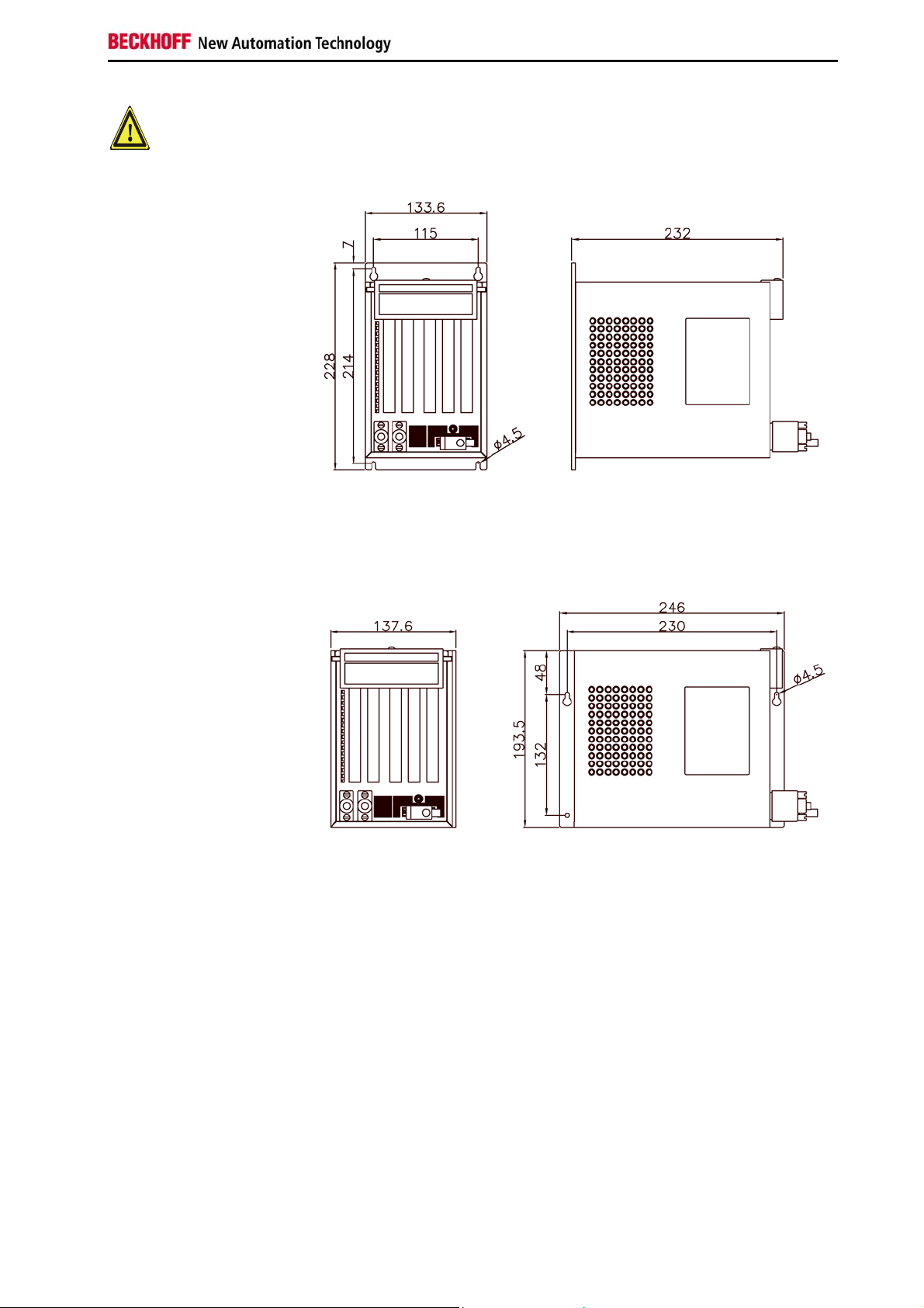
The assembly of the unit must take place with the orientation diagrammed
here.
Warning
Industrial-PC C6325
Mounting plate at the
rear panel
front view side view
Mounting plate at the
side panel
front view
side view
26 C63xx
Page 29

Assembly dimensions
The assembly of the unit must take place with the orientation diagrammed
here.
Warning
Industrial-PC C6330
Mounting plate at the
rear panel
Mounting plate at the
side panel
front view side view
front view
side view
C63xx 27
Page 30

Assembly dimensions
The assembly of the unit must take place with the orientation diagrammed
here.
Warning
Industrial-PC C6335
Mounting plate at the
rear panel
front view side view
Mounting plate at the
side panel
front view
side view
28 C63xx
Page 31
Assembly dimensions
The assembly of the unit must take place with the orientation diagrammed
here.
Warning
Industrial-PC C6340
Mounting plate at the
rear panel
front view side view
Mounting plate at the
side panel
front view side view
C63xx 29
Page 32
Assembly dimensions
The assembly of the unit must take place with the orientation diagrammed
here.
Warning
Industrial-PC C6350
Mounting plate at the
rear panel
front view side view
Mounting plate at the
side panel
front view
side view
30 C63xx
Page 33

Appendix
Appendix
Technical data
Industrial-PC C6320
Dimensions (W x H x D): 93 x 196 x 226 mm (without mounting plate)
Weight: 4,0 kg (basic configuration)
Industrial-PC C6325
Dimensions (W x H x D): 133 x 196 x 226 mm (without mounting plate)
Weight: 6,0 kg (basic configuration)
Industrial-PC C6330
Dimensions (W x H x D): 107 x 196 x 226 mm (without mounting plate)
Weight: 4,6 kg (basic configuration)
Industrial-PC C6335
Dimensions (W x H x D): 147 x 196 x 226 mm (without mounting plate)
Weight: 6,6 kg (basic configuration)
Industrial-PC C6340
Dimensions (W x H x D): 134 x 196 x 226 mm (without mounting plate)
Weight: 4,5 kg (basic configuration)
Industrial-PC C6350
Dimensions (W x H x D): 148 x 196 x 226 mm (without mounting plate)
Weight: 5,1 kg (basic configuration)
Do not use the PC in areas
of explosive hazard
The Industrial PC may not be used in areas of explosive hazard.
The following conditions must be observed during operation:
Environmental conditions
Ambient temperature: 0 to 55°C
Atmospheric humidity: Maximum 95%, non-condensing
Shock resistance Sinusoidal vibration:
(EN 60068-2-6)
10 to 58 Hz: 0.035 mm
58 to 500 Hz: 0.5 G (~ 5 m/ s2)
During reading of CD-ROM: 10 to 58 Hz: 0.019 mm
58 to 500 Hz: 0.25 G (~ 2.5 m/ s2)
Impact:
(EN 60068-2-27/ -29) 5 G (~ 50 m/ s²), duration: 30 ms
During reading of CD-ROM: 5 G (~ 50 m/ s²), duration: 11 ms
Protection class
Power supply
power pack
24 V
DC
Electromagnetic
Compatibility (EMC)
Transport and storage
Protection class:
Supply voltage: 22–30V V
IP20
DC
Power consumption: C6320-0030: approx. 70 W
(basic configuration) C6325-0030: approx. 70 W
C6330-0030: approx. 75 W
C6335-0030: approx. 75 W
C6340-0030: approx. 70 W
C6350-0030: approx. 75 W
C6320-0040: approx. 95 W
C6325-0040: approx. 95 W
C6330-0040: approx. 100 W
C6335-0040: approx. 100 W
C6340-0040: approx. 95 W
C6350-0040: approx. 100 W
When operated with UPS: additional 30 W (while charging)
additional 44 W (with UPS-output)
Interference resistance: according to EN 61000-6-2
Emitted resistance: according to EN 61000-6-4
The same values for atmospheric humidity and shock resistance are to be
observed during transport and storage as in operation. The shock
resistance during transport can be improved by means of suitably packing
the Industrial PC. The ambient temperature during storage and transport
must be between -20°C and +65°C.
C63xx 31
Page 34

Appendix
Approvals
FCC: Federal Communications Commission Radio Frequency Interference Statement
FCC Approval for USA
This equipment has been tested and found to comply with the limits for a
Class A digital device, pursuant to Part 15 of the FCC Rules. These limits
are designed to provide reasonable protection against harmful interference
when the equipment is operated in a commercial environment. This
equipment generates, uses, and can radiate radio frequency energy and, if
not installed and used in accordance with the instruction manual, may
cause harmful interference to radio communications. Operation of this
equipment in a residential area is likely to cause harmful interference in
which case the user will be required to correct the interference at his own
expense.
FCC Approval for Canada
FCC: Canadian Notice
This equipment does not exceed the Class A limits for radiated emissions
as described in the Radio Interference Regulations of the Canadian
Department of Communications.
32 C63xx
 Loading...