

Page 1
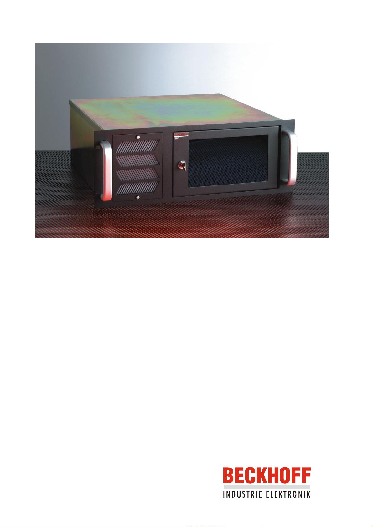
Beckhoff Industrial PC C5002
Operating Instructions
Version: 1.0
Last change: 05.06.2000
Page 2

Page 3

Table of contents
Safety instructions 3
The operator’s duties 3
The user’s duties 4
Appropriate Use 4
Connections 5
Power supply 5
Serial interfaces 6
Parallel interface 6
PS/2 Connections 6
USB Interfaces 6
Video connection 6
Additional plug-in cards (optional) 6
Operation of the Industrial PC 7
Servicing and maintenance 8
Changing the Air Filter 8
Cleaning 8
Eiserstraße 5 / D-33415 Verl / Phone 05246/963-0 / Fax 05246/963-149
Table of contents 2
Disposal 9
Faults 9
C5002
Page 4

INDUSTRIE ELEKTRONIK Eiserstraße 5 / D-33415 Verl / Phone 05246/963-0 / Fax 05246/963-149
Operating Instructions Slide-in PC C5002 3
Industrial PC C5002 Operating Instructions
Safety instructions
Only switch the PC off after
closing the software
Switch off all parts of the
equipment, then uncouple
the field bus
Do not open the power
supply unit while voltage is
applied
Do not exchange any parts
when under power
Before the Industrial PC is switched off, software that is running must
be properly closed.
Otherwise it is possible that data on the hard disk is lost. Please read the
section on “Switching off”.
Before opening the housing of the PC, and whenever the PC is being
used for purposes other than plant control, such as during functional
tests following repair, all parts of the equipment must first be
switched off, after which the Industrial PC can be uncoupled from the
plant.
Pulling out the field bus connection plug uncouples the PC.
Items of equipment that have been switched off must be secured
against being switched on again.
The Industrial PC’s power supply unit must be supplied with
230 V / 115 V AC.
The supply voltage must be switched off before the power supply unit
housing is opened.
When components are being fitted or removed, the supply voltage
must be switched off.
National regulations
depending on the
machine type
Test regulations
Only trained personnel may
open the PC’s
Software knowledge
Fitting work on the PC can result in damage:
if metal objects such as screws or tools fall onto operating circuit
boards.
if connecting cables internal to the PC are removed or inserted
during operation.
if plug-in cards are removed or inserted when the PC is switched
on.
The operator’s duties
Depending on the type of machine and plant in which the Industrial PC is
being used, there will be national regulations for the control of such
machines and plant that the operator must observe. These regulations
cover, amongst other things, the intervals between inspections of the
controller.
The operator must initiate such inspections in good time.
The operator is responsible for ensuring that only trained electrical staff
opens the housing of the Industrial PC.
Every user must be familiar with any of the functions of the software
installed on the PC that he can reach.
Make operating instructions
accessible
The contents of these operating instructions must be known by every user
of the Industrial PC and by every fitter who installs, removes or opens the
device.
C5002
Page 5

INDUSTRIE ELEKTRONIK Eiserstraße 5 / D-33415 Verl / Phone 05246/963-0 / Fax 05246/963-149
4 Operating Instructions Slide-in PC C5002
Procedure in the event of a
fault
In the event of a fault in the Industrial PC, appropriate measures can be
determined with the aid of the list in the “Faults” section.
The BECKHOFF Service number:
for Germany: 05246/963-460
international: 0049-5246/963-460
The user’s duties
Read the operating
instructions
Software knowledge Every user must be familiar with any of the functions of the software
Every user of the Industrial PC must have read these operating
instructions.
installed on the PC that he can reach.
Appropriate Use
The C5002 Industrial Computer is intended for fitting into 19 inch racks for
industrial application in machine and plant control engineering. A complete
IBM compatible PC with a standard ATX motherboard, hard disk and floppy
drive is built into a 7-slot plug-in unit.
Do not use the PC in areas
of explosive hazard
The Industrial PC may not be used in areas of explosive hazard.
The following technical data must be observed during operation:
Environmental conditions Ambient temperature: 0 to 55 °C
Atmospheric humidity: Maximum 95 %, non-condensing
Shock resistance Housing & chassis: Vibrations 5 G at 10..55 Hz
Impact resistance 30 G
Disk drive: Vibrations 0.5 G at 5..500 Hz
Impact resistance 5 G
Hard disk: Vibrations 0.5 G at 17..500 Hz
Impact resistance 10 G
Protection type: IP60
Power supply
230/115 V AC mains power
supply unit
Compatibility Resistance to interference: according to EN 50082-2
Transport and storage
Supply voltage: Switchable between
115 V 60 Hz
230 V 50 Hz
Max. power consumption: 64 W for the basic version
The same values for atmospheric humidity and shock resistance are to be
observed during transport and storage as in operation. The shock
resistance during transport can be improved by means of suitably packing
the Industrial PC. The ambient temperature during storage and transport
must be between –20 °C and +60 °C.
C5002
Page 6

INDUSTRIE ELEKTRONIK Eiserstraße 5 / D-33415 Verl / Phone 05246/963-0 / Fax 05246/963-149
Operating Instructions Slide-in PC C5002 5
Connections
Rear view of the basic
version of the C5002
Industrial PC
Mains power supply unit
Power supply
The C5002 Industrial PC has a standard ATX 230/115 V 50/60 Hz power
supply.
Power supply plug On/off switch
Current loading capacity
230 V power supply unit
Mains power supply
voltage switch
Output voltages of the
115/230 V power supply unit maximum
+3,3 V
+12 V
-12 V
Current loading
+5 V
-5 V
22 A
0,3 A
14 A
8 A
0,8 A
C5002
Page 7

INDUSTRIE ELEKTRONIK Eiserstraße 5 / D-33415 Verl / Phone 05246/963-0 / Fax 05246/963-149
6 Operating Instructions Slide-in PC C5002
Setting the mains voltage
Changing from 230 V to
115 V
RS 232
COM1 - COM2
Mains voltages of 230 V 50 Hz or 115 V 60 Hz may be set. In order to do
this the slide switch (see photos below) is moved to the appropriate
position with the aid of a small screwdriver. The voltage that has been set
can be read.
Changing from 115 V to
230 V
Serial interfaces
The basic version of the C5002 Industrial PC has two serial interfaces,
COM1 and COM2, using the type RS 232, which are brought to a 9 pin
SUB-D pin connector.
Printer
LPT1
PS/2
USB1 – USB2
Video
Type plate
Parallel interface
The parallel interface corresponds to the Centronics standard, and is
addressed by the software as LPT1.
PS/2 Connections
The upper PS/2 connector allows a PS/2 mouse to be used, while a PC
keyboard can be connected to the lower PS/2 connector.
USB Interfaces
Both USB interfaces provide for the connection of any peripheral devices
with USB connections.
Video connection
A 15-pin SUB-D socket allows a VGA monitor to be
connected.
Additional plug-in cards (optional)
There is a type plate on the rear of the PC which provides information
about the hardware configuration of the PC at the time it was supplied.
C5002
Page 8

INDUSTRIE ELEKTRONIK Eiserstraße 5 / D-33415 Verl / Phone 05246/963-0 / Fax 05246/963-149
Operating and LED's
behind the front cover
Operating Instructions Slide-in PC C5002 7
Operation of the Industrial PC
The front of the PC has a lockable front cover, behind which operating
elements and LED's are located. There is a number on the lock.
If the key is lost, the number on the lock can be used to order a
replacement.
Reset key
LED's
Keyboard switch
Switching on
Reset key
Switching off
KeyLock
LED's
On/off switch
The Industrial PC has its own ON switch (see photo above), although this
can optionally be configured to have no function.
At the top left behind the front panel there is a reset button with which the
system can be re-booted (see photo above).
Control software such as is typically used on Industrial PCs permits various
users to be given different rights. A user who may not close the software
must also be unable to switch the Industrial PC off, since data can be lost
from the hard disk by switching off while the software is running.
If the Industrial PC is switched off while the software is writing a file to the
hard disk, this data can be damaged. Control software generally writes files
such as logs to the disk of its own accord at intervals of just a few seconds,
which means that the probability of damage is quite high if the computer is
switched off while the software is running.
A keyboard switch above the mains switch allows a connected PC
keyboard to be switched off.
There are two LED's behind the front cover. The yellow LED indicates hard
disk activity, while the green LED indicates that the power is switched on.
Disk drive
C5002
Page 9

INDUSTRIE ELEKTRONIK Eiserstraße 5 / D-33415 Verl / Phone 05246/963-0 / Fax 05246/963-149
8 Operating Instructions Slide-in PC C5002
Servicing and maintenance
Changing the Air Filter
The PC has an air filter that must be changed at regular intervals. The
Usable life
filter's usable life depends on the number of operating hours and on the
amount of dust in the surrounding air.
If it is not possible to determine the need to change the filter with a visual
check, then if the air is very dusty the filter must be changed once a month.
Caution
Item number
View of the fan cover
If a necessary filter change is omitted components within the computer can
be damaged or destroyed through overheating.
The ordering/item number for replacement filters is: C9900-Z210
Fast closing
screws
Fan cover
Filter changing procedure
Caution!
First switch the Industrial
PC off
Follow these instructions when changing the air filter:
1. First use a screwdriver to turn one of the fast closing screws (see
photo above) 90 degrees in any direction.
2. Hold the fan cover in place while you do the same with the second
screw. Failure to follow this procedure can result in injury to persons or
damage to objects situated underneath the PC or to the cover itself as
it falls.
3. The fan cover is not fixed to the housing in any other way, and can be
drawn forwards to remove it.
4. The dust filter can easily be pulled out and exchanged.
5. Return the filter cover to its original position on the housing.
6. Press and turn both the fast-closing screws 90 degrees in any direction
with a screwdriver.
Cleaning
The front of the Industrial PC can be cleaned with a soft, damp cloth. Do
not use any aggressive cleaning materials, thinners, scouring material or
hard objects that could cause scratches. The Industrial PC must be
switched off for cleaning.
C5002
Page 10

INDUSTRIE ELEKTRONIK Eiserstraße 5 / D-33415 Verl / Phone 05246/963-0 / Fax 05246/963-149
Operating Instructions Slide-in PC C5002 9
Disposal
Remove the Industrial PC
and dismantle it Observe
national electronics scrap
regulations
In order to dispose of the device, it must be removed and fully dismantled.
The housing can be sent for metal recycling. Electronic parts such as disk
drives and circuit boards must be disposed of in accordance with national
electronics scrap regulations.
Faults
Quote the project number If servicing is required, please quote the project number of your PC.
fault Cause Procedure
No function after the Industrial PC
has been switched on
The Industrial PC does not boot
fully
No power supply. 1. Measure voltage at
connection, check plug
wiring.
2. Call Beckhoff Service.
Floppy disk in drive.
Hard disk damaged (e.g. by
switching off while software
running).
Remove floppy disk and
press any key
Call Beckhoff Service.
Incorrect setup.
Other cause.
Computer boots, software starts,
but control does not operate
correctly
Error during floppy disk access Faulty floppy disk.
Cause of the fault is either in the
software or in parts of the plant
outside the Industrial PC.
Faulty disk drive.
Check the set-up. If
necessary, call the Beckhoff
service department
Call Beckhoff Service.
Call the manufacturer of the
machine or the software.
Check disk in another PC.
Call Beckhoff Service.
C5002
 Loading...