

Page 1
Vista®
basic
Service
Manual
950971
Rev
A
(5/04)
Version
Software:
1.0
English
IFVA23002.......
Page 2
This
The
complete
the
foliowing
Service
Manual
Service
pages:
is
valid
Manual
for
contains
Voltages
Vistabasic
Vista
basic
Page
0-1
to
Page
1-1
to
Page
2-1
to
Page
3-1
to
Page
4-1
to
Page
5-1
to
Page
6-1
to
Page
7-1
to
Page
8-1
to
Page
9-1
to
Page
10-1
Page
A-1
to
100 V /
110 V /
120
V,
switchable:
....................................
.
Page
0-8
Page
1-12
Page
2-6
Page
3-12
Page
4-20
Page
5-2
Page
6-2
Page
7-2
Page
8-6
Page
9-2
to
Page
10-2
Page
A-4
637-102
637-202
Vista
basic
950971
Rev A (5/04)
Page 3
Table
of
Contents
Important
General
System
Information
Overview
Information
on
this
Manual
Service
Work
Technical
Current
Revision
Non-Liability
ISO
Repair
Spare
Setting
Technical
Entry
Ordering
Return
Service
Safety
Translation
Design
Operation
Function
Voltage
Signal
Mains
Battery
Alarm
Pump
Computer
Braun
Internal
Language
Accessories
Safety
Versions
Service
9000
ff/EN 46
and
by
Trained
Parts
Off
Training
for
the
of
of
Spare
Hotline
Officer
Supply
Table
Operation
Operation
Circuit
Unit
fluid
Assignment
Groups
Inspection
and
Spare
Flow
Interface
manager
Inspections
000
ff
only
Technicians
Test
Equipment
Product
Training
Parts
and
Parts
Chart
system
Test
(fm
Equipment
system)
Page
Page
Page
Page
Page
Page
Page
Page
Page
Page
Page
Page
Page
Page
Page
Page
Page
Page
Page
Page
Page
Page
Page
Page
Page
Page
Page
Page
Page
Page
Software
Service
Ünit
Elements
Vista
basic
Program
950971
Rev A (5/04)
Software
Approved
Error
Software
Structure
Additional
Start / Quit
Unit
History
Test
Unit
Calibration
Mains
Battery
Door
Pump
Pump
Update
Software
Messages
Default
of
the
Functions
Inserted
the
Data
Data
Madifications
Fuses
Lock
Cover
Housing
Versions
and
Alarms
Values
Service
Service
Plug
Service
Program
with
Program
Page
Page
Page
Page
Page
Page
Page
Page
Page
Page
Page
Page
Page
Page
Page
Page
Page
Page 4
Table
of
Contents
Checks
Maintenance
Technical
Procedurat
Test
Spare
after
Equipment
Parts
Repair
Safety
Inspection
Instructions
and
List
for
Special
TSI
Inspection
Tools
Housing
Controller
Rear
Front
Pump
Occlusion
Air
Operating
Barcode
Frame
1.
2.
3.
4.
Test
Unit
„Colours
Miscellaneous
Software
and
Handle
Board
Panel
Panel
Unit
Sensor
Sensor
Unit
Label
with
Seal
Visual
Inspection
Electrical
Functional
Pump
Safety
per
IEOEN60
Inspection
Unit
Inspection
Equipment
Elements
Update Page
Inspection
601-1
and
Special
as
Tools
Page
Page
Page
Page
Page
Page
Page
Page
Page
Page
Page
Page
Page
Page
Page
Page
Page
Page
Page
Page
Page
4-5
4-6
4-7
4-10
4-
12
4-14
4-17
4-18
4-19
4-19
5-1
6-1
7-1
8-1
8-1
8-2
8-3
9-1
10-1
10-2
10-2
10-2
n
)
-
Appendix
0-4
ESD
Recommendations
Workstation
Revision
Current
Order
Service-
Documentation
Information
Form Page
Vista
basic
Page
Page
Page
Page
950971
A-1
A-1
A-2
A-2
A-2
Rev A (5/04)
Page 5
Important
The
following
notes
should
Information
be
observed:
on
this
Manual
Service
Technical
Current
Work
Versions
Safety
Inspections
The present
this
Service
- © have
- © areinctuded
- © possess
-
B.
Braun
spections,
version
-
-
-
This
was
must
the
manual
manual
does
tasks
may
received
Braun
the
and
fulfil
the
personal
also
or to
of
the
manual,
the
TS!
requires
served
the
manuais
depending
called
up
which
case
of
an
service
connector
manual
written.
index
always
number
version
Technical
be
recommends
is
for
your
not
authorize
only
be
executed
appropriate
in
the
revision
necessary
perform
are a reference
on
inappropriate
expected.
test
requirements
training
at
least
as:
that
the
the
unit
type,
may
leadto a dangerous
may
be
corresponds
changes,
The
on the
title
information
the
training
service
equipment
the
instructions
for
operation.
necessary.
especially
state
page.
only.
performance
by
persons,
on
(training
on
the
steps
indicated
in
measurements
the
service
Furthermore, a special
to
the
state
software
of
the
revision
The
possession
of
service
who
the
system
and
mechanical
and
knowledge).
technical
in
the
manuals
program
unit
conditionin
when
modifications
is
indicated
from
safety
the
current
are
must
the
manual
of
work,
B.
aids,
in-
ob-
be
the
by
Revision
Service
Non-Liability
Vista
basic
950971
Rev A (5/04)
The
possession
sion
in
the
service
after:
-
technical
- © a
written
(incurred
B.
Braun
juries
to
-
the
use
respondtothe
vice
-
the
service
-
technicians
course
of
this
manual
revision
Melsungen
persons,
tasks
non-inclusion
service.
training
order
placed
costs),
property
of a wrong
revision
who
for
the
specific
by
AG
manual,
of
have
B.
with
does
damages
state
the
not
does
You
Braun
not
service
B,
not
automatically
will
be
included
Melsungen
the
sales
department
assume
any
or
other
damages
or a manual
for
maintenance,
participated
Braun
which
technician
in a technical
unit.
mean
inclu-
in
the
revision
or
of
B.
Braun
responsibility
caused
does
repair,
and
in
the
for
not
revision
training
in-
by:
cor-
ser-
Page 6
Z
ISO
Important
9000
ff/EN
46
Information
000
ff
on
this
Manual
B.
Braun
001.
46
The
Vista
IEC/EN60601-
cording
is
certified
This
certification
basic
complies
2-24
to
the
EC
in
accordance
also
with
standards
directive
with
includes
the
IEC/EN60601-1
and
is
certified
93/42/EC.
DIN
ISO
9001
maintenance
and
with
the
and
and
CE
DIN
EN
service.
label
ac-
Repair
by
Trained
Spare
Parts
Setting
and
Inspection
Technicians
and
Off
Test
only
Equipment
Training
manual
structions
must
An
"Checks
Only
tamper
completely.
instructions,
The
test
works
Additional
may
does
on
be
observed.
electrical
after
use
original
with
inspection
equipment.
of
B.
Braun.
notes
Gives
additional
steps.
Is
system
E
used
for
working
or to a connected
only
be
performed
not
authorize
electrostatic
check
must
be
Repair”
bg.
spare
assembly
The
personnel
groups
spare
parts
Original
test
Further
and
warnings
or
special
steps
which
by
B.
the
performance
sensitive
performed
5-1).
parts
from
which
required
is
responsible
equipment
information
are
notes
on
may
device.
Braun.
The
of
components
following each
the
manufacturer.
can
only
are
listed
'
for
the
can
be
is
available
set
off
as
information
FES
result
in
damage
possession
repairs.
The
(ESD
standards)
repair
Do
be
exchanged
in
the
repair
calibration
calibrated
upon
request.
follows:
and
working
to
the
of
the
in-
(see
not
of
the
at
the
unit,
IS
USED
INJURY.
FOR
WORKING
STEPS
WHICH
MAY
Vista
RESULTIN
basic
950971
PERSONAL
Rev A (5/04)
Page 7
General
Information
Technical
Entry
for
Ordering
Return
Technical
Training
the
of
of
Spare
Service
Product
Spare
Parts
Support
Training
Parts
and
Test
Equipment
B.
Braun
Medical
1601
Wallace
Carrollton,
Responsibility
B.
Braun
Only
B.
1
800
B.
1601
Carrollton,
Carrollton,
Tel: 1 800
via
Braun
627-PUMP
Braun
Wallace
Texas
Medical
the
responsible
Medical
Medical
Texas
Texas
241-2243
Inc.
Drive,
75006
Inc.,
Inc.
(7867)
Inc.
Drive,
75006
75006
Suite
150
Service
representative
Suite
150
Tel.:
Fax:
1
800
972
241-2243
245-1612
Vista
basic
950971
Rev A (5/04)
Page 8
For
your
General
notes:
Information
0-8
-
Vista
basic
950971
Rev A (5/04)
Page 9
System
Overview
Design
LCD
Handle
Door
Display
Lock
Guide
for
Short
Pole
Clamp
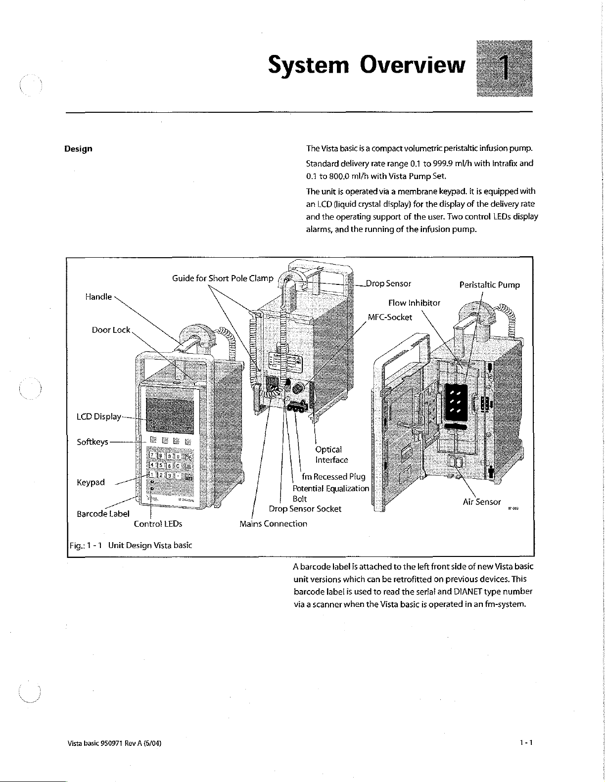
The
Vista
Standard
0.1
to
800.0
The
unit
is
an
LCD
(liquid
and
the
operating
alarms,
and
basic
is a compact
delivery
ml/h
with
operated
crystal
the
running
Drop
MFC-Socket
volumetric
rate
range
0.1
Vista
Pump
via a membrane
display)
support
of
of
Sensor
Flow
the
Inhibitor
to
999.9
Set.
keypad.
for
the
display
the
user.
infusion
na
peristaltic
Two
infusion
ml/h
with
It
is
of
the
control
pump.
ete
Peristaitic
pump.
Intrafix
equipped
delivery
LEDs
Pump
and
with
rate
display
Softkeys
Keypad
Barcode
Fig.:
1-1
Label
Unit
Design
Control
LEDs
Vista
basic
Mains
Potential
D
Sol
Top
sensor
Connection
A
unit
barcode
via a scanner
Optical
Interface
fm
Recessed
Equalization
sock
Socket
barcode
versions
label
P
lug
label
which
is
when
is
attached
can
used
to
the
to
the
be
retrofitted
read
the
Vista
basic
left
front
on
serial
and
is
operated
Air
side
of
previous
DIANET
in
Sensor
new
Vista
devices.
type
number
an
fm-system.
won
basic
This
Vista
basic
950971
Rev A (5/04)
Page 10
System
Overview
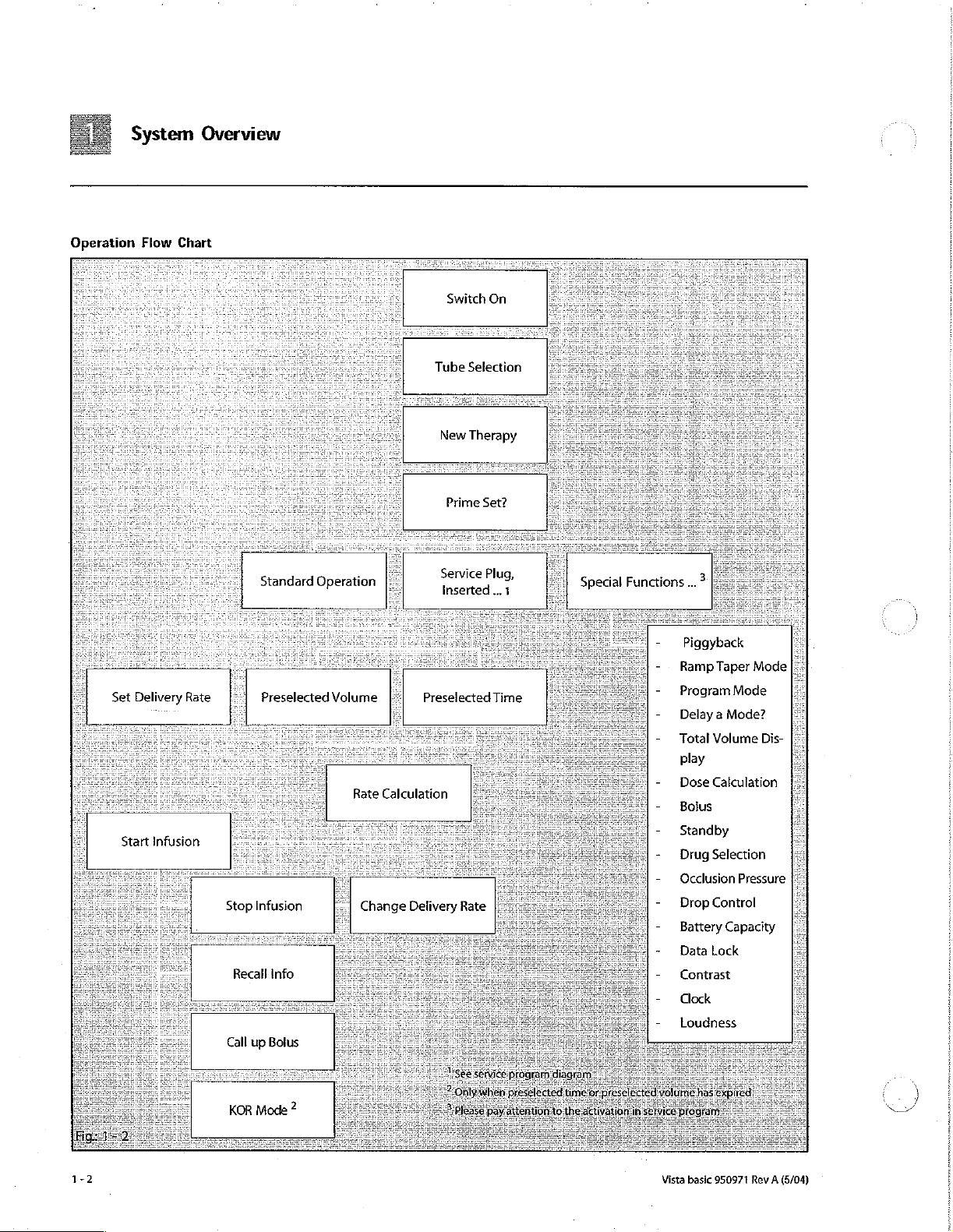
Operation
Flow
Chart
Standard
Operation
Switch
Tube
Selection
New
Therapy
Prime
Service
Inserted
On
Set?
Plug,
...
+
Special
Functions...
3
Piggyback
Ramp
Taper
Mode
Set
Start
Delivery
infusion
Rate
‘|
Stop
Recall
Call
KOR
up Bolus
Preselected
Infusion
info
Mode
2
Volume
Rate
:
Change
||
Preselected
Calculation
.
Delivery
Ses
Rate
Time
Program
Delay à Mode?
Total
play
Dose
Bolus
Standby
Drug
Occlusion
Drop
Battery
Data Lock
Contrast
Clock
Loudness
Mode
Volume
Calculation
Selection
Pressure
Control
Capacity
Dis-
|:
トーン
a
1-2
Vista
basic
950971
Rev A (5/04)
Page 11
System
See
Instructions
for
Use
for
detailed
Overview
information.
M
Vista
basic
950971
Rev A (5/04)
Page 12
System
Overview
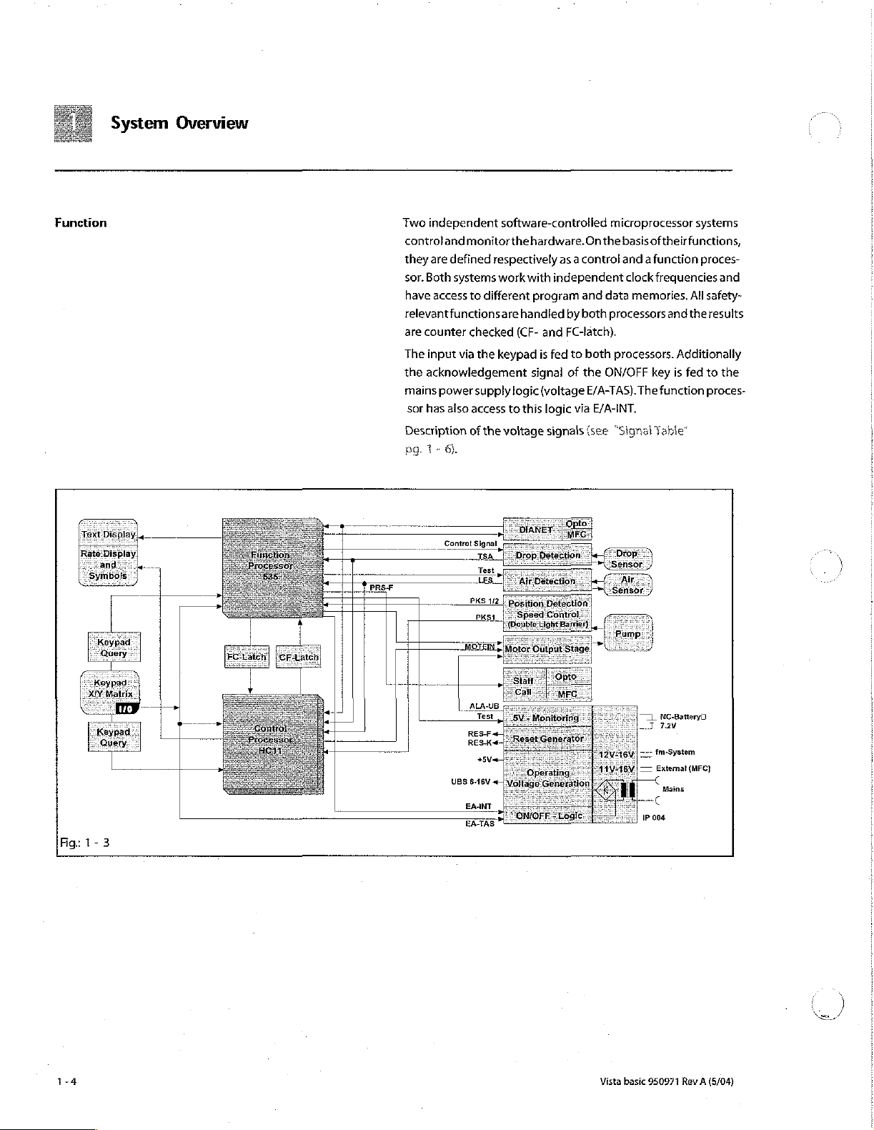
Function
Two
independent
control
and
they
are
defined
sor.
Both
systems
have
access
relevant
functions
are
counter
The
input
the
acknowledgement
mains
power
sor
has
also
Description
29.
1-5).
Controt
software-controlled
monitor
via
respectively
work
to
different
are
checked
the
keypad
supply
access
of
the
voltage
Signal
Test
the
(CF-
logic
to
hardware.
with
independent
program
handled
and
is
fed
signal
(voltage
this
logic
signals
microprocessor
On
the
as a control
and
data
by
both
processors
FC-latch).
to
both
processors.
of
the
ON/OFF
E/A-TAS).
via
E/A-INT,
(see
“Sign:
basis
of
their
and a function
clock
frequencies
memories,
and
Additionally
key
is
The
function
ile
systems
functions,
proces-
and
All
safety-
the results
fed
to
the
proces-
Fig:
1-3
1-4
UBS
+5V
6-16V
EAANT
EA-TAS
71
=]
ーー-
一
—
IP
Vista basic
NC-BatteryD
TN
fm-System
Емета
Mains
004
950971
Rev A (5/04)
(МЕС)
Page 13
System
Overview
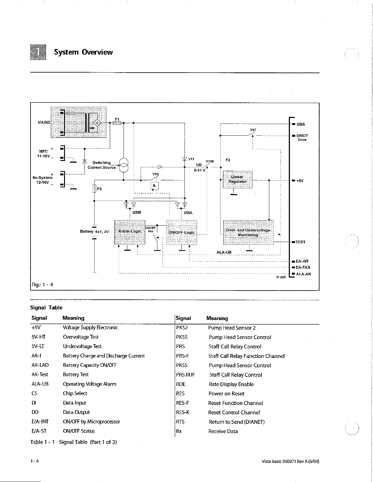
Voltage
Supply
The
voltage
FM
plug
(14 V connection
MFC
connector
ternal
7.2 V NiCD
versions:
voltage
Avoltage
tification.
unit
MFC
the
OFF switch
+5V
nel
monitors
checked
stepper
The
of
switching
on
The
ply
delay
tor
The
when
alarm
is
ON/OFF
test
is
ing
230
has a tolerance
of
This
supply.
or
FM
internal
supplies
microprocessor
the
during
motor
transistor
an
alarm
function
test.
circuit
voltages
switch:
V10b.
alarm
logic
the
buzzer
activated
key.
of
the
performed,
pulses
supply
is
generated
(11
to
16
V)
battery.
V,
220 / 230 / 240 V and
of + 10%
11
Vto
18
Vis
voltage
is
fed
This
is
also
valid
plug.
The
FET
V10
voltage
supply.
for
the
operating
the
complete
system. A window
+5V
for
undervoltage
switch-
on.
and
the
UMOT,
V47
switches
the
motor
is
of
the
has
two
separate
UBA
and UBB. The
off. A follow-up
(operating voltage
unit
is
running
and
drive
are
and
the
voltage
The
alarm
latch
voltage
monitoring,
The
voltage
fed
to
the
logic.
either
to
the
fluid
manager
and
as
an
The
mains
module
to — 15
available
electronics
The
switched
transistor
also
supply
The
to
the
battery
for
an
external
switches
The
transistor
voltages
or
operating
the
stepper
the
operating
assembly
ON/OFF
charging
UBB)
and
activates
driven
supply
is
is
reset
motor
is
maintained
alarm
after
off
is
switched
circuit
directly
from
mains,
via
the
system),
internal
supply
is
100 / 110 / 120
%.
transformation
charge
12 V supply
between
VIOb
UBS,
UMOT
including
comparator
overvoltage.
voltage
motor
voltage
by
V47.
checked
groups
with
circuit
has a retriggerable
circuit
is
an RS
the
by
UBB.
The
simultaneously. A function
and
latch
is
also
or
via
via
the
available
the
during
drives
alarm
on
by
in
V.
The
and
circuit
and
from
the
external
works
as
an
and
+5V.
double
constantly
The
function
UBS
supplies
drive.
UMOT.
In
Additionally
the
switch-
separate
the
transis-
latch.
This
circuit.
ON/OFF
by
pressing
alarm
activation
cyclic
self-hold-
activated.
the
in-
three
rated
rec-
the
the
and
ON/
The
chan-
is
the
case
the
sup-
is
set
The
circuit
the
Vista
basic
950971
Rev A (5/04)
1-5
Page 14
MAINS:
+
MFC
11-16\
_
fm-System
+
1246V
System
Overview
Switching
Current
Source
Battery:
6x1,
2V
+8V
Fig:
1-4
Signal
Table
Signal
+5V
5V-HT
5V-LT
AKI
AK-LAD
AK-Test
ALA-UB
G
Di
DO
E/A-INT
E/A-ST
Table 1 - 1 Signal
Meaning
Voltage
Overvoltage
Undervoltage
Battery
Battery
Battery
Operating
Chip
Data
Data
ON/OFF
ON/OFF
T
Supply
Test
Charge
Capacity
Test
Voltage
Select
Input
Output
by
Microprocessor
Status
Table
(Part 1 of
Electronic
Test
and
Discharge
ON/OFF
Alarm
Signai
PKS2
PKSS
PRS
Current
2)
PRS-F
PKSS
PRS.RUF
RDE
RES
RES-F
RES-K
RTS
Rx
Meaning
Pump
Head
Pump
Staff
Call
Staff
Cali
Pump
Staff
Cali
Rate
Display
Power
Reset
Function
Reset
Control
Return
Receive
Head
Relay
Relay
Head
Relay
on
Reset
to
Send
Data
Sensor
Sensor
Control
Function
Sensor
Control
Enable
Channel
Channel
(DIANET)
2
Control
Channel
Control
TEST
-
Pan
EASINT
mi
EA-TAS
τον 8 ALA-AK
IP
005
1-6
Vista
basic
950971
Rev A (5/04)
Page 15

System
Overview
Signal
E/A-TAS
EDB
FMC-F
FMCK
UEXFN
UEXT-P
UFM-P
LFCL
LFDA
LFS
LFSEL
LFT
MISO
MOSI
MOTEIN
MS
P-ENA
PHO
PH1
PH2
PH3
PKS
PKS1
Table
1 - 1
Meaning
ON/OFF
Electronic
FM
Connection
FM
Connection
External
External
External
Air
Sensor
Air
Sensor
Air
Sensor
Air
Sensor
Air
Sensor
Serial
Data
Serial
Data
Motor ON
Motor
Control
Port
Enable
Phase
0
Phase
1
Phase
2
Phase
3
Pump
Cover
Pump
Head
Signal
Table
Key
Occlusion
Function
Control
12V
Supply
12V
Supply
12V
Supply
Clock
Data
Signal
Selection
Reset
Output
Input
Sensor
Sensor
(Part 2 of
Pressure
Channel
Channel
(-)
(+)
(FM)
Interface
Interface
1
2)
Signal
SCK
TD-AO
TD-A1
TD-A2
TD-A3
TD-E
TD-RAW
TD4
TDS
τος
TD7
TSA
TSCL
TSE
TSR
TSS
Tx
UBA,
UBS
UBS-M
UMOT
UMOT-M
URTC
UBB
Meaning
Serial
Data
Text
Display
Text
Display
Text
Display
Text
Display
Text
Display
Text
Display
Text
Display
Text
Display
Text
Display
Text
Display
Drop
Sensor
Drop Sensor
Drop Sensor
Drop Sensor
Drop
Sensor
Transmit
Supply
Voltage
Switched
UBS
Measurement
Supply
Voltage
UMOT
Measurement
Supply
Voltage
Lock
Address
Address
Address
Address
Enable
Read/Write
Data
4
Data
5
Data
6
Data
7
Output
Clock
Receiver
Regulation
Control
Data
for
Operating
of
Motor
Clock
0
1
2
3
Alarm,
Voltage
Line
Drive
Line
Module
On/Off
UB
Logic,
RTC
Mains
Vista
basic
Operation
950971
Rev A (5/04)
When
the
unit
is
switched
microprocessor
on
for
connected
the
recognizes a sufficient
to
duration
mains
of
the
the
unit
switch-
off
mains
supply
delay
voltage
voltage
time.
for
lf
is
the
the
charging,thevoltagesupplyismaintained.Inthiscaseonlyabat-
terybalanceiscarried
tual
battery
displayed
key
triggered
20
ing.
ON/OFF
In
switch-on
is
pressed
and
seconds
If
the
key,
mains
operation
in
the
the
Vista
the
test.
out,
capacity
LCD.
The
for
at
least 2 seconds.
the
alarm
unit
is
switched
basic
is
internal
the
Therefor
becauseakeywasnotpressed.
and
the
unit
is
latch
is
reset
off,
switched
mains
voltage
battery
function
the
charge
battery
switched
off
operating
off
Thereby
with a delay.
because
and
in
mains
is
still
is
discharge
the
checked
when
the
operation
present.
hours
the
self-
holding
After
pulses
during
current
Theac-
ON/OFF
another
are
miss-
with
is
mea-
1-7
are
is
the
the
Page 16
Battery
Alarm
System
Operation
Circuit
Overview
sured
and
the
charging
tion
of
the
measurement.
The
battery
function
current,
battery
switch-on
clock
and
discharge
operation
module
the
voltage
test.
of
is
reached a battery
The
alarm
generation
-
Standstill
and
-
Audible
speaker
-
Optical
play.
-
Staff
The
user
switch-on
alarm
of
UMOT
(motor
alarm
via
alarm.
Additionally
call
via
must
check
test.
An
of
the
Vista
of
is
monitored
current
the
battery
The
theoretical
the
battery.
measured.
alarm
is
consists
pump
due
operating
due
to
ALA-
AK
(control
Is
displayed
the
the
MFC
the
alarm
basic,
e.g.
the
battery
by
and
time,
function
load
Then
the
If
the
minimum
activated.
of:
to
switch-
voltage}
the
drive
of
channel)
in
the
set
rate
flashes
staff
call
optical
and
must
be
activated
open
pump
is
interrupted
the
following
and
self-discharge
is
checked
condition
battery
is
requirements
off
of
MS
the
buzzer
or
via
LCD
and a separate
with
cable.
audible
to
cover
for
the
data:
during
is
read
from
connected
(motor
circuit}
or
the
ou
ALA-
UB
AAA.A.
alarm
during
test
the
staff
during
operation.
dura-
charge
time.
the
the
to
UBS
are not
中
LED
dis-
the
call
In
Pump
Unit
The
pump
motor
output
MS
signal. A slot
scanned
control
speed
of
The
pump
The
motor
phase.
ery
range
time
are
head
is
driven
is
realized
by 5 microsteps. The
stage.
The
function
disc
by
two
light
microprocessor
the
pump
head.
head
position
can
therefore
Thus a nearly
(<100
available
pulse-free
ml/h).
in
by a stepper
processor
which
is
mounted
barriers
(PKS1
monitors
is
also
be
accelerated
The
total
the
service
motor.
motor
controls
on
and
PKS2
the
direction
determined
flow
is
realized
pump
head
program
Each
is
the
the
pump
signal).
with
during
in
cycles
under
Vista
full
driven
motor
head
Thereby
of
rotation
the
PKS2
the
withdrawal
the
lower
and
history
basic
950971
step
by
with
running
of
the
an
FET
the
axle
is
the
and
signal.
deliv-
data.
(5/04)
Page 17
System
Overview
Mechanical
The
Vista
basic
slides
which
are
When
the pump
clusion)
head
front
for
er
The
in
by
at
position.
panel
in
the
pump
cover
is
automatically
slides
are
the
pump
mechanically
If
the
pressure
The
drop
sensor
the
spring
system
occur
(free
flow).
propriately
Electronic
The
electronic
the
pump. A spring
line.
tion
is
measured
reached
The
case
be
reached.
high
Occlusion:
An increase
of
the
coil
inductively.
the
pump
electronic
of a failure,
Occlusion
has a
driven
coveris
least
The
the
pressed
unit.
limited
limit
activates
Pressure:
linear
by a camshaft.
closed,
one
of
the
complete
cabinet
frame.
are
led
through
closed
when
against
Thereby a delivery
by
the
is
exceeded
an
will
ensure
The two
occlusion
Pressure:
occlusion
sensor
pressure
of
pressure
core
via
the
pressure
When a preset
drive
is
switched
occlusion
the
pressure
mechanically
peristaltic
pump
the
pump
slides,
unit
pump.
independent
The hinges and
the
front
the
operating
the
pump
springs.
there
alarm.
If
that
an
unsafe
remaining
pressure.
is
mounted
loaded
slide
in
the
infusion
slide.
off,
and
is a single
limited
This
tube
is
mounted
panel.
unit
cover
by a spring
pressure
is
no
volume
one
of
the
condition
springs
on
the
is
seated
line
The
depth
pressure
an
alarmis
channel
maximum
pump
is
squeezed
of
the
The
door
is
realized
springs
ensure
output
on
leads
of
has
12
(oc-
the
pump
behind
the
locking
bow
pump
cov-
is
closed.
system
and
delivery.
fails,
cannot
an ap-
side
of
the
infusion
to a deflec-
immersion
threshold
activated.
circuit.
pressure
can
is
In
Computer
Vista
basic
interface
950971
Rev A (5/04)
Motor
Function
Control
motor
operating
The
Vista
connected
activate
tion
from
Switch-
Off
processor:
processor:
basic
to
the
B.
MOTEIN
voltage.
is
equipped
the
optical
computer
Braun.
by
Both
MS
signal
signal
with a computer
interface
operation
Processors:
to
switch-off
to
switch-off
or
via
the
please
ask
the
motor
the
drive
interface.
MFC
for a detailed
It
service
plug.
descrip-
drive.
-
of
the
can
be
To
Page 18

E. | System
managersystem
fluid
Braun
Internal
Assignment
Overview
system)
(fm
Vista
The
in
ed
(fm
tem
system,
the
Mains
nected.
puter
basic
intensive
an
system).
supply
Thereby
system
be
can
care
is
It
and
data
data
levels
are
operated
integrated
acquisition
as
e.g.
unit,
communication
possible.
stand-alone
a
Braun
B.
the
simply
by
and
transmission
unit
fluid
snapping
are
automatically
to
integrat-
or
manager
unit
the
higher
sys-
into
con-
com
Fig:
1-5
1-10
Vista
basic
950971
Rev
(5/04)
A
Page 19

System
Overview
Language
Accessories
Groups
A:
German,
B:
English,
C:
English,
D:
English,
E:
English,
F:
English,
General
Designation
Universal
Drop
Short
Power
Universal
Pole
English,
French,
French,
French,
French,
French,
adapter
sensor,
Stand
Cord
Clamp
Clamp
French,
Spanish,
Spanish,
Spanish,
Spanish,
Spanish,
for
drop
complete
.........
(Hospital
(rotating}
Grade)
Spanish
Portuguese
Portuguese
Portuguese
Portuguese
Portuguese
sensor.
.
.....................
..........................,
.871
3450
3450
3450
3450 9054
Ord.
No.
1747
578A
5873
5458
Vista
basic
950971
Rev A (5/04)
1
Page 20

System
Overview
1-12
Vista
basic
950971
Rev A (5/04)
Page 21

Software
Software
Approved
Update
Software
Versions
Designation
MFCinterface
The
higher
level,
e.g.
When
the
are
changed,
struct
coding,
FVA23002
software
the
e.g.
line
digit
too.
user
IFVA
always
and
Note
Mark
the
unit after
ware
version
Only
update
order
All
units
and
basic
“Note
Software
Observethenotes
IFVA23002
-
Basic
IFVB23003
must
from
(e.g.
neverupdate
used
in
setup
updates
software
one
to
replaces
replaces
group
changes
Therefore
is
on
having
old
avoidoperator
exchang
the
be
clearly
to
new
from
ward
should
unit
cover
updated
0
must
be
reported
ofthe
update
the
lower
digit
IFVA23001.
(IFVA23002)
users
must
be
the
instructions
page
of
the
the
software!
E
recognizable.
software
versions,
IFVA23002
have
the
mistakes.
to
same
to
B.
Braun
programandthe
Ord.
No.
cece
eee
871
1661
for
the
revision
the
unit
functions
informed
for use — software
instructions
(e.g.
for
use.)
in-
=
The
new
soft-
never
in
reverse
IFVA230011).
software
for
supplements!
status
registration.
Vista
basic
950971
Rev A (5/04)
Page 22

Error
Software
Messages
7
Segment
and
Alarms
Display
Alarms
textfield
displayed
shoot
unit
sidered,
not
listed,
Detected
Alarms”
ber
is
displayed
of
the
function
ofthe
LCD.
inthe 7 segmentdisplay.
malfunctions.
unit
malfunctions
can
be
unit
alarms
in
the
selected
processor
Alarms
displayed,
are
language.
in
the
text
ofthecontrol
As
net
with
or
displayed
field,
80c535
are
displayed
processor
The
alarmshelptotrouble-
all
malfunctions
different
there
messages,
may
be
in
the
text
Additionally
no
field
the
in
68HC
can
be
con-
which
message.
as
“Unit
error
num-
the
11
are
are
so
BN
Fig:
2-2
Text
100
101
102
103
104
105
106
107
108
109
110
111
112
113
116
117
118
119
120
Field
Description
defective
UMOT
UMOT
UMOT
UMOT
ON/OFF
defective
defective
defective
different
different
different
defective
testbit!=0
defective
defective
reset
defective
defective
BEE
Text
Field
RAM
cannot
still
switched
still
switched
still
switched
key
air
program
program
number
keypad
program
program
out
program
program
during
program
program
Te
memory
be
switched
on
on
on
pressed
sensor
(calibration
memory
flow
of
gaps
versions
flow
of
switch-on
memory - text
memory - text
active
operation
memory
memory
HL
despite
despite
despite
longer
pump
between
on
overvoltage
MOTEIN=0
undervoltage
than
14
value?)
head
cycles
80c838
between
test
does
transit
tube
parameters
sec
and
80c535
not
time
ROM-test
68hc11
and
match
68hc11
with
program
Table 2 -
2-2
1
Vista basic
950971
Rev A (5/04)
Page 23

Software
7
Segment
ΕΕΟΙ
FFO2
FFO3
FF04
FF05
FF06
FF07
FFO8
FFO9
FF10
FF12
FF14
FF16
FF17
Display
dummy
battery
defective
defective
defective
calibration
pump
failure / inaccuracy
failure
reset
no
defective
defective
defective
Description
for
test
not
present / missing
RAM
memory
program
program
data
head
cycle
100msec
during
active
dynamic
pressure
temperature
membrane
program
battery
memory - ROM
memory - ROM
error
from
EEPROM
not
plausible
of
system
clock
system
clock
operation
sensor
signal
sensor
keypad
memory
tube
current
test
error
test
error
(EDB)
parameters
Control
FFxx
is
displayedin
is
the
error
1
2
Microprocessor
the 7 segment
code.
68hc11
display
with
flashing
dots.
FFxx
ューー
Table 2 -
2
Vista
basic
950971
Rev A (5/04)
2-3
Page 24

Software
2-4
Vista
basic
950971
Rev A (5/04)
Page 25
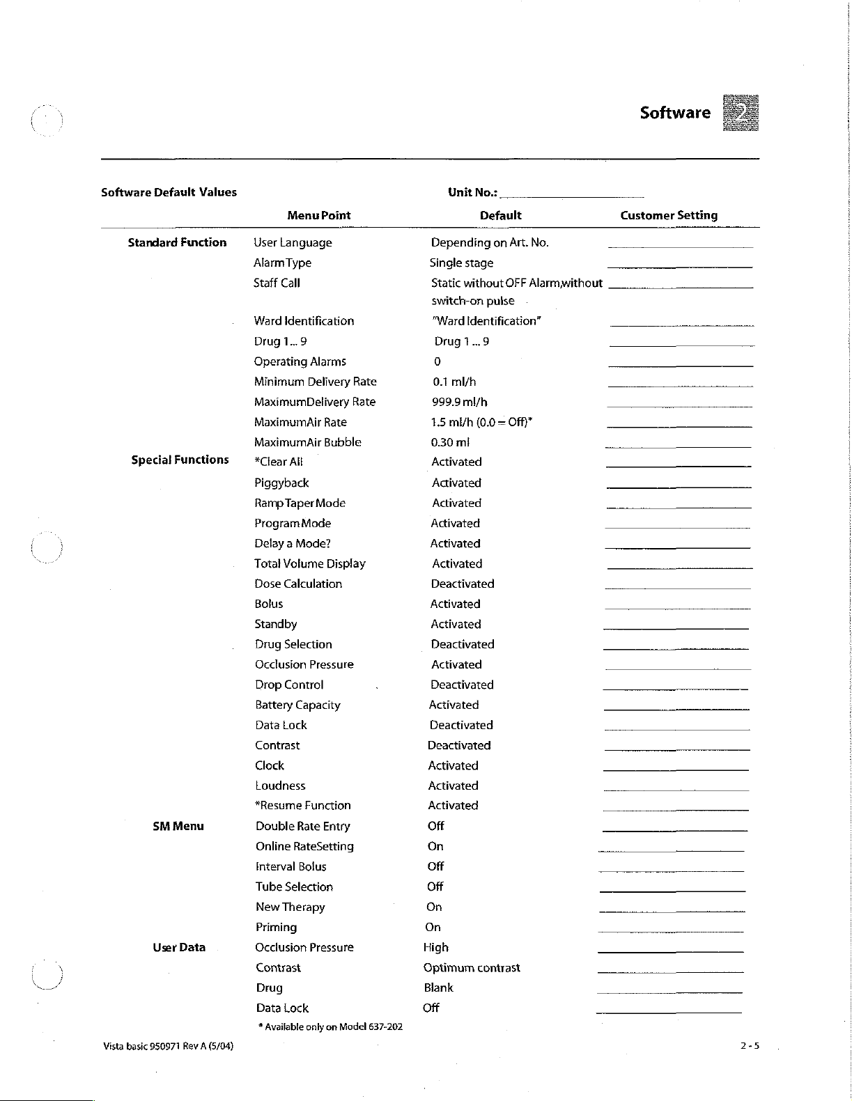
Software
Software
Standard
Special
Vista
basic
Default
Functions
SM
Menu
User
950971
Values
Finction
Data
Rev A (5/04)
Menu
Point
User
Language
AlarmType
Staff
Call
Ward
Identification
Drug
1..9
Operating
Minimum
MaximumDelivery
MaximumAir
MaximumAir
*Clear
Alarms
Delivery
Rate
Bubble
All
Piggyback
Ramp
Taper
Mode
Program
Mode
Delay a Mode?
Total
Dose
Bolus
Volume
Calculation
Display
Standby
Drug
Selection
Occlusion
Drop
Battery
Data
Contrast
Pressure
Control
Capacity
Lock
Clock
Loudness
*Resume
Double
Online
Interval
Tube
New
Priming
Occlusion
Contrast
Drug
Data
*
Rate
RateSetting
Bolus
Selection
Therapy
Lock
Available
Function
Entry
Pressure
only on
Rate
Rate
Model
637-202
Unit
Depending
Single
stage
Static
without
switch-on
"Ward
Identification”
Drug
1...9
0
0.1
ml/h
999.9
ml/h
1.5
mi/h
0.30
ml
Activated
Activated
Activated
Activated
Activated
Activated
Deactivated
Activated
Activated
Deactivated
Activated
Deactivated
Activated
Deactivated
Deactivated
Activated
Activated
Activated
Off
On
Off
Off
On
On
High
Optimum
Blank
Off
No.:
Default
on
Art.
OFF
Alarmwithout
pulse
(0.0 = Off)"
contrast
No.
Customer
Setting
Page 26

Software
Calibration
Unit
Specific
Data
Data
Standby
Drop
Control
Alarm
Tone
Dianet
Mode
Bolus Key
Bolus
Rate
Air
Sensor
Tube
group!
(dependent
Air
Sensor
Intrafix
(dependent
Scale
Factor
(dependent
Occlusion
Occlusion
History
Function
DIANET
Type
No.
Unit
Operating
Battery
Hours
Number
Menu
Point
Time
Display
Calibration
on
Calibration
Air P or
Vista
on
on
tube)
Level,
Low
Level,
High
No.
Hours
of
Pump
Head
Value
tube)
tube}
Value
Pump
Cycles
Set
24h
00min
Off
Stage
7
60sec
On
999.9
mi/h
130
mV
130
mV
50
(Intrafix
6
(no
PSI)
12
(no
PSi)
Activated
Depending
Depending
Depending
Depending
Depending
Default
Air P or
on
unit
on
unit
on
unit
on
unit
on
unit
Vista
Pump
Set)
Must
Must
Customer
not
be
changed
not
be
changed
Setting
Vista
basic
950971
<
Rev A (5/04)
Page 27

Service
Program
Structure
Standard
of
(see
operating
flow
diagram}
the
Service
Operation
Program
Group:
Unit
Software
Ward
Tube
Serial
DIANET
Data
Version
100.0
Drug
110.0
identification
120.0
Type
130.0
Number
140.0
Type
No.
150.0
Group:
History
Operating
Battery
Pump
Alarms
Service
Tube
New
Prime
Data
200.0
Op.
210.0
Head
Cycles
220.0
230.0
Plug,
Inserted
Type
Selection
Therapy
Set?
Hours
Hours
Special
(see
flow
Service
Activated
|
Occlusion
Temperature
Functions
operating
diagram)
Program
Group:
Test
Air
Sensor
300.0
310.0
320.0
Sensor
Sensor
Unit
É
Е
Service
Special
Group:
Modification
Language
400.0
User
Language
410.0
Alarm
Tone
420.0
Staff
Call
430.0
Function
440.0
Menu
450.0
Delivery
Rate
460.0
Air
Alarm
470.0
È
Calibration
Occlusion
500.0
Scale
Factor
5100
Air
Sensor
520.0
Occlusion
540.0
Pump
Data
550.0
History
560.0
Sensor
Level
Vista
basic
950971
Rev A (5/04)
Dianet
Display
480
Priming
490.0
Mode
Volume
Page 28
Service
Program
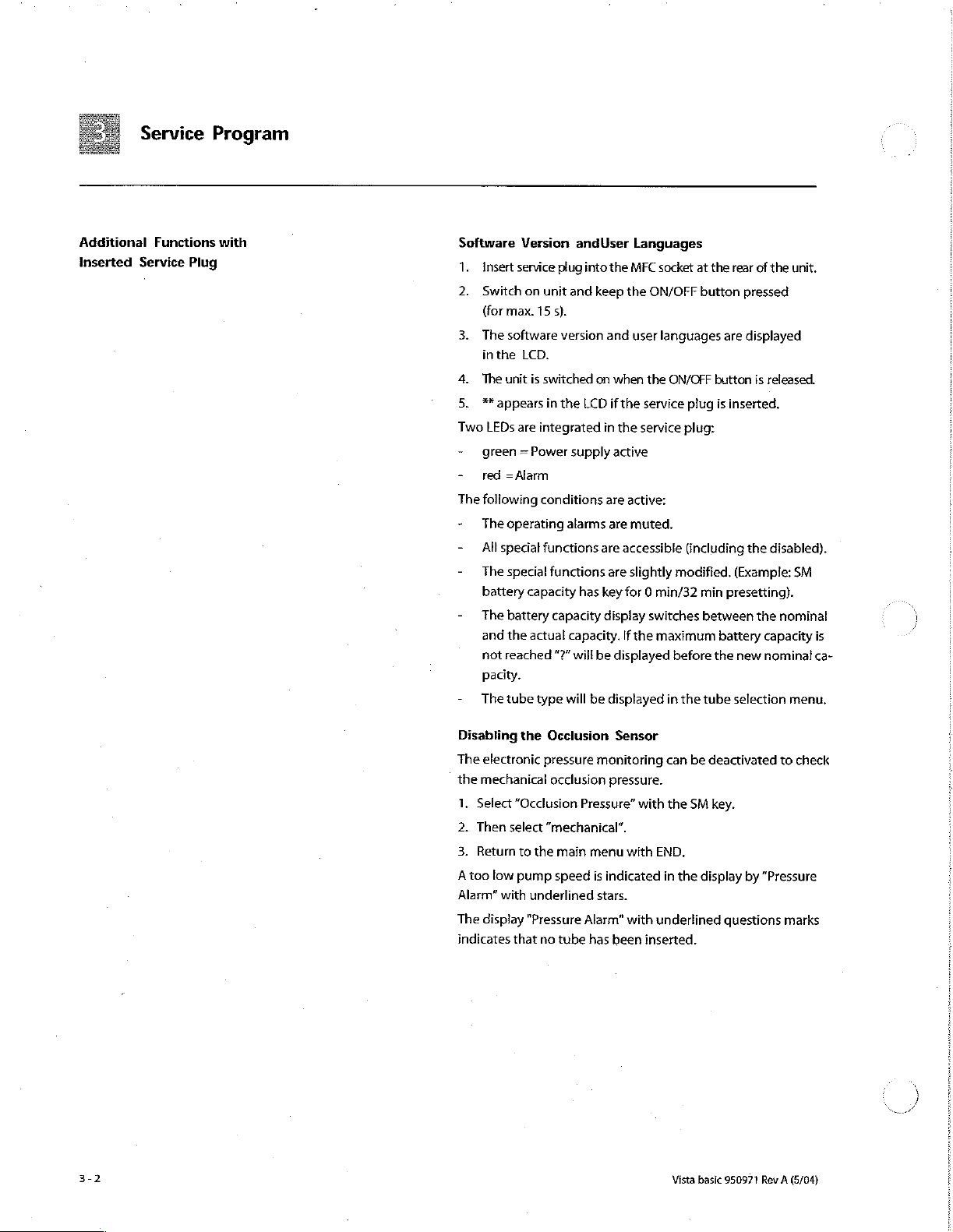
Additional
inserted
Functions
Service
Plug
with
Software
1.
Insert
2.
Switch
(for
max.
3.
The
software
inthe
4.
The
unit
5.
**
appears
Two
LEDs
-
green = Power
-
red
=Alarm
The
following
-
The
operating
-
All
special
-
The
special
battery
-
The
battery
and
the
not
reached
pacity.
-
The
tube
Version
service
plug
on
unit
15
s).
version
LCD.
is
switched
in
the
are
integrated
conditions
functions
functions
capacity
capacity
actual
”?”
type
andUser
into
the
and
keep
and
on
when
LCD
if
in
supply
active
are
alarms
are
are
are
has
key
display
capacity.
will
be
displayed
will
be
displayed
Languages
MFC
socket
the
ON/OFF
user
languages
the
ON/OFF
the
service plug
the
service
active:
muted.
accessible
slightly
for 0 min/32
If
switches
the
maximum
in
modified.
before
at
the
rear
button
are
button
is
inserted,
plug:
(including
(Example:
min
presetting).
between
battery
the
new
the
tube
selection
of
the
unit.
pressed
displayed
is
released.
the
disabled).
the
nominal
capacity
nominal
menu.
SM
is
ca-
i
)
i
Disabling
The
electronic
the
mechanical
1.
Select
2.
Then
select
3.
Return
A
too
low
Alarm”
with
The
display
indicates
the
Occlusion
pressure
occlusion
“Occlusion
“mechanical”.
to
the
main
pump
speed
underlined
"Pressure
that
no
tube
Sensor
monitoring
pressure.
Pressure”
menu
Alarm”
has
with
with
is
indicated
stars.
with
been
can
be
the
SM
END.
in
the
display
underlined
inserted.
Vista
basic
deactivated
key.
by
"Pressure
questions
950971
Rev A (5/04)
to
check
marks
Page 29

Service
Program
Start
/Quit
the
Service
Fig:
3-2
i
ο
Fig:
3-
à
3
Program
πες
à à à
Activate
1.
2.
12007
FUNCTION
:
FE
16008
the
Insert
service
- * appears
Select
"Service
program
plays
END
GR+
FU+
OK
is
the
code
Jumps
Selects
Selects
activated
Activates
necessary
with
Service
plug
into
in
the
display.
Program”
activated
number
to
group
function
대
NEXT
Program
the
MFC
with
the
red
of
the
the
initial
group
the
selected
skips
to
socket
the
SM
alarm
LED
selected
function
in
the
function
the
sub-functions
at
the
key.
When
flashes.
group
or
Quit
the
1.
2.
Press
END
vated:
Y/N
terminates
Press
Switch
Service
END
in
the
“Save
Changes?
to
jump
off
the
Infusomat P and
Program
main
menu - À
the
service
to
the
data
Yes / No”.
program.
last
function.
remove
storage
service
rear
of
the
the
service
The
LED
and
function.
if
query
is
acti-
plug.
unit.
dis-
Unit
Vista
Data
basic
950971
Rev A (5/04)
Disconnect
ter
termination
the
unit
Software
1.
2.
3.
can
Select
The
current
-
User
-
Language
-
Service
-
Service
-
Tube
Return
the
Vista
basic
of
the
service
be
switched
Version
sub-functions
software
program
type
to
version
with
text
program
language
version
the
initial
version
with
function
from
mains
for
at
least
program
on
again.
with
version
with
version..Further
text
NEXT.
is
date
version
with
(memory
displayed
languages
END.
30
seconds
is
deleted).
Function
in
the
LCD:
with
af-
Then
100.6
(+).
3-3
Page 30

Service
Program
Drug
Name
Memory
1.
2.
3.
4.
Ward
Enter
display
1.
2.
3.
009
for
maximum 9 drugs
Display
the
stored
Delete
displayed
Press
YES
to
modify a drug
Move
cursor
to
Select
new
character
Repeat
the
procedure
Return
to
the
Identification
and
display
of a ward
if
the
unit
is
Delete
displayed
ifications:
Move
cursor
to
Select
new
character
Repeat
the
procedure
Return
to
the
drug
names
entry with CLR.
character
from
for
initial
function
specific
connected
entry
with
character
from
for
initial
function
and
20
with
name:
with
NEXT.
line 3 with
each
character.
with
unit
identification.
to
mains
CLR.
Press
with
NEXT.
line 3 with <<
each
character.
with
Function
characters
the
NEXT
<<
or
END.
Function
and
switched
YES
to
or
END.
110.0
per
name.
key.
>>.
120.0
Permanent
off.
enter
mod-
>>.
Tube
This
function
Serial
The
displayed
the
unit
1.
YES
2.
YES
3.
Return
DIANET
The
displayed
the
unit
1.
YES
2.
YES
3.
Return
Type
Number
type
activates
stores
to
Type
type
activates
stores
to
is
for
serial
plate,
the
the
the
initial
Number
serial
plate,
the
the
the
initial
future
number
as
this
entry
changed
function
number
as
this
entry
changed
function
extensions.
must
correspond
number
number
mode.
or
new
must
mode.
or
new
is
used
Enter
number.
with
correspond
is
used
Enter
number.
with
in
via
END.
in
via
END.
with
the
the
Function
with
the
the
Function
Function
the
number
interface
numeric
the
number
interface
numeric
130.0
140.0
on
mode.
keypad.
150.0
on
mode.
keypad.
Vista
basic
950971
Rev A (5/04)
Page 31

Service
Program
History
Data
Operating
1.
2.
Battery
1.
2.
Pump
Display
1.
2.
Operating
The
They
be
1.
set
PEN
Hour
OK
activates
Return
Operating
OK
activates
Return
Head
of
OK
activates
Return
last
20
aredisplayedas
from 0 to
OK
activates
Display
Delete
Return
the
to
the
the
to
the
Cycles
the
pump
the
to
the
Alarms
operating
1.
the
operating
the
operating
to
the
Counter
display.
initial
function
Hours
display.
initial
function
head
display.
initial
function
alarms
16
bit
alarm
alarms
initial
function
cycles
can
binary
codes
display.
-01 to
alarms
with
END.
with
END.
(delivered
with
be
with
with
volume).
END.
recalled.
andeach
-20
with
CLR.
END.
Function
Function
Function
Function
bit
positioncan
the
(+)
and
200.0
210.0
220.0
230.0
(-)
key.
Vista
basic
950971
Rev A (5/04)
Page 32

Service
Program
Test
.
Air
Sensor
After
exchange
See
TSI-List
inspection
1.
Press
measurement
(The
test
2.
Insert
permissible
3.
Insert
minimum
4.
Return
Pressure
Test
Eguipment
2.2
mm
template
{see
“Test
Push
Press
ウー
Open
の
Note
お
Insert
pu
The
new
be
15
7.
Return
If
the
15
to
must
be
pg.
4-14}.
check
for
permissible
TSF
pg.
72-15.
OK.
The
received
value,
value
with
an
infusion
air
value.
an
infusion
permissible
to
the
initial
Sensor
Eguinmentand
in
the
bottom
OK
twice.
unit
door.
the
measurement
the
2.2
mm
measurement
to
25
digits
to
the
initial
25
digits
mechanically
the
function
signal
NEXT
line
filled
line
filled
water
function
slide
template
higher
function
are
not
aligned
of
the
air
check
values
(see
amplitude
is
not
with
with
value.
with
Special
of
the
value
and
value
than
with
reached,
is
displayed
important).
air
and
check
fluid
and
END.
Tools”
finger
pump.
(actual
value).
close
the
will
be
displayed.
the
first
value.
END.
the
pressure
isee"OcclusionSensor“
Function
sensor.
schnical
as
the
maximum
check
the
Function
po.
9-1)
unit
door.
It
sensor
300.0
Safety
a
310.0
must
unit
:
İ
|
3-6
Temperature
Display
of
the
tions
are
possible,
1.
OK
activates
2.
Return
to
Sensor
measured
the
the
display.
the
initial
temperature
display
is
function
only
with
of
both
for
internal
END.
Vista
basic
Function
processors.
use.
950971
Rev
320.0
Devia-
A
(5/04)
Page 33

Unit
Modifications
Service
English
1.
2.
3.
4
User
Four
(depending
1.
2.
4.
Language
or
OK
activates
Select
Acknowledge
Return
Language
user
OK
activates
Select
The
language
Acknowledge
Return
German
the
language
with
to
the
initial
languages
on
software).
the
language
no.
with
to
the
initial
Service
can
be
function.
with
YES.
function
per
language
function.
with
and
YES.
function
selected.
NEXT.
with
NEXT.
text
version
with
Program
END,
group
are
are
END.
Function
Function
available
displayed.
400.0
410.0
Alarm
Tone
Different
-
-
The
-
- © the
1.
PEN
alarm
Single
A"10
minutes
In
this
mode
of
10minutes.
activation
the
staff
Vista
M007100000F04).
OK
activates
Select
Acknowledge
Return
stage
of
call
basic
alarm
to
the
modes
off
the
audible
the
10
is
connected
has
the
tone
with
initial
can
be
selected:
alarm”
can
alarm
minutes
and
an
attention
function.
with
NEXT.
YES.
function
be
off
with
is
alarm
Function
selected.
activated
is
only
label
(label
END.
420.0
with a delay
permissible,
drawing
no.
if:
Vista
basic
950971
Rev A (5/04)
3-7
Page 34

3
|
Service
UNIT
OFF
Optical?
Alarm
Alarm
ON
FERE
Alarm
DEF:
+ に i
AudibleO
Alarm
‘ures
Alarm
Fig:
on
SESE
OFF.
3-6
a
и
Program
UNIT
ON
Operating
Alarm
Off
Alarm,
Staff
Cal!
Select
first,
whether
NO).
The
switch-on
ferent
staff
„UNIT
OFF
Zinet
“START
ade
oo
-
-
-
For
An
additional
mode
1.
2.
3.
4.
call
Dynamic
Dynamic
Static
without
further
details
to
test
OKactivates
Select
staff
Acknowledge
Return
to
the
pulse
modes
with
OFF
without
OFF
see
switch-on
the
staff
the
function.
call
type
with
the
initial
switch-on
is
used
can
be
Alarm
OFF
Alarm
Alarm
staff
call
pulse
(YES/NO)
call
unit.
with
NEXT.
YES.
function
pulse
to
test
selected
line
in
with
END.
Function 430.0
shall
be
the
staff
with
the
the
instructions
can
be
activated
activated
call
NEXT
line.
key:
for
for
(YES/
Dif-
each
use.
Special
Special
are
tions
in
Special
Functions
functions
then
available
will
not
standard
functions
can
be
on
the
be
displayed.
operation,
to
be
activated
user
interface.
The
SM
if
all
special
selected,
in
the
Deactivated
softkey
functions
see
Fig:
service
will
not
are
1-4.
Function
program,
440.0
which
special
func-
be
displayed
deactivated.
-
1.
OK
activates
Select
special
Activate / deactivate
た の »
Return
to
the
the
function.
functions
the
main
menu
with
NEXT.
respective
with
END.
Vista
function
basic
950971
with
YES/NO,
Rev A (5/04)
Se
Page 35

Service
Program
Menu
The
availability
-
Double
-
Online
-
Interval
-
Tube
1.
OK
2.
Activate / deactivate
3.
Acknowledge
4
Return
Delivery
The
maximum
of
adjustment
1.
OK
Select
Acknowledge
Enter
SSN
Acknowledge
Return
Ou
of
rate
entry
rate
entry
bolus
selection
activates
to
the
Rate
and
of
activates
the
the
min./max.
value
with a numeric
to
the
menus
the
function.
with
YES.
main
menu
minimum
the
delivery
function.
with
YES.
with OK.
initial
on
the
the
decimal
with
delivery
rate:
delivery
key.
function
user
interface
function
END.
0.1
rate
with
rates
to
999.9
with
END.
Function
can
be
with
Function
can
be
set.
ml/h
NEXT.
450.0
set.
NEXT.
460.0
Range
Vista
basic
950971
Rev A (5/04)
Air
Alarm
The
air
sensor
air
alarm)
ble}
can
Setting
range
Setting
range
1.
OK
activates
본
Select
Acknowledge
の
まお
Enter
Acknowledge
の の
Return
and
be
adjusted.
air
value
to
sensitivity
of
air
air
rate
the
of
the
the
maximum
rate:
0.5
to
3.5
bubble:
the
0.01
function.
(mi/h)
or
with
YES.
air
with a numeric
with OK.
initial
function
air
air
bubble
ml/h
to
0.3
bubble
key.
with
rate
ml/h
(ml)
END.
Function
alarm
in
ml
with
in
ml/h
(single
NEXT.
470.0
{total
bub-
Page 36
Service
Program
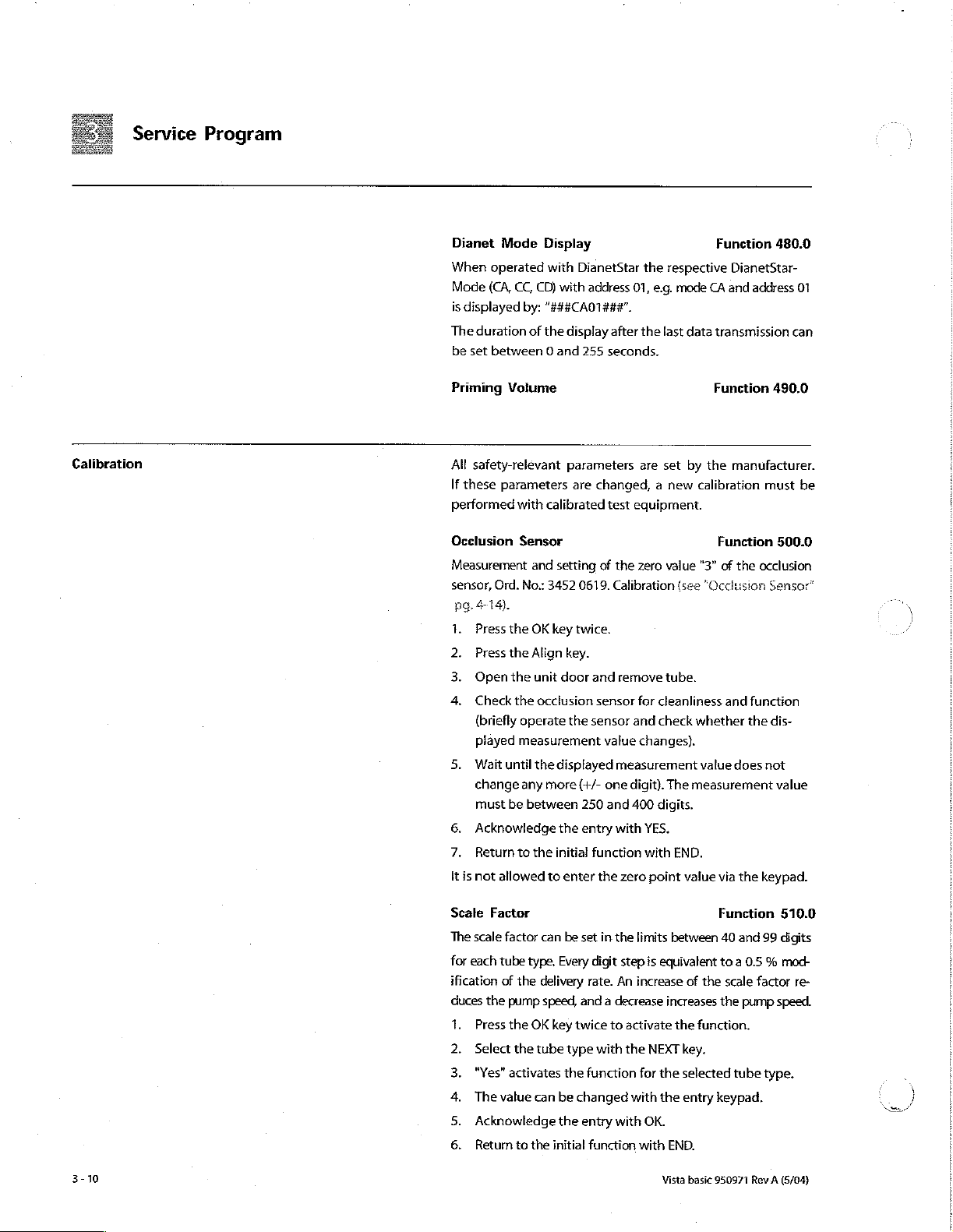
Calibration
Dianet
When
Mode
is
The
be
Priming
All
If
performed
Occlusion
Measurement
sensor,
pg.
1.
2.
3.
4,
5.
6.
7.
It
Mode
operated
(CA,
CC,
displayed
duration
set
safety-relevant
these
414).
Press
Press
Open
Check
(briefly
played
Wait
change
must
Acknowledge
Return
is
not
by:
between 0 and
Volume
parameters
with
Sensor
Ord.
No.:
the
the
the
the
operate
measurement
until
any
be
to
allowed
Display
with
DianetStar
CD)
with
“###CA01###".
of
the
display
255
parameters
are
calibrated
and
setting
3452
0619.
OK
key
twice.
Align
key.
unit
door
occlusion
the
the
displayed
more
(+/-
between
the
250
the
entry with
initial
to
enter
the
address
01,
e.g.
after
the
last
seconds.
are
set
changed, a new
test
equipment.
of
the
zero
Calibration
and
remove
sensor
for
cleanliness and
sensor
and
check
value
changes).
measurement
one
digit).
and 400
function
the
zero
digits.
YES.
with
point
Function
respective
mode
CA and
data
transmission
Function
by
the
calibration
Function
value
"3"
(see
“Occlusion
tube.
whether
value
The
measurement
END.
value
via
480.0
DianetStar-
address
can
490.0
manufacturer.
must
500.0
of
the
occlusion
Sansor*
function
the
dis-
does
not
value
the
keypad.
01
be
A
/
3-10
Scale
Factor
The
scale
factor
for
each
tube
ification
duces
1
2
3
4.
5.
6.
of
the
Press
Select
"Yes"
The
value
Acknowledge
Return
can
be
type.
Every
the
delivery
pump
speed,
the
OK
key
the
tube
activates
to
can
the
the
be
the
initial
set
in
the
digit
step
rate.
An
and a decrease
twice
to
activate
type
with
the
function
changed
entry with
with
function
limits
between
is
equivalent
increase
for
with END.
increases
NEXT
the
the
OK.
Vista
of
the
key.
selected
entry
Function
40
and
to a 0.5 % mod-
the
scale
the
function.
tube
keypad.
basic
950971
510.0
99
digits
factor
pump
speed.
type.
Rev A (5/04)
re-
Page 37

Service
7.
Quit
the
service
8.
Switch
curacy”
KH
necessary
Air
Sensor
Alignment
{see
“Air
“Not
The
value
Press
>
Press
WN
The
value
Acknowledge
ES
M
AIR
SENSOR
Return
NPD
Quit
onunit
pg.
or
check
Sensor”
is
dependent
OK
twice
OK
again
can
to
the
the
service
program
and
8-4},
repeat
of
pg.
4-17).
and
to
be
changed
the
IS
SET
initial
program
and
check
the
delivery
the
delivery
the
air
sensor
on
the
then
YES
activate
entry
the
with
acknowledges
function
and
save
rate
tube
to
air
with
YES.
with
save
activate
the
Program
changes
rate
(see
measurement.
Function
value
(alarm
type.
the
sensor
value.
entry
keypad.
the
entry.
END.
changes
with
YES.
“Delivery
Ac-
520.0
threshold)
function.
with
YES.
Occlusion
Setting
of
the
levels
"low"
Press
the
Select
the
YES
activates
PWN
Enter
the
attention
Y
Press
the
Return
to
Pump
Data
Compatibility
be
checked
pump
corresponds
History
The
history
1.
Press the
2.
Select
the
Level
occlusion
and
"high".
OK
key
occlusion
the
pressure
to
the
YES
key
the
initial
between
before
to
function
OK
key
history
threshold
twice
level
entry
value
displayed
to
take
function
controller
to
activate
with
mode.
via
limit
over
values
NEXT.
the
values!).
the
with
acknowledging.
controller
can
be
twice
function
board.
activated
to
activate
with
Function
for
the
the
function.
numeric
keys
settings.
END.
Function
board
and
Only
press
Function
or
deactivated.
the
function.
NEXT,
540.0
occlusion
(pay
550.0
pump
must
YES
if
560.0
Vista
basic
950971
Rev A (5/04)
Page 38

Service
Program
ON
activates
initialized
number
Press
protocol
Return
the
to
(the
are
OFF
memory
the
the
function.
actual
software
registered).
key
to
deactivate
is
deleted.
initial
function
The
with
history
protocol
version
the
function.
END.
and
the
The
memory
serial
history
is
Vista
basic
950971
Rev A (5/04)
Page 39

Unit
Elements
41
Mains
4.2
Battery
Fig:
4-1
Fuses
Designation
Fuse T 0.315 A for
(10
рс$.)
.......-
Fuse
holder.
......,..,.,.................,....
“Note;
Only
use
recommended
Exchange
1.
Presstheexpansion
recessed
the
arrows
2.
Replaceblownfuseandpress
recommended
Check
Safety
check,
Designation
Battery
incl.
connector
Exchange
1.
Switch
off
2.
Loosenscrew,
and
remove
Pull
off
the
4.
Assembly
After
having
be
connected
Thereby
6.
Charge
battery
100/110/120V
mains
plug
and
pull
fuses.
functional
unit
and
open
battery.
battery
is
done
exchanged
to
mains,
the
charge
(16
fuses.
damps
at
with a screw
out
fuse
check.
1.2
AH
/7.2 V and
disconnect
the
cover
connector.
in
reverse
the
before
and
discharge
h).
the
fuse
driver
holder.
in
fuse
from
of
the
order.
battery
switching
currents
ke
holder
in
direction
holder.
holder.
mains.
battery
the
Vista
on
Ord.
No.
3477
0534
3450 0979
on
the
of
Only
use
Ord.
No.
...
3450
2556
compartment
basic
must
the
unit.
are
aligned.
Vista
basic
950971
Rev A (5/04)
Defective
back
to
Perform
battery
B.
switch-on
running
Check
batteries
Braun
must
(see
test
time,
be
orderly
"Return
in
battery
if
necessary.
disposed
of
Spare
operation
of,
Parts”
and
e.g.
pg.
0-7).
check
send
the
Page 40
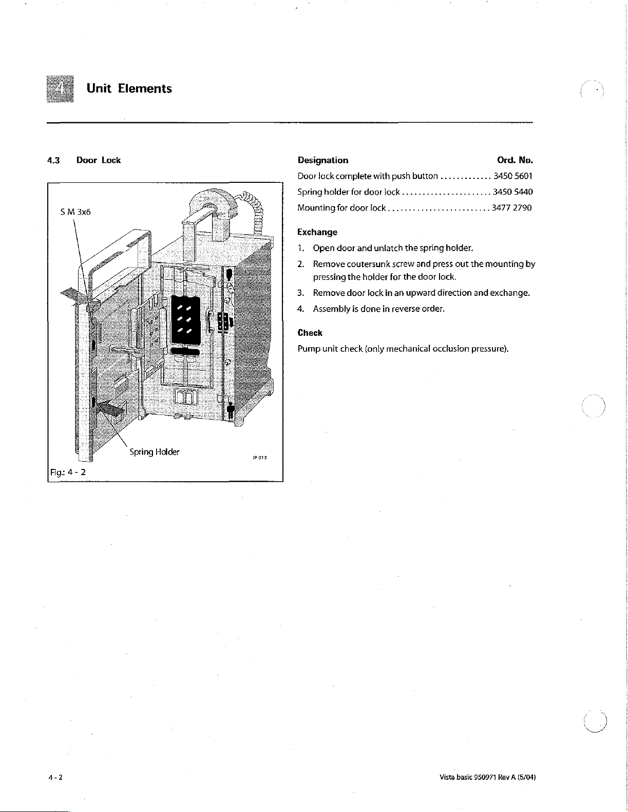
Unit
Elements
43 Door
Lock
Spring
Holder
Designation
Door
lock
complete
Spring
holder
Mounting
Exchange
1.
2.
4.
Check
Pump
for
Open
door
Remove
pressing
Remove
Assembly
unit
check
with
push
button
for
door
lock.
door
lock.........................
and
unlatch
the
spring
coutersunk
the
door
is
done
holder
lock
in
in
(only
mechanical
screw
for
the
an
upward
reverse
and
press
door
order.
occlusion
direction
.............
...
3450 5440
3477 2790
holder.
out
the
mounting
lock.
and
exchange.
pressure).
Ord.
3450
No.
5601
by
Fig:
4-2
Vista
basic
950971
Rev A (5/04)
Page 41

4.4
Pump
Blind
Hinge
Purnp
PI
Cover
Pin
for
Cover
Unit
Designation
Pumpcoverwithlock..........................
Blind
plug
7.1
mm
(10
pcs.)
......:........,....,
Torsion
spring
in
Torsion
spring
Lever
(pump
Hinge
pin
Hinge
pin
Exchange
Tools:
Pin
1.
Open
from
2.
Disassemble
3.
Insert
pin
from
4.
Check
vice
lever/pump
for
pump
cover).
for
pump
for
pump
punch
door
and
below.
Do
pump
the
torsion
the
top with a pin
the
occlusion
program,
.......................,....
cover
cover
1.8
and
cover
.........
lever.
mm,
remove
not
lose
cover.
spring
sensor
align,
cover
pin
hinge
in
Elements
(5
pcs}
........
(5
pcs.)
............
..................
punch 6 mm,
the
new
punch
with
if
necessary.
.... . 3477 3967
pin
with
pin
torsion
spring.
pump
cover.
(6
mm).
2.2
mm
3477
3477 3355
3477
3450
2.2
mm
punch
Insert
template
Ord.
No.
3450
1916
3477
3207
3363
4092
5725
template
(1.8
mm)
the
hinge
in
the
ser-
ーー
Hinge
Pump
Fig:
4-3
Pump
Cover
Pin
for mora
Cover
Lever
Torsion
Spring
Check
Safety check,
pump
unit
check.
Vista
basic
950971
Rev A (5/04)
Page 42
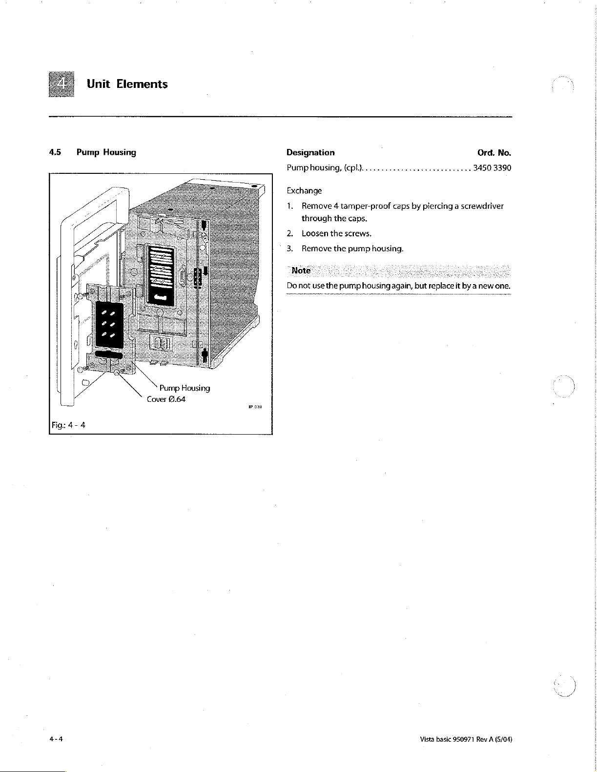
4.5
Unit
Pump
Elements
Housing
Designation
Pump
housing,
Exchange
1.
Remove 4 tamper-proof
through
2.
Loosen
3.
Remove
(cpt.}..............,..,,,..,..,,,
the
the
screws.
the
caps.
pump
caps
housing.
3450
by
piercing a screwdriver
Ord.
No.
3390
Note.
Do
not
use
the
pump
housing
again,
but
replace
it
by a new
one,
Pump
Fig:
4-4
Cover
2.64
Housing
1P
038
Vista
basic
950971
一
~
Rev A (5/04)
Page 43

3
Unit
4.6
Housing
PT5.0x16
È
and
Handie
Power
fixation
|
[
|
會
|
cord
Designation
Housing
Foot
Rubber
Unit
Power
Exchange
1.
2
3.
4
5.
6.
Check
Safety
Labelling
stand
feet
handle
cord
Remove
Loosen 4 screws
Remove
Remove
roof
cap
P p
Slidiy
widen
pull
off
Lay the
Safety
check.
............,.......,.,......
complete
(20
with
fixation
to
unit
seal
with
rubber
pes]
.........,,.......,........
O-rings
and
PT
...........,......,..,......
battery
(see
"Battery"
from
the foot
the
plug
holder.
the
safety
seal
from
and
the
the
on
the
remove
top.
sides
the
rear
screw.
at
front
panel
the
side
feet
screws
pg.
stands
the
bottom
and
screw
rear
Elements
Ord.
3452 0643
.............
........... 3450 3450
4-1).
and
panel,
of
assemble
after
functional
remove
break
the
housing
in
3450
3477 3096
3452
foot
stands.
tamper-
and
reverse
order.
check.
5415
0651
No.
Fig:
4-5
Vista
basic
950971
Rev A (5/04)
8
OK
4x
M4x8
8
06015
4-5
Page 44

Unit
4.7
Controller
Cable
Output
Flex
Cable
Fig:
4-
6
Press
Elements
Board
Motor
LCD
snap-in
Air
Module
pin
Prin
pin tog
Sensor
Motor
Reed
Sensoi
Connector
Loudspeaker
together
Connector
Connector
Occlusion
Connector
Battery
tor
Sensor
Rear
Panel
Connector
wate
Connec-
Designation
Distancesleeve
loudspeaker..................................
Controller
volume
raw
material
Exchange
1.
Remove
2.
Dismount
3.
Press
the
board
4.
Pull
off
Exchange
6.
Assembly
optical
parallel
optical
if
"Calibration
the
controller
up)
was
assembled.
...............................
board
with
loudspeaker,
control
and
history
function,
no.
battery
housing
snap-in
pin
carefully.
connector
the
board
is
done
components.
to
the
interface
Defective’
board,
3810 8003
(see
together
(see
in
base
can
check
...........,.....
“Battery”
(see
"Housing
at
the
figure).
or
buzzer.
reverse
order.
Insert
the
plate.
(Otherwise
occur.)
is
displayed
that
the
pg.
and
distance
Be
board
after
correct
4-1).
Handia”
sleeves
careful
into
problems
having
board
Ord.
3450
3450 8848
3450 8740
and
with
the
lower
exchanged
(risk
pg.
4-5).
remove
the
with
of
No.
3366
guide
the
mix-
4-6
Check
Safety check,
functional
check.
Vista
basic
950971
À
Rev A (5/04)
Page 45
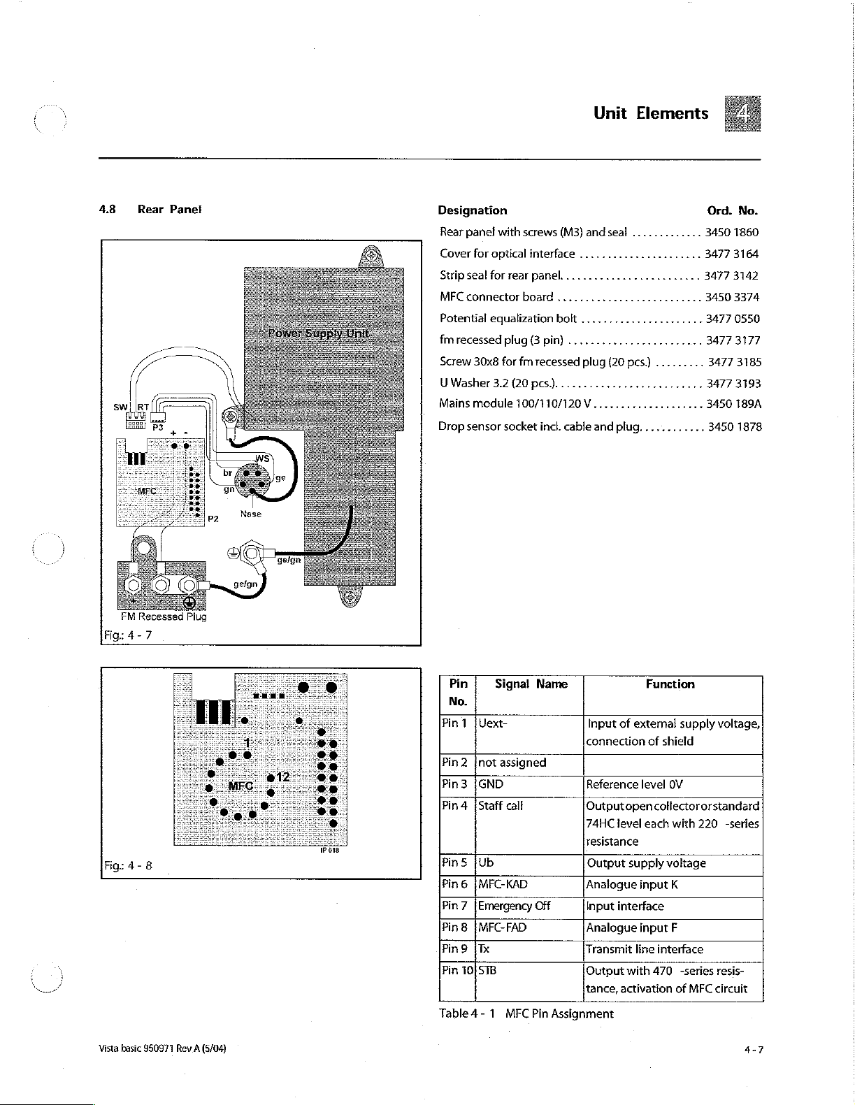
4.8
Rear
Panel
Unit
Designation
Rear
panel
with
screws
(M3)
and
Cover
for
optical
interface
Stripsealforrearpanel.........................
MFCconnectorboard..........................
Potential
fm
Screw
UWasher3.2(20pcs)..........................
Mains
Drop
equalization
recessed
30x8
module
sensor
plug
(3
for
fm
recessed
100/110/120
socket
......................
bolt
......................
pin)
........................
plug
V. .. + 3450 189A
incl.
cable
and
seal
.............
(20
pcs.)
plug...
Elements
.........
Ord.
3450
1860
3477 3164
3477
3142
3450 3374
3477
0550
3477
3177
3477 3185
34773193
..
3450
No.
1878
OO
FM
Fig:
4-7
Fig:
4-
Recessed
8
(O
Plug
018
Pin
No.
Pin 1 }Uext-
Pin 2 ¡not
Pin3
Pin 4 {Staff
Pins
Pin 6 IMFC-KAD
Pin 7 |
Pin8
Pin9
Pin
Table 4 - 1 MFC
Signal
assigned
{GND
call
¡Ub
Emergency
IMFC-FAD
(Tx
10/STB
Name
Off
Pin
Assignment
Function
Input
of
external
connection
Reference
Outputopen
74HC
resistance
Output
Analogue
Input
Analogue
Transmit
Output
tance,
of
level
level
each
supply
input
interface
input
line
with
470
activation
supply
shield
OV
collector
or
with
220
voltage
K
F
interface
-series
of
MFC
voltage,
standard
-series
resis-
circuit
Vista basic
950971
Rev A (5/04)
Page 46
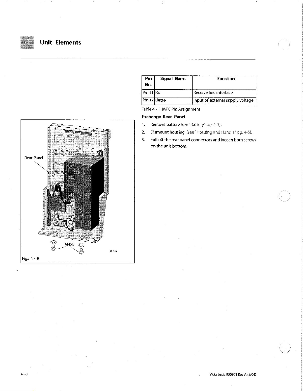
Rear
Unit
Panel
Elements
Pin | Signal
No.
Pin
TI
İRx
Pin
12}
Uext+
Table 4 - 1 MFC
Exchange
1.
Remove
2.
Dismount
3.
Pull
off
on
the
Pin
Rear
battery
housing
the
rear
unit
bottom.
Name
Assignment
Panel
(see
(see
panel
Receive
Input
“Battery”
“Housing
connectors
line
of
external
pg.
4-1).
and
and
Function
interface
supply
Handle”
loosen
voltage
pg, 4-5).
both
screws
Fig:
4-9
©
8
x!
—
$
Pois
Vista
basic
950971
Rev A (5/04)
Page 47
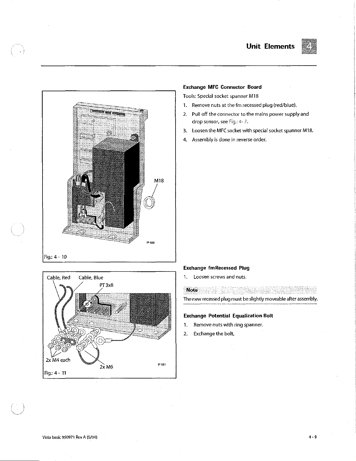
Unit
Elements
Mi8
Exchange
Tools:
1.
2.
3.
4.
MFC
Special
Remove
Pull
off
drop
sensor,
Loosen
Assembly
Connector
socket
nuts
the
connector
see
the
MFC
is
done
spanner
at
the
Fig.:
socket
fm
4-7.
in
reverse
Board
M18
recessed
to
the
mains
with
special
order.
plug
(red/blue).
power
socket
supply
spanner
and
M18.
1P
020
Fig:
4-
10
Cable,
Red
©
©
2x
M4
each
Fig:
4-
11
Cable,
©
Blue
PT
2x
3x8
M6
Exchange
1.
The
Exchange
1.
2.
IP
021
Loosen
new
recessed
Remove
Exchange
fmRecessed
screws
and
plug
Potential
nuts with
the
bolt.
Plug
nuts.
must
Equalization
ring
be
slightly
spanner.
moveable
Bolt
after
assembly.
Vista
basic
950971
Rev
(5/04)
A
4-9
Page 48

Unit
Elements
Power
Supply
Unit
Fig: 4 -
4.9
12
Front Panel
De
M3x10
Snap-In
(Rear
Pin
Side)
Exchange
Tools:
1.
Note.
The
fuse
Exchange
1.
2.
3.
Check
Safety check,
Designation
Front
Circularseal45
Tamper-proof
Cover
Clamp
Torsion
Reedsensor...................................
Mains
Module
Screw
driver
Loosen 3 screws
voltage
selection
element.
Drop
Loosen
Safety
lock
Make
ground
panel
without
964
lever
with
spring
Sensor
nut
and
with
functional
mm............................
caps
torsion
.............,..................
Torx
T10
and
remove
for
switchable
Socket
exchange
Sicomet
connection.
check.
clamp
lever
10
mm
(50
spring
the
power
supply
È
power
supplies
the
drop
sensor
socket.
50.
and
torsion spring. . 3450 2092
pcs.)
and
pin
4x20
......
..
..
unit.
is
at
the
Ord.
No.
3477
3126
3477
3134
3450
3412
3450 3420
3450
3439
3450
1754
、
/
Tamper-Proof
때
ig:
4-
4-10
13
Cap
(10mm)
Reed
(Rear
Snap-in
(Rear
Side)
Sensor
Side)
Pin
023
Exchange
Tools:
Pin
1.
Remove
2.
Dismount
3.
Disassemble
4.
Disassemble
pg.
4-4).
5.
Remove
through
6.
Press
Fig:
7.
Press
Then
8.
Exchange
screw.
surfaces
punch
battery
housing
countersunk
the
caps
reed
sensor
4-14.
both
snap-in
remove
the
Prior
to
with
(ses
{see
pump
pump
to
out
pins
the
front
flow
inhibitor,
assembly
Molikote
“Battery”
“Housing
cover
{see
housing
screws
foosen
of
the
inwards
panel
slightly
Platislip
pg.
4-1).
and
Handle”
"Pump
Cover”
(see
“Pump
Housing”
by
piercing a screwdriver
the
countersunk
holder
on
the
rear
(rear
side
top
and
to
the
front.
i.e,
pull
straight
grease
the
plastic
PG
602
grease.
Vista
basic
950971
pg.
4-5).
pg.
4-3).
screws.
:
side,
bottom).
pin
with
Rev
A
see
M3
(5/04)
Page 49
Unit
9.
Insert
circular
seal.
Assembly
in
pins
with
manually.
cable
ties.
insert
reed
is
done
sensor
Elements
in
reverse
and
seat
thecables
order.
Snap-
firmly
“Note.
Always
use a new
Check
Safety check,
pump
pump
unit
housing.
check.
basic
Vista
Rev
950971
(5/04)
A
4-11
Page 50

==
=
410
Unit
Pump
Elements
Unit
M3x6
Designation
Finger
pump
(without
pump
cover,
board
Motor
with
pinion
Exchange
1.
Remove
Dismount
2
3.
Disassemble
4.
Loosen
rernove
Do
not
board!
template.
battery
motor
motor
loosen
Otherwise
seal
for
housing
front
screws,
from
the
assembly
the
motor)
membrane
finger
(see
“Battery”
(see
panel
pull
pump
pump
including
and
pump.
...............
pg.
“Housing
(see
“Front
off
the
unit.
screw
on
the
has
to
be
calibrated
pump,
occlusion
4-1).
and
Handle"
Panel”
motor
lower
Ord.
.....
3452
sensor
3450
pg.
pg.
4-10}.
connector
occlusion
with
the
No.
0600
1924
4-5}.
and
sensor
2.2
mm
Pump
Unit
Reed
Sensor
Fig:
4-
14
Cable
Tie
1P
024
5.
Pull
off
6.
Press
down
pump
7.
Assembly
Dueto
the
installedis
Be
sure
that
nothinder
ing
The
brane,
change
program
8.
- © Serial
-
-
-
-
of
the
complete
boards)
the
again
Enter
DIANET
If
necessary
Drug
Ward
Alarmtone
name
the
motor
unit
number
identification
the
connector
snap-in
forward
is
improved
dependentonthe
the
function
pumpunit
was
unit
data
as
and
type
and
unhinge.
done
in
occlusion
e
cable
of
of
speed
(slot
(pumpwithout
calibrated
and
the
data
user
according
number
enter:
pins
user
data
from
the
(from
reverse
order.
sensor
controller
the
reed
the
occlusion
disc).
by
B.Braun.
data
memory
in
the
to
the
according
controller
the
inside)
the
board
sensor
sensor
motor,
must
be
is
on
the
EEPROM.
type
to
the
board.
and
tilt
the
finger
pump
to
andthesoftware.
s
and
air
sensor
and
the
monitor-
pump
cover,
After a complete
entered
in
the
service
pump
board:
plate
type
plate
be
do
mem-
ex-
Я
2
)
4-12
Vista
basic
950971
Rev A (5/04)
Page 51

Unit
-
Delivery
-
Air
-
User
-
Special
-
Menu
- — Staff
rate
alarm:
air
language
functions
call
type
min/max.
bubbles
(ON/OFF)
in
ml
and
Elements
air
rate
in
mi/h
respectively
If
data
is
not
after
the
9.
The
head
“Calibration
and
Check
Safety check,
unit
After
ending
counters
cycles
quit
with
are
entered,
Defective’
is
switched
the
for
operating
reset
“Save?
pump
“Calibration
service
to
Yes”.
unit
on
again.
program
hours,
zero
when
is
displayed,
check.
Defective”
battery
the
pump
select
may
save
the data.
operation
unit
the service
be
displayed
and
is
exchanged.
program
pump
If
Vista
basic
950971
Rev A (5/04)
4-13
Page 52

a
411
Unit
Occlusion
Elements
Sensor
Test
Eguipment
Template22mm..............................
Calibration
device
.............................
Ord.
No.
7705034
770
501A
Fig: 4 -
15
Do
not
Light
Board
loosen
Barrier
Occlusion
screw!
Screw
(1)
Sensor Board
Designation
Occlusion
Exchange
The
occlusion
must
not
be
sensor
board
the
occlusion
the
movement
The
occlusion
EE-PROM
core
and
bending
boards
are
1.
Dismount
the
pump
2..
Pull off
Loosen
4.
Loosen
together
Then
remove
5.
board
Mount
The
occlusion
roller
board
sensor
(cpl.)
sensor
dismounted,
and
the
sensor
of
the
sensor
and
the
element
connected
the
unit
the
connecting
and
remove
screw
with
the
and
light
new
occlusion
sensor
and
the
........,.................
unit
is
mechanically
which
means
that
spring
support
coil
core
consists
occlusion
via a flat
rear
panel
(see
"Pump
screw
(2)
of
the
plain
washer
occlusion
barrier
sensor.
to
be
installed
software.
element
(plastic
sensor
are
(sea
cable
ocelusion
board.
inside
of
the
board
screwed
cable,
"Rear
Unit"
pg.
to
the
(1)
of
the
and
serrated
sensor
==
is
must
part).
the
light
on
Panel“
microprocessor
sensor
with
dependent
very
sensitive.
the
occlusion
not
be
detached
Make
sure that
coil
is
not
barrier
board
with holder.
this
holder.
sg,
4-7)
4-12)
light
barrier
and
remove
lock
washer.
occlusion
on
Ord.
No.
3452 0619
It
hindered.
with
Coil
Both
or
board.
board,
it
sensor
the
cont-
|
Make
the
6.
sure
that
guides
and
Calibrate
a)
Call
"Pressure
b)
Loosen
lusion
the
occlusion
that
the
occlusion
the
pressure
Sensor Function
hexagon
sensor
coil
sensor:
display
socket
unit
sensor
core
can
in
the
310,0“
screw
(with a 2.5
slide
move
service
pg,
(M
mm
Vista
basic
can
smootly
inside
program
3-6).
3x6)
Allen
950971
the
on
the
key).
run
in
coil.
(see
occ-
Rev A (5/04)
ンー
ペー
5
M
Page 53

Unit
c)
Push
the
ward
or
d)
Tighten
e) . The
new
necessary
В
After
calibration
-
Select
g)
Switch
off
7.
Assembly
is
After a complete
be
entered
on
the
8.
-
-
-
-
-
-
- — Air
-
-
-
-
in
the
lightbarrier
Enter
unit
Serial
number
DIANET
type
If
necessary
Drug
Name
Ward
identification
Alarmtone
Delivery
rate
alarm:
User
language
Special
functions
Menu
Staff
call
type
and
air
occlusion
backward.
the
measurement
until
SAVE
the
done
exchange
service
board.
user
according
number
enter:
min./max.
bubbles
sensor
Allen
screw.
the
value
return
NO.
(Do not
unit.
in
reverse
the
programagain
data
according
in
ml
(ON/OFF)
value
to
order.
unit
in
the
to
the
and
is
Elements
unit
with
will
be
increased
the
initial
operate
data
and
as
the
EEPROM.
type
plate
to
the
air
rate
in
board
slightly
displayed
by
15 to
function
the
type
with
YES
key.)
user
data
data
memory
plate
ml/h
respectively
for-
(repeat
25
digits).
END.
must
if
is
Vista basic
950971
Rev A (5/04)
If
data
layed
9.
Calibrate
sion
a)
is
not
after
Sensor
Clean
entered,
the
unit
occlusion
Function
the
“Calibration
is
switched
sensor,
Ord.
500.0"
pump
front
Defective”
on
again.
No.
3452
pg.
3-10).
side.
may
0619:
be
(see
disp-
“Occlu-
4-15
Page 54

Unit
Elements
b)
Placethe
©
Call
d)
Activate
e)
f)
9
h} : Position
i) | Acknowledge
calibration
j)
Acknowledge
and
k)
Acknowledge
"Yes".
»
Vista
and
the
service
upwards)
Sensor Function
Select
Open
Fasten
pump
(1.04
must
Remove
in
the
function
the
calibration
the
pump
the
holders
cover and
weight 1 {100
N)
carefully
be
placed
value
remove
the
basic
without
plug
inserted
cellular
packing
500
in
the
service
316.0"
calibration
value
cover,
for
the
let
snap
on
the
without
calibration
high
"2"
calibration
weight.
calibration
holder.
mains
lead
and
drop
sensor
horizontally
of
the
program
pg.
function
low
"1"
by
calibration
in
at
the
g}
for
calibration
occlusion
any
friction
value
low
with
weight 3 (1669).
value
high
value
"3”
(front
calibration
(see
with
"Align".
pressing
weights
locking
value
sensor.
in
the
"1"
with
"2"
by
"Zero
point” with
facing
device.
”
">>".
under
bow.
low
The
weight
holder.
">>"
andset
pressing
the
"1"
">>"
.
고
Note
If
the
calibration
entered
m)
n)
o)
p)
q)
n
Check
11.
Quit
12.
Check
clusion
Check
Safety
check,
values
manually.
Call
function
Sensor
Function
Open
the
data
Select
Calibration
high
"2"
by
values
via
Quit
function
Register
Occlusion
the
the
function
the
electronic
Pressure
functional
electronic
are
500
in
$00.0"
entry
value
pressing
the
keypad
in
the
changed
Pressure
in
the
service
occlusion
(Occlusion
check.
о
known
the
the service
pg.
3-10},
window
“<<"
occlusion
(Occlusion
with
low
"1"
and
“>>”.
and
acknowledge
service
program
pressure
program
pressure
Sensor)”
pressure
values
program
"yes".
and
Calibration
Enter
values
in
Sensor)”
and
(see
pg.
can
also
be
(see
“Occlusion
the
calibration
with
“yes”.
and
save
the
unit
{see
“Electronic
pg.
8-3).
save
data.
"Electronic
8-3).
value
data.
book.
Oc-
、
4
ノ
4-16
Vista
basic
950971
Rev À (5/04)
Page 55

4.12
Air
Sensor
Designation
Air
sensor
incl.
Exchange
1.
Remove
2.
Dismount
3.
Dismount
pg.
4-6).
4.
Disassemble
Press
the
6.
Insertnewsensor
Be
sure
that
not
hinder
the
itoring
of
the
connector
battery
(see
housing
controller
front
complete
the
cables
function
motor
speed
Unit
.......................
“Battery”
(see
"Housing
board
panel
(see
sensor
from
and
seat
of
the
of
the
(slot
Elements
pg.
4-1).
and
(see
“Controller
“Front
behind
the
cables
reed
sensor
occlusion
disc).
Handle”
Panel”
and
firmly
and
sensor
Ord.
3450
pg.
4-5).
Board”
pg.
4-10).
out
of
the
with cable
air
sensor
and
the
No.
193A
frame.
ties.
do
mon-
Fig:
4-
16
Air
Sensor
1P
025
Check
After
exchange
-
Check
the
cal
Safety
~
Check
the
nical
Safety
-
Check
Safety
the
necessary;
spection
TS!”
check,
of
the
air
air
value,
please
Inspection
water
value;
Inspection
calibration
refer
to
the TSHlist
pg.
7-1).
functional
sensor:
refer
TSF
pg.
please
TSI
value
(alarm
check.
7-1).
refer
pg.
7-1.
(see
to
the
TS!-list
to
the
TSHlist
threshold)
"Technical
(see
(see
and
adjust
Safety
“Techni-
"Tech-
if
In-
Vista
basic
950971
Rev A (5/04)
 Loading...