

Page 1

4. TSM Service Program 6/2004 4 1
Dialog/Dialog Advanced
Copyright
Software Version Dialog/Dialog
Advanced
Dialog/Dialog Advanced
Commissioning and Service
Electrical Shock Hazard
This technical documentation remains with all rights the property
of B. Braun Medizintechnologie GmbH.
B. Braun Medizintechnologie GmbH March 2004
The description of the TSM service program is valid for the
software version 6.21.
For software versions < 6.20: menus, descriptions or settings can
differ from the SW 6.21 or specific options may not be available.
The name Dialog is used to simplify the text in the chapter TSM
service program. If necessary Dialog or Dialog Advanced is used to
distinguish between different version types.
Only trained personnel must commission and service the
Dialog/Dialog Advanced.
Servicing must only be perfomed with proper tools, calibration
equipment and be in accordance with the most recent revision of
this service manual/technical information, which must be clearly
and thoroughly understood.
To prevent electrical shock hazard - Switch off the Dialog/Dialog
Advanced and disconnect unit from mains if you have to open the
machine for servicing.
Do not touch any exposed wiring or conductive surfaces while the
Dialog/Dialog Advanced is opened. The voltages present when
electrical power is connected to the Dialog/Dialog Advanced can
cause serious injury or death.
TSM Service Program
Software
Therapy Mode
Calibration
Only activate the TSM service program for service activities. It is
prohibited to connect a patient to the Dialog/Dialog Advanced
and to run a therapy if the TSM service program is activated in the
Dialog/Dialog Advanced.
If the TSM service program is activated the audible alarm is
switched off.
The TSM service program is started in the service mode:
supervisor board, hardware switch K1, position 2.
The software is installed in the software mode: supervisor board,
hardware switch K1, position 3.
After completion of all procedures switch back to the therapy
mode: supervisor board, hardware switch K1, position 0.
Only perform a calibration after the Dialog/Dialog Advanced has
reached working temperature.
You should save the calibration data to the hard disk drive before
you exit the TSM service program: TSM Main Menu, File
Operations, Save Calibration Data.
MT-MD-DE08C M.KAY
DialogAd_sm_Chapter 4-1_6-2004.doc/pdf <120304> ddmmyy
B. Braun Medizintechnologie GmbH
Page 2

4. TSM Service Program 6/2004 4 2
Dialog/Dialog Advanced
Connection and Operation
Service Board
Prevent Shorts during
Exchange of Boards/
Valves/Pumps (+24 VL)
Prevent Chemical Burns
and Scalding
Cover in Rear Door
O-Rings
ESD Requirements
The service board must only be operated in the TSM service
program. If the service board is connected to the Dialog/Dialog
Advanced it is prohibited to connect a patient to the Dialog/
Dialog Advanced and to run a therapy.
Standard Power Supply (Ascom)
Prevent shorts during the exchange of boards, valves and pumps:
remove the fuse SI 14 6.3 AT (+24 VL) from the standard power
supply (Ascom), because the +24 VL reduction is very slow.
During servicing on running machines: prevent chemical burns
and scalding of the skin due to the penetration of disinfectant or
hot liquid.
Servicing of mechanical assembly groups (components in contact
with fluid): the black cover in the rear door must be assembled
during servicing because it serves as a spray protection for the
assembled printed circuit boards.
Always check o-rings from disassembled groups/components and
replace if necessary.
Pay attention to ESD requirements, because electronic
components are sensitive to electrostatic discharges.
Function Check
Figures
Fuses
Spare Parts
The displayed figures can differ slightly from the machines on site,
due to different hardware statuses.
If fuses are replaced they must exactly match the type and rating
specified by the manufacturer in the spare parts list/technical
information. Where applicable: fuses must be approved by
UL/CSA.
Only use original spare parts manufactured and sold by B. Braun
Medizintechnologie GmbH.
Check the respective function of the assembly group/component
after servicing.
A complete function check must be performed after every service,
according to the operating manual.
MT-MD-DE08C M.KAY
DialogAd_sm_Chapter 4-1_6-2004.doc/pdf <120304> ddmmyy
B. Braun Medizintechnologie GmbH
Page 3

4. TSM Service Program 6/2004 4 3
Dialog/Dialog Advanced
Table of Contents Page
4.1 Start TSM Service Program 4-8
4.2 Quit TSM Service Program 4-9
4.3 QNX Operating System 4-9
4.4 Structure of TSM Service Program 4-10
4.5 Service Overview in Therapy Mode 4-11
4.5.1 Legend Service Overview in Therapy Mode 4-13
4.6 Service Overview in TSM Service Program 4-16
4.6.1 Legend Service Overview in TSM Service Program 4-17
4.7 File Operations SW < 6.20 4-19
4.7.1 QNX File Operations 4-19
4.7.2 DOS File Operations 4-21
4.8 File Operations SW ≥ 6.20
4-22
4.8.1 Floppy Diskette Operations 4-22
4.8.2 Calibration Data Operations 4-23
4.9 Treatment Support 4-24
4.9.1 System Configuration 4-25
4.9.1.1 Dialysate Side Parameters 4-25
4.9.1.2 Blood Side Parameters 4-28
4.9.1.3 Min-Max Parameters 4-29
4.9.1.4 Arterial Bolus Parameters 4-30
4.9.1.5 Single Needle Parameters 4-31
4.9.1.6 Heparin Parameters 4-32
4.9.1.7 Rinsing Parameters 4-34
4.9.1.8 UF Parameters 4-36
MT-MD-DE08C M.KAY
DialogAd_sm_Chapter 4-1_6-2004.doc/pdf <120304> ddmmyy
4.9.1.9 HDF/HF Parameters 4-39
4.9.1.10 Disinfection Parameters 4-40
4.9.1.11 Filter Parameters 4-43
4.9.1.12 Dialyser Parameters (Kt/V) 4-44
4.9.1.13 Timings 4-45
4.9.1.14 Language Selection 4-46
4.9.1.15 Automatic Blood Pressure Measurement ABPM 4-47
4.9.1.16 Summer Time Setting 4-48
4.9.1.17 Miscellaneous Parameters 4-49
B. Braun Medizintechnologie GmbH
Page 4

4. TSM Service Program 6/2004 4 4
Dialog/Dialog Advanced
4.9.1.18 DBI Parameters 4-50
4.9.2 User Defined Alarm Messages 4-51
4.9.3 Last Treatment Results 4-51
4.9.4 Trend Configuration 4-53
4.10 Manual Test and Calibration 4-54
4.10.1 TL Manual Test and Calibration 4-54
4.10.1.1 Buttons, Lamps and Sounds 4-55
4.10.1.2 Monitor Test 4-56
4.10.1.3 Touch Screen Calibration 4-57
4.10.1.4 Supervisor Window Test 4-58
4.10.1.5 File System Check 4-59
4.10.1.6 ABPM Maintenance 4-59
4.10.1.7 DBI Test 4-60
4.10.2 LLC Manual Test 4-61
4.10.2.1 Test 1.1 Staff call, Alarms and Power Off 4-62
4.10.2.2 Test 1.2 Blood Pump Arterial 4-63
4.10.2.3 Test 1.3 Blood Pump Venous, Substition Pump 4-64
4.10.2.4 Test 1.4 Heparin Pump 4-65
4.10.2.5 Test 1.5 Tubing Clamps 4-68
4.10.2.6 Test 1.6 Pressure Sensors (Blood Side) 4-69
4.10.2.7 Test 1.7 Air Sensor SAD, Red Sensor 4-70
4.10.2.8 Test 1.8 Coupling Detectors 4-71
4.10.2.9 Test 1.9 Water Inlet, Upline Tank and Flow Pump FPE 4-72
4.10.2.10 Test 1.10 Degassing and Heating 4-73
4.10.2.11 Test 1.11 Dialysis Temperature 4-74
4.10.2.12 Test 1.12 Concentrate Pumps and Conductivity 4-75
4.10.2.13 Test 1.13 Balance Chamber Valves 4-76
4.10.2.14 Test 1.14 Bypass and Disinfection Valves 4-77
MT-MD-DE08C M.KAY
DialogAd_sm_Chapter 4-1_6-2004.doc/pdf <120304> ddmmyy
4.10.2.15 Test 1.15 Flow pump FPA, Balance Chamber Sensors
4-78
and Air Separator
4.10.2.16 Test 1.16 Pressure Water Part 4-80
4.10.2.17 Test 1.17 UF Pump 4-81
4.10.2.18 Test 1.18 Blood Leak 4-82
4.10.2.19 Test 1.19 Leak Test 4-84
4.10.2.20 Test 1.20 Water Part (Overview) 4-87
4.10.2.21 Test 1.21 Emptying 4-88
B. Braun Medizintechnologie GmbH
Page 5

4. TSM Service Program 6/2004 4 5
Dialog/Dialog Advanced
4.10.2.22 Test 1.22 HDF 4-89
4.10.2.23 1.23 BIC Cartridge Valves and Coupling Detectors 4-90
4.10.2.24 1.24 HDF Online 4-91
4.10.2.25 1.25 HDF Online Valves and Coupling Detectors 4-92
4.10.2.26 1.26 Option Rechargeable Battery 4-93
4.10.2.27 1.27 DFS Pressure Test of Therapy 4-94
4.10.3 General Information Calibration 4-95
4.10.4 Low Level Calibration 4-97
4.10.4.1 Calibration Pressure Sensors Blood Side PA, PV, PBE
4-98
and PBS
4.10.4.1.1 Single Calibration Pressure Sensor PA via RS-232 4-100
4.10.4.1.2 Single Calibration Pressure Sensor PA 4-101
4.10.4.1.3 Single Calibration Pressure Sensors PV, PBE and PBS
4-102
via RS-232
4.10.4.1.4 Single Calibration Pressure Sensors PV, PBE and PBS 4-103
4.10.4.1.5 Common Calibration Pressure Sensors PA, PV, PBE and
4-104
PBS
4.10.4.2 Heparin Pump 4-105
4.10.4.3 Calibration Pressure Sensors of Water Side PE and PDA 4-106
4.10.4.3.1 Calibration Pressure Sensor Degassing PE 4-107
4.10.4.3.2 Calibration Pressure Sensor Dialysate Fluid Outlet PDA 4-108
4.10.4.4 Calibration Degassing Temperature Sensor TSE 4-109
4.10.4.4.1 Calibration TSE 4-110
4.10.4.5 Calibration Dialysis Temperature Sensors TSBIC and
4-111
TSD/TSD_S
4.10.4.5.1 Calibration TSBIC, TSD/TSD_S via RS-232 4-112
4.10.4.5.2 Calibration TSBIC, TSD/TSD_S 4-114
4.10.4.6 Calibration Conductivity Sensors Bicarbonate BICLF
4-116
and END Conductivity ENDLF/ENDLF_S
MT-MD-DE08C M.KAY
DialogAd_sm_Chapter 4-1_6-2004.doc/pdf <120304> ddmmyy
4.10.4.6.1 Calibration BICLF via RS-232 4-118
4.10.4.6.2 Calibration BICLF 4-121
4.10.4.6.3 End Conductivity Sensor ENDLF/ENDLF_S via RS-232 4-123
4.10.4.6.4 End Conductivity Sensor ENDLF/ENDLF_S 4-125
4.10.4.7 Calibration Blood Leak Detector Type 1 4-127
4.10.4.7.1 Function Check Blood Leak Detector Type 1 4-128
4.10.4.7.2 Function Check Blood Leak Detector Type 1 (Art. No.
4-129
3451 656≥C)
B. Braun Medizintechnologie GmbH
Page 6

4. TSM Service Program 6/2004 4 6
Dialog/Dialog Advanced
4.10.4.7.3 Calibration Blood Leak Detector Type 1 4-130
4.10.4.7.3.1 Turbidity Calibration with Water 4-130
4.10.4.7.3.2 Calibration with Reference Solution (Red Dye) 4-130
4.10.4.7.4 ActuaI Value Check Blood Leak Detector Type 1 4-131
4.10.4.7.4.1 Check 0 ‰ Blood Concentration 4-131
4.10.4.7.4.2 Check 1 ‰ Blood Concentration 4-131
4.10.4.8 Calibration Blood Leak Detector Type 2 4-132
4.10.4.8.1 Activation Blood Leak Detector Type 2 4-133
4.10.4.8.2 Check Blood Leak Detector Type 2 4-133
4.10.4.8.3 Calibration Blood Leak Detector Type 2 4-134
4.10.4.8.3.1 Turbidity Calibration with Water 4-134
4.10.4.8.3.2 Calibration with Reference Solution (Red Dye) 4-134
4.10.4.8.4 ActuaI Value Check Blood Leak Detector Type 2 4-135
4.10.4.8.4.1 Check 0 ‰ Blood Concentration 4-135
4.10.4.8.4.2 Check 1 ‰ Blood Concentration 4-135
4.10.4.9 Calibration Flow Rate UF, BICP and KP Pump 4-136
4.10.4.9.1 Calibration BICP and KP Pump 4-136
4.10.4.9.2 Calibration UF Pump 4-137
4.10.4.9.3 Calibration UF Pump for HDF Bag Option 4-137
4.10.4.9.4 Stroke Value of BICP, KP and UFP 4-138
4.10.4.10 Calibration Safety Air Detector SAD Version 2 4-139
4.10.4.10.1 SAD Test after Calibration 4-140
4.10.4.10.2 Selection SAD Version 2 4-141
4.10.4.11 Calibration BICLF and ENDLF Ratio 4-142
4.10.4.12 Calibration Load Cell 4-146
4.10.4.13 Calibration PV Alarm Window 4-148
4.10.4.14 Calibration Flow Rate of BPA and BPV/OSP 4-149
4.10.4.15 Infusion Density Substitution Pump 4-151
MT-MD-DE08C M.KAY
DialogAd_sm_Chapter 4-1_6-2004.doc/pdf <120304> ddmmyy
4.10.4.16 Stroke Value HDF Online Substitution Pump OSP 4-152
4.10.4.17 Calibration Inlet Flow Pump Nonreturn Valve RVFPE 4-153
4.10.4.18 Calibration Dialysate Nonreturn Valve RVDA 4-155
4.10.4.19 Calibration Outlet Flow Pump Nonreturn Valve RVFPA 4-156
4.10.4.20 Calibration Dialyser Inlet Throttle Valve DDE 4-158
4.10.4.21 Calibration Pressure Reducer Valve DMV 4-160
4.10.4.22 Calibrate Arterial Tubing Clamp SAKA and Venous
4-161
Tubing Clamp SAKV
B. Braun Medizintechnologie GmbH
Page 7

4. TSM Service Program 6/2004 4 7
Dialog/Dialog Advanced
4.10.4.23 Setting Servomotor for Disinfection Valve VD 4-162
4.11 Production Report 4-164
4.11.1 Version Number Dialog 4-165
4.11.2 Low Level Options 4-165
4.12 Service Reports 4-166
MT-MD-DE08C M.KAY
DialogAd_sm_Chapter 4-1_6-2004.doc/pdf <120304> ddmmyy
B. Braun Medizintechnologie GmbH
Page 8
4. TSM Service Program 6/2004 4 8
Dialog/Dialog Advanced
4.1 Start TSM Service Program
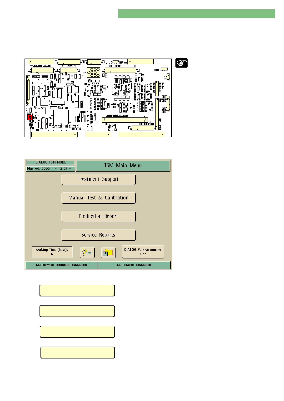
K1
Fig.: Suppervisor Board with Hardware Switch K1
The TSM Main Menu (TSM = Technical Support and
Maintenance) is used for servicing the machine.
The TSM service program (TSM Main Menu) is
started as follows:
1. Switch off machine.
2. Open rear door.
3. On supervisor board SB: turn hardware switch
K1 from position 0 to position 2position 2 .
Hardware Switch K1:Hardware Switch K1:
Position 0Position 0 = Therapy Mode
Position 2Position 2 = TSM Mode
Position 3Position 3 = Software Update Mode
4. Switch on machine.
The machine starts in TSM mode.
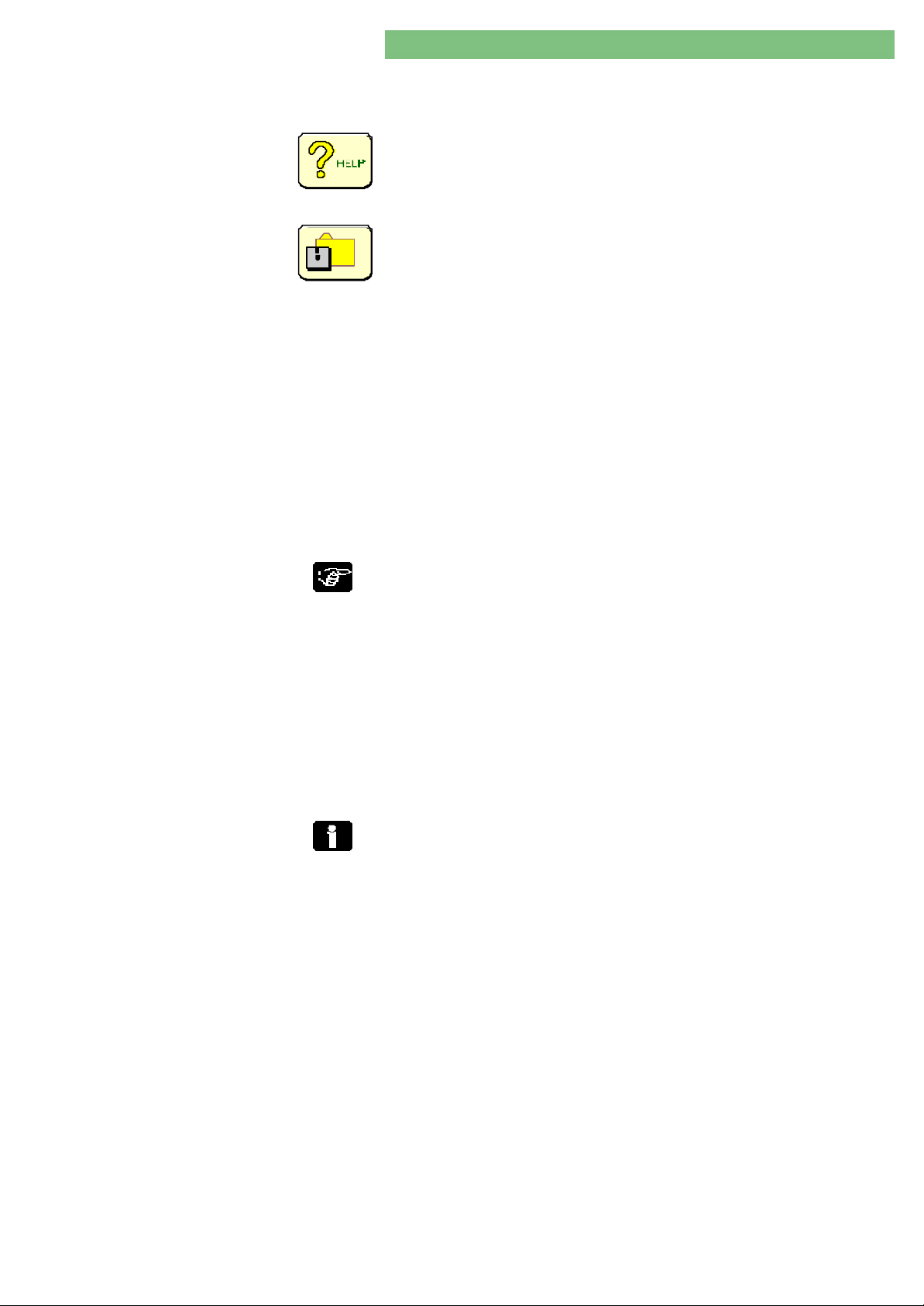
The TSM Main Menu is displayed. The following four
sub-menus can be selected:
Treatment Support
Manual Test & Calibration
•
Treatment Support
•
Manual Test and Calibration
•
Production Report
• Service Report
All basic parameters can be set for the therapy mode in the Treatment Support
menu.
All manual tests and calibrations can be performed in the Manual Test and
Calibration menu.
Production Report
Service Reports
MT-MD-DE08C M.KAY
DialogAd_sm_Chapter 4-1_6-2004.doc/pdf <120304> ddmmyy
All machine specific data and options are available in the Production Report
menu.
The Operation Mode Report menu can be selected in the Service Report menu.
B. Braun Medizintechnologie GmbH
Page 9
4. TSM Service Program 6/2004 4 9
Dialog/Dialog Advanced
Working Time Counter
Dialog Version Number
4.2 Quit TSM Service Program
The total working time of the Dialog is displayed in the Working Time Counter
window. The total working time is stored on the hard disk drive.
• Activate additional information with the HELP icon.
− Activate HELP icon
− Select a sub-menu via touch screen.
(A window with the help text is opened for the selected button.)
The File Operations menu (see paragraph 4.7) can be activated with the Diskette
icon. For example data can be loaded from diskette or saved to diskette.
Diskette FormatDiskette Format
From SW ≥ 6.XX (QNX 4) special diskettes for the QNX operating system do not
have to be generated. The diskettes for file operation are DOS/Windows
compatible, i.e. can be used in a PC with a DOS/Windows operating system.
Note:Note:
The format for patient diskettes and configuration diskettes (TSM) now have DOS
format, i.e. are not compatible with QNX 2 diskettes (SW < 6.20).
The actual Dialog software version is displayed in the Dialog version number
window (supported SW versions: 2.30/3.4X/ 5.XX/6.XX). The software versions
for the top and low level can be displayed and checked (this is also possible in
the production report).
4.3 QNX Operating System
QNX 2 Operating System A QNX 2 operating system is used for software ≤ 5.XX.
QNX 4 Operating System A QNX 4 operating system is used for software ≥ 6.20.
The following steps must be taken to quit the service program and to reenter the
therapy mode:
1. Switch off machine.
2. On supervisor board SB: turn hardware switch K1 from position 2 to positionposition
00 therapy mode.
3. Close rear door.
4. Switch on machine.
The machine starts in therapy mode.
Software ≥ 6.20
The format for patient diskettes and configuration diskettes (TSM) now
have DOS format, i.e. are not compatible with QNX 2 (SW < 6.20)
diskettes.
MT-MD-DE08C M.KAY
DialogAd_sm_Chapter 4-1_6-2004.doc/pdf <120304> ddmmyy
B. Braun Medizintechnologie GmbH
Page 10
Dialog/Dialog Advanced
4. TSM Service Program 6/2004 4 - 10
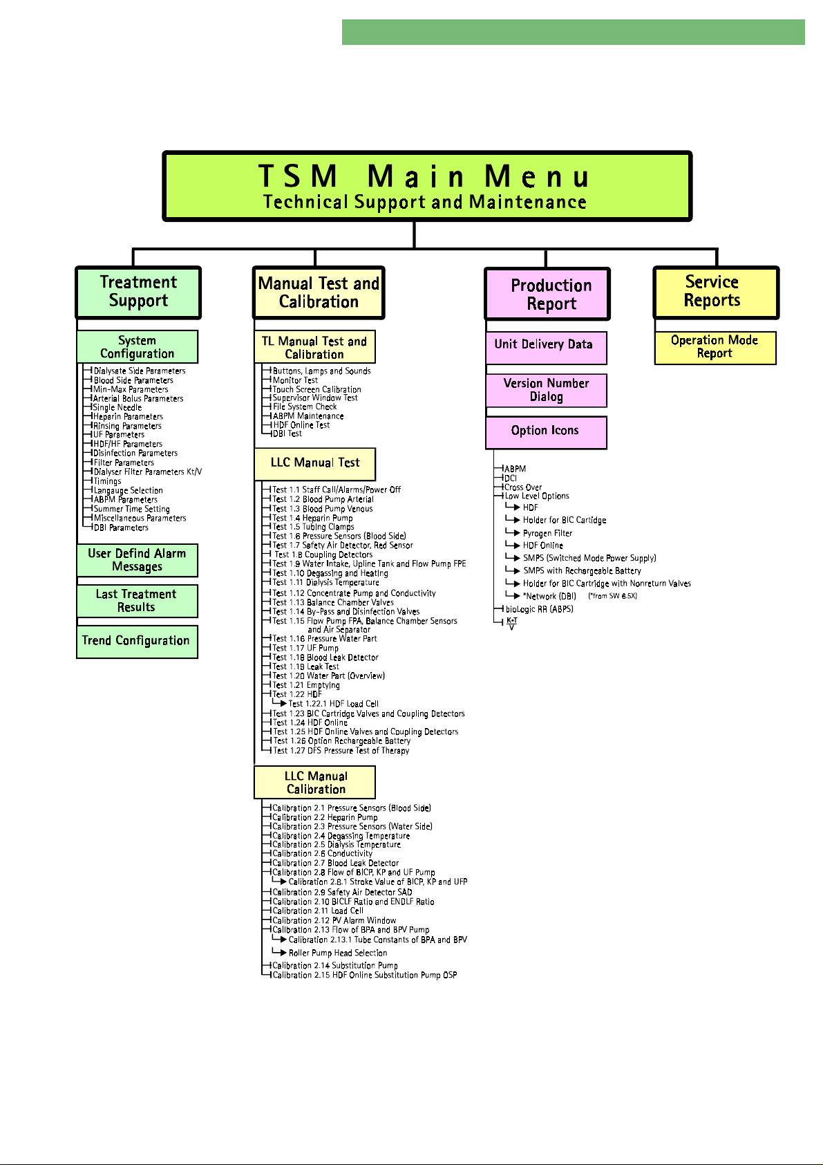
4.4 Structure of TSM Service Program Software 6.21
Fig. : TSM Service Program
MT-MD-DE08C M.KAY
DialogAd_sm_C ha pter 4-1_6-2004.doc/pdf <120304> ddmmyy
B. Braun Medizintechnologie GmbH
Page 11
4. TSM Service Program 6/2004 4 -
11
Dialog/Dialog Advanced
4.5 Service Overview in Therapy
Mode
General
Water TankWater Tank
RVVB: XX %
NSVB: TOP/MIDDLE/BOTTOM
DegassingDegassing
EP: XXXX rpm
RVE: XX %
PE: XXX mmHg
TSE: XX.X oC
HeaterHeater
HEATER: XX.X %
Air SeparatorAir Separator
LAFSO: NO AIR/AIR
LAFSU: NO AIR/AIR
VLA: OPEN/CLOSED
TemperatureTemperature
TSE: XX.X oC
TSBIC: XX.X oC
TSD: XX.X oC
TSD_S: XX.X oC
ConductivityConductivity
BICLF: X.X mS/cm
ENDLF: XX.X mS/cm
ENDLF_S: XX.X mS/cm
BICP: XX rpm
BICP_S: XX rpm
BIC-Ratio: XX.X
BIC-Ratio_S: XX.X
KP: XX rpm
KP_S: XX rpm
END-Ratio: XX.X
END-Ratio_S: XX.X
Balance ChamberBalance Chamber
MSBK1: XXXXX
MSBK2: XXXXX
VEBK1_S: OPEN/CLOSED
VABK1_S: OPEN/CLOSED
VDEBK2_S: OPEN/CLOSED
VDABK2_S: OPEN/CLOSED
VEBK2_S: OPEN/CLOSED
VABK2_S: OPEN/CLOSED
VDEBK1_S: OPEN/CLOSED
VDABK1_S: OPEN/CLOSED
Flow (DialysateFlow (Dialysate
FPE: XXXX rpm
FPA: XXXX rpm
FMD: XXX ml/min
FMD_S XXX ml/min
Valves BypassValves Bypass
VBP: OPEN/CLOSED
VBP_S: OPEN/CLOSED
VDE: OPEN/CLOSED
VDE_S: OPEN/CLOSED
VDA: OPEN/CLOSED
VDA_S: OPEN/CLOSED
Valves Valves DisinfectionDisinfection
VZ: OPEN/CLOSED
VD OPEN/CLOSED
VD_S OPEN/CLOSED
Blood LeakBlood Leak
BL: X.XX ‰
BL_S: X.XX ‰
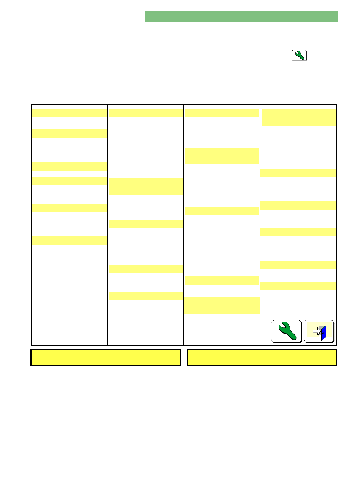
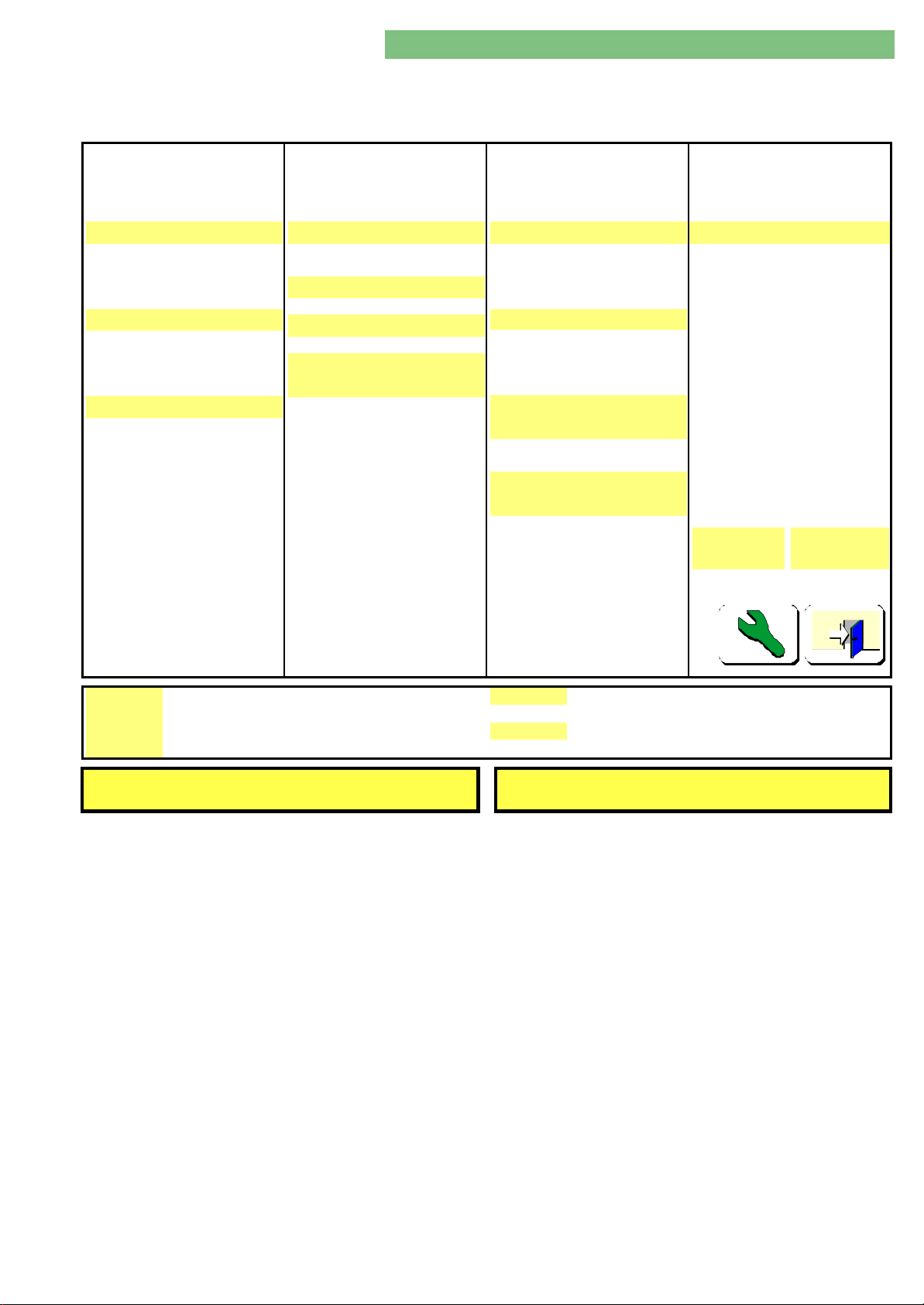
The service overview can be selected in therapy mode with the service key
icon.
The second page of the service overview can be selected with the service key
icon.
Click the Door icon to jump back to the initial menu.
Fluid)Fluid)
UltrafiltrationUltrafiltration
UFP: XX rpm
UFP_S: XX rpm
PDA: XXX mmHg
PDA_S: XXX mmHg
TMP: XXX mmHg
BIC CartridgeBIC Cartridge
HolderHolder
BKUS: OPEN/CLOSED
BKUS_S: OPEN/CLOSED
BKOS: OPEN/CLOSED
VVB: OPEN/CLOSED
VBICP: OPEN/CLOSED
VBKO: OPEN/CLOSED
VBKS: OPEN/CLOSED
Valves OnlineValves Online
VBE: OPEN/CLOSED
VBE_S: OPEN/CLOSED
VDFF: OPEN/CLOSED
VDFF_S: OPEN/CLOSED
VSB: OPEN/CLOSED
VSB_S: OPEN/CLOSED
VSAA: OPEN/CLOSED
VSAA_S: OPEN/CLOSED
VSAE: OPEN/CLOSED
VSAE_S: OPEN/CLOSED
Pump OnlinePump Online
OPS: XXXX rpm
OPS_S: XXXX rpm
Substitition FlowSubstitition Flow
Blood SideBlood Side
(Pressure)(Pressure)
PA: XXX mmHg
PA_S: XXX mmHg
PBE: XXX mmHg
PV: XXX mmHg
PV_S: XXX mmHg
PBS: XXX mmHg
PBS_S: XXX mmHg
Blood PumpsBlood Pumps
BPA: XXXX rpm
BPA_S: XXXX rpm
BPV: XXXX rpm
BPV_S: XXXX rpm
Tubing ClampsTubing Clamps
SAKA: OPEN/CLOSED
SAKV: OPEN/CLOSED
SAKV_S: OPEN/CLOSED
Air DetectorAir Detector
SAD: NO AIR/AIR
SAD_S: NO AIR/AIR
SAD TIME_S: OK
SAD REF_S: XXXX mV
HeparinHeparin
SYRDIA: XX.X mm
POSITION: XX.XX mm
Status SelftestStatus Selftest
LLC: XXXXX
LLS: XXXXX
OnlineOnline
FMS: XXX ml/min
FMS_S: XXX ml/min
LLC/S & TLC Alarm Window LLC Message Window
Fig.: First Page Service Overview in Therapy Mode
MT-MD-DE08C M.KAY
DialogAd_sm_Chapter 4-1_6-2004.doc/pdf <120304> ddmmyy
B. Braun Medizintechnologie GmbH
Page 12
4. TSM Service Program 6/2004 4 12
Dialog/Dialog Advanced
WTCWTC
Dialog - BasicDialog - Basic
RelayRelay
B24V_S: ON/OFF
D24V_S: ON/OFF
HEATER REL1_S: ON/OFF
HEATER REL2_S: ON/OFF
CouplingsCouplings
SBS1: COUPLED/UNCOUPLED
SBS2: COUPLED/UNCOUPLED
BIC_SS: COUPLED/UNCOUPLED
K_SS: COUPLED/UNCOUPLED
Red SensorRed Sensor
RDA: NO BLOOD/BLOOD
RDA_S: NO BLOOD/BLOOD
RDV: NO BLOOD/BLOOD
The first page of the service overview can be selected with the service key icon.
Click the Door icon to jump back to the initial menu.
HDF BagHDF Bag
WeightWeight
BAG: X g
BAG_S: X g
Flow DetectorFlow Detector
UF_FLOW: FLUSS/KEIN FLUSS
Air DetectorAir Detector
SUBAD: LUFT
SubstitutionSubstitution
VolumeVolume
SUBST: X ml
SUBST_S: X ml
SUBST_WV_S: X ml
SUM INF: X ml
ACT INF_S: X ml
INF LEAK_S X ml
HDF/HF-OnlineHDF/HF-Online
Reed SensorReed Sensor
PSAUS: OPEN/CLOSED
PSABF: OPEN/CLOSED
FDFS: OPEN/CLOSED
FHDFS: OPEN/CLOSED
HDF VolumeHDF Volume
HDF/HF_V: X.X l
HDF/HF_V_S: X.X l
BOLUS_VOL: X ml
BOLUS_VOL_S: X ml
Remaining FilterRemaining Filter
TimeTime
DF: X h
HDF: X h
RemainingRemaining
DialysisDialysis
DF: X
HDF: X
OthersOthers
SMPS BatterySMPS Battery
Batt. enabled: YES/NO
Selftest: NOT OK/OK
bioLogicbioLogic
LLC
ALARM:
LLS
ALARM:
0000 0000 0000 0000 0000 0000
0000 0000 0000 0000 0000 0000
MESSAGE:
FREE M:
0000 0000 0000 0000 0000 0000
XX.X (XX.X - XX.X) Mb
LLC/S & TLC Alarm Window LLC Message Window
Fig.: Second Page Service Overview in Therapy Mode
XXXXX h X
MT-MD-DE08C M.KAY
DialogAd_sm_Chapter 4-1_6-2004.doc/pdf <120304> ddmmyy
B. Braun Medizintechnologie GmbH
Page 13

4. TSM Service Program 6/2004 4 13
Dialog/Dialog Advanced
4.5.1 Legend Service Overview in
Therapy Mode
ACT INF_S: Actual infusion supervisor
B24V_S: 24 V cut-off blood side supervisor (HP, BPA, BPV)
BAG: Bag weight
BAG_S: Bag weight supervisor
BIC_SS: Bicarbonate rinsing connector sensor
BICLF: Bicarbonate conductivity
BICP: Bicarbonate pump
BICP_S: Bicarbonate pump supervisor
BIC-RATIO: Bicarbonate ratio
BIC-RATIO_S: Bicarbonate ratio supervisor
BKOS: BIC cartridge holder upper switch
BKUS: BIC cartridge holder lower switch
BKUS_S: BIC cartridge holder lower switch supervisor
BL: Blood leak detector
BL_S: Blood leak detector supervisor
BOLUS_VOL: Bolus volumen
BOLUS_VOL_S: Bolus volumen supervisor
BPA: Arterial blood pump
BPA_S: Arterial blood pump supervisor
BPV: Venous blood pump
BPV_S: Venous blood pump supervisor
D24V_S: 24 V cut-off dialysate side supervisor (VDA, VDE)
DF: Remaining time for DF
DF: Remaining time of dialysis for DF
ENDLF End conductivity
ENDLF_S End conductivity supervisor
END-RATIO: End ratio
END-RATIO_S: End ratio supervisor
EP: Degassing pump
F(E)DFS: Filter recognition DF filter sensor
F(E)HDFS: Filter recognition HD filter sensor
FMD: Flow measurement dialysate
FMD: Substitution flow measurement
FMD_S Flow measurement dialysate supervisor
FMD_S Substitution flow measurement supervisor
FPA: Outlet flow pump
FPE: Inlet flow pump
HDF/HF_V: HDF/HF volume
HDF/HF_V_S: HDF/HF volume supervisor
HDF: Remaining time for HDF
HDF: Remaining time of dialysis for HDF
HEATER REL1_S: Heater relay 1 supervisor
HEATER REL2_S: Heater relay 2 supervisor
HEATER Heater
INF LEAK_S: Infusion leakage supervisor
K_SS: Concentrate rinsing connector sensor
KP: Concentrate pump
KP_S: Concentrate pump supervisor
LAFSO: Top air separator level sensor
LAFSU: Bottom air separator level sensor
LLC: Low level controller
LLS: Low level supervisor
MSBK1: Membrane position sensor balance chamber 1
MSBK2: Membrane position sensor balance chamber 2
NSVB: Level sensors upline tank
OSP: Online substitution pump
OSP_S: Online substitution pump supervisor
PA: Arterial pressure sensor
PA_S: Arterial pressure sensor supervisor
PBS: Blood control pressure sensor
PBS_S: Blood control pressure sensor supervisor
MT-MD-DE08C M.KAY
DialogAd_sm_Chapter 4-1_6-2004.doc/pdf <120304> ddmmyy
B. Braun Medizintechnologie GmbH
Page 14

4. TSM Service Program 6/2004 4 14
Dialog/Dialog Advanced
PDA: Dialysate outlet pressure sensor
PDA_S: Dialysate outlet pressure sensor supervisor
PE: Degassing pressure sensor
POSITION: Drive position
PSABF(S): Substitution port drain sensor
PSAUS(S): Substitution port outlet sensor
PV: Venous pressure sensor
PV_S: Venous pressure sensor sup ervisor
RDA: Arterial red detector
RDA_S: Arterial red detector supervisor
RDV: Venous red detector
RVE: Degassing control valve
RVVB: Upline tank control valve
SAD REF_S: Safety air detector reference voltage supervisor
SAD TIME_S: Safety air detector time control supervisor
SAD: Safety air detector
SAD_S: Safety air detector supervisor
SAKA: Arterial tubing clamp
SAKV: Venous tubing clamp
SAKV_S: Venous tubing clamp supervisor
SBS1: Rinsing bridge connector sensor 1
SBS2: Rinsing bridge connector sensor 2
SUBAD: Substitution air detector
SUBST: Substitution
SUBST_S: Substitution supervisor
SUBST_WV_S Substitution weight volum supervisor
SUM INF: Sum infusion
SYR_DIA: Syringe diameter
TMP: Transmembrane pressure
TSBIC Bicarbonate temperature sensor
TSD Dialysate temperature sensor
TSD_S Dialysate temperature sensor supervisor
TSE Degassing temperature sensor
TSE Degassing temperature sensor
UF_Flow: Ultrafiltration flow
UFP: Ultrafiltration pump
UFP_S: Ultrafiltration pump supervisor
VABK1_S: Outlet valve balance chamber 1 supervisor
VABK2_S: Outlet valve balance chamber 2 supervisor
VBE: Vent filter valve
VBE_S: Vent filter valve supervisor
VBICP: BIC pump valve
VBKO: BIC cartridge holder top Valve
VBKS: BIC cartridge holder concentrate rod valve
VBP: Bypass valve
VBP_S: Bypass valve supervisor
VD Disinfection valve supervisor
VDA: Dialyser outlet valve
VDABK1_S: Dialyser outlet valve balance chamber 1 supervisor
VDABK2_S: Dialyser outlet valve balance chamber 2 supervisor
VDA-S: Dialyser outlet valve supervi sor
VDE: Dialyser inlet valve
VDEBK1_S: Dialyser inlet valve balance chamber 1 supervisor
VDEBK2_S: Dialyser inlet valve balance chamber 2 supervisor
VDE-S: Dialyser inlet valve supervisor
VDFF: DF filter valve
VDFF_S: DF filter valve supervisor
VEBK1_S: Inlet valve balance chamber 1 supervisor
VEBK2_S: Inlet valve balance chamber 2 supervisor
VLA: Air separator valve
VSAA: Substitution outlet valve
VSAA_S: Substitution outlet valve supervisor
VSAE: Substitution inlet valve
MT-MD-DE08C M.KAY
DialogAd_sm_Chapter 4-1_6-2004.doc/pdf <120304> ddmmyy
B. Braun Medizintechnologie GmbH
Page 15

4. TSM Service Program 6/2004 4 15
Dialog/Dialog Advanced
VSAE_S: Substitution inlet valve supervisor
VSB: Substitution bypass valve
VSB_S: Substitution bypass valve supervisor
VVB: Upline tank valve
VZ: Circulation valve
Working Time Counter
bioLogic RR
LLC ALARM
LLS ALARM
LLC MESSAGE
FREE MEMORY
LLC/S & TLC Alarm Window • L ow level controller alarm text Window messages according to the LLC
Working time counter (WTC)
bioLogic RR 0ption
The low level controller alarms are displayed in a hexadecimal format. The
corresponding bit alarms are shown in the LLC alarm window.
The low level supervisor alarms are displayed in a hexadecimal format. The
corresponding bit alarms are shown in the LLS alarm window.
The LLC messages are displayed in a hexadecimal format. The corresponding bit
messages are shown in the message window.
Free RAM memory (DIMM/SIMM).
hex numbers from the LLC alarm window.
• L ow level supervisor alarm text Window messages according to the LLS
hex numbers from the LLS alarm window.
LLC Message Window
• Top level controller alarm messages Window according to the TLC hex
numbers from the TLC alarm window.
LLC text messages according to the LLC message hex numbers from LLC message
window.
MT-MD-DE08C M.KAY
DialogAd_sm_Chapter 4-1_6-2004.doc/pdf <120304> ddmmyy
B. Braun Medizintechnologie GmbH
Page 16
4. TSM Service Program 6/2004 4 16
Dialog/Dialog Advanced
4.6 Service Overview in TSM
Service Program
General
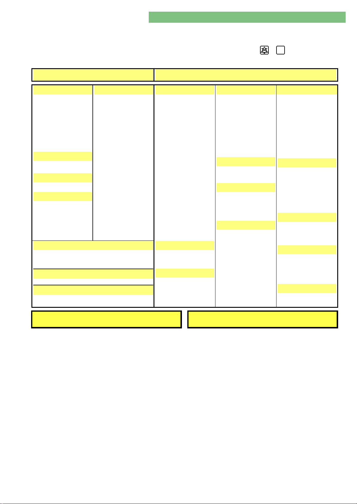
The service overview can be selected with the /
program.
Required Data to LLC Actual Data from LLC
PUMP
BICP: X
BPA: X
BPV: X
EP: X
FPA: X
FPE: X
KP: X
UFP: X
HEATER
H: X
SAD
SAD_LEVEL: X
ACTIONS
LEAKTEST: ON/OFF
EMPTYING: ON/OFF
BL_LAMP_T: ON/OFF
SAD_TEST: ON/OFF
AUTOMATIC TEST & CALIBRATION
LF: X.XX PA: X
TSD: X.X PDA: X
TSE: X.X
WORKING TIME COUNTER
WTC: X
FREE MEMORY (Mb)
XXXX [XX.X-XX.XX] Mb
VALVE
RVE: X
RVVB: X
VABK1: OPEN/CLOSED
VDABK1: OPEN/CLOSED
VEBK1: OPEN/CLOSED
VDEBK1: OPEN/CLOSED
VABK2: OPEN/CLOSED
VDABK2: OPEN/CLOSED
VEBK2: OPEN/CLOSED
VDEBK2: OPEN/CLOSED
VBP: OPEN/CLOSED
VDE: OPEN/CLOSED
VDA: OPEN/CLOSED
VD OPEN/CLOSED
VZ: OPEN/CLOSED
VLA: OPEN/CLOSED
VDFF: OPEN/CLOSED
VSB: OPEN/CLOSED
VBE OPEN/CLOSED
VSAE: OPEN/CLOSED
VSAA: OPEN/CLOSED
PUMP
BPA: X
BPAIMP_S: X
BPA_FLOW: X
BPA_COVER:OPEN/CLOSED
BPV: X
BPVIMP_S: X
BPV_COVER:OPEN/CLOSED
EP: X
FPE: X
FPA: X
UFP_S: X
UFP_FLOW: X.X
UFP_FLOW_S: X.X
BICP_S: X
BICP_FLOW: X.X
BICP_FLOW_S: X.X
KP_S: X
KP_FLOW: X.X
KP_FLOW_S: X.X
HP_POS: X.X
HPKOLB: ON/OFF
HPKRALLO: OPEN/CLOSED
BLOOD LEAK
BLCON: X.XXX
BLCON_S: X.XXX
SAD
SAD_LEVEL: XX
SAD_LEV_S: X.XXX
SAD: AIR/BLOOD
SAD_S: AIR/BLOOD
PRESSURE
PA: X
PA_S: X
PV: X
PV_S: X
PBE: X
PBS: X
PBS_S: X
PDA: X
PDA_S: X
PE: X
LEVEL
NSVB: HIGH/MIDDLE/LOW
LAFS: HIGH/MIDDLE/LOW
TEMPERATURE
TSE XX.X
TSBIC XX.X
TSD XX.X
TSD_S XX.X
VALVE
VBP_S: OPEN/CLOSED
VDE_S: OPEN/CLOSED
VDA_S: OPEN/CLOSED
VD_S OPEN/CLOSED
VZ_S: OPEN/CLOSED
VLA_S: OPEN/CLOSED
VDFF_S: OPEN/CLOSED
VSB_S: OPEN/CLOSED
VBE_S: OPEN/CLOSED
VSAE_S: OPEN/CLOSED
VSAA_S: OPEN/CLOSED
AQ
key in the TSM service
BALANCE CHAMBER
MSBK1: X
MSBK2: X
VABK1_S: OPEN/CLOSED
VDABK1_S: OPEN/CLOSED
VEBK1_S: OPEN/CLOSED
VDEBK1_S: OPEN/CLOSED
VABK2_S: OPEN/CLOSED
VDABK2_S: OPEN/CLOSED
VEBK2_S: OPEN/CLOSED
VDEBK2_S: OPEN/CLOSED
COUPLINGS
BIC_SS: OPEN/CLOSED
K_SS: OPEN/CLOSED
SBS1: OPEN/CLOSED
SBS2: OPEN/CLOSED
BICKARTS: OPEN/CLOSED
BICKARTS_S:
OPEN/CLOSED
CONDUCTIVITY
BICLF: X.XX
ENDLF X.XX
ENDLF_S X.XX
STATUS
RDA: NO BLOOD/BLOOD
RDA_S NO BLOOD/BLOOD
RDV: NO BLOOD/BLOOD
RDV_S NO BLOOD/BLOOD
POWER
B24VOFF: ON/OFF
D24VOFF: ON/OFF
LLC STATUS: 00000000 0000000 LLS STATUS: 00000000
Fig.: Service Overview in TSM Mode
MT-MD-DE08C M.KAY
DialogAd_sm_Chapter 4-1_6-2004.doc/pdf <120304> ddmmyy
B. Braun Medizintechnologie GmbH
Page 17

4. TSM Service Program 6/2004 4 17
Dialog/Dialog Advanced
4.6.1 Legend Service Overview in
TSM Service Program
B24VOFF: 24 V cut-off blood side (HP, BPA, BPV)
BIC_SS: Bicarbonate rinsing connector sensor
BICKART: Bicarbonate cartridge
BICKART_S: Bicarbonate cartridge supervisor
BICLF: Bicarbonate conductivity
BICP: Bicarbonate pump
BICP_FLOW: Bicarbonate pump flow
BICP_FLOW_S: Bicarbonate pump flow supervisor
BICP_S: Bicarbonate pump supervisor
BL_LAMP_T: Blood leak detector lamp test
BLCON: Blood leak detector
BLCON_S: Blood leak detector supervisor
BPA: Arterial blood pump
BPA_COVER: Arterial blood pump cover
BPA_FLOW: Arterial blood pump flow
BPAIMP_S: Arterial blood pump pulse supervisor
BPV: Venous blood pump
BPV_COVER: Venous blood pump cover
BPVIMP_S: Venous blood pump pulse supervisor
D24VOFF: 24 V cut-off dialysate side (VDA, VDE)
EMPTYING: Emptying
ENDLF End conductivity
ENDLF_S End conductivity supervisor
EP: Degassing pump
FPA: Outlet flow pump
FPE: Inlet flow pump
Free Memory Free RAM memory (DIMM/SIMM)
H: Heater
HP_POS: Heparin pump drive position
HPKOLB: Heparin pump plate sensor
HPKRALLO: Heparin pump claws
K_SS: Concentrate rinsing connector sensor
KP: Concentrate pump
KP_FLOW: Concentrate pump flow
KP_FLOW_S: Concentrate pump flow supervisor
KP_S: Concentrate pump supervisor
LAFS: Air separator level sensors
LEAKTEST: Leakage test
LF: Conductivity sensor
LLC STATUS Alarm messages low level controller
LLS STATUS Alarm messages low level supervisor
MSBK1: Membrane position sensor balance chamber 1
MSBK2: Membrane position sensor balance chamber 2
NSVB: Level sensor upline tank
PA: Arterial pressure sensor
PA_S: Arterial pressure sensor supervisor
PBE: Blood inlet pressure sensor
PBS: Blood control pressure sensor
PBS_S: Blood control pressure sensor supervisor
PDA: Dialysate outlet pressure sensor
PDA: Dialysate outlet pressure sensor
PDA_S: Dialysate outlet pressure sensor supervisor
PE: Degassing pressure sensor
PV: Venous pressure sensor
PV_S: Venous pressure sensor supervisor
MT-MD-DE08C M.KAY
DialogAd_sm_Chapter 4-1_6-2004.doc/pdf <120304> ddmmyy
B. Braun Medizintechnologie GmbH
Page 18

4. TSM Service Program 6/2004 4 18
Dialog/Dialog Advanced
RDA: Arterial red detector
RDA_S Arterial red detector supervisor
RDV: Venous red detector
RDV_S Venous red detector supervisor
RVE: Degassing control valve
RVVB: Upline tank control valve
SAD: Safety air detector
SAD_LEV_S: Safety air detector supervisor level (voltage)
SAD_LEVEL: Safety air detector level
SAD_LEVEL: Safety air detector level (digits)
SAD_S: Safety air detector supervisor
SAD_TEST: Safety air detector test
SBS1: Rinsing bridge connector sensor 1
SBS2: Rinsing bridge connector sensor 2
TSBIC Bicarbonate temperature sensor
TSD: Dialysate temperature sensor
TSD_S Dialysate temperature sensor supervisor
TSE: Degassing temperature sensor
UFP: Ultrafiltration pump
UFP_FLOW: Ultrafiltration pump flow
UFP_FLOW_S: Ultrafiltration pump flow supervisor
UFP_S: Ultrafiltration pump supervisor
VABK1: Outlet valve balance chamber 1
VABK1_S: Outlet valve balance chamber 1 supervisor
VABK2: Outlet valve balance chamber 2
VABK2_S: Outlet valve balance chamber 2 supervisor
VBE: Filter vent valve
VBE_S: Vent filter valve supervisor
VBP: By-pass valve
VBP_S: By-pass valve supervisor
VD Disinfection valve
VD_S Disinfection valve supervisor
VDA: Dialyser outlet valve
VDABK1: Dialyser outlet valve balance chamber 1
VDABK1_S: Dialyser outlet valve balance chamber 1 supervisor
VDABK2: Dialyser outlet valve balance chamber 2
VDABK2_S: Dialyser outlet valve balance chamber 2 supervisor
VDA-S: Dialyser outlet valve supervisor
VDE: Dialyser inlet valve
VDEBK1: Dialyser inlet valve balance chamber 1
VDEBK1_S: Dialyser inlet valve balance chamber 1 supervisor
VDEBK2: Dialyser inlet valve balance chamber 2
VDEBK2_S: Dialyser inlet valve balance chamber 2 supervisor
VDE-S: Dialyser inlet valve supervisor
VDFF: DF filter valve
VDFF_S: DF filter valve supervisor
VEBK1: Inlet valve balance chamber 1
VEBK1_S: Inlet valve balance chamber 1 supervisor
VEBK2: Inlet valve balance chamber 2
VEBK2_S: Inlet valve balance chamber 2 supervisor
VLA: Air separator valve
VLA_S: Air separator valve supervisor
VSAA: Substitution outlet valve
VSAA_S: Substitution outlet valve supervisor
VSAE: Substitution inlet valve
VSAE_S: Substitution inlet valve supervisor
VSB: Substitution bypass valve
VSB_S: Substitution bypass valve supervisor
VZ: Circulation valve
VZ_S: Circulation valve supervisor
WTC: Working time counter
MT-MD-DE08C M.KAY
DialogAd_sm_Chapter 4-1_6-2004.doc/pdf <120304> ddmmyy
B. Braun Medizintechnologie GmbH
Page 19
4. TSM Service Program 6/2004 4 19
Dialog/Dialog Advanced
4.7 File Operations SW < 6.20
1. Set TSM service program mode on supervisor
board: hardware switch K1, position 2.
2. Switch on Dialog.
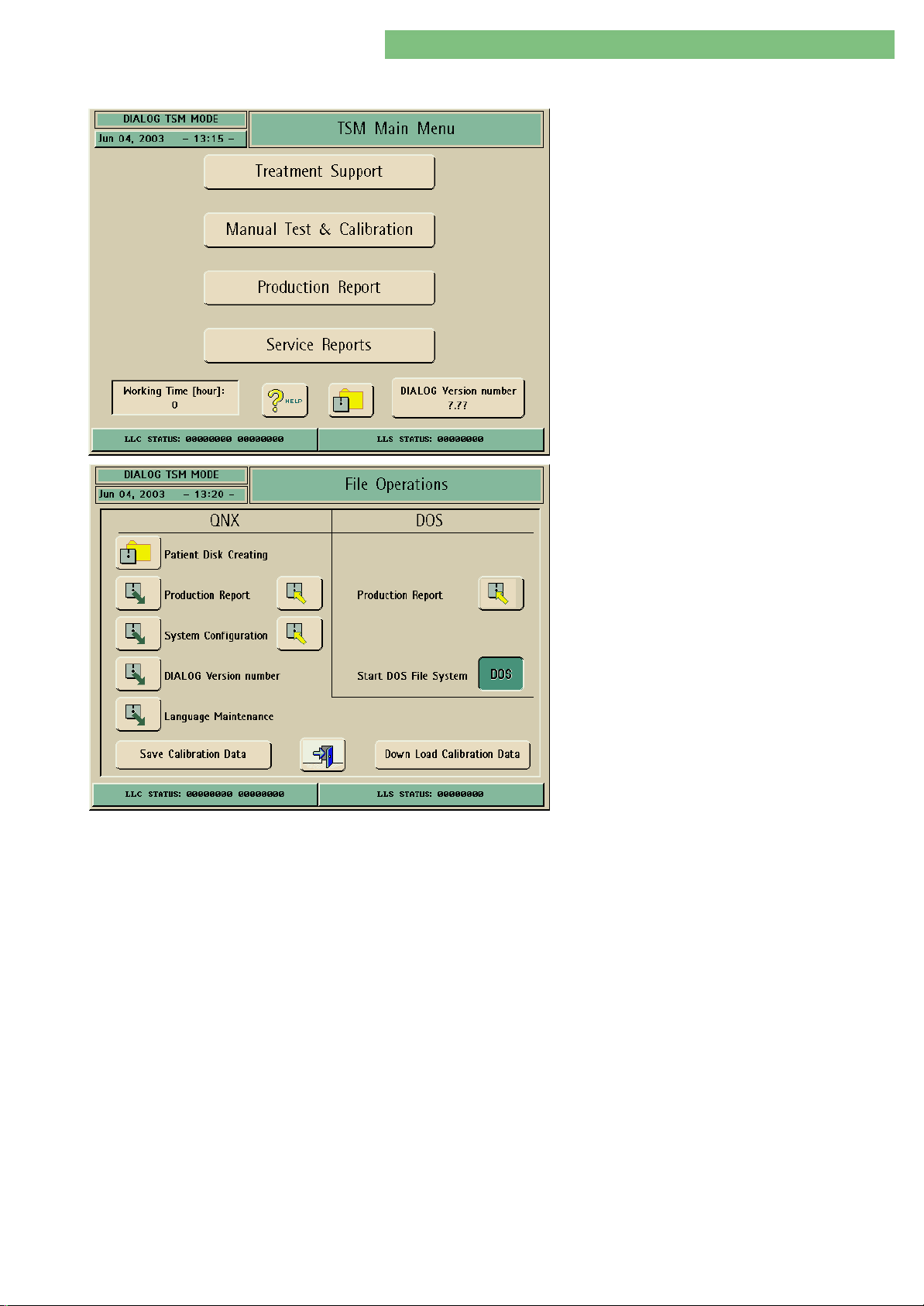
3. Activate the File Operations menu with the
Diskette icon in menu TSM Main Menu.
The File Operations menu is displayed. The following
parameters can be selected:
QNX 2 File Operations
• Patient Disk Creating
• Production Report
• System Configuration
• Dialog Version Number
• Language Maintenance
4.7.1 QNX File Operations
Patient Disk Creating
Production Report
DOS File Operations
• Production Report
• Start DOS File System
Save Calibration Data Low Level Controller (LLC)
Down Load Calibration Data Low Level
Controller (LLC)
You can format a QNX diskette with the icon. The patient name is checked on the
diskette. Thus it is guaranteed that other patient diskettes are not overwritten.
1. Insert a non-formatted diskette or DOS formatted diskette into floppy disk
drive.
2. Select Diskette icon.
3. Format QNX diskette.
You can load a production report from a diskette or save the production report to
a diskette.
1. Insert an empty QNX diskette or a diskette with the production report into
floppy disk drive.
MT-MD-DE08C M.KAY
DialogAd_sm_Chapter 4-1_6-2004.doc/pdf <120304> ddmmyy
2. Select Diskette icon.
3. Load or store the production report.
B. Braun Medizintechnologie GmbH
Page 20
4. TSM Service Program 6/2004 4 20
Dialog/Dialog Advanced
System Configuration
Dialog Version Number
Language Maintenance
Language for Treatment
You can load the basic setting TSM/therapy from diskette or save the basic setting
TSM/therapy to a diskette.
A diskette with the system configuration from an other machine canA diskette with the system configuration from an other machine can
only be used if the hardware, the software and the operating systemonly be used if the hardware, the software and the operating system
(QNX2 or QNX4) match.(QNX2 or QNX4) match.
1. Insert an empty QNX diskette or a diskette with the system configuration into
floppy disk drive.
2. Select Diskette icon.
3. Load or store the system configuration.
You can load a new Dialog version no., e.g. due to a controller software update.
1. Insert Dialog version number diskette into floppy disk drive.
2. Select Diskette icon.
3. Load new version number.
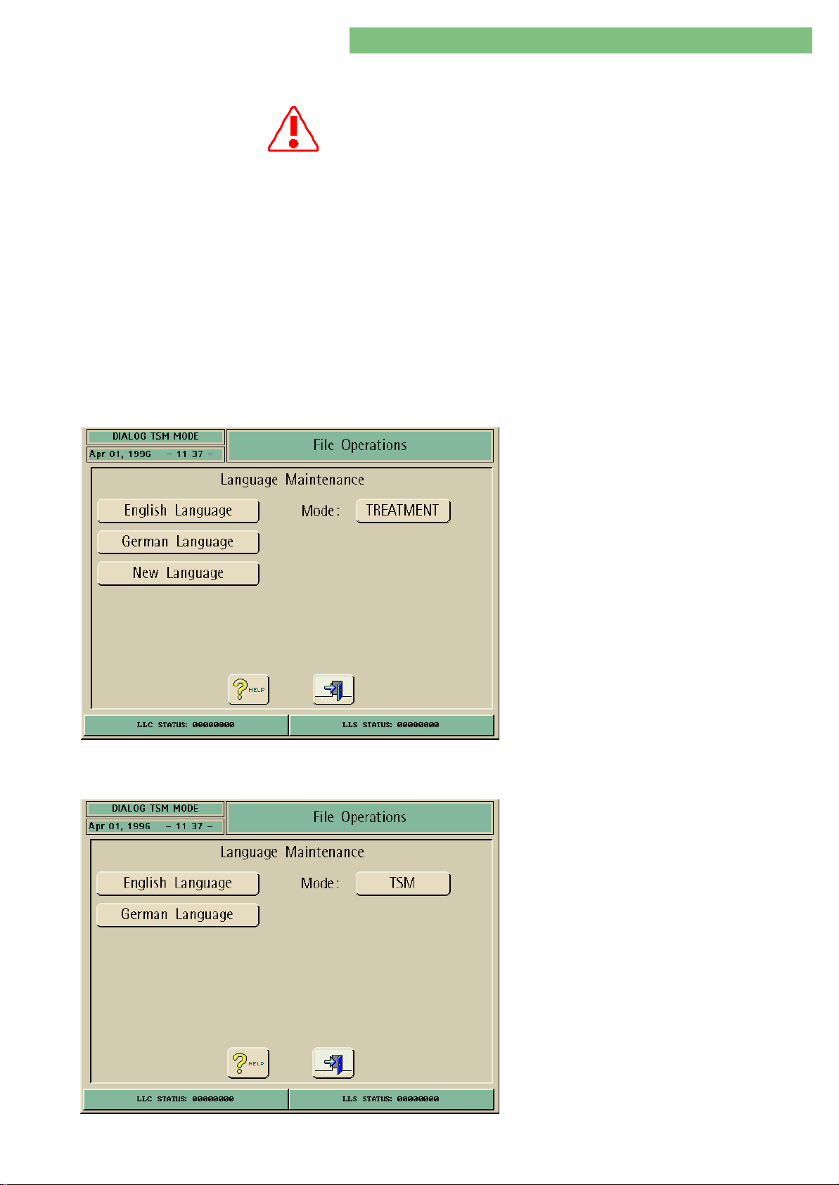
You can load or supplement a new language for therapy or TSM service program.
1. Insert language diskette into floppy disk drive.
2. Select Diskette icon.
Language for TSM Service Program
3. Select the English Language, German Language
or the New Language button to install the
appropriate language.
1. Select TSM with the Mode button.
2. Insert language diskette into floppy disk drive.
3. Select the English Language or the German
Language button to install the appropriate
language.
MT-MD-DE08C M.KAY
DialogAd_sm_Chapter 4-1_6-2004.doc/pdf <120304> ddmmyy
B. Braun Medizintechnologie GmbH
Page 21

4. TSM Service Program 6/2004 4 21
Dialog/Dialog Advanced
4.7.2 DOS File Operations
STK Report
Production Report
4.7.3 Calibration Data Operations
Save Calibration Data
Low Level Controller LLC
Down Load Calibration Data
Low Level Controller LLC
This function is not supported.
You can save the production report to a DOS diskette. The DOS compatible file
name has eight characters, for the serial number of the specific Dialog unit and
prd file recognition. File name, date, year and time are protocolled in the report.
Example file name:
Dialog Serial No.: 2001 File Name: 00002001.prd
1. Insert DOS diskette into floppy disk drive.
2. Select Diskette icon.
3. Save production list to diskette.
The calibration data must be saved to the hard disk drive by LLC/LLS after every
calibration.
The LLC calibration data can be downloaded from the hard disk drive to the
exchanged controller board LLC.
Note Exchange Supervisor Board
The procedure for the exchange of a supervisor board is different (details see
chapter 3 repair instructions).
MT-MD-DE08C M.KAY
DialogAd_sm_Chapter 4-1_6-2004.doc/pdf <120304> ddmmyy
B. Braun Medizintechnologie GmbH
Page 22
4. TSM Service Program 6/2004 4 22
Dialog/Dialog Advanced
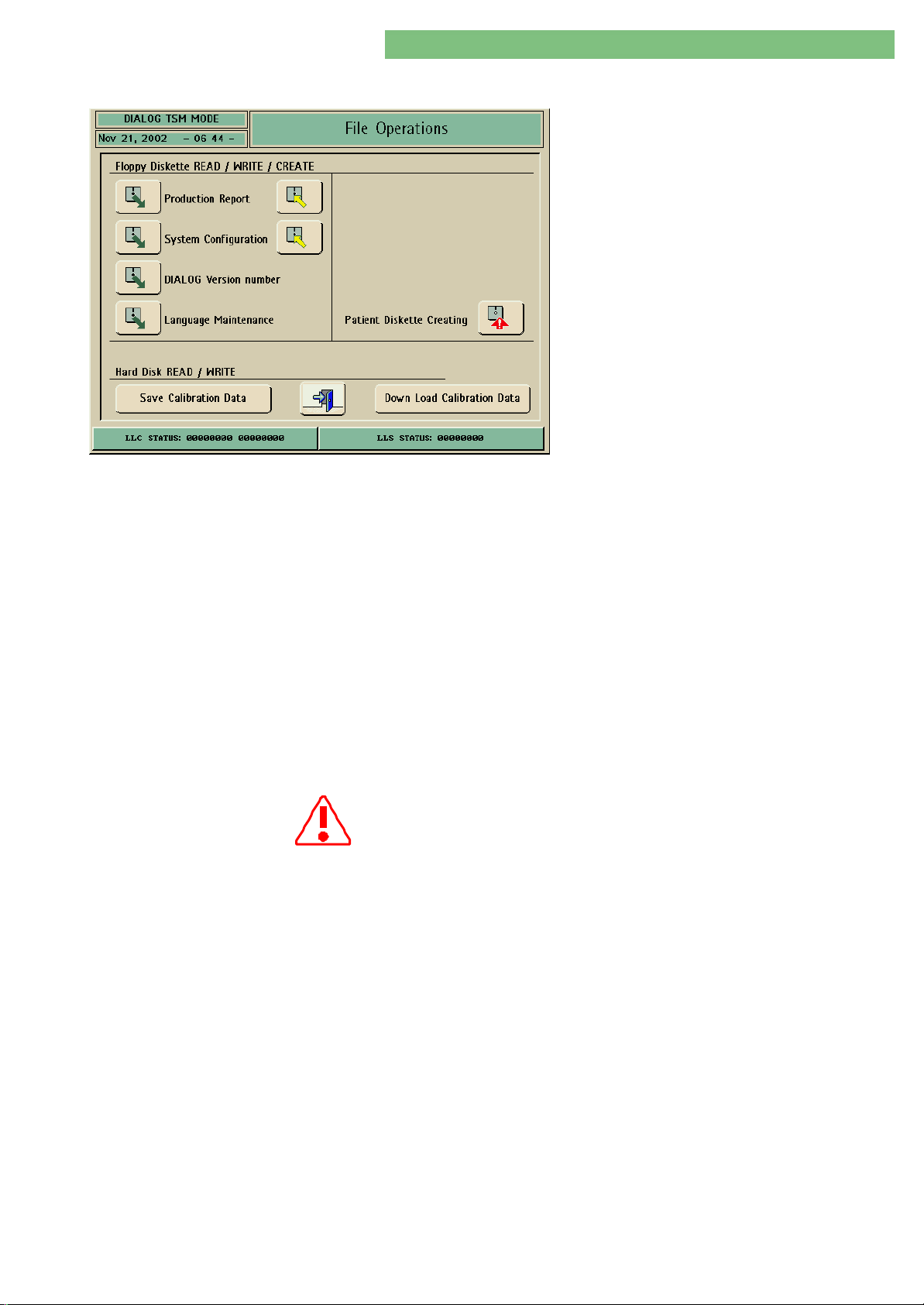
4.8 File Operations SW ≥ 6.20
The File Operations menu is selected with the
Diskette icon in the TSM main menu.
Note
The format for patient diskettes and
configuration diskettes (TSM) now have DOS
format, i.e. are not compatible with QNX 2 (SW
< 6.20) diskettes.
From QNX 4 special diskettes for the QNX operating
system do not have to be generated. The diskettes
for file operation are DOS compatible, i.e. can be
used in a PC with a DOS/Windows operating system.
The following parameters can be selected:
Floppy Diskette Read/Write/Create
• Production Report
• System Configuration
• Dialog Version Number
• Language Maintenance
• Patient Diskette Creating
Hard Disk Read/Write
• Save Calibration Data
• Down Load Calibration Data
4.8.1 Floppy Diskette Operations
Production Report
System Configuration
Dialog Version Number
You can load a production report from a diskette or save the production report to
diskette.
1. Insert a formatted DOS diskette or a diskette with the production report into
floppy disk drive.
2. Select Diskette icon.
3. Load or store the production report.
You can load the basic setting TSM/therapy from diskette or save the basic setting
TSM/therapy to diskette.
A diskette with the system configuration from an other machine canA diskette with the system configuration from an other machine can
only be used if the hardware, the software and the operating systemonly be used if the hardware, the software and the operating system
(QNX2 or QNX4) match.(QNX2 or QNX4) match.
1. Insert a formatted DOS diskette or a diskette with the system configuration
into floppy disk drive.
2. Select floppy disc icon.
3. Load or store the basic setting.
You can load a new Dialog version no., e.g. due to a controller software update
1. Insert Dialog version number diskette into floppy disk drive.
MT-MD-DE08C M.KAY
DialogAd_sm_Chapter 4-1_6-2004.doc/pdf <120304> ddmmyy
Patient Diskette Creating
2. Select Diskette icon.
3. Load new version number.
You can create a patient diskette (DOS).
1. Insert DOS formatted diskette into floppy disk drive.
2. Select Patient Diskette Creating icon.
A DOS formatted patient diskette is created.
B. Braun Medizintechnologie GmbH
Page 23
4. TSM Service Program 6/2004 4 23
Dialog/Dialog Advanced
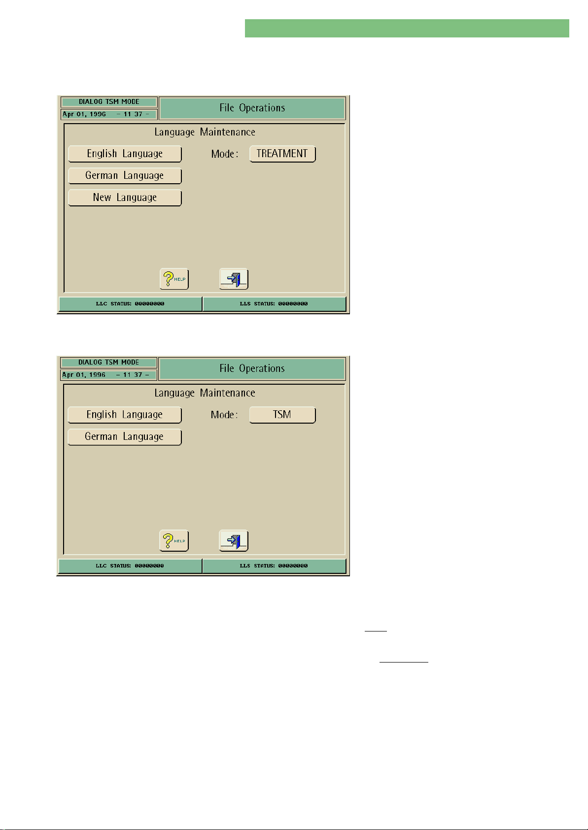
Language Maintenance
Language for Treatment
You can load or supplement a new language for therapy or for the TSM service
program.
1. Insert language diskette into floppy disk drive.
2. Select Diskette icon.
3. Select the English Language, German Language
or the New Language button to install the
appropriate language.
Language for TSM Service Program
4.8.2 Calibration Data Operations
1. Select TSM with the Mode button.
2. Insert language Diskette into floppy disk drive.
3. Select the English Language or the German
Language button to install the appropriate
language.
Down Load Calibration Data
MT-MD-DE08C M.KAY
DialogAd_sm_Chapter 4-1_6-2004.doc/pdf <120304> ddmmyy
Save Calibration Data
Low Level Controller LLC
Low Level Controller LLC
The calibration data must be saved to the hard disk drive by LLC/LLS after every
calibration.
The LLC calibration data can be downloaded from the hard disk drive to the
exchanged controller board LLC.
Note Exchange Supervisor BoardNote Exchange Supervisor Board
The procedure for the exchange of a supervisor board is different (details see
chapter 3 repair instructions).
B. Braun Medizintechnologie GmbH
Page 24
4. TSM Service Program 6/2004 4 24
Dialog/Dialog Advanced
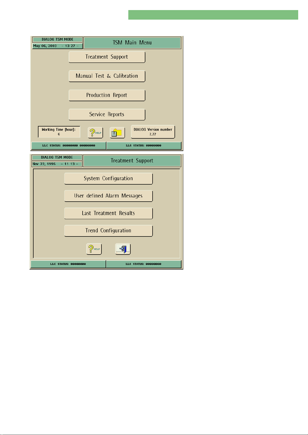
4.9 Treatment Support
1. Activate the Treatment Support menu with the
Treatment Support button in menu TSM Main
Menu. The following menu is opened.
Four sub-menus can be selected in the Treatment
Support menu.
User Defined Alarm Messages
MT-MD-DE08C M.KAY
DialogAd_sm_Chapter 4-1_6-2004.doc/pdf <120304> ddmmyy
System Configuration
Last Treatment Results
Trend Configuration
This is a special editor to set the configuration of the treatment mode (e.g. limits,
default values). The new settings are valid after the restart of the machine.
Every alarm message has of two parts. The first Fix Alarm message is a
noneditable alarm description. The second User Alarm message can be edited by
the user for additional remarks (only available in some SW versions).
You can select and define the configuration of the trends displayed in treatment
mode. The stored data of the last treatment can be displayed with the second
function.
There are five trend groups, which can be selected for the treatment program.
Every group has three treatment parameters.
B. Braun Medizintechnologie GmbH
Page 25
4. TSM Service Program 6/2004 4 25
Dialog/Dialog Advanced
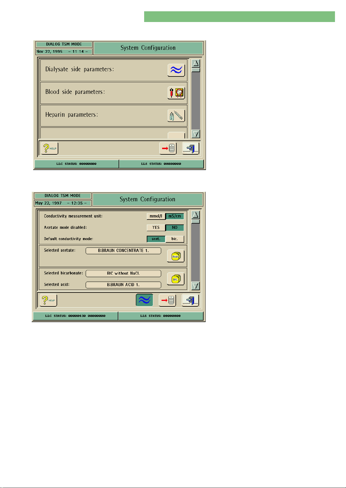
4.9.1 System Configuration
4.9.1.1 Dialysate Side Parameters
1. Activate the System Configuration menu with
the System Configuration button in menu
Treatment Support.
The following menu is opened.
Scroll the various system configuration points up or
down with the scroll bar. System configuration
points can be selected (additional settings are
activated if specific options are selected).
Conductivity Measurement Unit
The dialysate fluid parameters can be set in the
Dialysate Side Parameters menu.
1. Activate the Dialysate Side Parameters menu
with the Dialysate Side Parameters icon. The
following menu is opened.
The following parameters can be set:
• Conductivity measurement unit
• Acetate mode disabled
• Default conductivity mode
• Selected acetate (only necessary if mmol/l is
selected)
• Selected bicarbonate/selected acid (only
necessary if mmol/l is selected)
• Temperature measurement unit
• Dialysate flow
• Dialysate temperature
You can either select conductivity [mS/cm] or sodium concentration [mmol/l] for
the conductivity measurement unit. If sodium concentration [mmol/l] is selected
a corresponding conversion factor must be entered. Activate the ACET or BIC icon
to enter the corresponding conversion factor.
1. Click the mmol/l or mS/cm button to select a measurement unit.
Acetate Mode Disabled
Default Conductivity Mode
MT-MD-DE08C M.KAY
DialogAd_sm_Chapter 4-1_6-2004.doc/pdf <120304> ddmmyy
The acetate mode can be disabled.
1. Click the YES button to disable the acetate mode.
The bicarbonate dialysis is the standard factory setting. You can preselect either
acetate or bicarbonate for the standard dialysis operation mode.
1. Click either the Bic or Acet button for the standard setting.
B. Braun Medizintechnologie GmbH
Page 26
4. TSM Service Program 6/2004 4 26
Dialog/Dialog Advanced
Selected Acetate
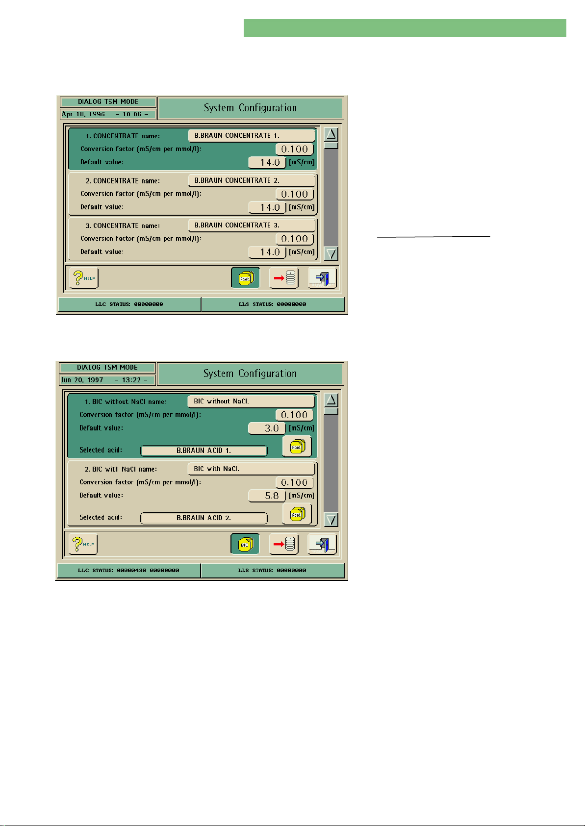
You can enter up to 10 acetate concentrate names and the conversion factors
for the conversion of conductivity values for concentrate of sodium ions. You can
activate a concentrate for therapy by pressing a free section of the window.
1. Click the Acet icon to activate the selected
acetate. The following menu is opened.
2. Click the Concentrate window to enter or to edit
a concentrate name. This name is displayed in
therapy mode.
3. Click the Conversion window if necessary to
enter or to change the conversion factor
[mS/cm per mmol/l].
Conversion Factor:
Conductivity Value LF (Standard Value)
Measured Value (NaCl Concentration)
Conversion Factor
4. Click the Default Value window if you want to
change the value [mS/cm].
Selected Bicarbonate/Selected Acid
You can activate a window for BIC without or with NaCl by pressing a free section
of the window. You can select the current bicarbonate type with or without NaCl:
• Bicarbonate without NaCl (2 - 4 mS/cm)
• Bicarbonate with NaCl (4 - 7 mS/cm)
Do not activate Bicarbonate with NaCl if the BIC
cartridge holder option is installed and applied.
This setting is used in therapy. If necessary you can
set the name and the conversion factor [mS/cm per
mmol/l] for the applied bicarbonate type.
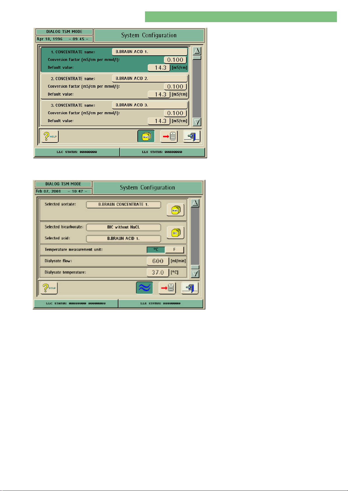
1. Click the BIC icon to activate the selected
bicarbonate.
The following menu is opened.
2. Click the Bicarbonate window to enter or to edit
a bicarbonate name.
3. Click the Conversion window if necessary to
enter or to change the conversion factor
[mS/cm per mmol/l].
4. You can select the current acetate concentrate.
Enter the name and the conversion factor
[mS/cm per mmol/l] for the different acetate
concentrates.
MT-MD-DE08C M.KAY
DialogAd_sm_Chapter 4-1_6-2004.doc/pdf <120304> ddmmyy
5. The conversion factor is calculated like acetate.
B. Braun Medizintechnologie GmbH
Page 27
4. TSM Service Program 6/2004 4 27
Dialog/Dialog Advanced
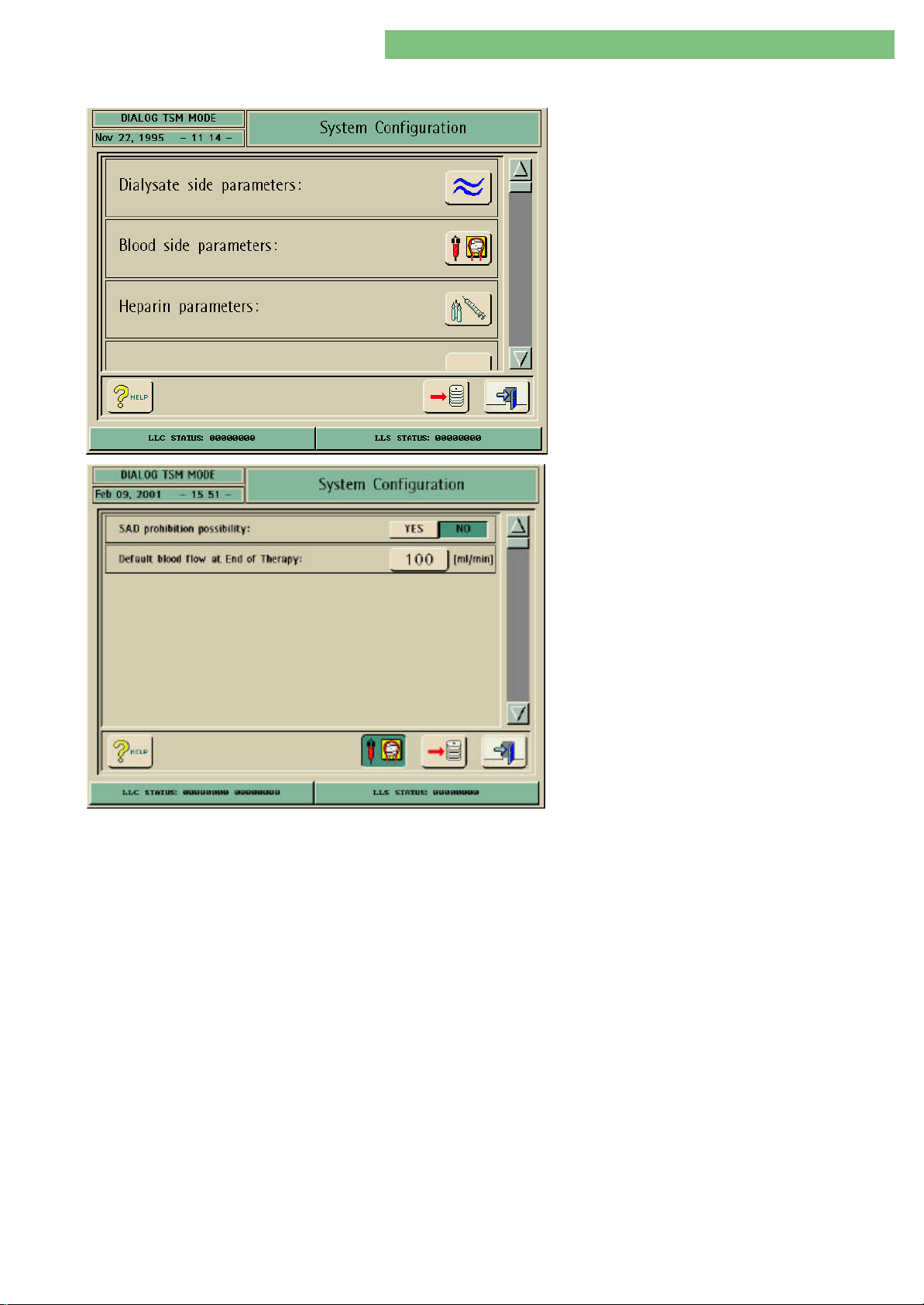
Temperature Measurement Unit
6. Click the Default Value window to change the
value [mS/cm].
• BIC without NaCl
• BIC with NaCl
7. Click the Acid icon to activate the selected acid.
The following menu is opened. You can enter
10 concentrate names and conversion factors
respectively. The selected concentrate name is
displayed in the Concentrate Name window.
8. Click the Default Value window if you want to
change the value [mS/cm].
You can set the current measurement unit of the
temperature.
Dialysate Flow
Dialysate Temperature
1. Activate the Dialysate Side Parameters menu
with the Dialysate Side Parameters icon.
2. Click the oC or F button to select and activate
the measurement unit.
You can preset the dialysate flow for therapy.
1. Click the ml/min button to set the dialysate flow.
You can set the dialysate temperature for therapy.
1. Click the oC button to set the dialysate temperature.
MT-MD-DE08C M.KAY
DialogAd_sm_Chapter 4-1_6-2004.doc/pdf <120304> ddmmyy
B. Braun Medizintechnologie GmbH
Page 28
4. TSM Service Program 6/2004 4 28
Dialog/Dialog Advanced
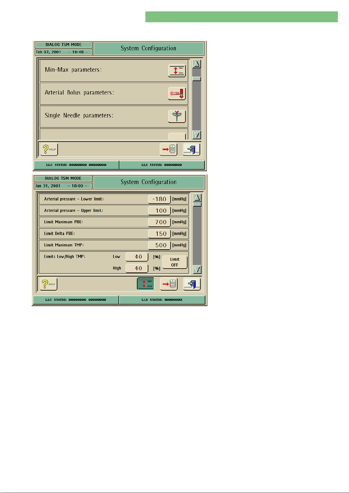
4.9.1.2 Blood Side Parameters
1. Activate the System Configuration menu with
the System Configuration button in menu
Treatment Support. Use the scroll bar until the
following menu appears.
2. Activate the Blood Side Parameters menu with
the Blood Side icon. The following menu is
opened.
SAD Prohibition Possibility
Default Blood Flow at End of Therapy
The following parameters can be set:
• SAD prohibition possibility
• Default Blood Flow at End of Therapy
You can activate the SAD prohibition with the YES button, during the
disconnection phase of the patient, i.e. the SAD alarm is suppressed during this
procedure and the blood pump can be started.
1. Click the YES or NO button to set the SAD prohibition possibility.
You can preselect the blood flow which will be preset at the end of a threapy.
1. Click the ml/min button to set the default blood flow at the end of a therapy.
MT-MD-DE08C M.KAY
DialogAd_sm_Chapter 4-1_6-2004.doc/pdf <120304> ddmmyy
B. Braun Medizintechnologie GmbH
Page 29
4. TSM Service Program 6/2004 4 29
Dialog/Dialog Advanced
4.9.1.3 Min-Max Parameters
1. Activate the System Configuration menu with
the System Configuration button in menu
Treatment Support. Use the scroll bar until the
following menu appears.
2. Activate the Min-Max Parameters menu with
the MIN-Max icon. The following menu is
opened.
Arterial Pressure - Lower Limit
Arterial Pressure - Upper Limit
Limit Maximum PBE
The following parameters can be set in the MinMax Parameters menu:
• Arterial Pressure - Lower Limit
• Arterial Pressure - Upper Limit
• Limit Maximum PBE
• Limit Delta PBE
• Limit Maximum TMP
• Limits Low/High TMP
You can set the lower limit for the arterial pressure in therapy.
Only for the LLC: the set range depends on the setting of the absolute lower limit
value of PA (menu: LLC Manual Calibration/2.12 PV Alarm Window, PA Absolute
Low Limit/PA Absolute Low Limit).
You can set the upper limit for the monitoring of the arterial pressure in therapy.
You can set the maximum limit for the monitoring of the PBE in therapy.
MT-MD-DE08C M.KAY
DialogAd_sm_Chapter 4-1_6-2004.doc/pdf <120304> ddmmyy
Limit Delta PBE
Limit Maximum TMP
Limits Low/High TMP
You can set the permissible changes for PBE during therapy.
You can set the upper limit for TMP for the monitoring in therapy.
The lower and upper limit can be set in % for TMP monitoring in therapy.
Limit OFF activated: Monitoring is not performed
Limit OFF deactivated: Monitoring is performed
B. Braun Medizintechnologie GmbH
Page 30
4. TSM Service Program 6/2004 4 30
Dialog/Dialog Advanced
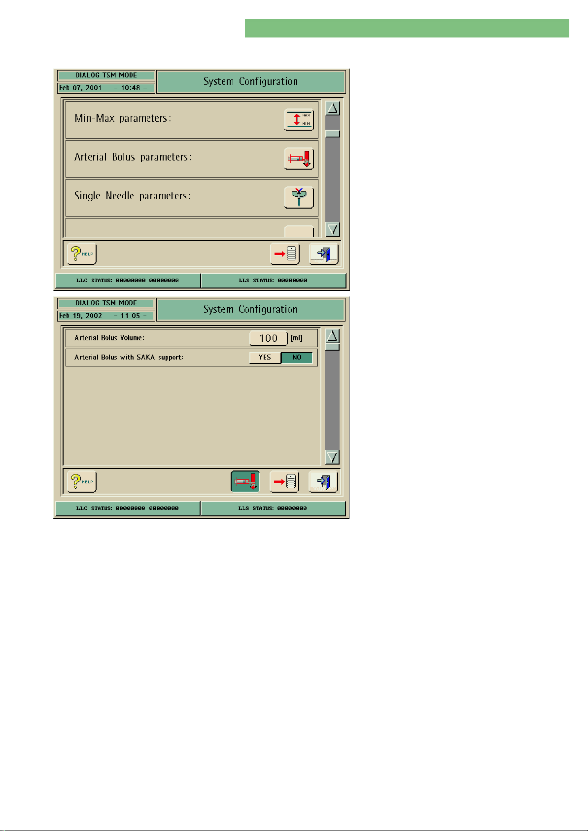
4.9.1.4 Arterial Bolus Parameters
1. Activate the System Configuration menu with
the System Configuration button in menu
Treatment Support. Use the scroll bar until the
following menu appears.
2. Activate the Arterial Bolus Parameters menu
with the Arterial Bolus icon. The following menu
is opened.
Arterial Bolus Volume
Arterial Bolus with SAKA Support
The following parameters can be set in the Arterial
Bolus Parameters menu:
• Arterial Bolus Volume
• Arterial Bolus with SAKA Support
The volume for an arterial bolus can be set.
The arterial tubing clamp SAKA can be used to support an arterial bolus in the
Arterial Bolus Parameters menu. Prerequisites are:
• Arterial tubing clamp SAKA present
• An arterial line system with infusion access is present between the SAKA and
blood pump
MT-MD-DE08C M.KAY
DialogAd_sm_Chapter 4-1_6-2004.doc/pdf <120304> ddmmyy
B. Braun Medizintechnologie GmbH
Page 31
4. TSM Service Program 6/2004 4 31
Dialog/Dialog Advanced
4.9.1.5 Single Needle Parameters
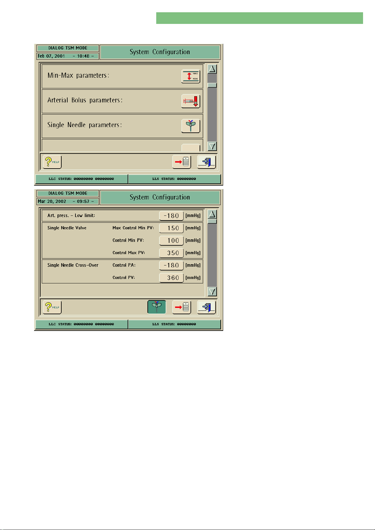
1. Activate the System Configuration menu with
the System Configuration button in menu
Treatment Support. Use the scroll bar until the
following menu appears.
2. Activate the Single Needle Parameters menu
with the Single Needle icon.
Arterial Pressure Low Limit
Single Needle Valve
The following parameters can be set:
• Arterial Pressure Low Limit
• Single Needle Valve (control pressures)
• Single Needle Cross-Over (control pressures)
You can set ther lower limit for the arterial pressure in therapy.
Only for LLC: The set range depends upon the setting of the absolute lower limit
value of PA (menu: LLC Manual Calibration/2.12 PV Alarm Window, PA Absolute
Low Limit)
The maximum lower venous control pressure can be set for the Single Needle
Valve option in the Single Needle menu.
Maximum Control Minimum PV
For safety reasons it is necessary to limit the maximum value for the lower
venous controll pressure for the SN valve. The maximun setting is 150 mmHg
(default setting).
If the SAKV currentless closed option is present (AAMI standard) the value can be
set higher.
Furthermore the control pressure PV can be set. Thereby the blood pump is
started/stopped and the venous tubing clamp SAKV is opened/closed.
Single Needle Cross-Over
MT-MD-DE08C M.KAY
DialogAd_sm_Chapter 4-1_6-2004.doc/pdf <120304> ddmmyy
The control pressures for PA and PV can be set for single needle cross-over.
B. Braun Medizintechnologie GmbH
Page 32
4. TSM Service Program 6/2004 4 32
Dialog/Dialog Advanced
4.9.1.6 Heparin Parameters
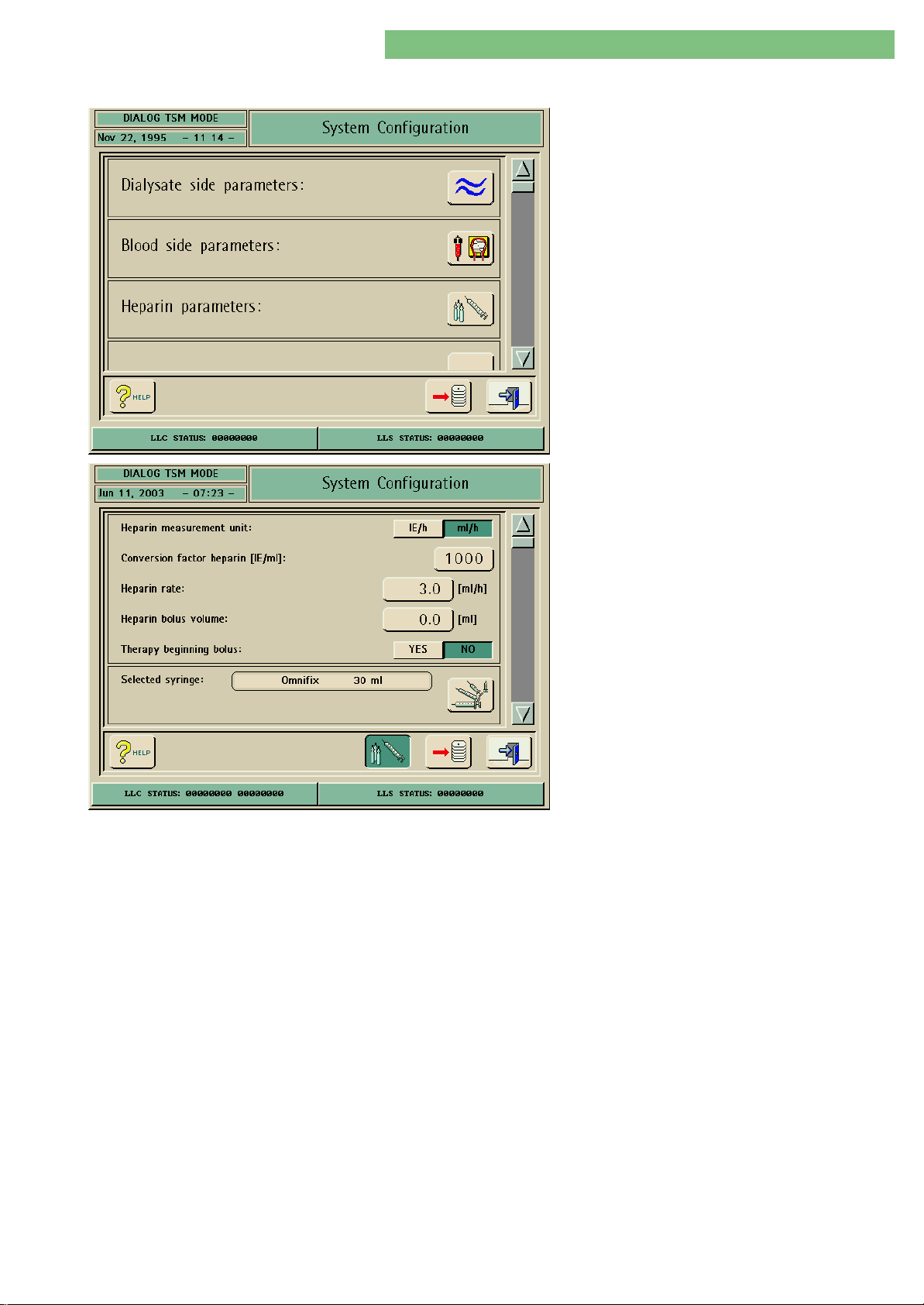
You can set the parameters in the Heparin
Parameters menu and select a syringe type.
1. Activate the System Configuration menu with
the System Configuration button in menu
Treatment Support. The following menu is
opened.
2. Activate the Heparin Parameters menu with the
Heparin Parameters icon. The following menu is
opened.
Heparin Measurement Unit
Conversion Factor Heparin [IE/ml]
Heparin Rate
The following parameters can be set:
• Heparin measurement unit
• Conversion factor heparin [IE/ml]
• Heparin rate
• Heparin bolus volume
• Therapy beginning bolus
• Selected syringe
The measurement unit [IE/H] or [ml/h] can be selected for heparin.
You can set the conversion factor ([IE/ML] dependimg on the mixing ratio, if the
amount of heparin should be displayed in international units (IE). The conversion
factor describes the quantity of IE in 1 ml solution, e.g. 1000 IE represent in 1 ml
solution 1000 IE heparin.
The heparin rate can be set to [IE/h] or [ml/h], depending on the selected uint.
MT-MD-DE08C M.KAY
DialogAd_sm_Chapter 4-1_6-2004.doc/pdf <120304> ddmmyy
Heparin Bolus Volume
Therapy Beginning Bolus
You can select the bolus volume for the heparin bolus.
An automatic bolus can be administered at the bebinning of a therapy. The bolus
is administered by the red sensor RDA as soon as the blood pump detects blood.
B. Braun Medizintechnologie GmbH
Page 33
33
Dialog/Dialog Advanced
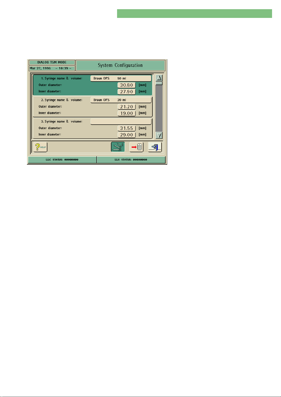
Selected Syringe
4. TSM Service Program 6/2004 4 -
The selected syringe type is used in therapy.
Heparin Pump Comfort
Heparin Pump Compact
You can set the syringe name and the outer and inner diameter of the syringe.
You can set the syringe name and the inner diameter of the syringe.
1. Activate the Selected Syringe menu with the
Selected Syringe icon. The following menu is
opened.
MT-MD-DE08C M.KAY
DialogAd_sm_Chapter 4-1_6-2004.doc/pdf <120304> ddmmyy
B. Braun Medizintechnologie GmbH
Page 34
4. TSM Service Program 6/2004 4 34
Dialog/Dialog Advanced
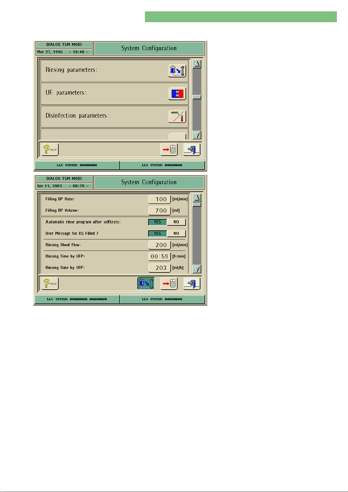
4.9.1.7 Rinsing Parameters
The Rinsing Parameters can be set in the Rinsing
Parameters menu.
1. Activate the System Configuration menu with
the System Configuration button in menu
Treatment Support. The following menu is
opened and displayed (scroll with scroll bar).
2. Activate the Rinsing Parameters menu with the
Rinsing Parameters icon. The following menu is
displayed.
Filling BP Rate
Filling BP Volume
The following parameters can be set:
• Filling BP rate
• Filling BP volume
• Automatic rinse program after selftests
• User message for BS filled?
• Rinsing bloood flow
• Rinsing time by UFP
• Rinsing rate by UFP
• Rinsing volume by UFP
• Rinsing time by BPA or BPV
• Rinsing rate by BPA or BPV
• Rinsing volume by BPA or BPV
• Blood Flow for connecting patient
You can set the BP rate to fill the blood line system (BS) for all rinsing modes.
You can set the filling/rinsing volume for the A/V system.
With Rinsing Out of Machine
The filling of the dialyser is started after the filling BP volume is reached (e.g. 300
ml).
With Bag Rinsing
The blood pump BPA is stopped after the filling BP volume is reached (e.g. 300
ml). This allows the changing from two bags to one bag.
Automatic Rinse Program after Selftests
MT-MD-DE08C M.KAY
DialogAd_sm_Chapter 4-1_6-2004.doc/pdf <120304> ddmmyy
If YES is Activated
Thr rinsing is automatically performed directly after the BS selftests.
If NO is Activated
The rinsing must be started manually after the BS selftests.
B. Braun Medizintechnologie GmbH
Page 35

4. TSM Service Program 6/2004 4 35
Dialog/Dialog Advanced
User Message for BS Filled?
Rinsing Bloood Flow
If YES is Activated
The following user message is displayed after rinsing out of the machine:
Is the blood system filled with NaCl solution and rinsed?
All levels correctly set?
The BS system is filled until the key is pressed and the filling BP volume is
completed. Thus the level can be set. Then the dialyser can be turned to fill the
DF side.
If NO is Activated
The filling of the dialyser is automatically started after the Filling BP Volume is
finished.
You can set the blood flow for rinsing. After the selftests BPA delivers a
longitudinal flow during rinsing. This depends on the rinsing mode.
Longitudinal rinsing (along the dialyser):
• Blood side inlet/outlet
• Water side inlet/outlet
Cross rinsing (through the dialyser membrane):
• Blood side to water side
NoteNote
Interdependencies when changing parameters:
ChangeChange Automatic Adaptation fromAutomatic Adaptation from
Rinsing Time Rate
Rate Rinsing Time
Rinsing Volume Rate
Rinsing Time by UFP
Rinsing Rate by UFP
Rinsing Volume by UFP
Rinsing Time by BPA/BPV
Rinsing Rate by BPA/BPV
Rinsing Volume by BPA/BPV
Blood Flow for Connecting Patient
You can set the rinsing time (for bag rinsing without substitution line (s-online)).
Thus rinsing via the dialyser membrane is possible. After the termination of the
rinsing time, rinsing is performed with min. UF.
You can set the rinsing rate for the UFP to reach the Rinsing Volume by UFP. The
Rinsing Time by UFP is automatically recalculated.
You can set the rinsing volume (via the dialyser membrane) for the Rinsing Time
by UFP. The Rinsing Rate by UFP is automatically recalculated.
The rinsing time for Rinsing Volume by BPA or BPV is set. BPA/BPV generates the
rinsing flow via the dialyser membrane for bag rinsing with connected s-online
and rinsing out of the machine.
The rinsing rate is set for Rinsing Volume by BPA or BPV .
The rinsing volume (via the dialyser membrane) is set for Rinsing Time by BPA or
BPV.
You can set the blood flow for connecting the patient (in therapy). The blood
pump BPA is started with this rate when the therapy is started.
MT-MD-DE08C M.KAY
DialogAd_sm_Chapter 4-1_6-2004.doc/pdf <120304> ddmmyy
B. Braun Medizintechnologie GmbH
Page 36
4. TSM Service Program 6/2004 4 36
Dialog/Dialog Advanced
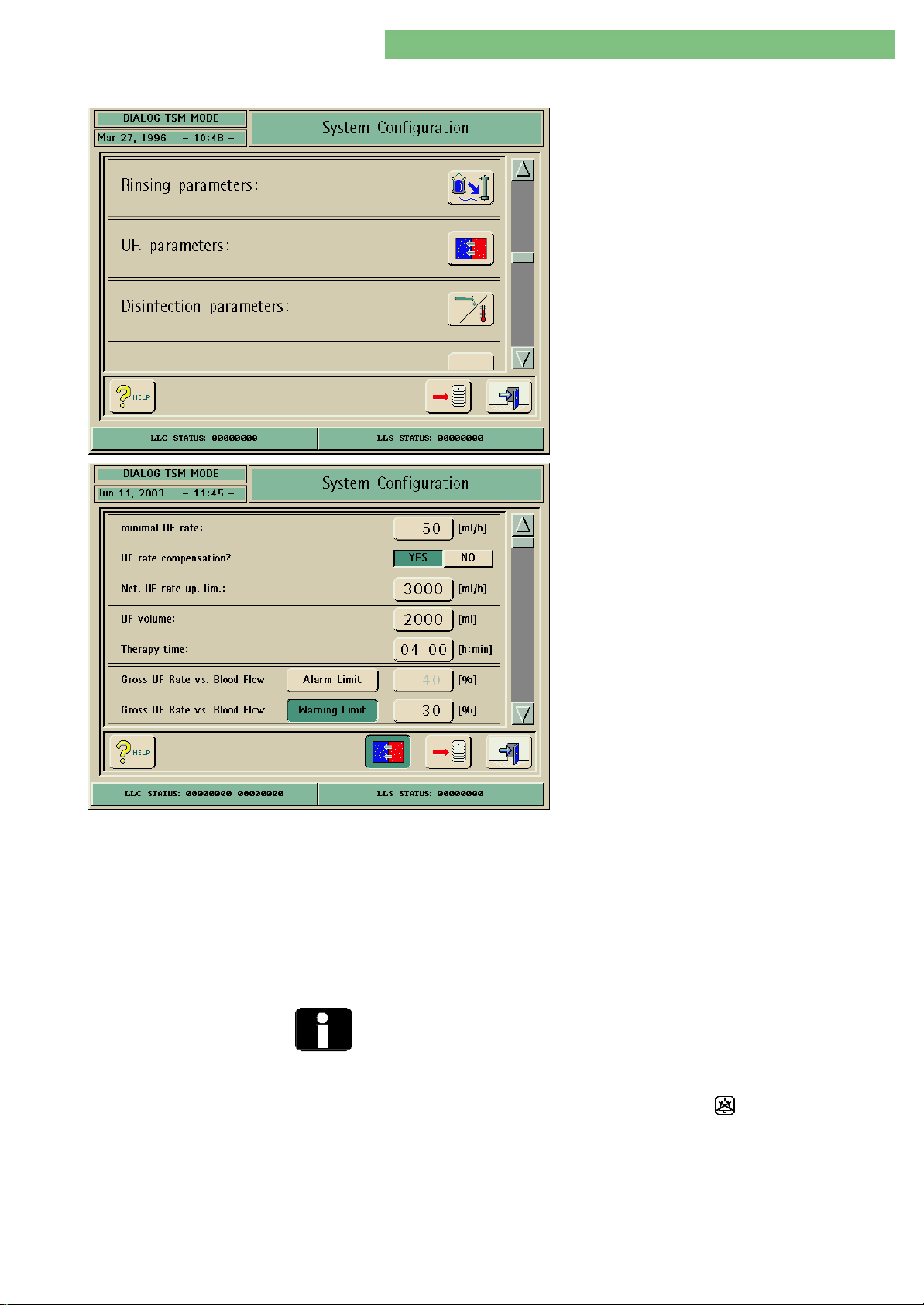
4.9.1.8 UF Parameters
The dialysate fluid parameters can be set in the UF
Parameters menu.
1. Activate the System Configuration menu with
the System Configuration button in menu
Treatment Support. The following menu is
opened and displayed (scroll with scroll bar).
2. Activate the UF Parameters menu with the UF
Parameters icon. The following menu is opened.
The following parameters can be set:
Minimal UF-Rate
UF Rate Compensation?
Net UF Rate Upper Limit
UF Volume
Therapy Time
• Minimal UF rate
• UF rate compensation?
• Net UF rate upper limit
• UF volume
• Therapy time
• Gross UF rate vs. blood flow - alarm limit
• Gross UF rate vs. blood flow - warning limit
• UF profile editor
You can set the minimal UF rate.
If YES is Activated
If the Minimal UF Rate is active the Uf rate is recalculated to reach the required
UF volume.
You can set the upper limit of the net UF rate.
You can set the UF volume.
You can set the therapy time.
Gross UF Rate vs. Blood Flow -
MT-MD-DE08C M.KAY
DialogAd_sm_Chapter 4-1_6-2004.doc/pdf <120304> ddmmyy
Alarm Limit
There is no limit alarms for HDF machines in predilution.
You can set and activate an alarm limit, i.e. an alarm (red) is activated if the limit
is reached. The alarm limit can only be changed if the warning limit was changed
in advance. The alarm can be acknowledged with the key.
Setting RangeSetting Range
The alarm limit can not be set lower than the warning limit (even if the warning
limit is deactivated).
B. Braun Medizintechnologie GmbH
Page 37

4. TSM Service Program 6/2004 4 37
Dialog/Dialog Advanced
Gross UF Rate vs. Blood Flow -
Warning Limit
Alarm Limit/Warning Limit Alarm Limit Warning Limit
You can set and activate a warning limit, i.e. a warning (yellow) is activated if the
limit is reached.
Setting RangeSetting Range
The alarm limit can not be set lower than the warning limit (even if the warning
limit is deactivated).
deactivated deactivated No alarm/no warning in therapy
deactivated activated Warning in therapy if limit is
activated deactivated Alarm in therapy if limit is exceeded
activated activated Alarm and warning in therapy if limit
exceeded
is exceeded
MT-MD-DE08C M.KAY
DialogAd_sm_Chapter 4-1_6-2004.doc/pdf <120304> ddmmyy
B. Braun Medizintechnologie GmbH
Page 38
4. TSM Service Program 6/2004 4 38
Dialog/Dialog Advanced
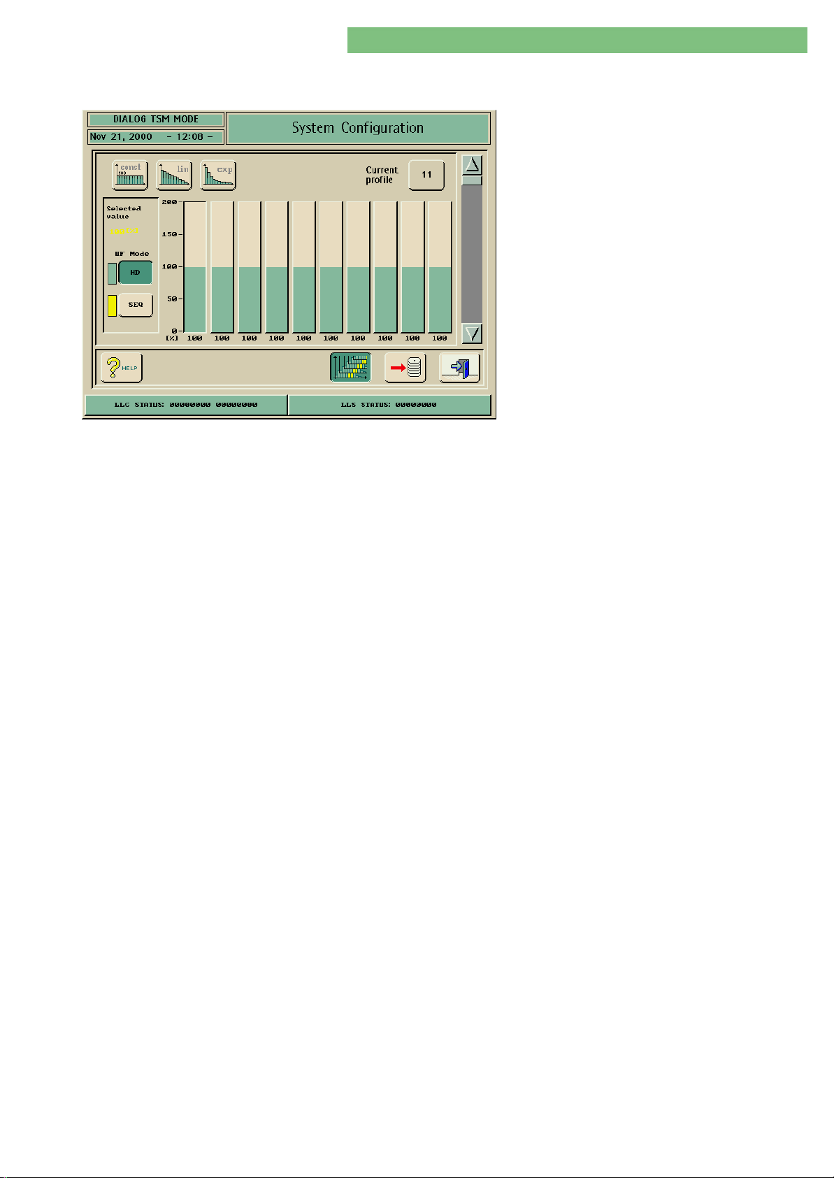
UF Profile Editor
The UF profile can be edited in the UF Profile Editor. Editing can be performed in
the therapy mode and in the TSM service program.
CONST (Constant)
If this button is activated all intervals of the profile
are set to 100%.
LIN (Linear)
If this button is activated only the first interval can
be set. A linear adaptation is calculated for the
remaining process.
EXP (Exponential)
If this button is activated only the first interval can
be set. An exponential adaptation is calculated for
the remaining process.
NoteNote
If both the LIN and EXP buttons are not activated the response of the graph can
be selected individually. If an interval is changed the remaining intervals are
adapted accordingly. The last interval can not be modified, because this setting is
calculated from the previous interval settings.
Current Profile No.
The profile selected with this button is displayed and can be modified. Additionally
to 10 standard profiles 20 further profiles can be activated, displayed and
modified.
Profile No. 0
This is a constant 100% profile.
Profile No. 1 to 9
These profiles are pre-defined.
Profile No. 10
A profile which was edited in therapy.
Profile No. 11 to 30
These profiles can be edited in the TSM service program and stored under a
number.
UF Mode HD
The UF process of the activated interval is set to HD with the HD button.
UF Mode Sequential SEQ
The UF process of the activated interval is set to sequential with the SEQ button.
MT-MD-DE08C M.KAY
DialogAd_sm_Chapter 4-1_6-2004.doc/pdf <120304> ddmmyy
B. Braun Medizintechnologie GmbH
Page 39
4. TSM Service Program 6/2004 4 39
Dialog/Dialog Advanced
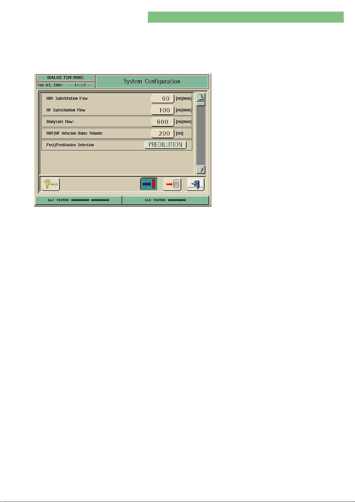
4.9.1.9 HDF/HF Parameters
1. Activate the System Configuration menu with
the System Configuration button in menu
Treatment Support. Use the scroll bar until the
following menu appears.
2. Activate the Single Needle Parameters menu
with the Single Needle icon. The following menu
is opened.
The following parameters can be set.
• HDF/HF substitution flow
• Dialysate flow
• HDF/HF infusion bolus volume
• Post/Predilution Selection
HDF/HF Substitution Flow
Dialysate Flow
HDF/HF Infusion Bolus Volume
Post/Predilution Selection
The HDF/HF substitution flow can be set.
The dialysate flow can be set.
The HDF/HF infusion bolus volume can be set.
You can set predilution for a HDF/HF therapy by activating the Predilution button.
MT-MD-DE08C M.KAY
DialogAd_sm_Chapter 4-1_6-2004.doc/pdf <120304> ddmmyy
B. Braun Medizintechnologie GmbH
Page 40
4. TSM Service Program 6/2004 4 40
Dialog/Dialog Advanced
4.9.1.10 Disinfection Parameters
Disinfection after servicing in TSM
Before disinfection: rinse the machine to remove residual
dialysate or concentrate in the system.
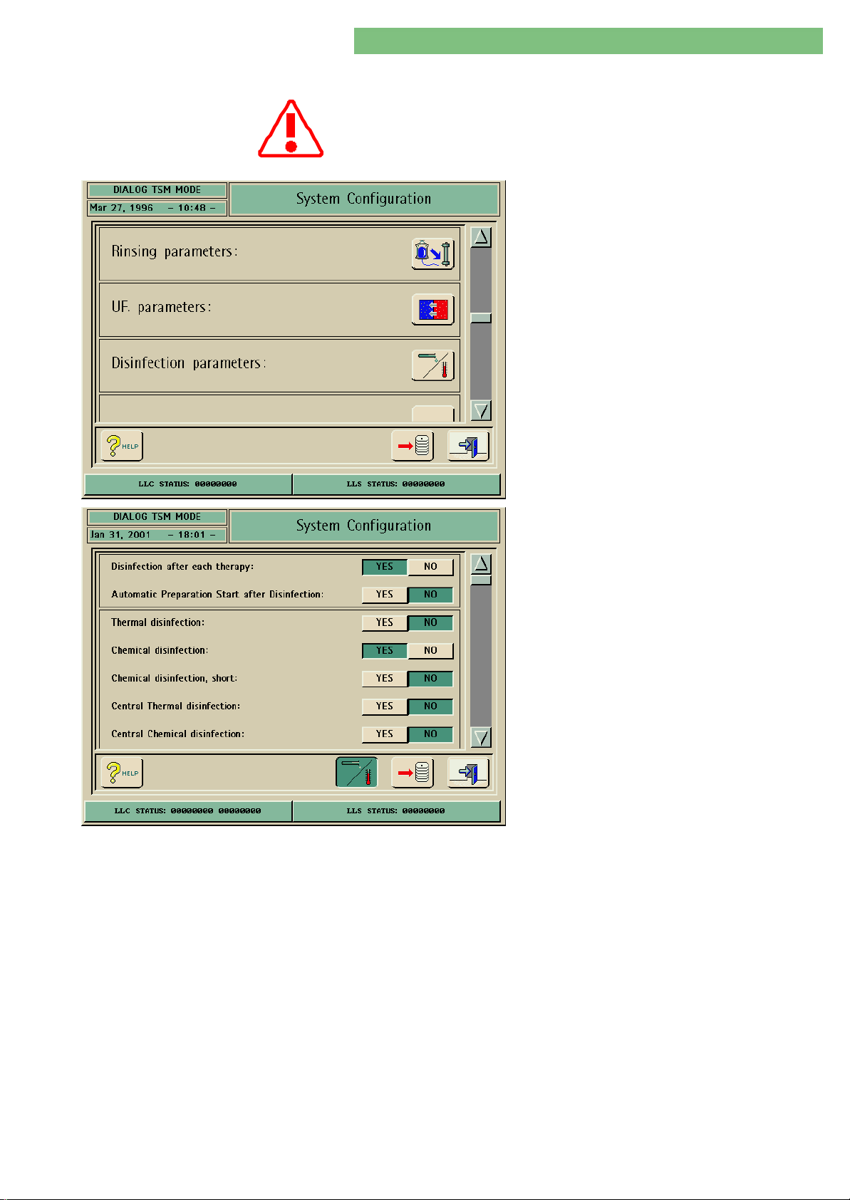
The disinfection parameters can be set in the
Disinfection Parameters menu.
1. Activate the System Configuration menu with
the System Configuration button in menu
Treatment Support. The following menu is
opened and displayed (scroll with scroll bar).
2. Activate the Disinfection menu with the
Disinfection Parameters icon. The following
menu is displayed.
3. Scroll the menu with the scroll bar.
The following parameters can be set:
• Disinfection after each therapy
• Automatic Preparation Start after Disinfection
• Thermal Disinfection
• Chemical Disinfection
• Chemical Disinfection, Short
• Central Thermal Disinfection
• Central Chemical Disinfection
• Rinsing
• Auto Switch-On with Rinsing (No Weekly
Schedule)
• Switch-On Time
• Auto Switch-On by Weekly Schedule
• Weekly Schedule
• Start on Sunday/Start on Monday
• Maximum Out of Action Time (Day/Hour/
Minutes)
• Disinfection Configuration Data (Central Thermal,
Central Chemical, Rinsing)
Disinfection after each Therapy
Automatic Preparation Start
MT-MD-DE08C M.KAY
DialogAd_sm_Chapter 4-1_6-2004.doc/pdf <120304> ddmmyy
after Disinfection
If the YES button is activated a disinfection must be performed after every
therapy.
YES
After disinfection and rinsing the Preparation and the selftests are started.
NO
After disinfection and rinsing the disinfection method is terminated.
B. Braun Medizintechnologie GmbH
Page 41
41
Dialog/Dialog Advanced
Thermal Disinfection
4. TSM Service Program 6/2004 4 -
You can enable the thermal disinfection with the YES button in the disinfection
program or disable with the NO button. If you select the NO button the thermal
disinfection icon is not displayed in the disinfection program.
Chemical Disinfection
Short Chemical Disinfection
Central Thermal Disinfection
Central Chemical Disinfection
Rinsing
You can enable the chemical disinfection with the YES button in the disinfection
program or disable with the NO button. If you select the NO button the chemical
disinfection icon is not displayed in the disinfection program.
You can enable the short chemical disinfection with the YES button in the
disinfection program or disable with the NO button. If you select the NO button
the short chemical disinfection icon is not displayed in the disinfection program.
The inlet feed-line and the machine are disinfected with hot water, if the central
facility loop-line is also disinfected with hot water (> 85oC).
The inlet feed-lines are disinfected with chemical disinfectants, if the central
facility loop-line is also disinfected with chemical disinfectants.
Rinsing of disinfectant residues: e.g. a disinfection was performed in the evening
and the residues are rinsed in the morning.
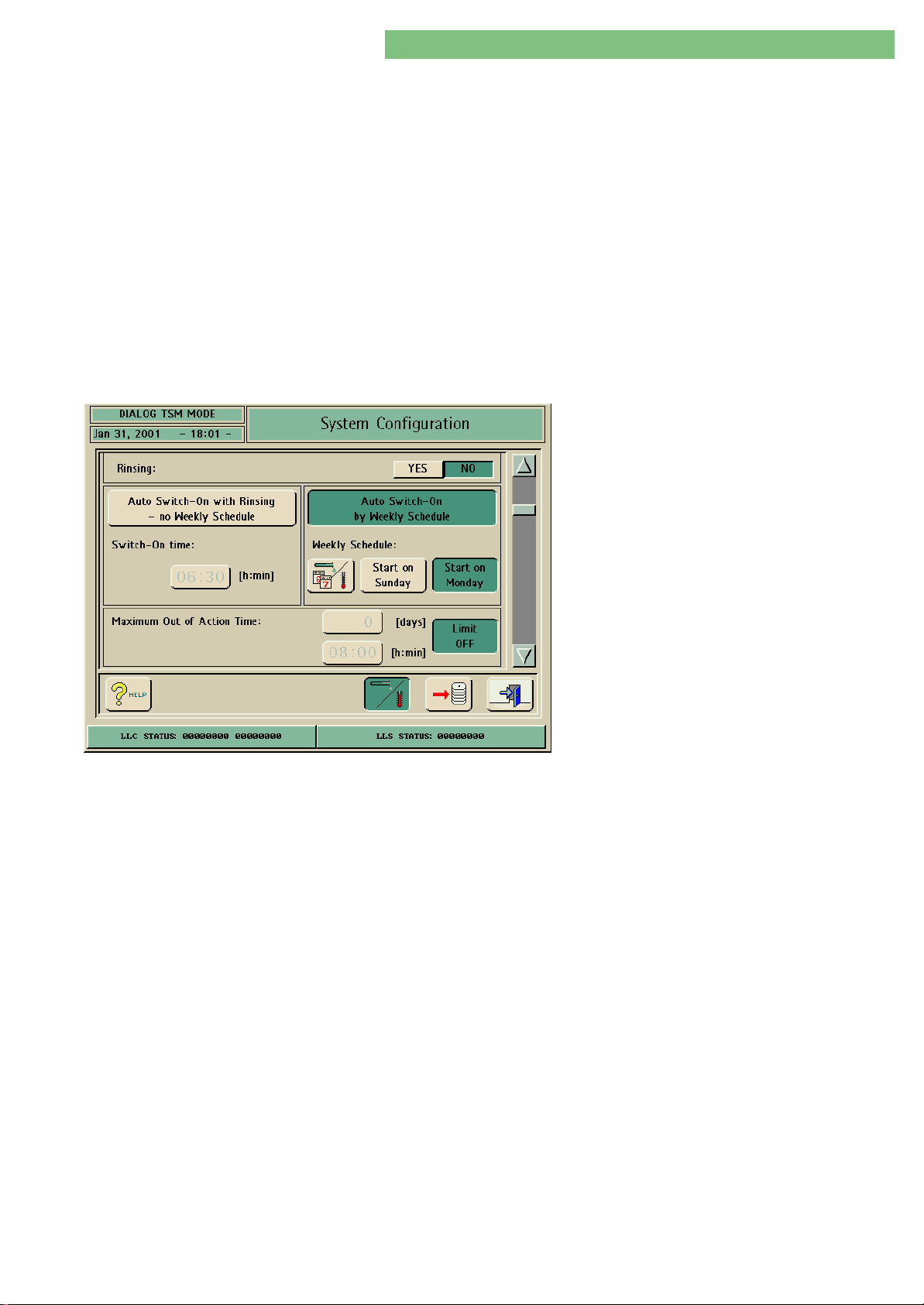
The parameters for the switch-on and the weekly
schedule can be set in the menu Auto Switch-On
with Rinsing (No Weekly Schedule) and Auto
Switch-On (by Weekly Schedule). The buttons are
interlocked.
Auto Switch-On with Rinsing
(No Weekly Schedule)
Weekly Schedule
Start on Sunday/Start on Monday
Maximum Out of Action Time
The machine is rinsed after the preselected switch-on time. The button is only
enabled if the function is selected.
The parameters for the weekly schedule can be set with the Weekly Schedule.
The table for the weekly schedule can either start with Sunday or Monday.
Limit OFF
The function is activated if the Limit OFF button is not pressed.
The Limit OFF button is activated in the default setting, the parameter buttons are
disabled, i.e. parameter values can not be set.
MT-MD-DE08C M.KAY
DialogAd_sm_Chapter 4-1_6-2004.doc/pdf <120304> ddmmyy
B. Braun Medizintechnologie GmbH
Page 42
4. TSM Service Program 6/2004 4 42
Dialog/Dialog Advanced
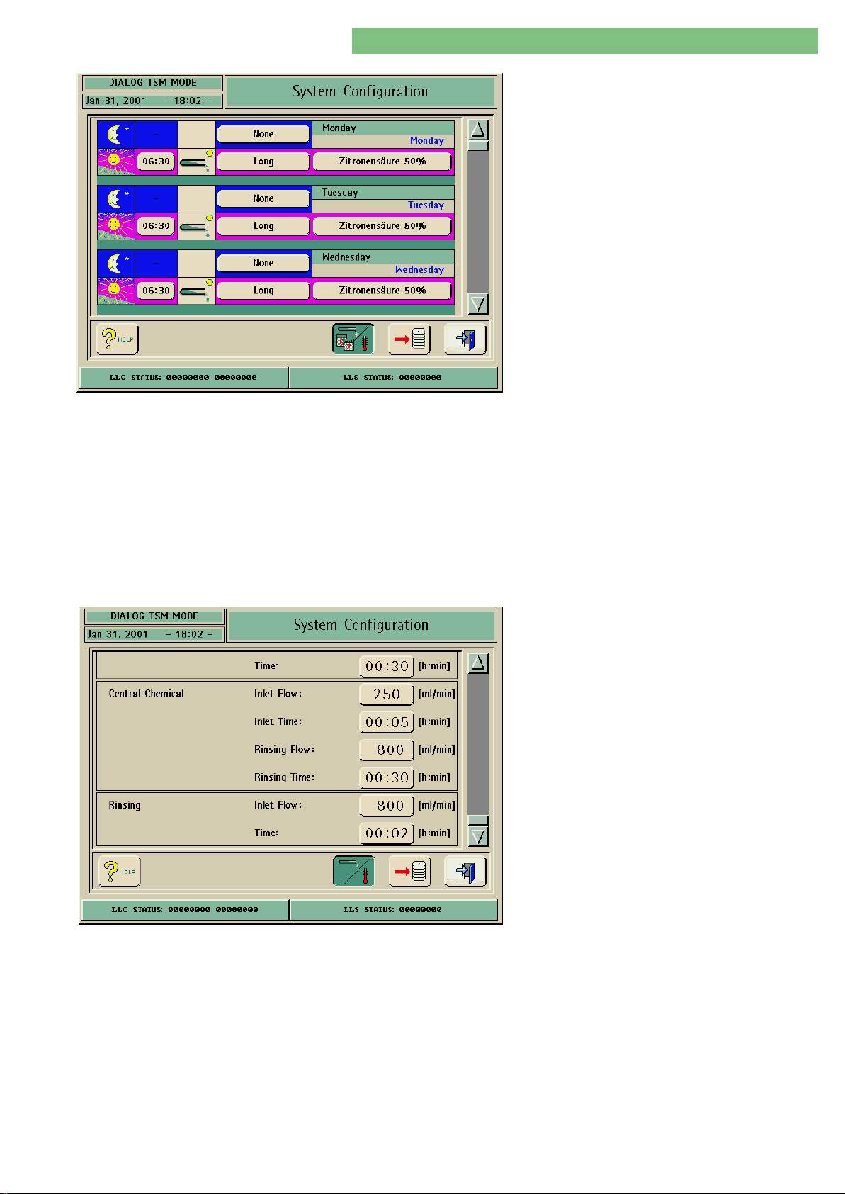
The parameters for the weekly schedule can be set
in the Weekly Schedule menu.
The table can also be modified by the user in the
therapy/disinfection mode.
Auto Switch-On by Weekly Schedule
Disinfection Configuration Data (Central
Thermal, Central Chemical, Rinsing)
The selected disinfection method is performed according to the preselected
Weekday and Time parameters:
• Monday, Tuesday ....... Sunday
• Night (Moon Symbol), Dialog switches off after disinfection is completed
• Day (Sun Symbol), Dialog does not switch off and remains in Rinsing
• Switch-On Time
• Disinfection Method
• Disinfectants
The parameters for the water inlet system can be set in the menu Disinfection
Configuration Data (Central Thermal, Central Chemical, Rinsing) .
Central Thermal:
• Inlet Flow
• Time
Central Chemical:
• Inlet Flow
• Inlet Time
• Rinsing Flow
• Rinsing Time
Rinsing:
• Inlet Flow
• Time
MT-MD-DE08C M.KAY
DialogAd_sm_Chapter 4-1_6-2004.doc/pdf <120304> ddmmyy
B. Braun Medizintechnologie GmbH
Page 43
4. TSM Service Program 6/2004 4 43
Dialog/Dialog Advanced
4.9.1.11 Filter Parameters
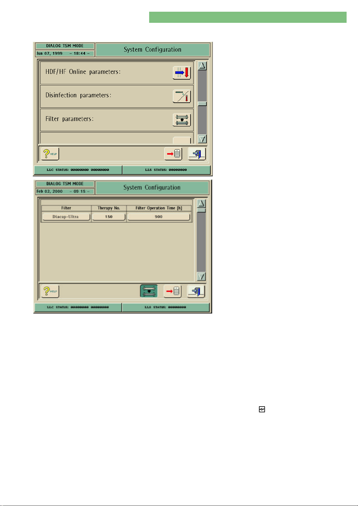
1. Activate the System Configuration menu with
the System Configuration button in menu
Treatment Support. Use the scroll bar until the
following menu appears.
2. Activate the Filter Parameters menu with the
Filter icon.
The following parameters can be set for HDF online
and pyrogen filter:
Filter
Therapy Number
• Filter type, e.g. Diacap-Ultra
• Number of therapies (therapy no.)
• Filter operating hour counter (operating time) [h]
The filter type can be typed, e.g. Diacap-Ultra.
The number of therapies can be set for the DF/HDF filters.
The following messages are displayed before Preparation, after the life-time data
for therapy numbers/filter operation time is expired (one of the first three lines
are selected/displayed depending on the filter/s which is/are expired):
<Check the DF Filter!> or
<Check the HDF Filter!> or
<Check the DF and HDF Filter!> or
<Check the life-time data on the service screen!>
<Do you want to continue with an expired filter?>
MT-MD-DE08C M.KAY
DialogAd_sm_Chapter 4-1_6-2004.doc/pdf <120304> ddmmyy
Filter Operation Time [h]
The message must be acknowledged with the key.
The operating hours can be set for the intended operation time of the DF/HDF
filters. The operating hour counter is active when DF Preparation is active.
B. Braun Medizintechnologie GmbH
Page 44
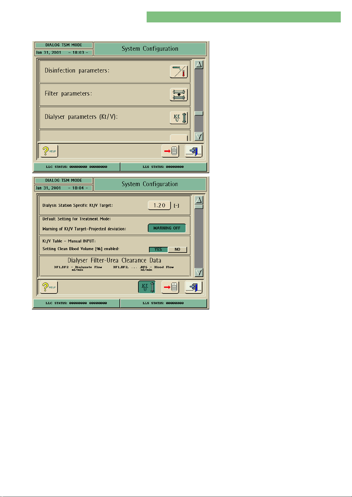
4. TSM Service Program 6/2004 4 44
Dialog/Dialog Advanced
4.9.1.12 Dialyser Parameters (Kt/V)
1. Activate the System Configuration menu with
the System Configuration button in menu
Treatment Support. Use the scroll bar until the
following menu appears.
2. Activate the Dialyser Parameters (Kt/V) menu
with the Dialyser icon.
The following parameters can be set.
Dialysis Station Specific Kt/V Target
Default Setting for Treatment Mode:
Warning of Kt/V Target Projected Deviation
Kt/V Table - Manual INPUT:
Setting Clean Blood Volume [%] Enabled
Dialyser Filter Urea Clearance Data
• Dialysis Station Specific Kt/V Target
• Default Setting for Treatment Mode Warning of
Kt/V Target Projected Deviation
• Kt/V Table - Manual INPUT Setting Clean Blood
Volume [%] Enabled
• Dialyser Filter Urea Clearance Data
The target value is the Kt/V value at the end of a therapy. The target is set by the
user.
If the calculated Kt/V from the set parameters is smaller than the set target value
a message is activated.
YES = Activated
The ratio can be edited subsequently in therapy for adaptation to the calculated
Kt/V value.
The Kt/V is approximately calculated via the Dialyser Filter Urea Clearance Data
for the selected dialyser (see table, use scroll bar to see table).
MT-MD-DE08C M.KAY
DialogAd_sm_Chapter 4-1_6-2004.doc/pdf <120304> ddmmyy
B. Braun Medizintechnologie GmbH
Page 45
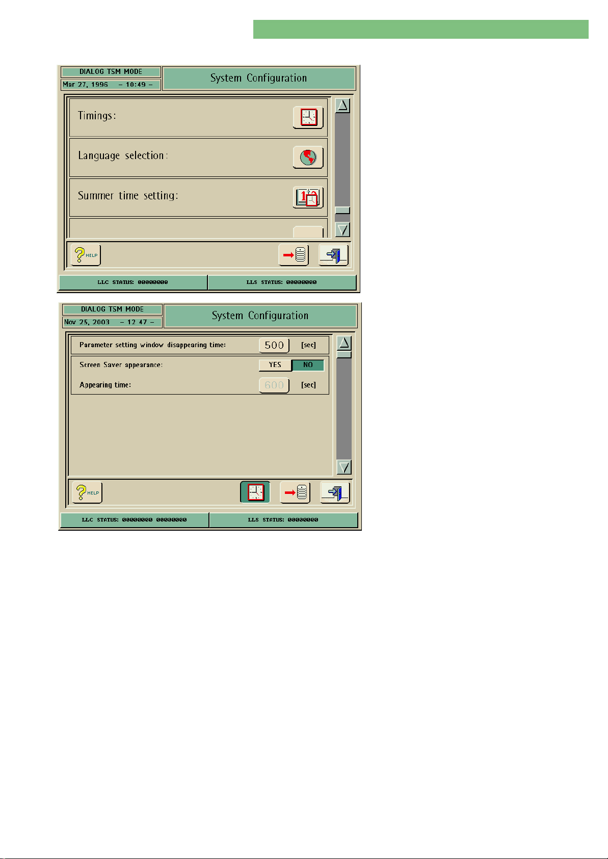
4. TSM Service Program 6/2004 4 45
Dialog/Dialog Advanced
4.9.1.13 Timings
The time parameters can be set in the Timings
menu.
1. Activate the System Configuration menu with
the System Configuration button in menu
Treatment Support. The following menu is
opened and displayed (scroll with scroll bar):
2. Activate the Timings menu with the Timings
icon. The following menu is displayed.
Parameter Setting Window
Disappearing Time
Screen Saver Appearance
The following parameters can be set:
• Parameter setting window disappearing time
• Screen saver appearance
• Appearing time
You can set the automatic disappearing time for the Parameter Setting Window
(lower screen in therapy).
You can activate a screen saver with the YES button. The actual image on the
screen is then replaced by the screen saver, according to the preset time. The
original image appears in case of an alarm or if the screen is touched. The
following screen savers are activated:
Therapy selection: B.Braun logo, date, time
Preparation: B.Braun logo, time, status line
Therapy and end of therapy: Time cake, remaining time, status line
Disinfection: Time cake, disinfection mode, phase
MT-MD-DE08C M.KAY
DialogAd_sm_Chapter 4-1_6-2004.doc/pdf <120304> ddmmyy
Appearing Time
You can set the appearance time of the Screen Saver.
B. Braun Medizintechnologie GmbH
Page 46
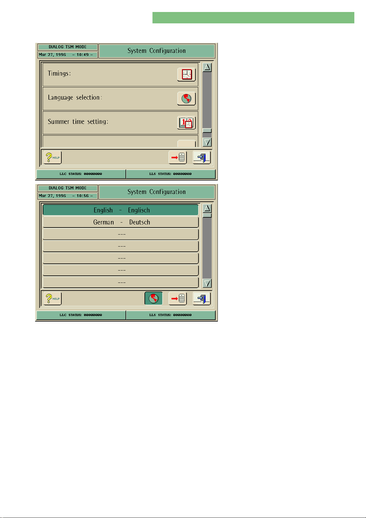
4. TSM Service Program 6/2004 4 46
Dialog/Dialog Advanced
4.9.1.14 Language Selection
A language can be selected in the Language
Selection menu.
1. Activate the System Configuration menu with
the System Configuration button in menu
Treatment Support. The following menu is
opened and displayed (scroll with scroll bar).
2. Activate the Language Selection menu with the
Language Selection icon. If necessary use the
scroll bar to move the menu down. Select the
English or German language or an additional
language which is available. The following
menu is displayed (or if available additional
language).
If English is selected the therapy and TSM language
is English. If German is selected the therapy and
TSM language is German. If an additional language
is selected this language is used in therapy. The
TSM language is English.
MT-MD-DE08C M.KAY
DialogAd_sm_Chapter 4-1_6-2004.doc/pdf <120304> ddmmyy
B. Braun Medizintechnologie GmbH
Page 47
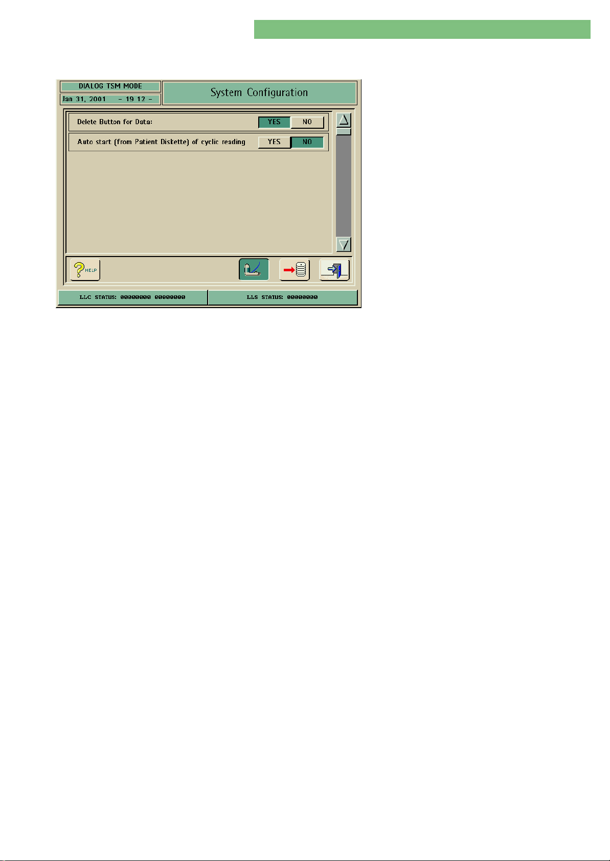
4. TSM Service Program 6/2004 4 47
Dialog/Dialog Advanced
4.9.1.15 Automatic Blood Pressure
Measurement ABPM
Delete Button Data
The ABPM parameters can be set in the ABPM
menu.
1. Activate the System Configuration menu with
the System Configuration button in menu
Treatment Support. The following menu is
opened and displayed.
The following parameters can be set:
• Delete Button Data
• Auto Start (from Patient Diskette) of Cyclic
Reading
YES = Activated
In therapy a delete button is displayed in the ABPM menu. The measurement data
can be deleted in the table.
Auto Start (from Patient Diskette)
of Cyclic Reading
NO = Deactivated
The measurement data is saved in the table until the end of therapy and can not
be deleted.
NO
The cyclic blood pressure measurement must always be selected manually.
YES
If the cyclic blood pressure measurement is on the patient diskette ABPM is
automatically activated at the beginning of a new therapy.
MT-MD-DE08C M.KAY
DialogAd_sm_Chapter 4-1_6-2004.doc/pdf <120304> ddmmyy
B. Braun Medizintechnologie GmbH
Page 48
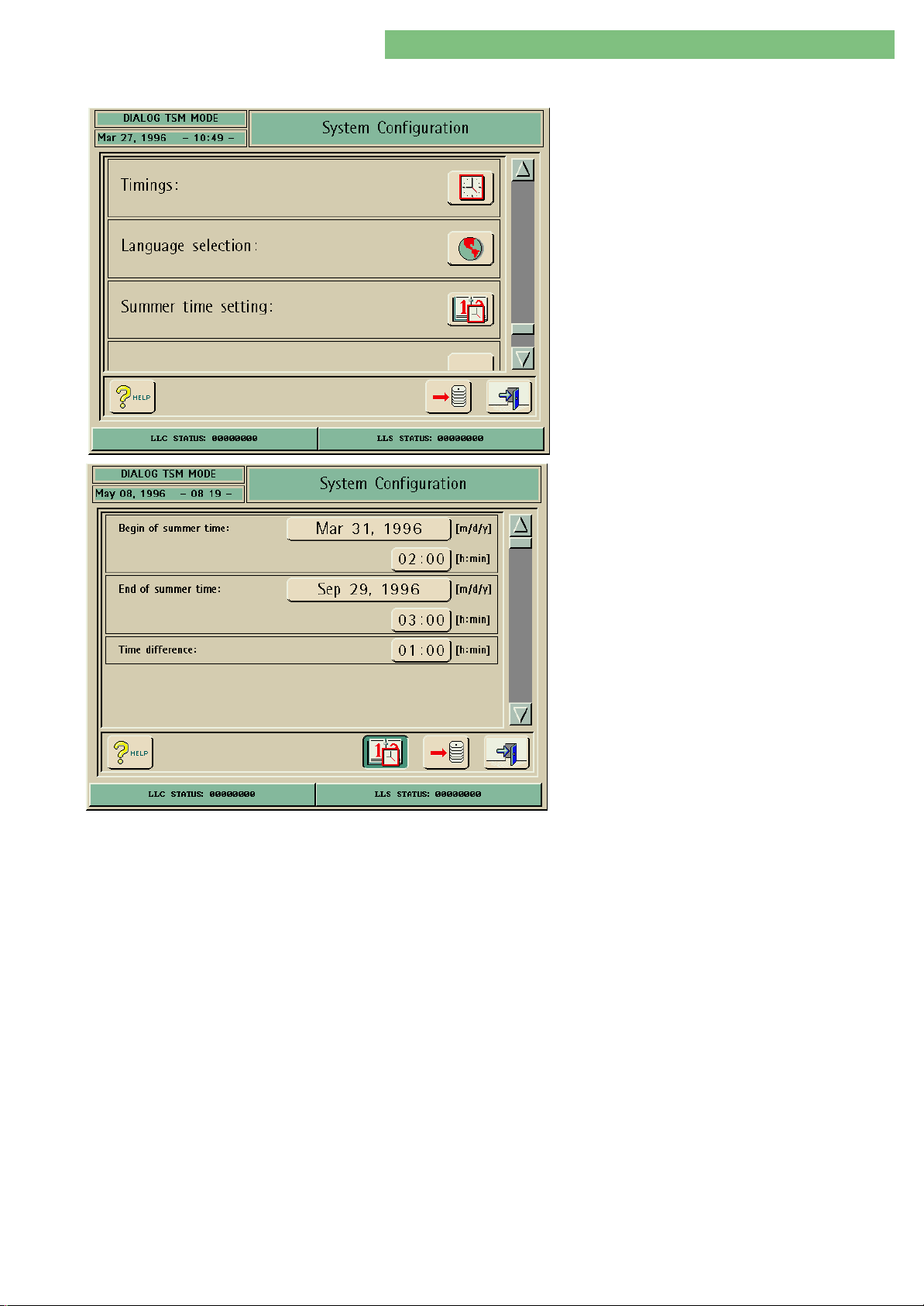
4. TSM Service Program 6/2004 4 48
Dialog/Dialog Advanced
4.9.1.16 Summer Time Setting
The Summer Time Parameters can be set in the
Summer Time Setting menu.
1. Activate the System Configuration menu with
the System Configuration button in menu
Treatment Support. The following menu is
opened and displayed (scroll with scroll bar).
2. Activate the Summer Time Setting menu with
the Summer Time Setting icon. The following
menu is displayed.
Begin of Summer Time
End of Summer Time
Time Difference
The following parameters can be set:
• Begin of summer time
• End of summer time
• Time difference
If necessary you can set the start of the summer time (date and hour).
If necessary you can set the end of the summer time (date and hour).
If necessary you can set the time difference between summer and winter time.
MT-MD-DE08C M.KAY
DialogAd_sm_Chapter 4-1_6-2004.doc/pdf <120304> ddmmyy
B. Braun Medizintechnologie GmbH
Page 49
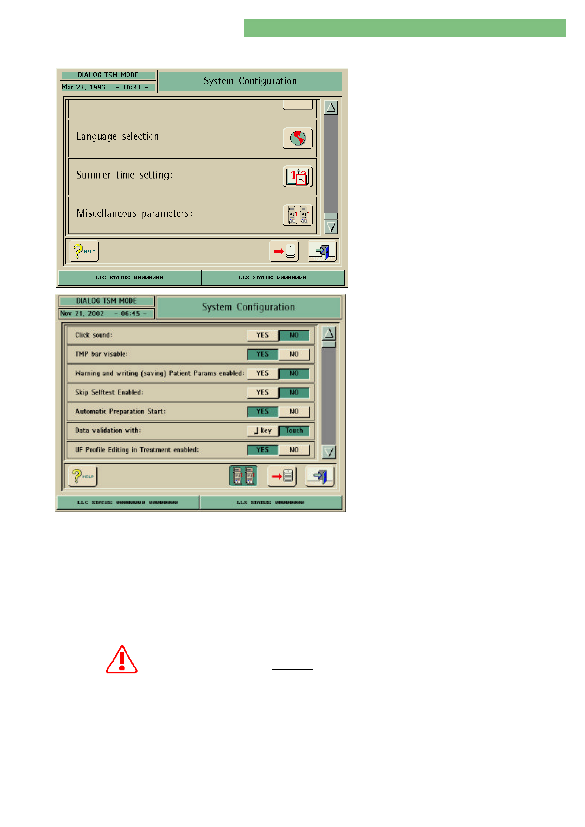
4. TSM Service Program 6/2004 4 49
Dialog/Dialog Advanced
4.9.1.17 Miscellaneous Parameters
Further parameters can be set in the Miscellaneous
Parameters menu.
1. Activate the System Configuration menu with
the System Configuration button in menu
Treatment Support. The following menu is
opened and displayed (scroll with scroll bar).
2. Activate the Miscellaneous Parameters menu
with the Miscellaneous Parameters icon. The
following menu is displayed.
Click Sound
TMP Bar Visible
Warning for Patient Data Saving
The following parameters can be set:
• Click Sound
• TMP Bar Visable
• Warning for Patient Data Saving
• Skip Selftests Enabled
• Automatic Preparation Start
• Data Validation with
• UF Profile No. 10 Setting
• Manual Bypass Confirmation Window Enabled
• End of Therapy Sound Duration
• Automatic Reinfusion Start at Entering End of
Treatment
• DCI (Dianet Address/Data Set)
• DBI (Baud Rate/Data Set)
If you acitvate the YES button a click sound is activated if a button or the touch
screen is pressed.
If you click the YES button you can activate a TMP display in the therapy mode.
The TMP display is only visible in therapy.
If you click the YES button you can generate a warning message to save the
patient data in the following cases:
• The patient data was loaded from the floppy disk drive
• The therapy was terminated without saving the patient data
Automatic Preparation Start
UF Profile No. 10 Setting
MT-MD-DE08C M.KAY
DialogAd_sm_Chapter 4-1_6-2004.doc/pdf <120304> ddmmyy
Skip Self tests Enabled It is not permitted to activate the Skip Selftest Enable function!
It is prohibited to run a therapy with a patient if the selftest was not
passed successfully!
Preparation is started after the machine is switched on, if the machine was in
therapy selection mode when switched off.
Data Validation with
Data acknowledgement can either be performed with the touch screen or the
keyboard.
The editing of the UF profiles can be performed in treatment.
B. Braun Medizintechnologie GmbH
Page 50

4. TSM Service Program 6/2004 4 50
Dialog/Dialog Advanced
Manual Bypass Confirmation
End of Therapy Sound Duration
Automatic Reinfusion Start at
Entering End of Treatment
DCI (Dianet Address/Data Set)
DBI (Baud Rate/Data Set)
4.9.1.18 DBI Parameters
Window Enabled
The confirmation window for bypass can be enabled with YES. Thus every bypass
switching must be confirmed manually.
The duration of the sound can be reduced at the end of a therapy.
A window is automatically opened at the end of therapy. This window must be
confirmed at the end of the therapy for the reinfusion of the blood.
For detailed information regarding networking for Dialog machines see the
technical information 4/00 - Dialog Communication Interface DCI!
For detailed information regarding networking for Dialog machines see the
technical information: Nexadia BSL Network and the respective software for
networking!
For detailed information regarding networking for Dialog machines see the
technical information: Nexadia BSL Network and the respective software for
networking!
MT-MD-DE08C M.KAY
DialogAd_sm_Chapter 4-1_6-2004.doc/pdf <120304> ddmmyy
B. Braun Medizintechnologie GmbH
Page 51
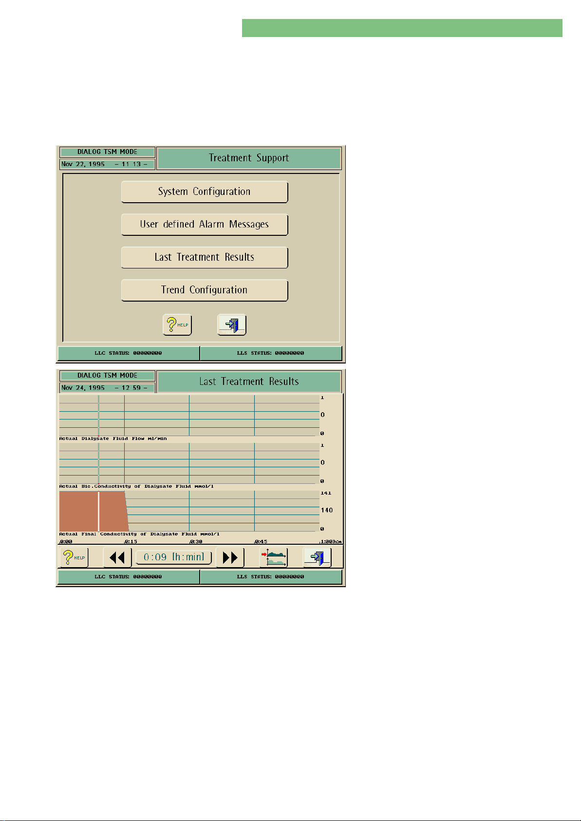
4. TSM Service Program 6/2004 4 51
Dialog/Dialog Advanced
4.9.2 User Defined Alarm Messages
4.9.3 Last Treatment Results
The function User Defined Alarm Messages is not available for software ≤ 6.XX.
The last treatment results can be displayed. The time base can be selected. Five
different graphic blocks can be selected. Three treatment parameters for every
block can be configured individually.
1. Activate the Treatment Support menu with the
Treatment Support key in the TSM Main Menu.
The following menu is opened.
Cursor (left and right)
Time Display
2. Activate the Last Treatment Results menu with
the Last Treatment Results key in the Treatment
Support menu. The following menu is opened
and displayed.
The following settings can be selected:
• Cursor (left and right)
• Time display
• Selection of trend groups
You can shift the time base in one minute increments with the left or right
cursor. The time is displayed in the Time Display window. A specific time can be
selected in the graphics with the time base. Thus the corresponding events can
be displayed.
You can position the time base on a certain treatment time. The corresponding
events can be displayed.
Selection of Trend Groups
MT-MD-DE08C M.KAY
DialogAd_sm_Chapter 4-1_6-2004.doc/pdf <120304> ddmmyy
You can select the Trend Groups menu. Five trend groups with three treatment
parameters each, can be configured individually.
B. Braun Medizintechnologie GmbH
Page 52
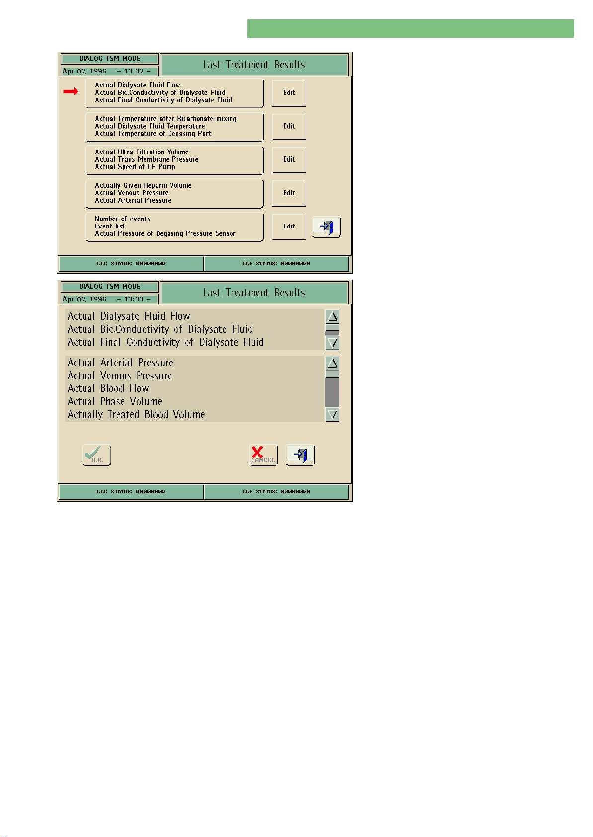
4. TSM Service Program 6/2004 4 52
Dialog/Dialog Advanced
The trend group to be displayed can be selected (red
arrow). You can select three treatment parameters
from a list for one group with the Edit key.
1. Press the Edit key to select treatment
parameters.
2. Select the parameter from the top field (if
necessary use scroll bar) that you would like to
exchange.
3. Select the new parameter from the bottom field
(if necessary use scroll bar) that you would like
to take over.
4. Press the OK key. The new parameter is taken
over.
MT-MD-DE08C M.KAY
DialogAd_sm_Chapter 4-1_6-2004.doc/pdf <120304> ddmmyy
B. Braun Medizintechnologie GmbH
Page 53
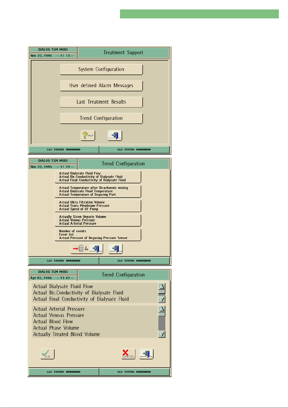
4. TSM Service Program 6/2004 4 53
Dialog/Dialog Advanced
4.9.4 Trend Configuration
You can select five different trend groups for the treatment mode. Three
treatment parameters can be configured individually for every group.
1. Activate the Treatment Support menu with the
Treatment Support key in the TSM Main Menu.
The following menu is opened.
2. Activate the Last Trend Configuration menu with
the Trend Configuration key in the Treatment
Support menu. The following menu is opened
and displayed.
MT-MD-DE08C M.KAY
DialogAd_sm_Chapter 4-1_6-2004.doc/pdf <120304> ddmmyy
3. Select a trend group. The following menu is
opened and displayed.
4. Select the parameter (if necessary use scroll bar)
that you would like to exchange.
5. Select the new parameter (if necessary use scroll
bar) that you would like to take over.
6. Press the OK key. The new parameter is taken
over.
B. Braun Medizintechnologie GmbH
Page 54
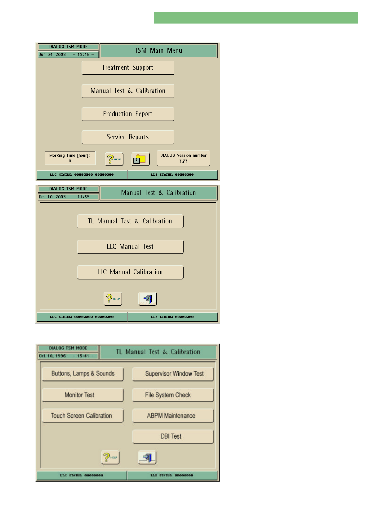
4. TSM Service Program 6/2004 4 54
Dialog/Dialog Advanced
4.10 Manual Test and Calibration
The menu contains test and calibration functions.
The user can test all basic operations and calibrate
components (e.g. sensors and pumps).
The TSM Main Menu appears after the machine is
switched on.
1. Activate the Manual Test and Calibration menu
with the Manual Test and Calibration key in the
TSM Main Menu. The following menu is opened.
4.10.1 TL Manual Test and Calibration
MT-MD-DE08C M.KAY
DialogAd_sm_Chapter 4-2_6-2004.doc/pdf <120304> ddmmyy
In the TL Manual Test and Calibration menu you can
perform the functional tests and a touch screen
calibration method for the top level system and
options also connected to top level system.
1. Activate the TL Manual Test and Calibration
menu with the TL Manual Test and Calibration
key.
B. Braun Medizintechnologie GmbH
Page 55
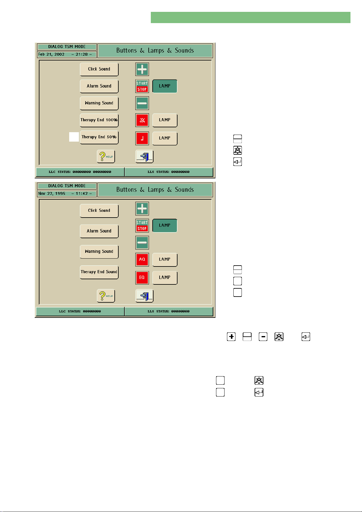
4. TSM Service Program 6/2004 4 55
Dialog/Dialog Advanced
4.10.1.1 Buttons, Lamps and Sounds
(*)
Software Software ≥≥ 3.46 3.46 / (*) ≥ 5.XX
1. Activate the Buttons, Lamps and Sounds menu
with the Buttons, Lamps and Sounds key in the
TL Manual Test and Calibration menu. The
following menu is displayed.
The following parameters can be checked:
• Click Sound
• Alarm Sound
• Warning Sound
• Therapy End 100%
• Therapy End 50% (* SW ≥ 5.XX)
START
STOP
•
LED
• LED
• LED
Software < 3.46Software < 3.46
1. Activate the Buttons, Lamps and Sound menu
with the Buttons, Lamps and Sound key in the
TL Manual Test and Calibration menu. The
following menu is displayed.
The following parameters can be checked:
• Click Sound
• Alarm Sound
• Warning Sound
• Therapy End Sound
START
STOP
•
•
•
AQ
EQ
LED
LED
LED
You can test the keys and lamps of the menbrane keyboard and the sounds. You
START
can test the function of the -,
STOP
-, -, -, and keys and the
respective LEDs. You can also test the different sounds: click sound, alarm and
warning sounds.
Inscription on Keys SW < 3.46 SW ≥ 3.46
Acknowledge alarms:
Acknowledge entries:
AQ
EQ
MT-MD-DE08C M.KAY
DialogAd_sm_Chapter 4-2_6-2004.doc/pdf <120304> ddmmyy
B. Braun Medizintechnologie GmbH
Page 56
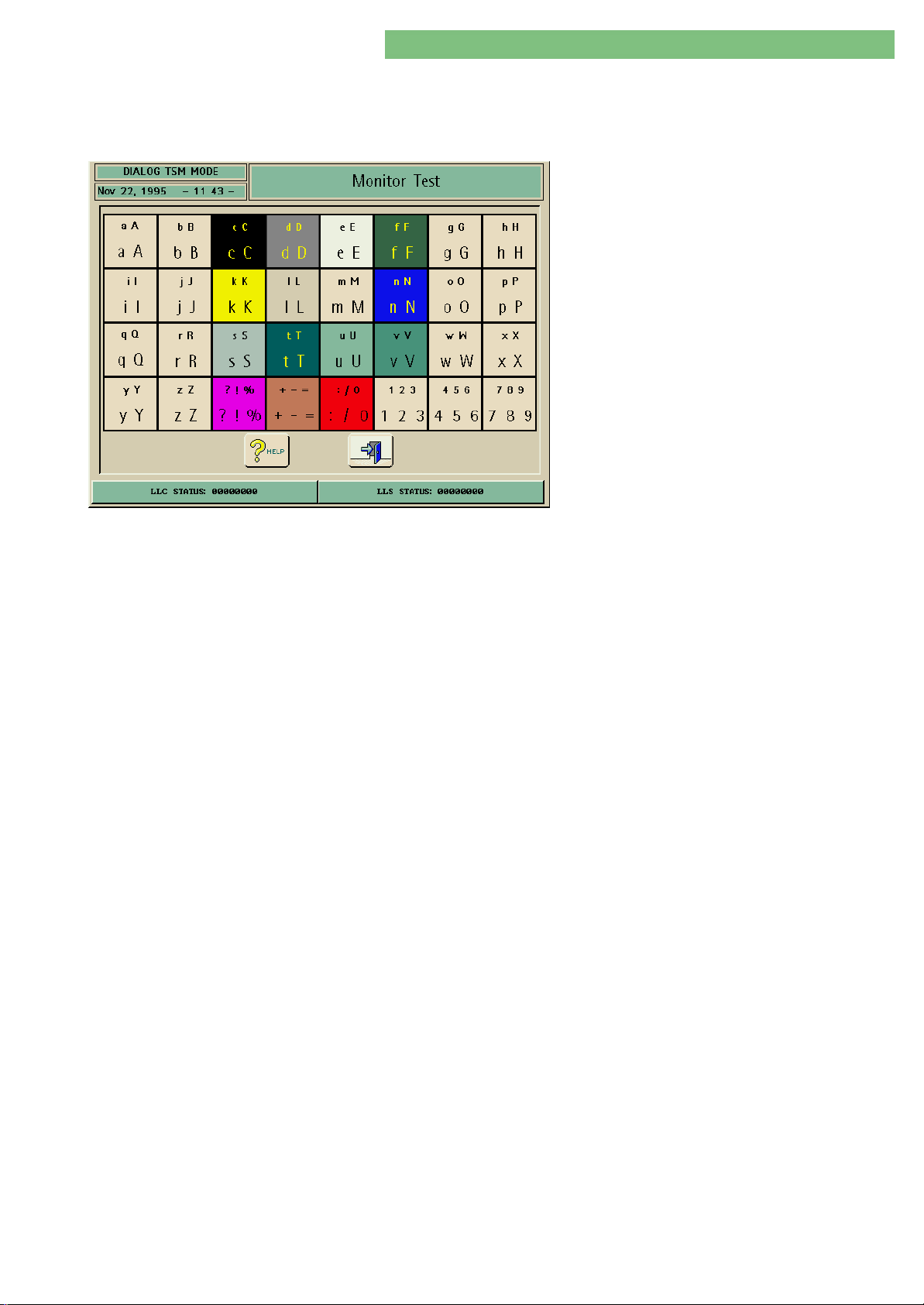
4. TSM Service Program 6/2004 4 56
Dialog/Dialog Advanced
4.10.1.2 Monitor Test
A table appears with all colours. Every square contains an alphanumerical
character with different character fonts. The brightness and the contrast of the
monitor can be checked with this test image.
1. Activate the Monitor Test menu with the
Monitor Test key in the TL Manual Test and
Calibration menu. The following menu is
displayed.
MT-MD-DE08C M.KAY
DialogAd_sm_Chapter 4-2_6-2004.doc/pdf <120304> ddmmyy
B. Braun Medizintechnologie GmbH
Page 57
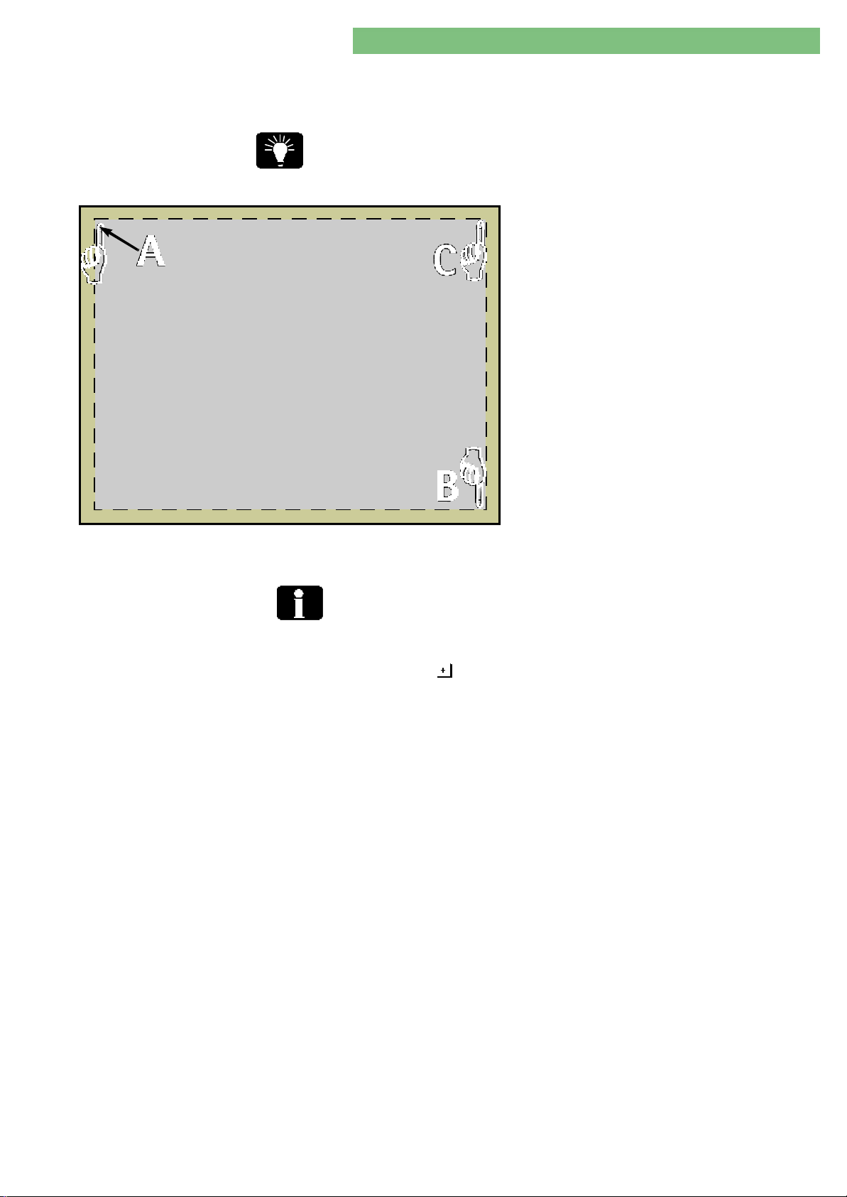
4. TSM Service Program 6/2004 4 57
Dialog/Dialog Advanced
4.10.1.3 Touch Screen Calibration
Touch Screen Calibration
Please touch this point!
The touch screen can be calibrated.
The active part of the touch screen is displayed in the figure. Three corner points
are used (AA, BB and CC) for the calibration. The touch area is defined by the
calibration. To ensure an accurate calibration tip on the finger tip of the symbol
during calibration.
1. Activate the Touch Screen Calibration menu
with the Touch Screen Calibration key in the TL
Manual Test and Calibration menu. The
following menu is displayed.
2. Tip the finger symbol AA in the upper left corner.
The first calibration point is defined.
3. Tip the finger symbol BB in the lower right
corner. The second calibration point is defined.
4. Tip the finger symbol CC in the upper right
corner. The third calibration point is defined. The
calibration data is stored. The intial menu is
automatically displayed again.
5. Switch the Dialog off and on again. The new
calibration data are loaded for the touch screen.
Reset Default Values
6. Check the touch screen.
If the touch screen is out of function (e.g. after a faulty calibration) the default
values for the touch screen can be downloaded.
Take the following steps to reset the default values for the touch screen:
1. Press the key of the blood pump keyboard three times in the TSM Main
Menu.
2. Switch machine off and on again. The old default data is restored.
MT-MD-DE08C M.KAY
DialogAd_sm_Chapter 4-2_6-2004.doc/pdf <120304> ddmmyy
B. Braun Medizintechnologie GmbH
Page 58
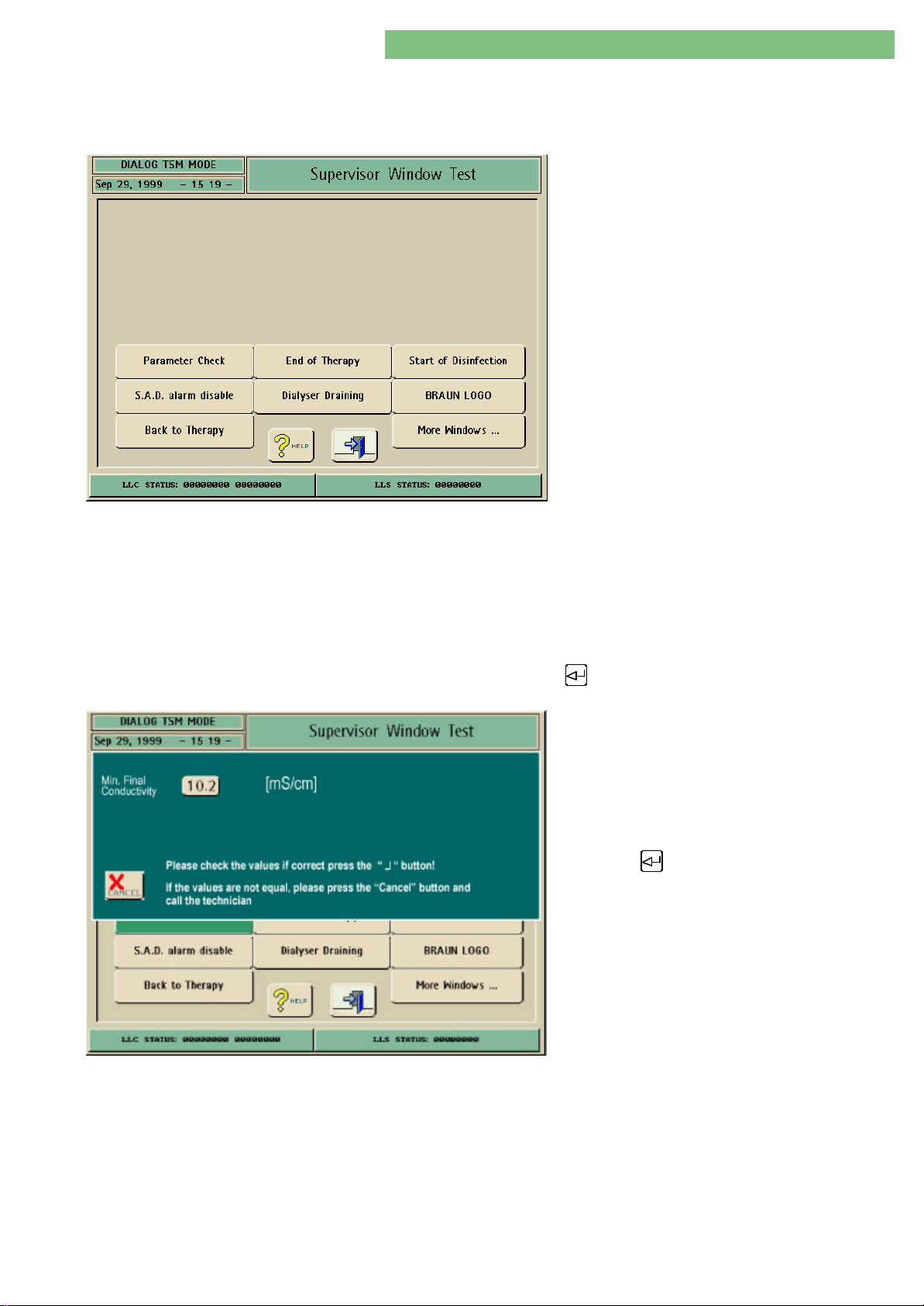
4. TSM Service Program 6/2004 4 58
Dialog/Dialog Advanced
4.7.1.4 Supervisor Window Test
The position and data of the selected supervisor window is displayed. You can
close the window with the Cancel key.
1. Activate the Supervisor Window Test menu with
the Supervisor Window Test key in the TL
Manual Test and Calibration menu. The
following menu is displayed.
The following supervisor windows can be checked:
• Parameter Check
• SAD Alarm Disable
• Back to Therapy
• End of Therapy
• Dialyser Draining
• Start of Disinfection
• Braun Logo
More Windows ...:
• Multi Window
• UF Time and Max. UF Rate
• Connecting Patient
• MW with Substitution Volume
• Min. and Max. Final Conductivity
• UF Volume and Max. UF Rate
• Skip Selftests
• Reinfusion
The parameter check is displayed as an example
The position of the supervisor window and the data of the Minimal Final
Conductivity is displayed. You can either close the supervisor window with the
Cancel key or select and acknowledge the single parameters and close the
supervisor window with the key.
2. Activate the Parameter Check window with the
Parameter Check key. The following menu is
displayed.
3. Press the Cancel key to close the supervisor
window.
or
Press the key to select and acknowledge the
single parameters and close the supervisor
window.
MT-MD-DE08C M.KAY
DialogAd_sm_Chapter 4-2_6-2004.doc/pdf <120304> ddmmyy
B. Braun Medizintechnologie GmbH
Page 59
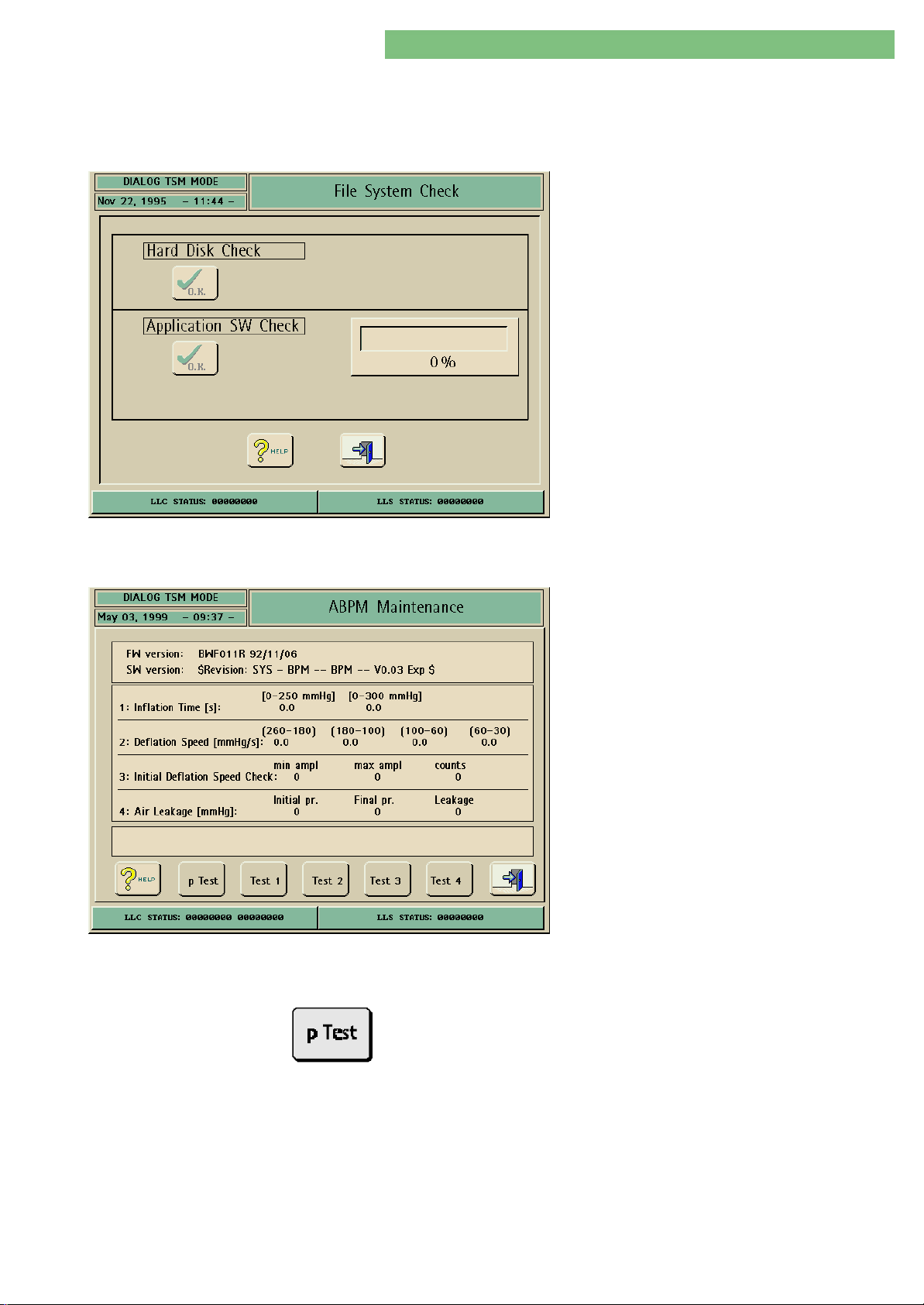
4. TSM Service Program 6/2004 4 59
Dialog/Dialog Advanced
4.7.1.5 File System Check
Press the OK key to start the check of the Dialog file system. This function reads
all executable files and creates a check value. If it does not equal with the
original check value a warning message is displayed.
1. Activate the Test System Check menu with the
Test System Check key in the TL Manual Test
and Calibration menu. The following menu is
displayed.
2. Press the OK key of the Hard Disk Check to test
the hard disk drive.
or
Press the OK key of the Application SW Check to
test the application software.
4.10.1.6 ABPM Maintenance
Pressure Comparison Test
1. Activate the ABPM Maintenance menu with the
ABPM Maintenance key in the TL Manual Test
and Calibration menu. The following menu is
displayed.
The ABPM Maintenance menu is used for the
function test of the Dialog automatic blood pressure
measurement ABPM option. The cuff is replaced by
a 500 ml measurement chamber.
The following functions can be tested:
• P Test (Pressure Comparison Test)
• Test 1 (Inflation Time)
• Test 2 (Deflation Speed)
• Test 3 (Initial Deflation Speed Check)
• Test 4 (Air Leakage)
See chapter 5 technical safety inspection and
preventive maintenance: inspection protocol for the
automatic blood pressure measurement ABPM and
the execution procedure for the measurement
inspection.
The P Test key activates and deactivates the pressure comparison test of the
ABPM. The P Test is used to compare the pressure value of the pressure sensor
with a reference instrument.
A reference instrument (accuracy ≤ ± 0.5 mmHg) is required for the comparison
test of the pressure sensor.
MT-MD-DE08C M.KAY
DialogAd_sm_Chapter 4-2_6-2004.doc/pdf <120304> ddmmyy
B. Braun Medizintechnologie GmbH
Page 60
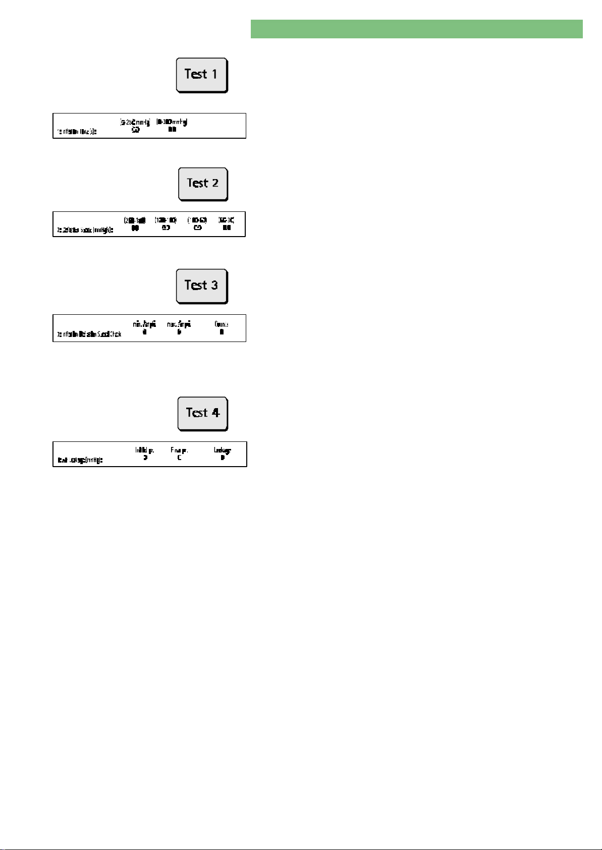
4. TSM Service Program 6/2004 4 60
Dialog/Dialog Advanced
Inflation Time [s]
Deflation Speed [mmHg/s]
Initial Deflation Speed Check
The Test 1 key activates and deactivates the inflation time. Thus the inflation
time of the pump is tested up to 300 mmHg, i.e.:
• 0 - 250 mmHg
• 0 - 300 mmHg
The measurement chamber is connected to the ABPM system via the pressure
tubing. A pressure is built up to 300 mmHg.
The Test 2 key activates and deactivates the deflation speed. Thus the deflation
speed of the deflation valve is tested. The deflation starts at 300 mmHg.
The measurement chamber is connected to the ABPM system via the pressure
tubing. A pressure is built up to 300 mmHg. The deflation speed is devided in 4
steps: : 260 - 180 mmHg, 180- 100 mmHg, 100 - 60 mmHg and 60 - 30 mmHg.
The Test 3 key activates and deactivates the initial deflation speed check. Thus
the initial deflation speed of the ABPM is tested.
The measurement chamber is connected to the ABPM system via the pressure
tubing. A pressure is built up to 300 mmHg. The initial deflation speed is checked:
• Min. amplitude
• Max. amplitude
• Counts
Air Leakage [mmHg]
4.10.1.7 DBI Test
The Test 4 key activates and deactivates the air leakage test (3 minutes). Thus
the pneumatic integrity of the ABPM system is tested.
The measurement chamber is connected to the ABPM system via the pressure
tubing. A pressure is built up to 300 mmHg and is held for 3 minutes.
For detailed information regarding networking for Dialog machines see the
technical information: Nexadia BSL Network and software for networking!
MT-MD-DE08C M.KAY
DialogAd_sm_Chapter 4-2_6-2004.doc/pdf <120304> ddmmyy
B. Braun Medizintechnologie GmbH
Page 61
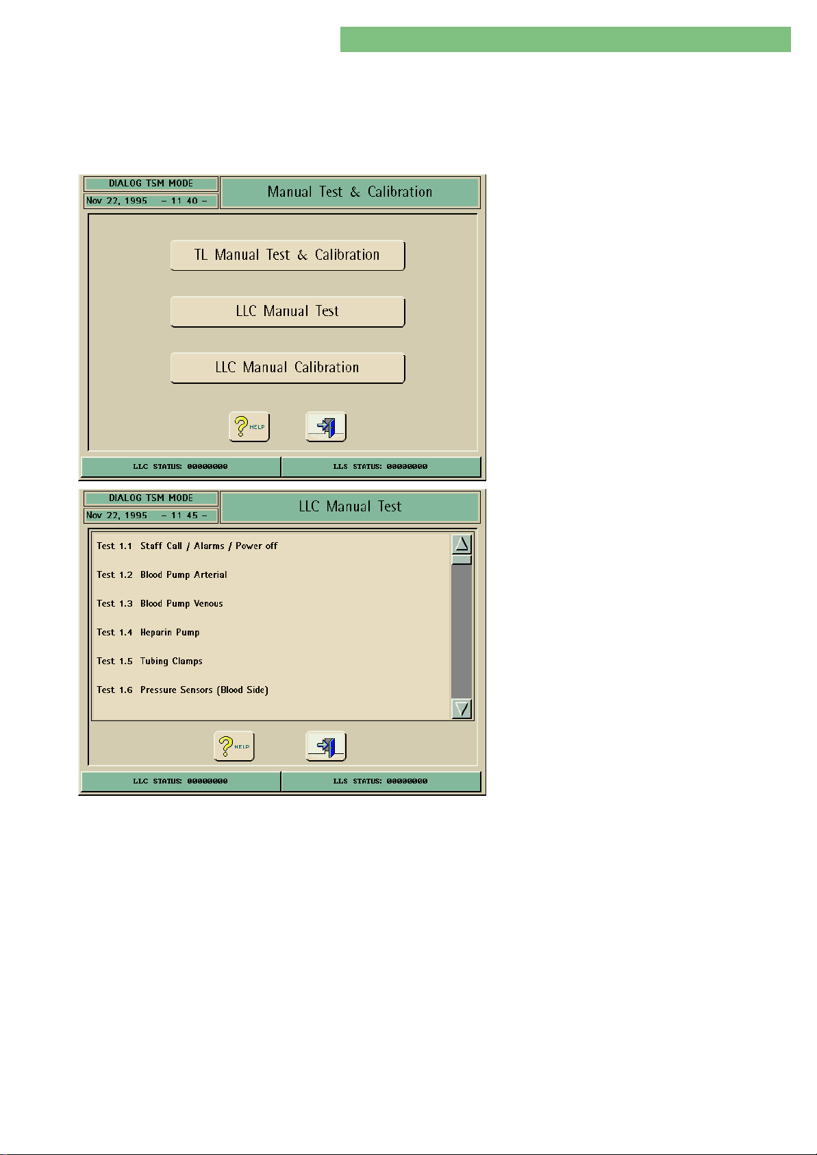
4. TSM Service Program 6/2004 4 61
Dialog/Dialog Advanced
4.10.2 LLC Manual Test
You can test the function of the low level controller LLC sensors, pumps and
valves. You can select a test menu and check a single (or where applicable
combined) sensor, pump and valve. The components are displayed in graphics
(position and corresponding value is displayed). Additionally you can directly skip
to the Low Level Calibration menu with a Calibration key.
1. Activate the Manual Test and Calibration menu
with the Manual Test and Calibration key in the
TSM Main Menu. The following menu is
displayed.
2. Activate the LLC Manual Test menu with the LLC
Manual Test key in the Manual Test and
Calibration menu. The following menu is
displayed (if necessary use scroll bar).
The following tests can be selected:
• 1.1 Staff Call, Alarms, Power off
• 1.2 Blood Pump Arterial
• 1.3 Blood Pump Venous, Substitution Pump
• 1.4 Heparin Pump
• 1.5 Tubing Clamps
• 1.6 Pressure Sensors (Blood Side)
• 1.7 Air Sensor, Red Sensor
• 1.8 Coupling Detectors
• 1.9 Water Intake, Upline Tank and Flow Pump
FPE
• 1.10 Degassing and Heating
• 1.11 Dialysis Temperature
• 1.12 Concentrate Pumps and Conductivity
• 1.13 Balance Chamber Valves
• 1.14 Bypass and Disinfection Valves
• 1.15 Flow Pump FPA, Balance Chamber and Air
Separator
• 1.16 Pressure Water Part
• 1.17 UF Pump
• 1.18 Blood Leak
• 1.19 Leak Test
• 1.20 Water Part (Overview)
• 1.21 Emptying
• 1.22 HDF
• 1.23 BIC Cartridge Valve and Coupling Detectors
• 1.24 HDF Online
• 1.25 HDF Online Valves and Coupling Detectors
• 1.26 Option Rechargeable Battery
• 1.27 DFS Pressure Test of Therapy
MT-MD-DE08C M.KAY
DialogAd_sm_Chapter 4-2_6-2004.doc/pdf <120304> ddmmyy
B. Braun Medizintechnologie GmbH
Page 62
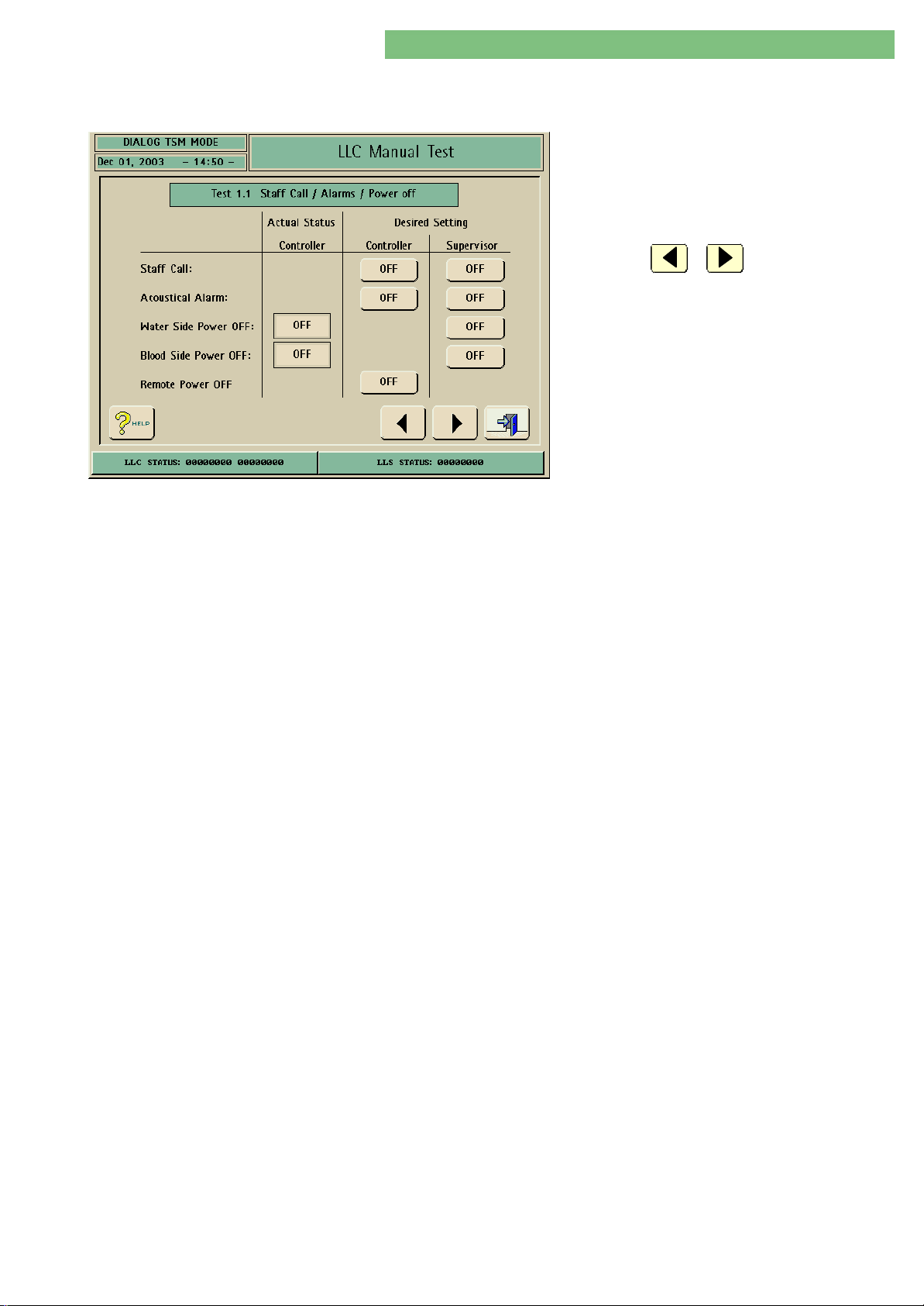
4. TSM Service Program 6/2004 4 62
Dialog/Dialog Advanced
4.10.2.1 Test 1.1 Staff Call,
Alarms, Power Off
Staff Call/
Acoustical Alarm
1. Activate the Staff Call/Alarms/Power Off menu
with the Staff Call/Alarms/Power Off key in the
LLC Manual Test menu. The following menu is
displayed.
2. Check the functions with the appropriate keys.
3. Press the or key to skip to the last
or to the next test point.
The staff call can be activated with the PRUF/PRUF-S signal and the acoustical
alarm can be switched separately with the ACAL/ACAL-S signal by the controller
and supervisor.
Water Side Power OFF
Blood Side Power OFF
Remote Power OFF
The low level supervisor can test the power off for the 24 V supply voltage with
the D24OFF-S signal for the dialysate side power off. The feedback to the
controller (ON/OFF) shows whether the voltage was switched.
The low level supervisor can test the power off for the 24 V supply voltage with
the B24OFF-S signal for the blood side power off. The feedback to the controller
(ON/OFF) shows whether the voltage was switched.
The REMOTE signal for the remote power off can be activated by the controller.
The machine is switched off by the internal real time clock RTC. The machine is
switched on again after the shortest time period (approx. 64 s) has expired. The
machine can be switched on immediately, if the machine is switched off and on
again.
MT-MD-DE08C M.KAY
DialogAd_sm_Chapter 4-2_6-2004.doc/pdf <120304> ddmmyy
B. Braun Medizintechnologie GmbH
Page 63
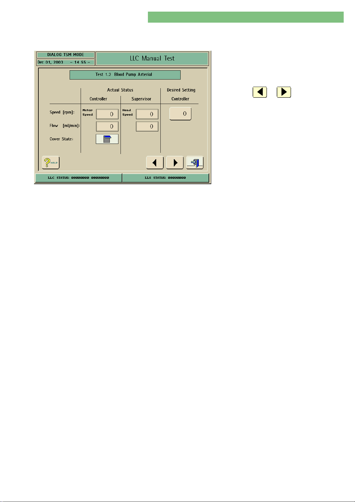
4. TSM Service Program 6/2004 4 63
Dialog/Dialog Advanced
4.10.2.2 Test 1.2 Blood Pump
Arterial
Speed
1. Activate the Blood Pump Arterial menu with the
Blood Pump Arterial key in the LLC Manual Test
menu. The following menu is displayed.
2. Check the functions with the appropriate keys.
3. Press the or key to skip to the
previous or to the next test point.
You can select the speed of the arterial blood pump BPABPA. The controller displays
the motor speed. The supervisor displays the head speed. The speed is kept stable
via a hardware controller but it is not controlled to the desired set-point, i.e. the
actual value does not have to correspond with the desired set-point value. The
low level controller detects the motor speed via Hall sensors. These are integrated
in the motor.
Flow
Cover State
The supervisor detects the speed via a slot disk (with light barrier) assembled on
the pump head axle. The conversion factor for the gear of the pump has a ratio of
1:46.65 between both actual values.
The controller displays the calculated flow rate.
If the pump cover is opened the blood pump BPABPA is stopped. The low level
controller detects and displays the opened pump cover.
MT-MD-DE08C M.KAY
DialogAd_sm_Chapter 4-2_6-2004.doc/pdf <120304> ddmmyy
B. Braun Medizintechnologie GmbH
Page 64
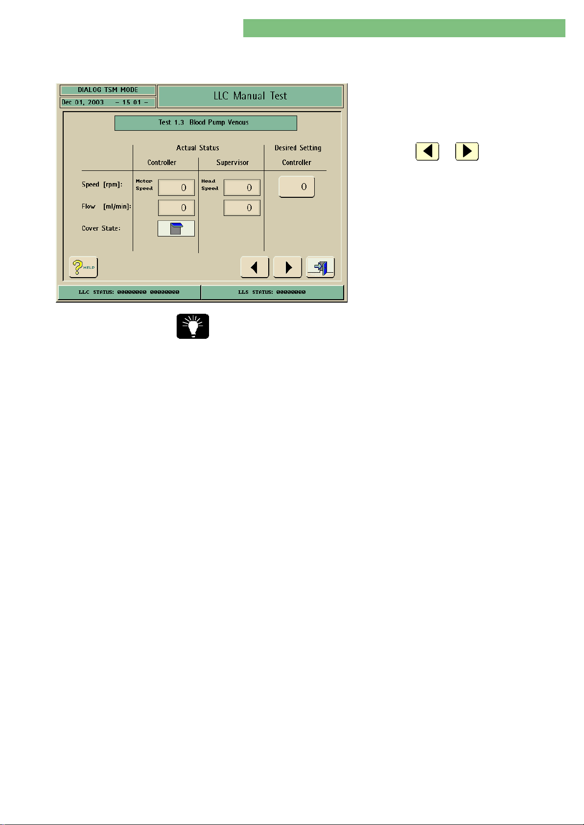
4. TSM Service Program 6/2004 4 64
Dialog/Dialog Advanced
4.10.2.3 Test 1.3 Blood Pump Venous,
Substitution Pump
1. Activate the Blood Pump Venous menu with the
Blood Pump Venous key in the LLC Manual Test
menu. The following menu is displayed.
2. Check the functions with the appropriate keys.
3. Press the or key to skip to the
previous or to the next test point.
The BPVBPV pump has an own tubing factor for in substitution mode (2.13 Flow of
BPA and BPV/Substitution Pump menu). The flow for the BPVBPV substitution is
displayed with this factor.
Speed
Cover State
You can select the speed of the venous blood pump BPVBPV /substitution pump. The
controller displays the motor speed. The supervisor displays the head speed. The
speed is kept stable via a hardware controller but it is not controlled to the desired
set-point, i.e. the actual value does not have to correspond with the desired setpoint value. The low level controller detects the motor speed via Hall sensors.
These are integrated in the motor. The low level supervisor detects the speed via a
slot disk (with light barrier) assembled on the pump head axle. The conversion
factor for the gear of the pump has a ratio of 1:46.65 between both actual
values.
If the pump cover is opened the blood pump BPVBPV /substitution pump is stopped.
The low level controller detects and displays the opened pump cover.
MT-MD-DE08C M.KAY
DialogAd_sm_Chapter 4-2_6-2004.doc/pdf <120304> ddmmyy
B. Braun Medizintechnologie GmbH
Page 65
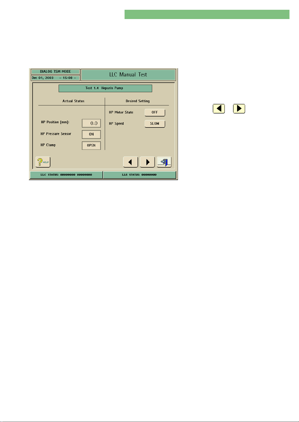
4. TSM Service Program 6/2004 4 65
Dialog/Dialog Advanced
4.10.2.4 Test 1.4 Heparin Pump
Heparin Pump Compact
The heparin pump type is selected in LLC Manual Calibration, Calibration 2.2
Heparin Pump, Heparin Pump Type, Heparin Pump Type Selection :
• Heparin Pump Comfort
• Heparin Pump Compact
1. Activate the Heparin Pump menu with the
Heparin Pump key in the LLC Manual Test
menu. The following menu is displayed for the
heparin pump Compact.
2. Check the functions with the appropriate keys.
3. Press the or key to skip to the
previous or to the next test point.
HP Position [mm]
HP Syringe Sensor
Lock Sensor
HP Motor State
HP Speed
The forward feed distance is displayed in mm (only if the syringe is inserted and
locked). The counter is reset if the lock sensor is opened. The distance is detected
from the signal of the light barrier on the motor axle.
The sensor for the sensor plate of the syringe detects an inserted syringe.
Sensor to open the clasp nut.
(The clasp nut is assembled on the drive spindle and limits the max. pressure load
of the heparin pump).
Activates/switches off the heparin pump.
Selection between slow and fast forward feed.
MT-MD-DE08C M.KAY
DialogAd_sm_Chapter 4-2_6-2004.doc/pdf <120304> ddmmyy
B. Braun Medizintechnologie GmbH
Page 66
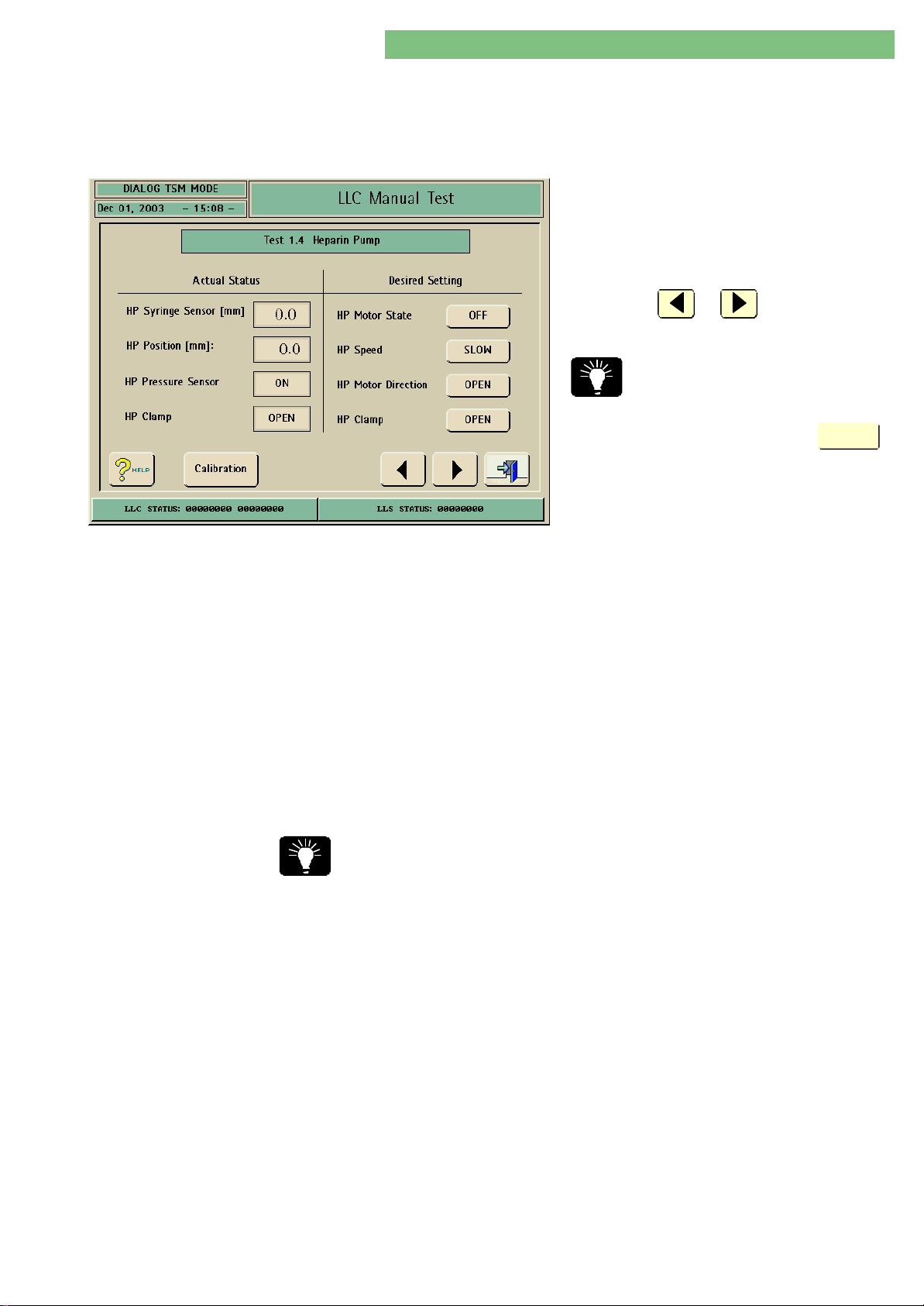
4. TSM Service Program 6/2004 4 66
Dialog/Dialog Advanced
Heparin Pump Comfort
The heparin pump type is selected in LLC Manual Calibration, Calibration 2.2
Heparin Pump, Heparin Pump Type, Heparin Pump Type Selection :
• Heparin Pump Comfort
• Heparin Pump Compact
1. Activate the Heparin Pump menu with the
Heparin Pump key in the LLC Manual Test
menu. The following menu is displayed for the
heparin pump Comfort.
2. Check the functions with the appropriate keys.
3. Press the or key to skip to the
previous or to the next test point.
You can skip directly to the calibration of the
heparin pump Comfortby pressing the
key.
Calibration
HP Syringe Sensor
HP Position
HP Pressure Sensor
HP Clamp
HP Motor State
HP Speed
HP Motor Direction
Heparin Pump Position
Open and Closed
The syringe diameter is displayed in mm with the HPSP signal. If there is no
syringe in the heparin pump a value < 13 mm must be detected.
If the syringe holder is completely opened a value > 39 mm must be detected.
Thereby the software can recognize an opened syring holder.
The HPKOLB signal detects if the drive push button is driven against a syringe
plunger.
The clamps for the syringe are open/closed with the HPKRALLOZU signal. The
clamp position must be recognized with the HPKRALLO signal.
The motor current is switched by the HPON signal for the stepper motor drive.
You can switch to two different speeds to check the basic drive functions of the
heparin pump.
The motor direction is switched by the HPMORI signal for the stepper motor drive.
If necessary switch the Dialog off and on again to repeat the test for the heparin
pump. The HP Speed must be set to SLOW prior to a new setting.
1. Switch the HP Motor Direction key to OPEN and the HP Speed to FAST. Switch
HP Motor Sate key to ON.
Wait until the OPEN position is reached.
Switch the HP Speed to SLOW.
The HP Position [mm] must display 0 mm.
MT-MD-DE08C M.KAY
DialogAd_sm_Chapter 4-2_6-2004.doc/pdf <120304> ddmmyy
2. Open and close the HP Clamp with the OPEN/CLOSED key and check the
Actual Status of the HP Pressure Sensor ON/OFF and HP Clamp OPEN/CLOSED.
Manually press the pressure push button on the heparin pump and check the
Actual Status of the HP Pressure Sensor ON/OFF.
B. Braun Medizintechnologie GmbH
Page 67

4. TSM Service Program 6/2004 4 67
Dialog/Dialog Advanced
3. Switch the HP Motor Direction key to CLOSED and the HP Speed to FAST.
Open and close the HP Clamp 3 times during the opening procedure and
check the Actual Status values.
Wait until the closed position is reached.
Switch the HP Speed to SLOW.
The HP Position [mm] must display 120 mm ± 3 mm.
4. Switch the HP Motor Direction key to OPEN and the HP Speed to FAST.
Open and close the HP Clamp 3 times during the opening procedure and
check the Actual Status values.
Wait until the OPEN position is reached.
Switch the HP Speed to SLOW.
The HP Position [mm] must display 0 mm (+ 1 mm).
Check Inserted Syringe 5. Insert a syringe. Switch the HP Motor Direction key to CLOSED and the HP
Speed to FAST.
Check the HP Pressure Sensor (ON/OFF) when the syringe was recognized.
Check the inserted syringe. The syringe must have a range ≤ 1 ml in the
CLOSED position.
MT-MD-DE08C M.KAY
DialogAd_sm_Chapter 4-2_6-2004.doc/pdf <120304> ddmmyy
B. Braun Medizintechnologie GmbH
Page 68
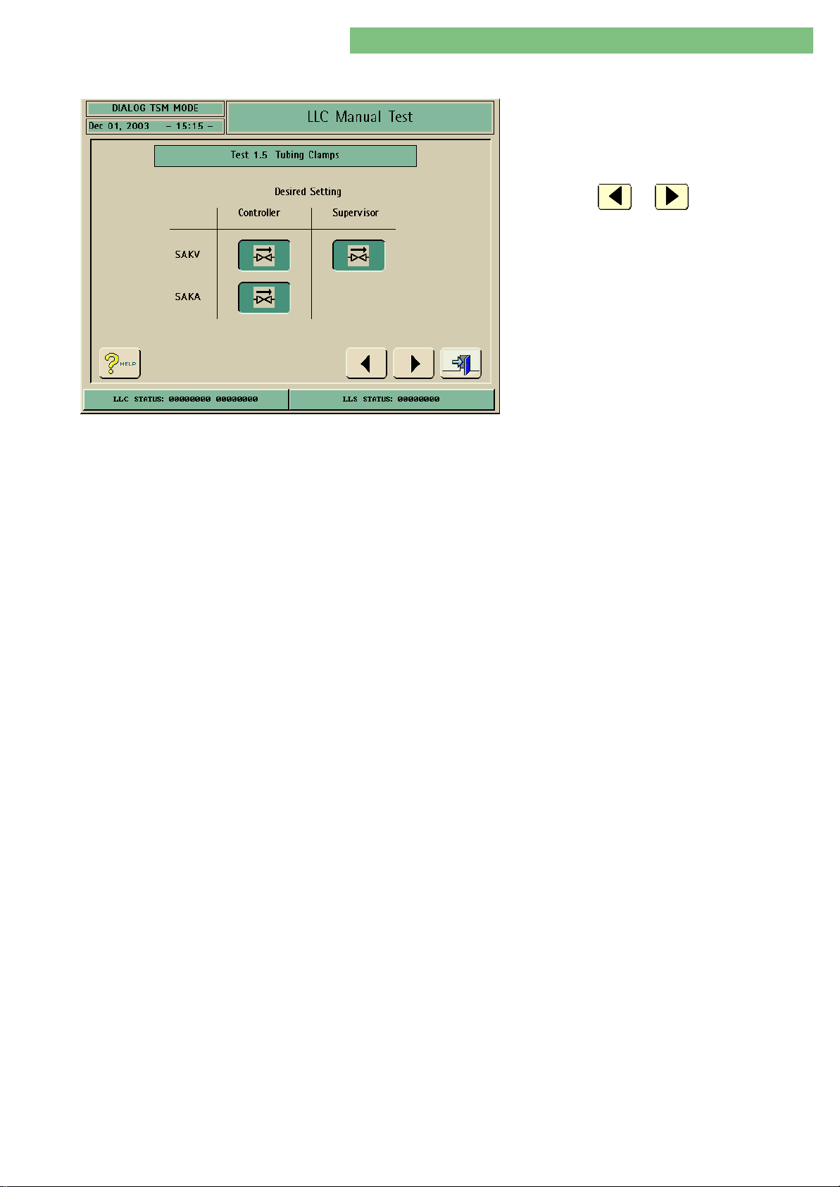
4. TSM Service Program 6/2004 4 68
Dialog/Dialog Advanced
4.10.2.5 Test 1.5 Tubing Clamps
Tubing Clamps
1. Activate the Tubing Clamps menu with the
Tubing Clamps key in the LLC Manual Test
menu. The following menu is displayed.
2. Check the functions with the appropriate keys.
3. Press the or key to skip to the
previous or to the next test point.
The venous tubing clamp SAKVSAKV and arterial tubing clamp SAKASAKA can be closed
and opened. Thereby the switch function and leakage test (pressure - clamp gap,
time) can be tested. The closed clamp gap is set to 1.4 mm + 0.1 mm.
MT-MD-DE08C M.KAY
DialogAd_sm_Chapter 4-2_6-2004.doc/pdf <120304> ddmmyy
B. Braun Medizintechnologie GmbH
Page 69
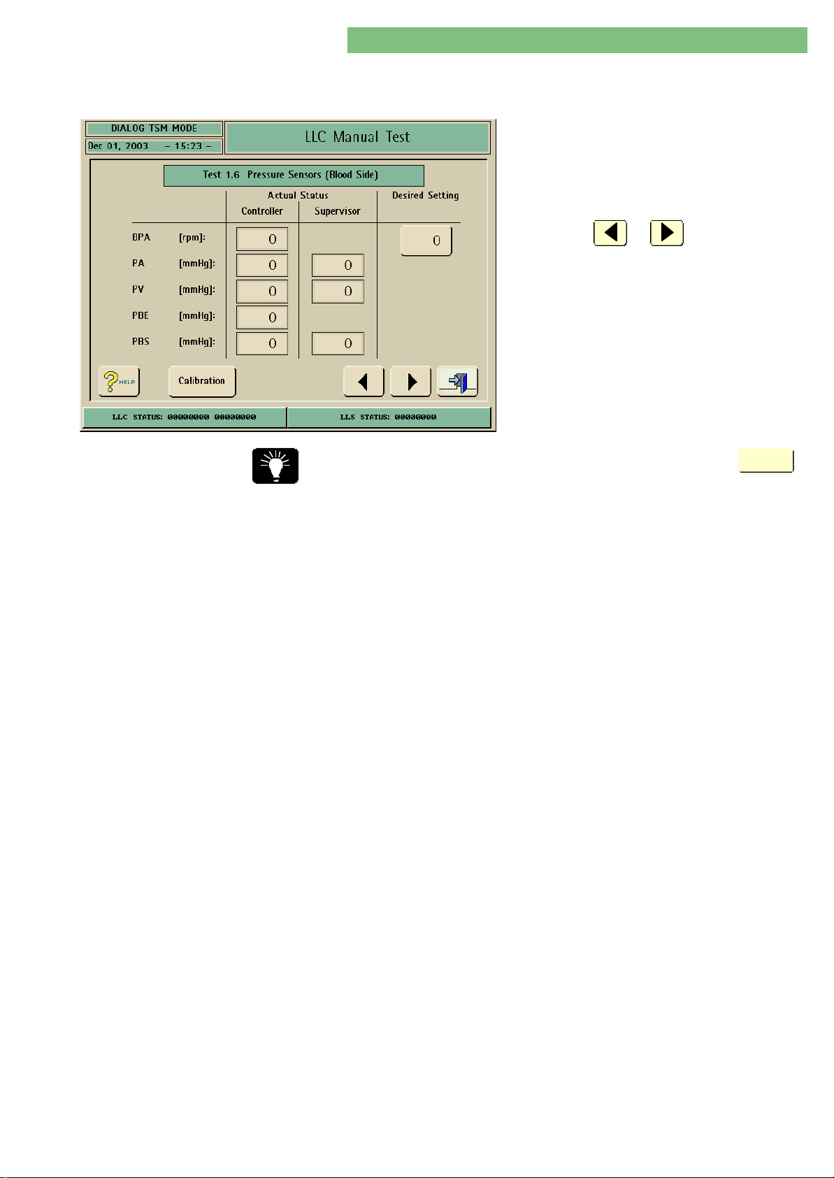
4. TSM Service Program 6/2004 4 69
Dialog/Dialog Advanced
4.10.2.6 Test 1.6 Pressure Sensors
(Blood Side)
1. Activate the Pressure Sensors (Blood Side) menu
with the Pressure Sensors (Blood Side) key in
the LLC Manual Test menu. The following menu
is displayed.
2. Check the functions with the appropriate keys.
3. Press the or key to skip to the
previous or to the next test point.
You can skip directly to the calibration of the sensors by pressing the
key.
Calibration
Pressure Sensors
The values of the pressure sensors PAPA, PVPV , PBEPBE and PBSPBS are displayed. The
sensor pressure can be tested with a syringe.
The value for PBSPBS is 0 if PBSPBS was not activated in the 2.1 Pressure Sensors (Blood
Side) menu.
MT-MD-DE08C M.KAY
DialogAd_sm_Chapter 4-2_6-2004.doc/pdf <120304> ddmmyy
B. Braun Medizintechnologie GmbH
Page 70
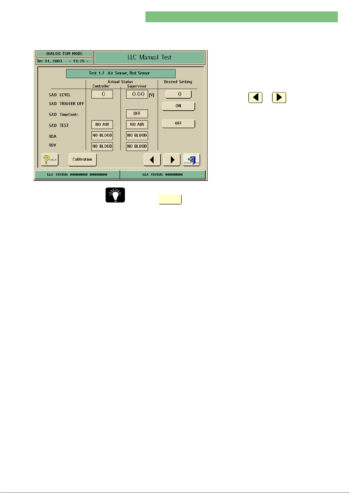
4. TSM Service Program 6/2004 4 70
Dialog/Dialog Advanced
4.10.2.7 Test 1.7 Air Sensor SAD,
Red Sensor
1. Activate the Air Sensor, Red Sensor menu with
the Air Sensor, Red Sensor key in the LLC
Manual Test menu. The following menu is
displayed.
2. Check the functions with the appropriate keys.
3. Press the or key to skip to the
previous or to the next test point.
You can skip directly to the calibration of the safety air detector SADSAD by pressing
Calibration
the
key.
Safety Air Detector Version 1 and 2
SAD with Fixed Alarm Level
(Version 2)
SAD Test
SAD Trigger OFF
SAD Messung
SAD Test
The safety air detector type is selected in LLC Manual Calibration , Calibration 2.9
Safety Air Detector SAD, SAD Type:
• SAD with variable alarm level (version 1)
• SAD with fixed alarm level (version 2)
The calibration of both SADs depends on the SAD types. The calibration level
(example KS = 48) on the SAD is entered for the SAD with a fixed alarm level
(version 2). The alarm level is automatically set to 15 digits (software < 6.21 = 10
digits) after the calibration value is entered. The test level is calculated by adding
5 digits to the calibration level (test level = KS + 5 digits). You can find the
detailed description and procedure for the calibration of the SAD version 2 in the
menu: LLC Manual Calibration , Calibration 2.9 Safety Air Detector SAD.
Activate the internal test of the safety air detector SADSAD with the SAD TEST key
(the switch level is automatically increased), i.e. air must always be detected.
The cyclic measurement of the controller can be checked with the SAD TRIGGER
OFF key.
The cyclic measurement is checked by the controller and must be detected by
the supervisor with the SAD Time Contr.
AIR must be detected if the SAD TEST is activated. The sensitivity can be changed
to check the scwitching point.
AIR
AIR must be detected if a tubing filled with air is inserted.
MT-MD-DE08C M.KAY
DialogAd_sm_Chapter 4-2_6-2004.doc/pdf <120304> ddmmyy
NO AIR
NO AIR must be detected if a tubing filled with fluid is inserted.
B. Braun Medizintechnologie GmbH
Page 71
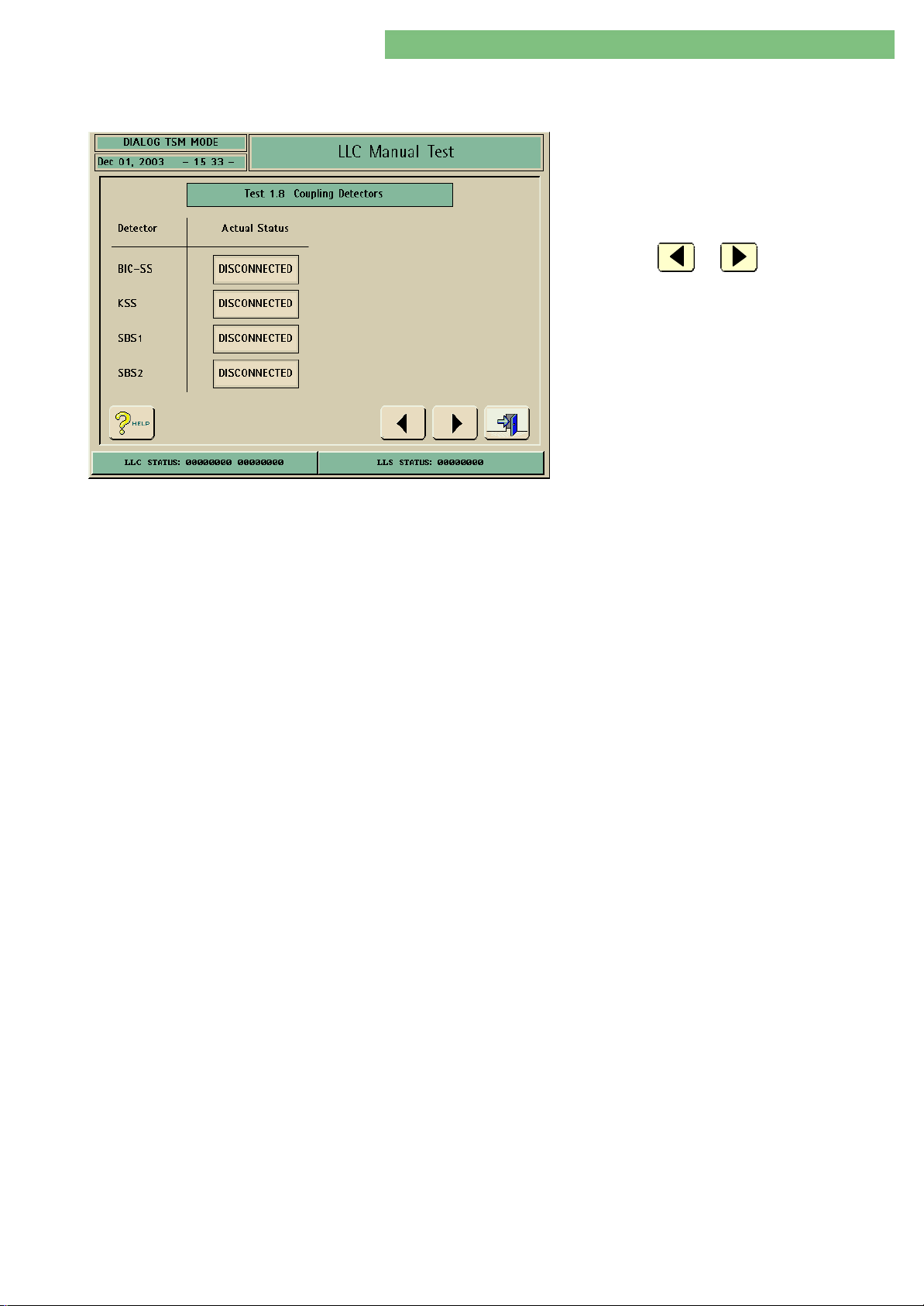
4. TSM Service Program 6/2004 4 71
Dialog/Dialog Advanced
4.10.2.8 Test 1.8 Coupling
Detectors
1. Activate the Coupling Detectors menu with the
Coupling key in the LLC Manual Test menu. The
following menu is displayed.
2. Check the functions of the reed contacts with
the appropriate couplings.
3. Press the or key to skip to the
previous or to the next test point.
You can check the actual status of the reed sensors:
Detectors • BIC SSBIC SS Bicarbonate rinsing connection sensor
• KSSKSS Concentrate rinsing connector sensor
• SBS1/2SBS1/2 Rinsing bridge connector sensor (dialyser couplings)
MT-MD-DE08C M.KAY
DialogAd_sm_Chapter 4-2_6-2004.doc/pdf <120304> ddmmyy
B. Braun Medizintechnologie GmbH
Page 72
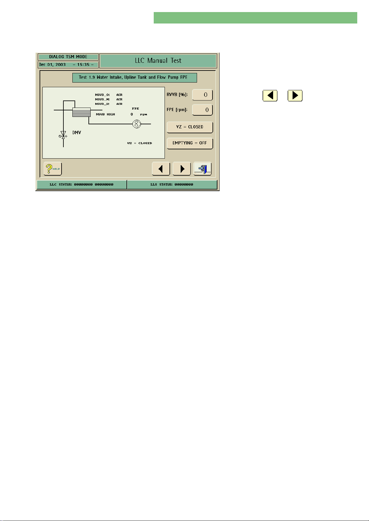
4. TSM Service Program 6/2004 4 72
Dialog/Dialog Advanced
4.10.2.9 Test 1.9 Water Inlet, Upline
Tank and Flow Pump FPE
1. Activate the Water Inlet menu with the Water
Inlet key in the LLC Manual Test menu. The
following menu is displayed.
2. Check the functions with the appropriate keys.
3. Press the or key to skip to the
previous or to the next test point.
You can set the flow of the upline tank control valve RVVBRVVB. RVVBRVVB must
guarantee a flow of ≥ 1200 ml/min at a water inlet pressure of approx. 1.3 bar.
The pressure reducer valve is set to 1.3 bar.
The level of the upline tank VBVB is displayed on the screen by the level sensors
( NSVBNSVB high, medium and low).
If the upline tank is full the valve RVVBRVVB is closed automatically. If the flow pump
FPEFPE is activated FPAFPA is also switched on, to allow an unrestricted flow through
the balance chambers.
The degassing pump PEPE is permanently switched on to allow a circulation in both
compartments of the upline tank.
RVERVE is opened. If the emptying is activated to drain the machine the pumps are
switched on for a short period and RVVBRVVB closed.
All balance chamber valves are opened and the outlet flow pump FPAFPA works in
main flow with the same speed as the inlet flow pump FPEFPE. The degassing pump
EPEP runs and the degassing control valve RVERVE is open.
MT-MD-DE08C M.KAY
DialogAd_sm_Chapter 4-2_6-2004.doc/pdf <120304> ddmmyy
B. Braun Medizintechnologie GmbH
Page 73
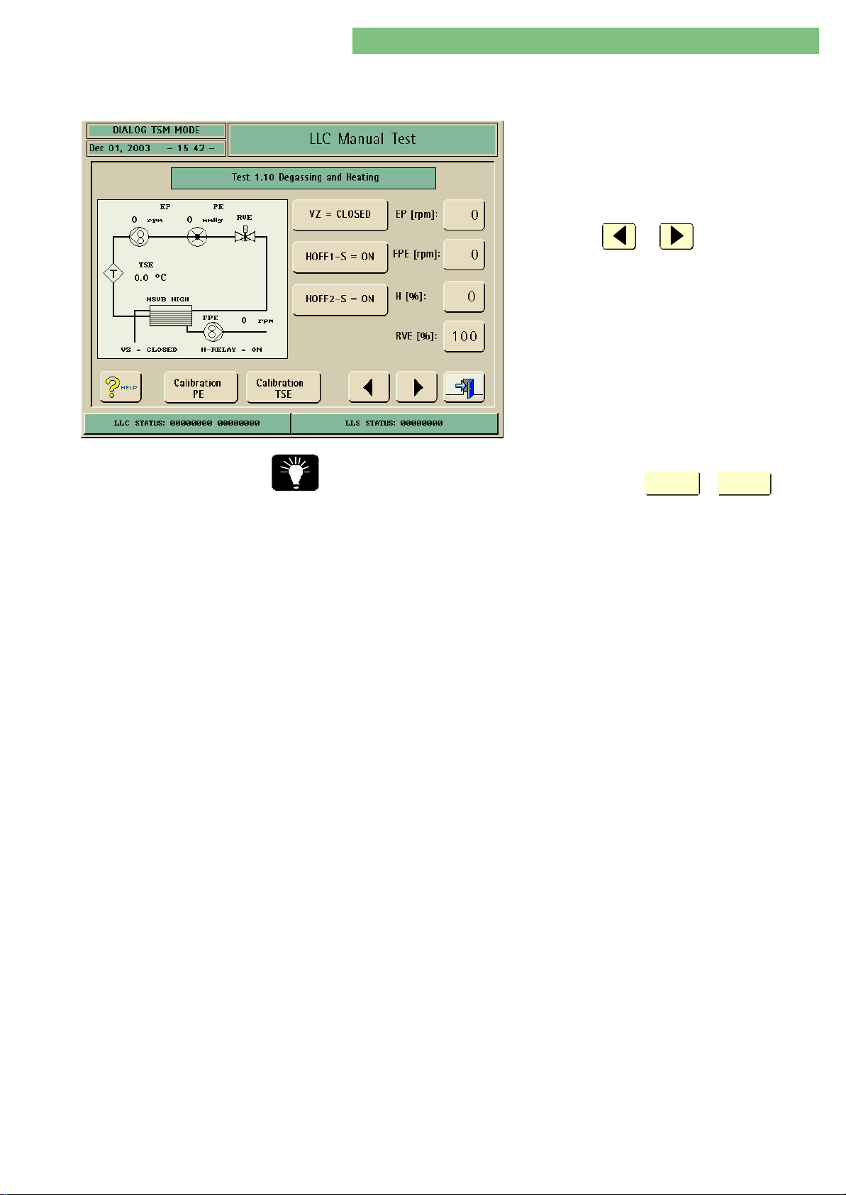
4. TSM Service Program 6/2004 4 73
Dialog/Dialog Advanced
4.10.2.10 Test 1.10 Degassing and
Heating
1. Activate the Degassing and Heating menu with
the Degassing and Heating key in the LLC
Manual Test menu. The following menu is
displayed.
2. Check the functions with the appropriate keys.
3. Press the or key to skip to the
previous or to the next test point.
You can skip directly to the calibration of the pressure sensor PEPE or the
temperature sensor TSETSE by pressing the appropriate
Calibration
PE
or
Calibration
TSE
key.
The components of the degassing and heating circuit can be tested step by step.
All balance chamber valves are switched so that one half of the balance chamber
is open and the other side closed to position the membrane.
The flow pump FPEFPE and FPAFPA have the same speed and work in main flow. If the
speed of FPEFPE is set the degassing pump EPEP starts automatically with a higher
speed.
The heater HH is stopped if the degassing pump EPEP < 500 min-1, the degassing
temperature sensor TSETSE > 89 oC, degassing control valve RVERVE < 30 % or the
upline tank VB is empty.
The degassing pump EPEP must be able to build up a flow of > 1200 ml/min at a
negative pressure of - 400 mmHg.
MT-MD-DE08C M.KAY
DialogAd_sm_Chapter 4-2_6-2004.doc/pdf <120304> ddmmyy
B. Braun Medizintechnologie GmbH
Page 74
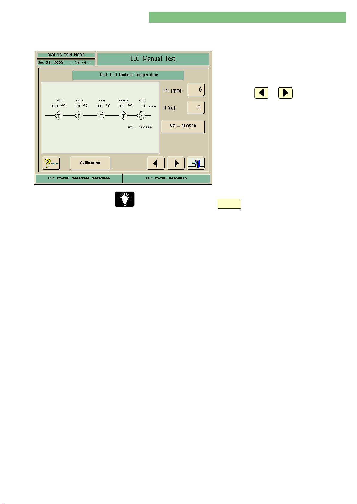
4. TSM Service Program 6/2004 4 74
Dialog/Dialog Advanced
4.10.2.11 Test 1.11 Dialysis
Temperature
1. Activate the Dialysis Temperature menu with
the Dialysis Temperature key in the LLC Manual
Test menu. The following menu is displayed.
2. Check the functions with the appropriate keys.
3. Press the or key to skip to the
previous or to the next test point.
You can skip directly to the calibration of the temperature sensors TSBIC/TSBIC/
TSD/TSD-STSD/TSD-S by pressing the
Calibration
key.
The dialysate is heated up with the set heater power H %H % .
The flow pumps FPE/FPAFPE/FPA work with the set speed. The balance chambers are
opened and the machine works in main flow.
The temperature must be controlled by the heater to a stable set-point to test the
temperature sensors.
If you open the circulation valve ZVZV a closed flow circuit is achieved (via the
upline tank). The flow pump FPEFPE should be set to 1500 min-1.
The temperature sensors must be in the measurement range of + 32 to + 44 oC
with a deviation of > - 1.5 oC and < + 0.5 oC.
The measurement range is as follows:
TSE, TSDTSE, TSD, TSBICTSBIC: 0 to 100 oC
TSD-STSD-S: 30 to 55 oC
MT-MD-DE08C M.KAY
DialogAd_sm_Chapter 4-2_6-2004.doc/pdf <120304> ddmmyy
B. Braun Medizintechnologie GmbH
Page 75
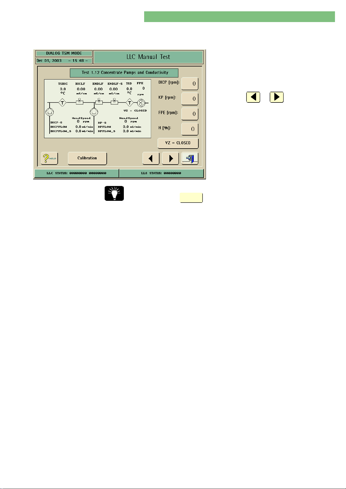
4. TSM Service Program 6/2004 4 75
Dialog/Dialog Advanced
4.10.2.12 Test 1.12 Concentrate
Pumps and Conductivity
1. Activate the Concentrate Pumps and
Conductivity menu with the Concentrate
Pumps and Conductivity key in the LLC Manual
Test menu. The following menu is displayed.
2. Check the functions with the appropriate keys.
3. Press the or key to skip to the
previous or to the next test point.
You can skip directly to the calibration of the conductivity sensors BICLF/ENDLFBICLF/ENDLF
by pressing the
Calibration
key.
You can set the pumps BICP/KPBICP/KP, flow pump FPEFPE and the heater power H %H % .
All balance chamber valves are open and the flow pump FPAFPA works with the
same speed as FPEFPE.
The machine is in main flow. The machine can suck-in concentrate with the
concentrate pumps BICP/KPBICP/KP for the preparation of the conductivity to test the
conductivity sensors BICLF/ENDLF/ENDLF-SBICLF/ENDLF/ENDLF-S.
You can connect a dialysis measurement instrument at the dialyser couplings or
between FPEFPE and the balance chamber.
The supervisor displays the head speed BICP-S/KP-SBICP-S/KP-S of the concentrate pumps.
Set the speed of the flow pump FPEFPE to 1500 min-1. Thereby the pulsating flow of
the pumps have no influence on the conductivity measurement.
MT-MD-DE08C M.KAY
DialogAd_sm_Chapter 4-2_6-2004.doc/pdf <120304> ddmmyy
B. Braun Medizintechnologie GmbH
Page 76
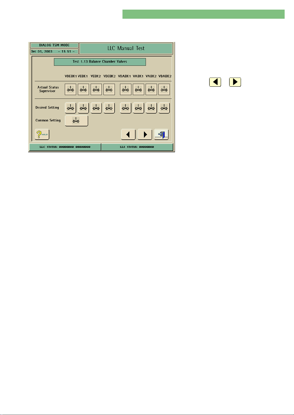
4. TSM Service Program 6/2004 4 76
Dialog/Dialog Advanced
4.10.2.13 Test 1.13 Balance
Chamber Valves
1. Activate the Balance Chamber Valves menu
with the Balance Chamber Valves key in the LLC
Manual Test menu. The following menu is
displayed.
2. Check the functions with the appropriate keys.
3. Press the or key to skip to the
previous or to the next test point.
You can activate a single valve or combined setting via the controller. The actual
condition is displayed by the supervisor. The following valves can be activated:
Valves
VDEBK1/2VDEBK1/2 Dialyser inlet valve balance chamber
VEBK1/2VEBK1/2 Inlet valve balance chamber
VDABK1/2VDABK1/2 Dialyser outlet valve balance chamber
VABK1/2VABK1/2 Outlet valve balance chamber
MT-MD-DE08C M.KAY
DialogAd_sm_Chapter 4-2_6-2004.doc/pdf <120304> ddmmyy
B. Braun Medizintechnologie GmbH
Page 77
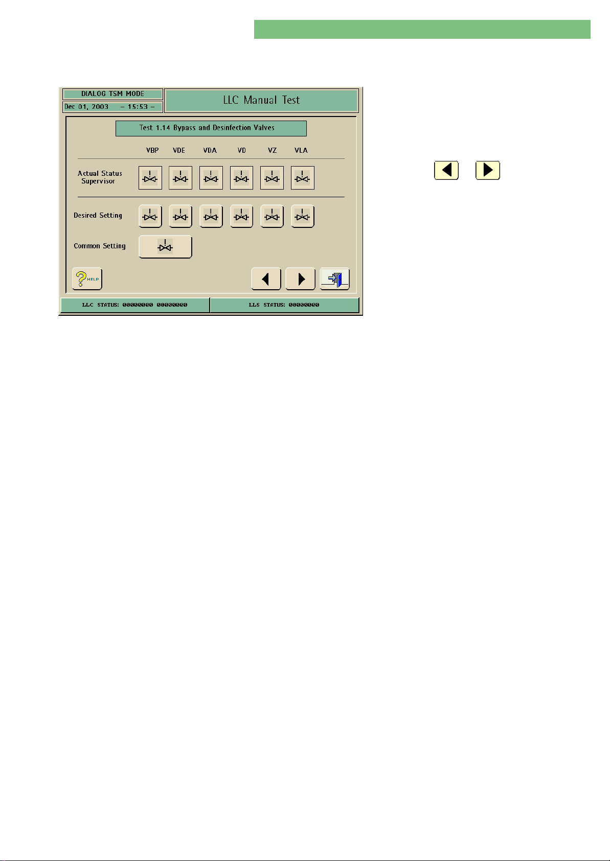
4. TSM Service Program 6/2004 4 77
Dialog/Dialog Advanced
4.10.2.14 Test 1.14 Bypass and
Disinfection Valves
1. Activate the Bypass and Disinfection Valves
menu with the Bypass and Disinfection Valves
key in the LLC Manual Test menu. The following
menu is displayed.
2. Check the functions with the appropriate keys.
3. Press the or key to skip to the
previous or to the next test point.
You can activate a single valve or combined setting via the controller. The actual
condition is displayed by the supervisor. The following valves can be activated:
Valves
VBPVBP Bypass valve
VDEVDE Dialyser inlet valve
VDAVDA Dialyser outlet valve
VDVD Disinfection valve
VZVZ Circulation valve
VLAVLA Ais separator valve
MT-MD-DE08C M.KAY
DialogAd_sm_Chapter 4-2_6-2004.doc/pdf <120304> ddmmyy
B. Braun Medizintechnologie GmbH
Page 78
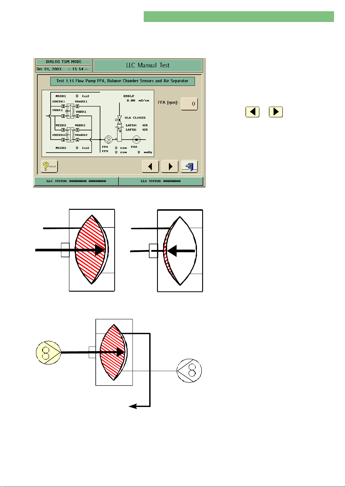
4. TSM Service Program 6/2004 4 78
Dialog/Dialog Advanced
4.10.2.15 Test 1.15 Flow Pump FPA,
Balance Chamber Sensors
and Air Separator
1. Activate the Flow Pump FPA, Balance Chamber
Sensors and Air Separator menu with the Flow
Pump FPA, Balance Chamber Sensors and Air
Separator key in the LLC Manual Test menu. The
following menu is displayed.
2. Check the functions with the appropriate keys.
3. Press the or key to skip to the
previous or to the next test point.
BK
MSBK MSBK
Fig. : Switch Point MSBK1/2
Phase 1Phase 1
FPE
BK
If the test (initialisation) is started the switching
point of the membrane position sensor balance
chambers MSBK1/2MSBK1/2 are detected. If the maximum
stroke of MSBK1/2MSBK1/2 is reached the balance
chamber valves are automatically switched (see
figure).
If you set the flow pump FPAFPA the left side of one of
the balance chambers is filled by the flow pump
FPEFPE. Simultaneously the fluid in the right side of
the balance chamber is emptied to the drain.
FPA
Fig. : Filling Cycle Balance Chamber Phase 1
MT-MD-DE08C M.KAY
DialogAd_sm_Chapter 4-2_6-2004.doc/pdf <120304> ddmmyy
BK
Abfluß
Drain
B. Braun Medizintechnologie GmbH
Page 79
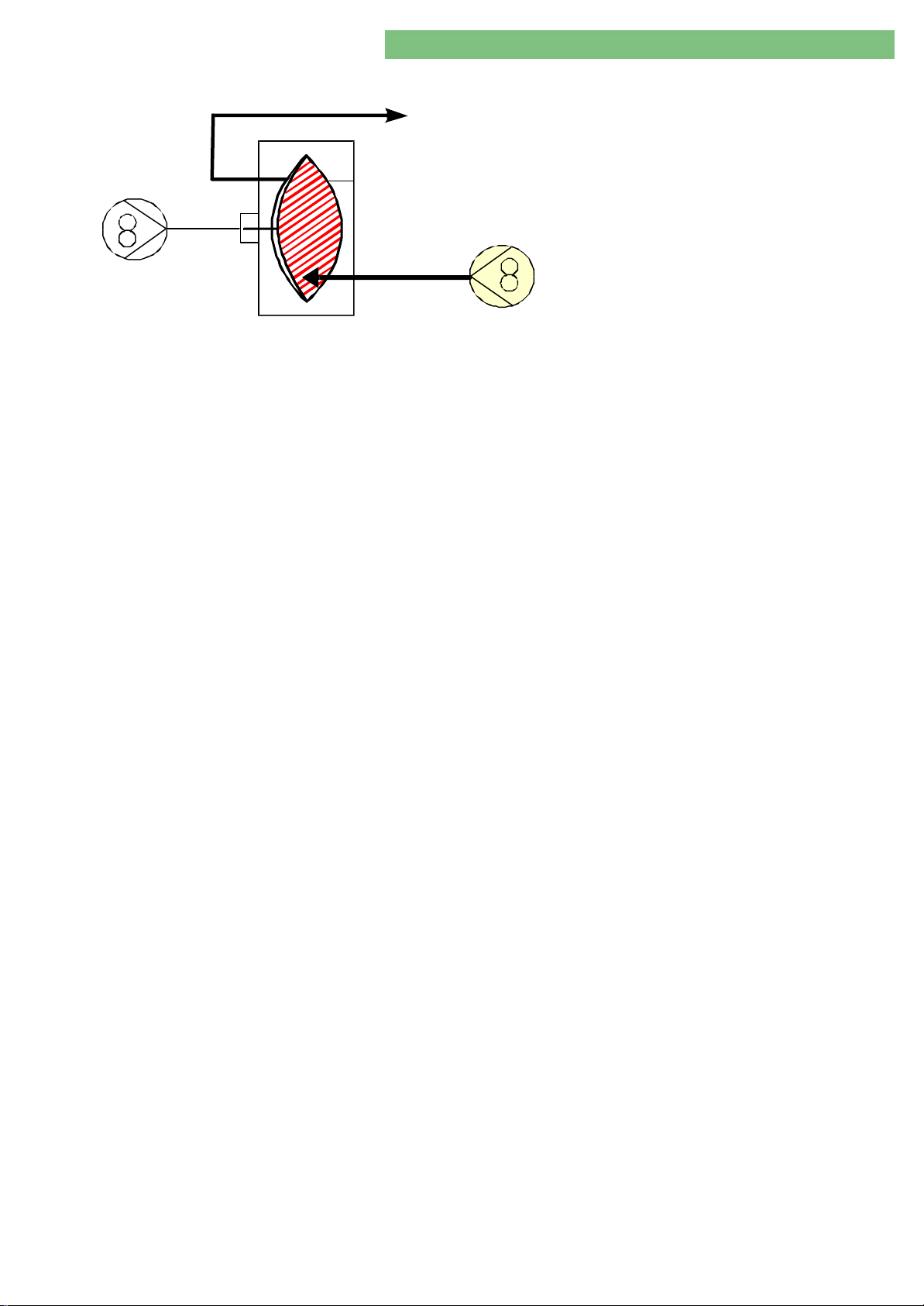
4. TSM Service Program 6/2004 4 79
Dialog/Dialog Advanced
Phase 2Phase 2
FPE
BK
Fig. : Filling Cycle Balance Chamber Phase 2
Dialysator
Dialyser
FPA
The right side of the balance chamber is filled with
the fluid from the dialyser by the flow pump FPAFPA.
Simulataneuosly the fresh fluid in the left side of
the balance chamber is delivered into the dialyser
circuit.
The concentrate pump KPKP is set to a fixed speed of
20 min-1 during this test. Thereby a final
conductivity ENDLFENDLF of > 0.5 mS/cm is obtained if
concentrate is connected.
This conductivity is required to test the level
sensors in the air separator LALA. If the lower level
sensor LAFSULAFSU is activated the air separator valve
VLAVLA is opened and the balance chamber valves are
switched. Thereby FPEFPE delivers fluid into the
dialyser circuit. VLAVLA is only closed and switched to
normal operation if the top level sensor LAFSOLAFSO
detects fluid.
MT-MD-DE08C M.KAY
DialogAd_sm_Chapter 4-2_6-2004.doc/pdf <120304> ddmmyy
B. Braun Medizintechnologie GmbH
Page 80
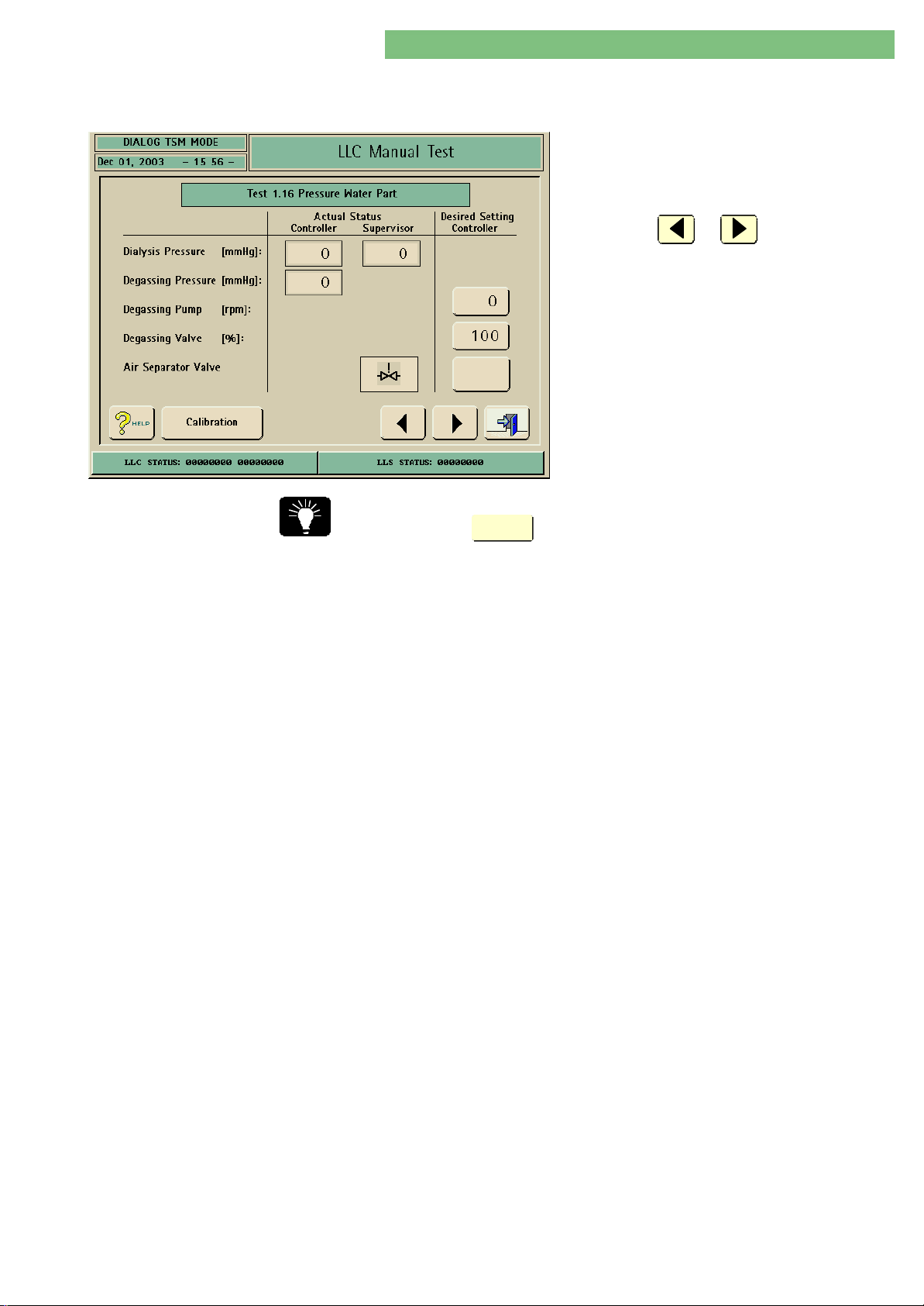
4. TSM Service Program 6/2004 4 80
Dialog/Dialog Advanced
4.10.2.16 Test 1.16 Pressure Water
Part
1. Activate the Pressure Water Part menu with the
Pressure Water Part key in the LLC Manual Test
menu. The following menu is displayed.
2. Check the functions with the appropriate keys.
3. Press the or key to skip to the
previous or to the next test point.
You can skip directly to the calibration of the pressure sensors PE/PDAPE/PDA by
pressing the
Calibration
key.
The degassing pump EPEP and the degassing control valve RVERVE can be set. The air
separator valve VLAVLA can be opened/closed. A negative pressure can be obtained
via the degassing pump PEPE to test the degassing presure sensor PEPE and the outlet
dialysate fluid pressure sensor PDAPDA. If VLAVLA is opened the negative pressure is also
present at PDAPDA. If fluid is in the connection line between the air separator and
degassing circuit the fluid column leads to a higher pressure at PEPE, according to
the level difference.
A dialysis measurement instrument should be connected to the dialyser
couplings for the pressure measurement.
MT-MD-DE08C M.KAY
DialogAd_sm_Chapter 4-2_6-2004.doc/pdf <120304> ddmmyy
B. Braun Medizintechnologie GmbH
Page 81
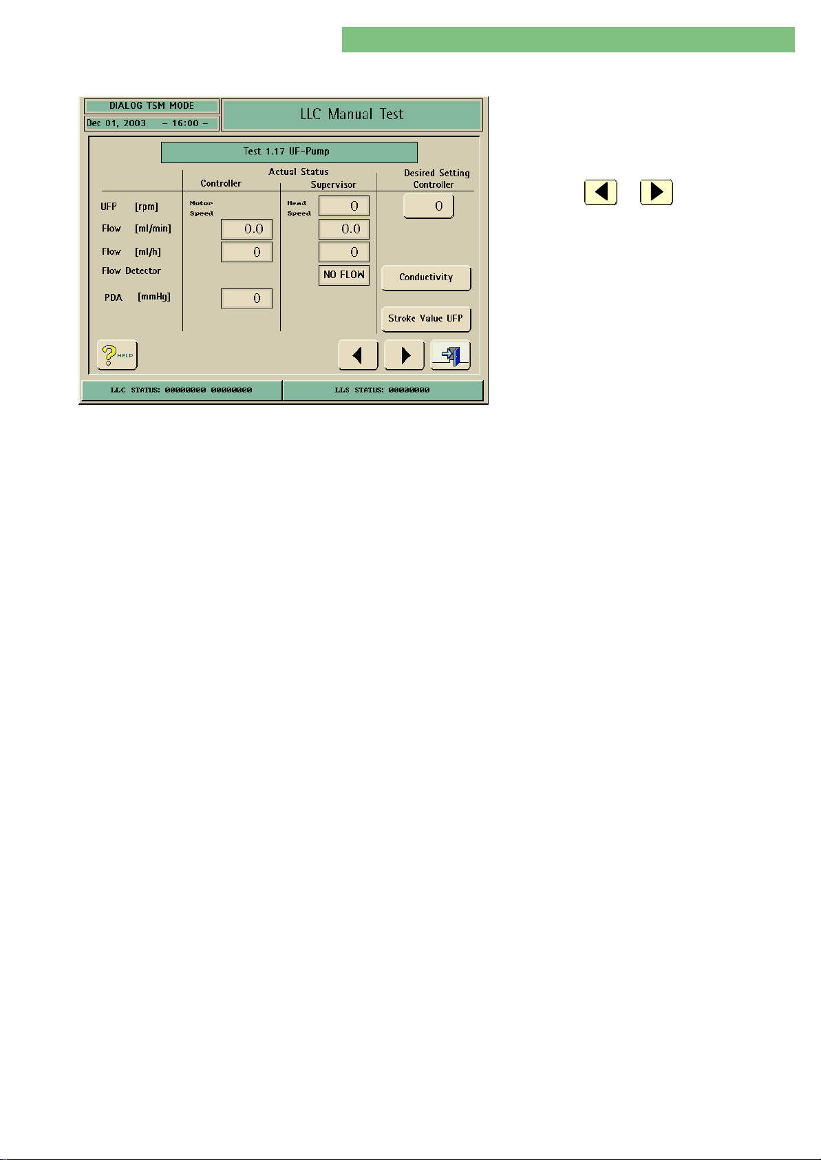
4. TSM Service Program 6/2004 4 81
Dialog/Dialog Advanced
4.10.2.17 Test 1.17 UF Pump
1. Activate the UF-Pump menu with the UF-Pump
key in the LLC Manual Test menu. The following
menu is displayed.
2. Check the functions with the appropriate keys.
3. Press the or key to skip to the
previous or to the next test point.
You can set the speed of the UFUF pump UFPUFP. The head speed and the calculated
flow is displayed. At the beginning of the test the balance chambers are
initialised. The flow pumps FPE/FPAFPE/FPA are activated to reach the prepressure for
UFPUFP, set by the value of the throttle DDEDDE.
The Flow Detector FMFM is only present in machines with the option HDF bag. FMFM
detects a fluid flow if UFPUFP runs.
The Stroke Value UFP should not be used in a normal case, because UFPUFP must be
calibrated (see LLC manual calibration).
MT-MD-DE08C M.KAY
DialogAd_sm_Chapter 4-2_6-2004.doc/pdf <120304> ddmmyy
B. Braun Medizintechnologie GmbH
Page 82
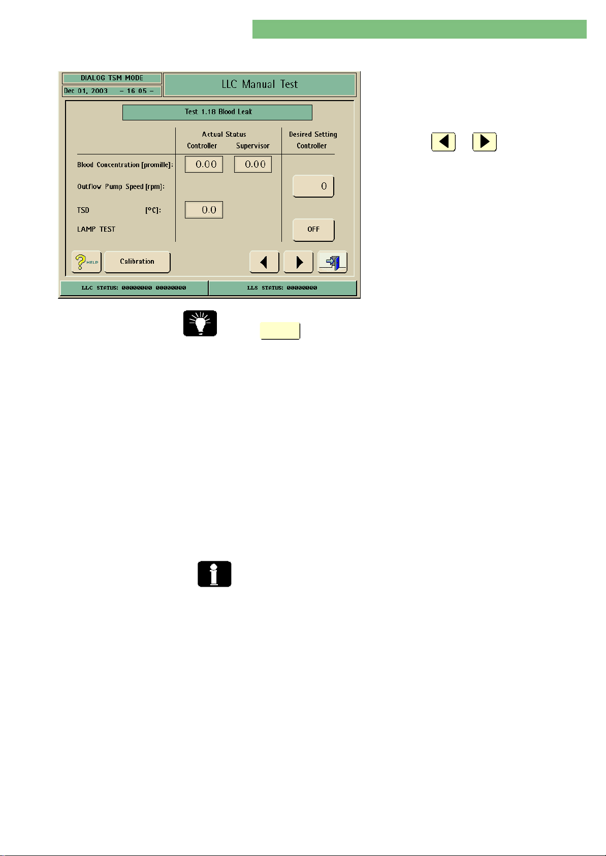
4. TSM Service Program 6/2004 4 82
Dialog/Dialog Advanced
4.10.2.18 Test 1.18 Blood Leak
1. Activate the Blood Leak Detector menu with the
Blood Leak Detector key in the LLC Manual Test
menu. The following menu is displayed.
2. Check the functions with the appropriate keys.
3. Press the or key to skip to the
previous or to the next test point.
You can check the following functions of the blood
leak detector:
• Red and green LED
• Receiver circuit
• Optical efficiency of the detector block
You can skip directly to the calibration of the blood leak detector by pressing the
Calibration
key.
Blood Leak Detector
1 and 2
Blood Leak Detector 2 A Dialog software version number ≥ 3.46 is required for the blood leak detector 2.
The safety air detector type is selected in LLC Manual Calibration , Calibration 2.7
Blood Leak Detector SAD, BL Type:
• No automatic adjustment (type 3810 6515)
• Automatic adjustment in preparation (type 3810 6515)
• BL type 2 with automatic adjustment (type 3824 3784/art. no. 3451 908X)
The blood leak detector 2 performs an automatic calibration of the zero point with
a reference diode.
The blood leak detector 2 can be checked and calibrated. The rinsing block must
have an even temperature for calibration. If both dialyser couplings are
connected to the rinsing bridge the flow pumps (FPAFPA/ FPEFPE) work in main flow.
If only one coupling is connected FPEFPE is stopped. The test solution can be sucked
in by the second coupling via FPAFPA. The first calibation point must be performed
with clean water.
A function test and a calibration is performed for the blood leak detector 2.
If an actual value is out of limits during the function test exchange the blood leak
detector 2.
Check the blood leak detector 2 after a citro-thermal disinfection (LLC Manual
Test, Test 1.18 Blood Leak Detector).
Close front and rear door for the function test to prevent light irradiation on the
sensor.
MT-MD-DE08C M.KAY
DialogAd_sm_Chapter 4-2_6-2004.doc/pdf <120304> ddmmyy
LeakagesLeakages
Air and micro-bubbles can lead to false measurement values in the measurement
line and can cause fluctuation of the actual value.
If air is visible check the complete system for leaks in menu 1.20 Test Water Part.
After the initialisation phase rinse the blood leak detector approx. 1 min and then
perform a leakage test of the system in menu 1.19 Leak Test.
B. Braun Medizintechnologie GmbH
Page 83
4. TSM Service Program 6/2004 4 83
Dialog/Dialog Advanced
Check Blood Leak Detector Type 2 1. Connect both dialyser couplings to the rinsing bridge.
2. Select menu 1.18 in TSM to perform a function check of the blood leak
detector.
3. Rinse the blood leak detector BL for approx. 1 min at the beginning of the
rinsing time with flow pump outlet FPAFPA = 2000 min-1. Thereby possible air
bubbles in the system are removed.
4. Rinse blood leak detector for approx. 15 to 30 min with FPA = 1000 min-1 to
warm up the complete system to a temperature of approx. 40 oC.
5. The LED Test is activated with the LED TEST OFF key. The OFF key switches to
the RED key as soon as the key is pressed.
The red LED is tested after 10 s. The controller value for the switched off red
LED must be as follows (the supervisor value is uncritical):
red LED Actual Status Controller
Blood Concentration
6. Press the LED TEST RED key to switch to the green LED. The RED key switches
to the GREEN key.
The green LED is tested. The controller value for the switched off green LED
must be as follows (the supervisor value is uncritical):
green LED Actual Status Controller
Blood Concentration
< 4.00
> 2.06
7. The actual controller values for the red LED and the green LED must be
divided.
The calculated value must be in the following limits (to the first decimal
digit/round off):
red LED / green LED
1.2 - 1.4
Exchange the blood leak detector type 2 if one of these three values are out of
limits.
Check Blood Leak Detector Type 1 1. The LED Test is activated with the LED TEST OFF key. The OFF key switches to
the RED key when pressed. The blood concentration value for the detector
signal is displayed for approx. 10 s.
The blood concentration value of the controller for the switched off LEDs must
be as follows (the supervisor value is uncritical):
Both LEDs switched off Low Level Controller
Blood Concentration ValueBlood Concentration Value < 0.05
The red LED is automatically activated after 10 s. The controller value for the
switched off red LED must be as follows (the supervisor value is uncritical):
red LEDred LED Low Level ControllerLow Level Controller
Blood Concentration ValueBlood Concentration Value 2.75 to 3.25
2. Press LED TEST RED key, to switch to the green LED. The RED key switches to
the GREEN key.
The green LED is tested. The controller value for the switched off green LED
must be as follows (the supervisor value is uncritical):
green LEDgreen LED Low Level ControllerLow Level Controller
Blood Concentration ValueBlood Concentration Value 2.00 to 2.50
MT-MD-DE08C M.KAY
DialogAd_sm_Chapter 4-2_6-2004.doc/pdf <120304> ddmmyy
If values deviate a calibration may be possible via the potentiometers at the blood
leak detector type 1 (see also low level calibration).
B. Braun Medizintechnologie GmbH
Page 84
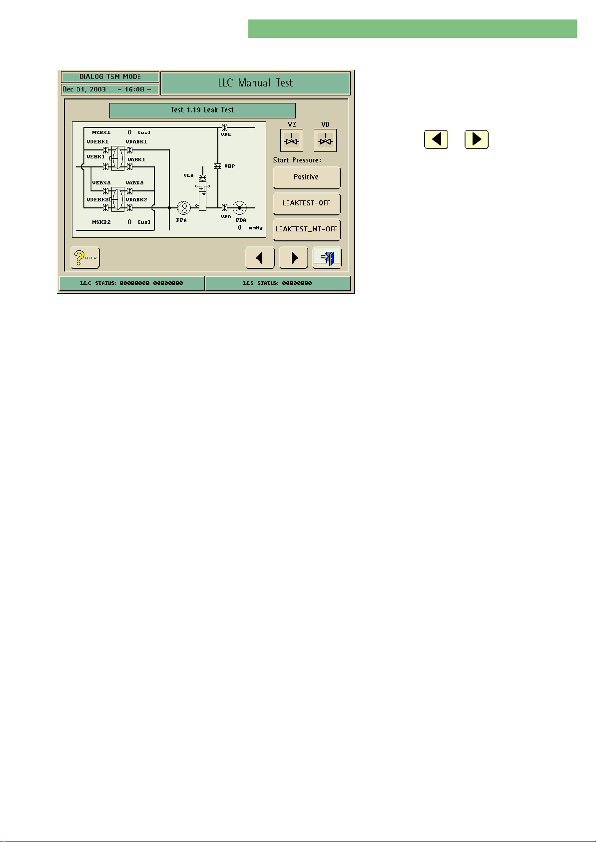
4. TSM Service Program 6/2004 4 84
Dialog/Dialog Advanced
4.10.2.19 Test 1.19 Leak Test
Leak Test
1. Activate the Leak Test menu with the Leak Test
key in the LLC Manual Test menu. The following
menu is displayed.
2. Check the functions with the appropriate keys.
3. Press the or key to skip to the
previous or to the next test point.
You can run a leakage test for the balance chamber
system, the bypass valve VBPVBP and the main flow
valves VDE/VDAVDE/VDA, the air separator valve VLAVLA and
the UF pump UFPUFP. The flow system must be filled
with water prior to the leakage test (if necassary fill
in menu 1.20 Water Part Overview).
The following components are tested:
Start Pressure Positive
Membrane position sensors: MSBK1/2MSBK1/2
Balance chamber valves: VDEBK1/2, VDABK1/2, VEBK1/2,VDEBK1/2, VDABK1/2, VEBK1/2,
VABK1/2VABK1/2
Bypass valve: VBPVBP
Dialyser in/output valves: VDE, VDAVDE, VDA
Disinfection valve: VDVD
Air separator valve: VLAVLA
* Membrane leakproof test: VDEBK/VABKVDEBK/VABK (opened)
VDABK/VEBK/VLAVDABK/VEBK/VLA (closed)
(*If Start Pressure Positive was set: An additional membrane leakproof test is performed
after the second test step.)
If the test is activated for the dialysate circuit an automatic leakage test is
performed. The test is started with a positive test pressure and then followed by a
negative test pressure.
If the test is started with a positive test pressure an additional test step is
performed after the second test step. This additional step performs a leakproof test
of the membranes. The valves have the following position during the test:
• VDEBK/VABKVDEBK/VABK: opened
• VDABK/VEBK/VLAVDABK/VEBK/VLA: closed
The test pressure is present in the inlet balance chamber during this test. The
membrane seals the outlet of the test circuit. A defective membrane would cause
a pressure drop.
HDF OnlineHDF Online
HDF online machines: the two additional test steps 2a2a and 2b2b are performed
after the membrane test. Thus the valves VDFFVDFF, VSBVSB, VSAEVSAE and VSAAVSAA and the
substitution port are checked.
MT-MD-DE08C M.KAY
DialogAd_sm_Chapter 4-2_6-2004.doc/pdf <120304> ddmmyy
Start Pressure Negative
LLC Alarm
If the test is activated for the dialysate circuit an automatic leakage test is
performed. The test is started with a negative test pressure and then followed by a
positive test pressure.
The leakage test consists of three test steps. If an error occurs an LLC alarm is
activated (LLC Status 00020000).
B. Braun Medizintechnologie GmbH
Page 85
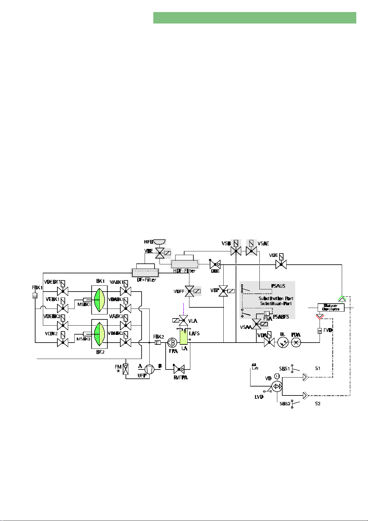
4. TSM Service Program 6/2004 4 85
Dialog/Dialog Advanced
Test Procedure Positive Test Pressure • A positive pressure is built up with the FPEFPE pump.
• The pump is stopped and the valves closed if the set-point pressure for PDAPDA =
+400 mmHg is reached.
• The PDAPDA reference value is stored after a wait state of 5 s.
• This reference value is compared with the actual value after 30 s.
• If the deviation is < 10 mmHg the next test step is performed.
Test Step 1
Test Step 2
Test Step 2a NoteNote
Test Step 2b
VLAVLA, VEBK1/2,VEBK1/2, VABK1/2VABK1/2 ------------------------------ closed
VLA, VDEBK1/2, VDABK1/2VLA, VDEBK1/2, VDABK1/2 ------------------------ closed
NoteNote
Only if start pressure was positiveOnly if start pressure was positive
After the second test step a leakproof test of the membranes is performed. The
valves have the following position:
VDEBK/VABKVDEBK/VABK: ------------------------------ opened
VDABK/VEBK/VLAVDABK/VEBK/VLA:------------------------- closed
Test step 2a and 2b only for HDF online machines.Test step 2a and 2b only for HDF online machines.
VLA VLA Air separator valve: --------------------- closed
VDFFVDFF DF filter valve: ------------------------ closed
VSBVSB Substitution bypass valve: -------------- closed
VSAEVSAE Substitution connection inlet valve: --- closed
VLAVLA Air separator valve: --------------------- closed
VDFFVDFF DF filter valve : ------------------------ closed
VSBVSB Substitution bypass valve: -------------- closed
VSAAVSAA Substitution connection outlet valve: - closed
Fig.: Excerpt Flow Diagram for HDF Online
MT-MD-DE08C M.KAY
DialogAd_sm_Chapter 4-2_6-2004.doc/pdf <120304> ddmmyy
Test Step 3
VLAVLA, VDE, VDAVDE, VDA -------------------------------------------------- closed
B. Braun Medizintechnologie GmbH
Page 86

4. TSM Service Program 6/2004 4 86
Dialog/Dialog Advanced
Negative Test Pressure
Test Steps 1 to 3
Leak Test Heat ExchangerLeak Test Heat Exchanger
Manual Leakage Test
Heat Exchanger (WT)
The valve switching is identical with the above description.
• Negative pressure is built up with the UF pump after the third test step.
• The pump is stopped and the valves are closed if the set-point pressure for
PDAPDA = - 400 mmHg is reached.
• The PDAPDA reference value is stored after a wait state of 5 s.
• This reference value is compared with the actual value after 30 s.
• If the deviation is < 10 mmHg the next test step is performed.
The following component is tested:
Heat Exchanger: WTWT
a) Rinse the flow circuit with water prior to the leakage test, to prevent air
bubbles in the test area.
b) Close all valves in the Dialog (switch off machine).
c) Connect a manometer and a syringe filled with water to the water outlet.
d) Build up a test pressure 400 mmHg (+ 50 mmHg) with the syringe and close
with tubing clamp.
e) Check pressure drop. The pressure drop must be < 50 mmHg ín 30 s.
Leak Test Heat Exchanger (WT)
a) Rinse water circuit to prevent air bubbles.
b) Close the outlet.
c) Activate test.
The FPEFPE builds up a pressure.
d) Check pressure drop. The pressure drop must be < 50 mmHg ín 30 s.
MT-MD-DE08C M.KAY
DialogAd_sm_Chapter 4-2_6-2004.doc/pdf <120304> ddmmyy
B. Braun Medizintechnologie GmbH
Page 87
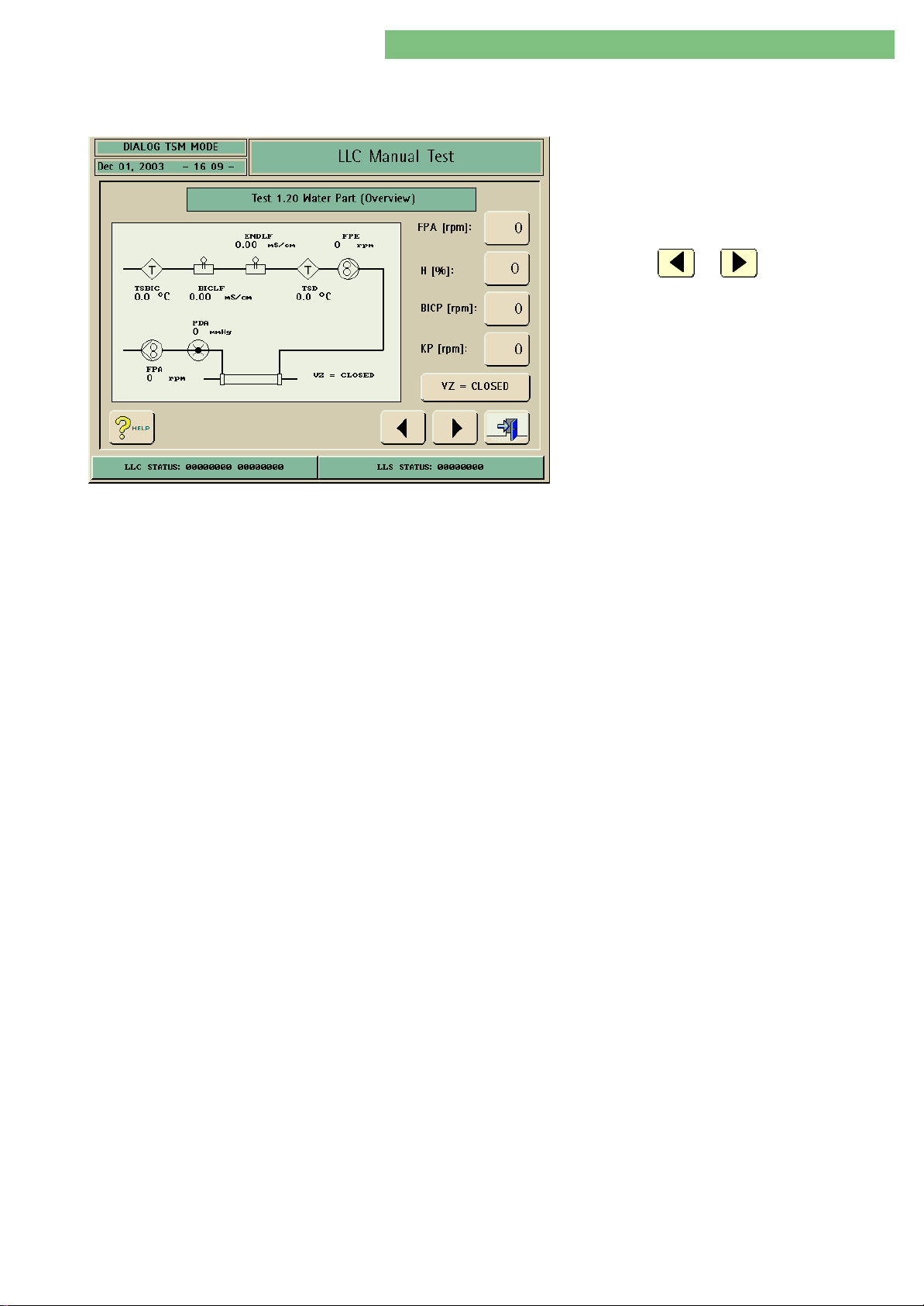
4. TSM Service Program 6/2004 4 87
Dialog/Dialog Advanced
4.10.2.20 Test 1.20 Water Part
(Overview)
1. Activate the Water Part (Overview) menu with
the Water Part (Overview) key in the LLC
Manual Test menu. The following menu is
displayed.
2. Check the functions with the appropriate keys.
3. Press the or key to skip to the
previous or to the next test point.
You can set the speed for the flow pump FPE/FPAFPE/FPA. The heater power H %H % can be
set in %. The speed of the concentrate pumps BICP/KPBICP/KP can be set manually.
After starting this menu the balance chamber is intialised. Then the flow pump
FPEFPE is set to the same speed as FPAFPA. The balance chamber valves are switched
automatically.
MT-MD-DE08C M.KAY
DialogAd_sm_Chapter 4-2_6-2004.doc/pdf <120304> ddmmyy
B. Braun Medizintechnologie GmbH
Page 88
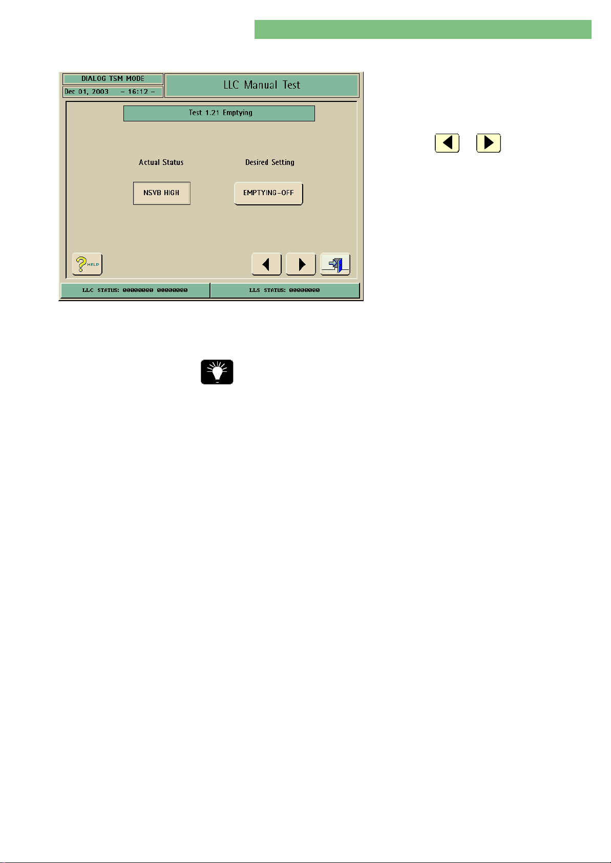
4. TSM Service Program 6/2004 4 88
Dialog/Dialog Advanced
4.10.2.21 Test 1.21 Emptying
1. Activate the Emptying menu with the Emptying
key in the LLC Manual Test menu. The following
menu is displayed.
2. Check the functions with the appropriate keys.
3. Press the or key to skip to the
previous or to the next test point.
You can drain the system. After the emptying key is activated the drain
procedure is started. The actual value, i.e. the fluid level of the upline tank VBVB is
displayed by the level sensors NSVBNSVB.
Start the Emptying ON at least three times and manually clamp the bypass
(tubing) to ensure a complete emptying.
MT-MD-DE08C M.KAY
DialogAd_sm_Chapter 4-2_6-2004.doc/pdf <120304> ddmmyy
B. Braun Medizintechnologie GmbH
Page 89
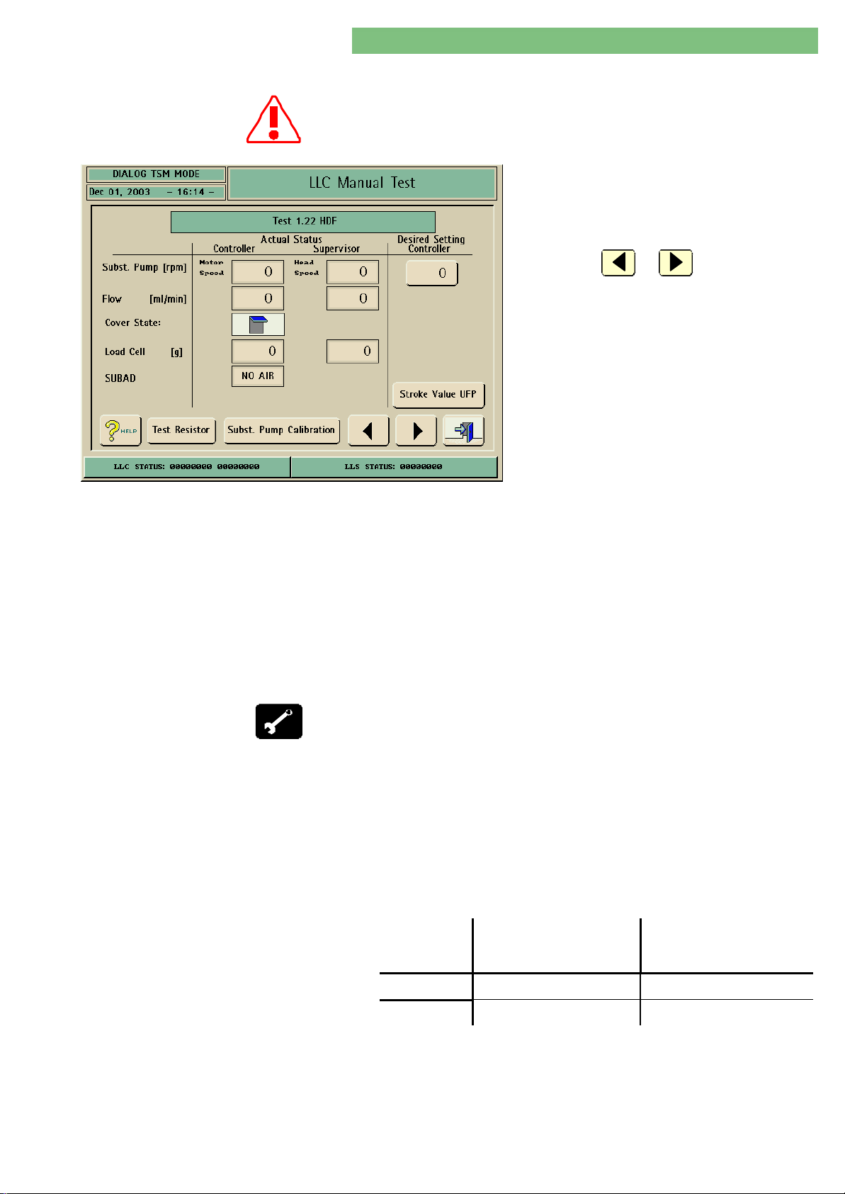
4. TSM Service Program 6/2004 4 89
Dialog/Dialog Advanced
4.10.2.22 Test 1.22 HDF
A max. of 20 kg can be loaded on the HDF arm. This guarantees a safe tilt
stability of the Dialog (see operating instructions)!
1. Activate the HDF menu with the HDF key in the
LLC Manual Test menu. The following menu is
displayed.
2. Check the functions with the appropriate keys.
3. Press the or key to skip to the
previous or to the next test point.
4. Hang the calibration weight on the load cell and
check the Load Cell display ( ± 50 g).
5. Check substitution air detector SUBADSUBAD) for AIR
and NO AIR.
NO AIR
• Insert the substitution line (segment filled
with water) into the SUBADSUBAD and check:
Close SUBADSUBAD cover: NO AIR
AIR
• Insert substitution line (segment with air)
into the SUBADSUBAD and check:
Close SUBADSUBAD cover: AIR
You can test the substitution delivery and the components by connecting a
substitution line. The substitution pump BPVBPV works with the selected speed
(conversion factor between motor speed and head speed: 46.615).
The load cell can be checked after calibration with a calibration weight.
The pump is stopped if the pump cover (cover sensor) is opened.
The flow and the weight loss on the load cell can be checked by using a
graduated cylinder.
The substitution air detector SUBADSUBAD can be checked.
Calibration weight (10 kg)
Substitution Line
6. Open pump cover. Pump stops and opened pump cover symbol is displayed.
7. Insert new pump segment of a new substitution line. Enter the following
speeds and check in the display:
1500 min-1 and 120 min
The speed value ranges are listed in the table.
Enter 1500 min-1 and wait until a stable value is displayed.
Enter 120 min-1 and wait until a stable value is displayed.
SpeedSpeed Actual SatutusActual Satutus
-1
ControllerController
(Motor Speed)(Motor Speed)
Actual SatutusActual Satutus
SupervisorSupervisor
(Head Speed)(Head Speed)
MT-MD-DE08C M.KAY
DialogAd_sm_Chapter 4-2_6-2004.doc/pdf <120304> ddmmyy
15001500 975 - 2025 24 - 51
120120 78 - 162 2 - 4
B. Braun Medizintechnologie GmbH
Page 90
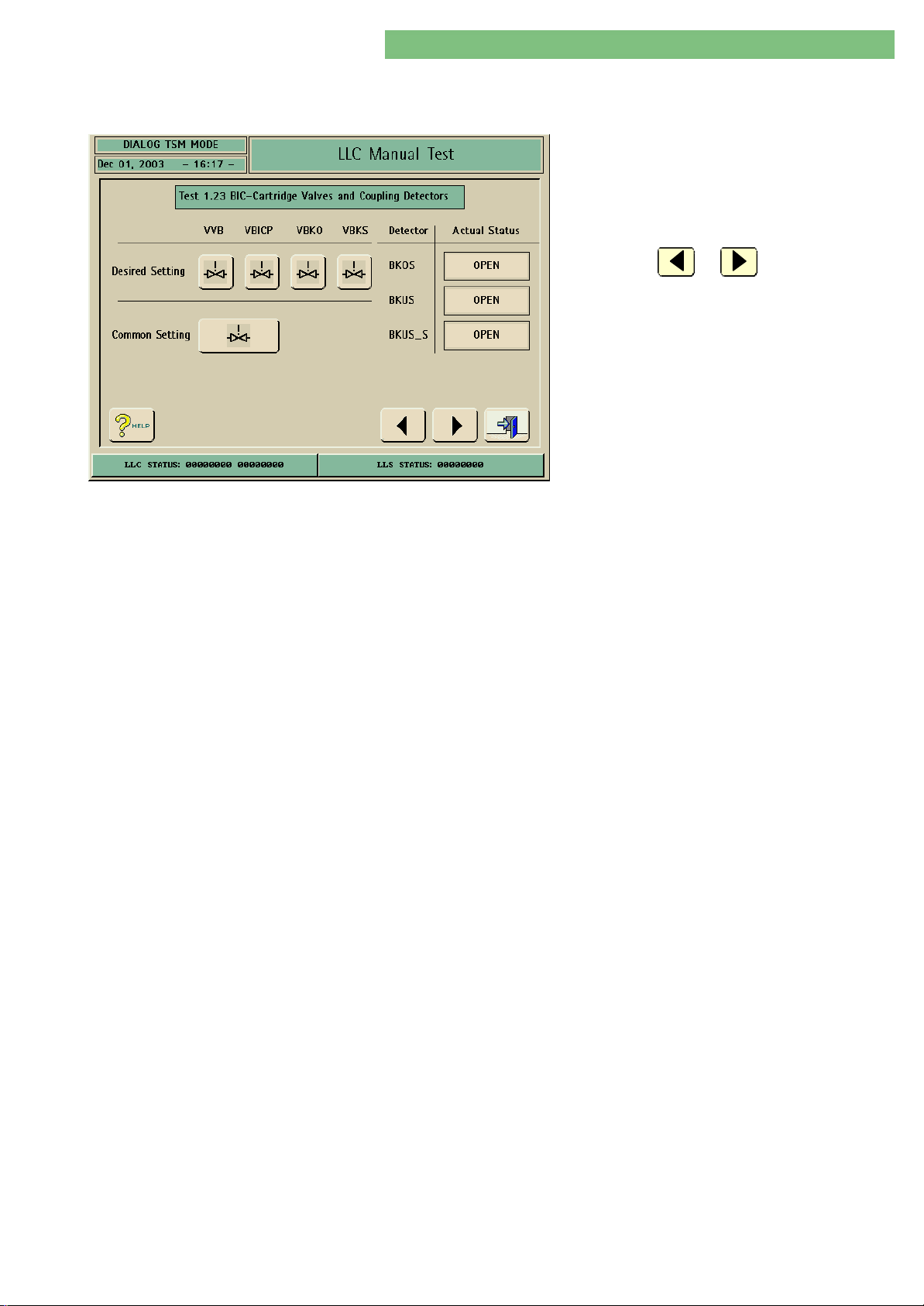
4. TSM Service Program 6/2004 4 90
Dialog/Dialog Advanced
4.10.2.23 1.23 BIC Cartridge Valves
and Coupling Detectors
Valves
1. Activate the BIC Cartridge Valves and Coupling
Detectors menu with the BIC Cartridge Valves
and Coupling Detectors key in the LLC Manual
Test menu. The following menu is displayed.
2. Check the functions with the appropriate keys.
3. Press the or key to skip to the
previous or to the next test point.
VVB, VBICP, VBKO, VBKS
The valves VVBVVB, VBICPVBICP, VBKOVBKO and VBKSVBKS can be switched either separately or
together.
Detectors
BKOS
BIC Cartridge Holder with Nonreturn Valve:
A reed sensor is not present.
BIC Cartridge Holder without Valve:
The status of the reed sensor (OPEN/CLOSED) is displayed.
BKUS, BKUS_S
The status of the reed sensor (OPEN/CLOSED) is displayed.
MT-MD-DE08C M.KAY
DialogAd_sm_Chapter 4-2_6-2004.doc/pdf <120304> ddmmyy
B. Braun Medizintechnologie GmbH
Page 91
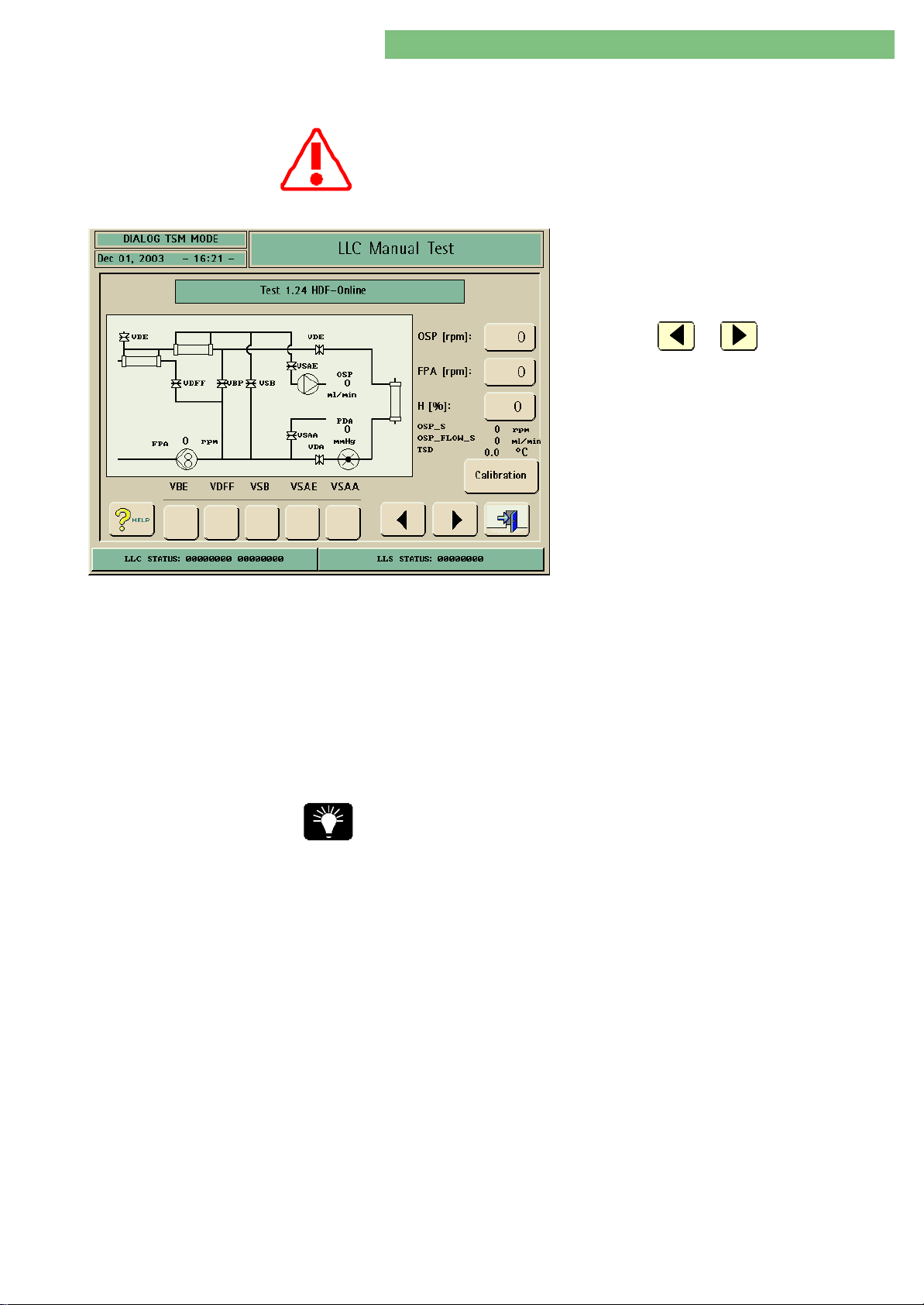
4. TSM Service Program 6/2004 4 91
Dialog/Dialog Advanced
4.10.2.24 1.24 HDF Online
Exchange Intervals:
The HFB filter must be exchanged in one year intervals!
1. Activate the HDF Online menu with the HDF
Online key in the LLC Manual Test menu. The
following menu is displayed.
2. Check the functions with the appropriate keys.
3. Press the or key to skip to the
previous or to the next test point.
Online Substitution Pump
OSP (BPV)
Valves
You can check the function of the HDF online substitution pump OSP (BPV) and
the additional valves.
The function of the HDF online substitution pump OSP (BPV) can be checked.
VBE, VDFF, VSB, VSAE, VSAA
The flow path through both filters (DFDF and HDFHDF ) can be set via the valves.
Before operation in main flow the DF filter inlet must be vented via VDFFVDFF,
because the membranes of the DFDF filter and HDFHDF filter are impermeable to air.
Valve VBEVBE can only be opened if PDAPDA < -100 mmHg to prevent fluid penetration.
Start the Emptying ON at least three times and manually clamp the bypass
(tubing) to ensure a complete emptying.
MT-MD-DE08C M.KAY
DialogAd_sm_Chapter 4-2_6-2004.doc/pdf <120304> ddmmyy
B. Braun Medizintechnologie GmbH
Page 92
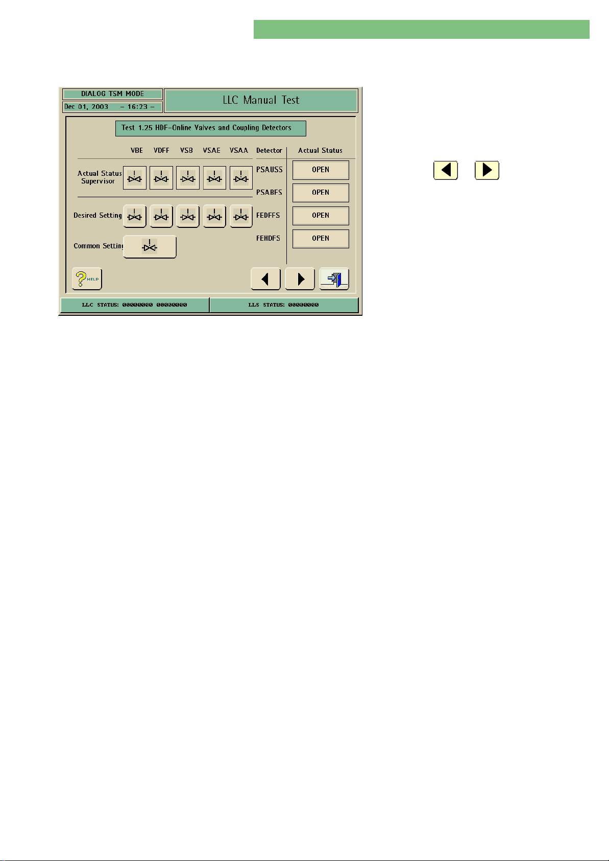
4. TSM Service Program 6/2004 4 92
Dialog/Dialog Advanced
4.10.2.25 1.25 HDF Online Valves
and Coupling Detectors
1. Activate the HDF Online Valves and Coupling
Detectors menu with the HDF Online Valves and
Coupling Detectors key in the LLC Manual Test
menu. The following menu is displayed.
2. Check the functions with the appropriate keys.
3. Press the or key to skip to the
previous or to the next test point.
You can activate and deactivate the HDF online valves.
Valves
Detectors
VBE, VDFF, VSB, VSAE, VSAA
You can either activate or deactivate a single valve with the Desired Setting icon
or all valves VBE, VDFF, VSB, VSAE, VSAA with the Common Setting icon. Thus the
feedback from the LLS can be checked.
PSAUSS (substitution port outlet sensor)
The status of the additional coupling sensor PSAUS can be checked.
PSABFS (substitution port drain sensor)
The status of the additional coupling sensor PSABFS can be checked.
FEDFFS (filter recognition DF filter)
The status of the additional coupling sensor FEDFFS can be checked.
FEHDFS (filter recognition HDF filter)
The status of the additional coupling sensor FEHDFS can be checked.
MT-MD-DE08C M.KAY
DialogAd_sm_Chapter 4-2_6-2004.doc/pdf <120304> ddmmyy
B. Braun Medizintechnologie GmbH
Page 93
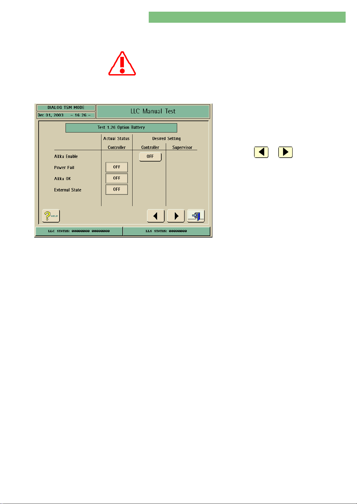
4. TSM Service Program 6/2004 4 93
Dialog/Dialog Advanced
4.10.2.26 1.26 Option Rechargeable
Battery
Charge Batteries
To guarantee battery operation the batteries may have to be charged for
several hours if the Dialog was not connected to mains for a longer period.
If the batteries are empty the charge time is > 8 hours to guarantee a
battery running time of at least 20 minutes.
1. Activate the Option (Rechargeable) Battery
menu with the Option (Rechargeable) Battery
key in the LLC Manual Test menu. The following
menu is displayed.
2. Check the functions with the appropriate keys.
3. Press the or key to skip to the
previous or to the next test point.
The enable parameter can be set and the following
parameters can be checked:
SettingSetting
• Akku Enable (battery enable, AKKU_EN signal)
Akku Enable
(Battery Enable)
Power Fail
CheckCheck
• Power Fail (PF signal)
• Akku OK (battery OK, AKKU_OK signal)
• External State (EXT_STATE signal)
The enable signal is set to ON by the LLC in therapy. Thus indicating to the power
supply that the battery operation can be enabled in the case of a power
breakdown. In all other operating modes (with the exception of therapy) the Akku
Enable (battery enable, AKKU_EN signal) is set to OFF, i.e. the machine is
switched off in case of a power breakdown.
1. Battery loaded (charge LED off), i.e. Akku OK (battery OK) = ON
2. Set Akku Enable (battery enable) to ON.
3. Disconnect machine from mains with mains plug.
An audible signal is activated from the power supply, which indicates that the
machine is running in battery operation.
• Blood pump(s) run(s)
• Monitor is on
• Power Fail = ON
• Akku OK (battery OK) changes from ON to OFF
The switch mode power supply sends the signal to the LLC indicating a power
failure.
OFF Mains voltage present (and in the tolerance limits)
ON Mains voltage not present (or out of tolerance limits)
MT-MD-DE08C M.KAY
DialogAd_sm_Chapter 4-2_6-2004.doc/pdf <120304> ddmmyy
Akku OK
(Battery OK)
External State
ON Battery capacity ≥ required capacity for 20 minutes battery running
time
OFF Battery capacity < required capacity for 20 minutes battery running
time
Indicates if machine was switched on externally.
ON Machine was switched on externally
B. Braun Medizintechnologie GmbH
Page 94
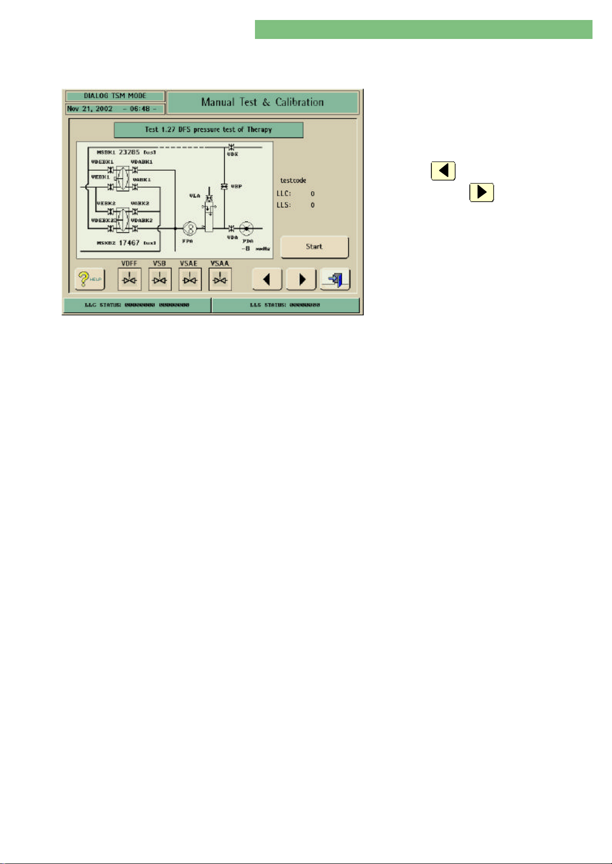
4. TSM Service Program 6/2004 4 94
Dialog/Dialog Advanced
4.10.2.27 1.27 DFS Pressure Test of
Therapy
Start Button
1. Activate the DFS Pressure Test of Therapy menu
with the DFS Pressure Test of Therapy key in the
LLC Manual Test menu. The following menu is
displayed.
2. Check the functions with the appropriate keys.
3. Press the key to skip to the previous test
point or press the key to automatically
skip to the first test point.
You can activate the DFS pressure test with the Start button from the selftest in
Preparation.
Stop Button
Test Code
The test run can be terminated with the Stop button. The button jumps back to
Start in case of an error or at the end of the pressure test.
The test codes for LLC and LLS are displayed for all test phases. In case of an error
the defective components can be determined with the help of the test
description.
MT-MD-DE08C M.KAY
DialogAd_sm_Chapter 4-2_6-2004.doc/pdf <120304> ddmmyy
B. Braun Medizintechnologie GmbH
Page 95
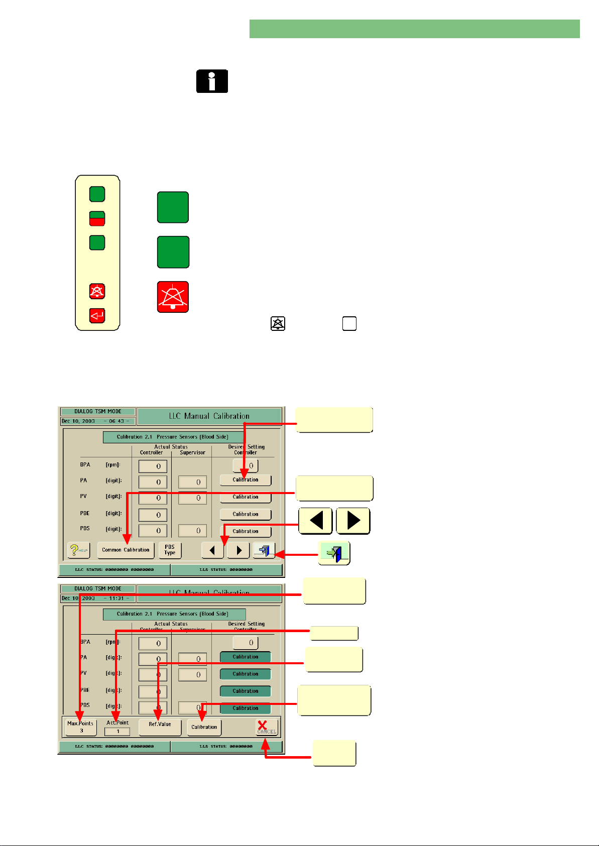
4. TSM Service Program 6/2004 4 95
Dialog/Dialog Advanced
4.10.3 General Information Calibration
Measurement instruments (e.g. dialysis measurement instrument) used to
calibrate Dialog machines are subject to regular inspections or if necessary
calibration by the acc. manufacturer or by a certified calibration lab.
Various keys (software keys and hardware keys) are used during calibration. The
function and significance of the keys are as follows.
Hardware Keys
+
START
STOP
-
Fig. : Keyboard Membrane
+
-
The hardware keys are on the keyboard membrane of the colour monitor (see
figure).
Input values can be increased in increments with the displayed hardware key as
an alternative to the software key on the touch screen.
Input values can be decreased in increments with the displayed hardware key as
an alternative to the software key on the touch screen.
The service overview can be selected in the TSM with the hardware key.
NoteNote
SW SW ≥≥ 3.46 3.46 SW < 3.46SW < 3.46
AQ
Software Keys
The software keys are displayed in the respective menus of the TSM service
program and can be operated via the touch screen.
Calibration
Common Calibration
Max.Points
X
Act.Point
X
Ref.Value
A single sensor is selected for calibration with
the software key and a lower calibration
window is opened.
A combined sensor calibration can be selected
with the software key and a lower calibration
window is opened.
The previous calibration menu or the next
calibration menu can be selected with the
software keys.
Exit the menu with the door key.
The number of calibration steps is displayed or
can be modified.
The current calibration step is displayed.
The input window is opened to enter a reference
value. It should always be close to the proposed
reference value.
MT-MD-DE08C M.KAY
DialogAd_sm_Chapter 4-3_6-2004.doc/pdf <120304> ddmmyy
Calibration
û
CANCEL
The calibration for the respective current
calibration point is started.
A calibration can be terminated. The procedure
is not saved.
B. Braun Medizintechnologie GmbH
Page 96
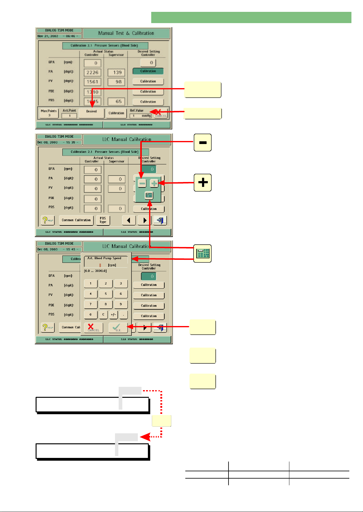
4. TSM Service Program 6/2004 4 96
Dialog/Dialog Advanced
Desired
Value
Ref.Value
X
Dialog software version ≥ 6.20: a dialysis
measurement instrument (e.g. HDM ≥ 99 with a
software version ≥ 3.52) can be connected to
the Dialog to calibrate the pressure, the
temperature and the conductivity. The HDM is
connected to the RS 232 interface of the
motherboard.
The desired value of the machine is displayed.
If a dialysis measurement instrument (HDM) is
connected the referenz value window appears.
The reference value of the dialysis
measurement instrument is displayed.
Input values can be increased in increments
with the displayed software key as an
alternative to the hardware key on the keyboard
membrane of the colour monitor.
Input values can be decreased in increments
with the displayed software key as an
alternative to the hardware key on the keyboard
membrane of the colour monitor.
Terminate Calibration Procedure
Save Calibration Procedure
LLC STATUS: 00000000 00000000
LLS STATUS: 00000000
Conversion Table Voltage/Digits
MT-MD-DE08C M.KAY
DialogAd_sm_Chapter 4-3_6-2004.doc/pdf <120304> ddmmyy
0-1-0
0-1-0
üO.K.
The calculator symbol opens a numeric software
keyboard. You can enter values with this
keyboard. The entered value must be in the
permissible limits (e.g. 0 to 3000, see figure).
An input can be acknowledged, e.g. a reference
value or a completed calibration procedure can
be acknowledged and saved.
O.K.
ü
A calibration procedure can be terminated at
û
CANCEL
O.K.
ü
VoltageVoltage 0 to 5 V 0 to 5 V
DigitsDigits 0 to 4095 0 to 255
any time with the CANCEL key. The existing
calibration data are maintained in the LLS and
LLC.
The calibration procedure is completed and the
new calibration data is stored in the LLC and LLS
with the OK key.
NoteNote
Pay attention to the LLC and LLS status windows.
The bit sequence 0-1-0 must be identical in
the LLC and LLS status windows during the saving
procedure. The calibration data is saved only after
the bit sequence 0-1-0 (see figure).
You should save the calibration data to the hard
disk drive before you exit the TSM service program:
TSM Main Menu, File Operations, Save Calibration
Data.
Controller (12 bit)Controller (12 bit) Supervisor (8 bit)Supervisor (8 bit)
B. Braun Medizintechnologie GmbH
Page 97
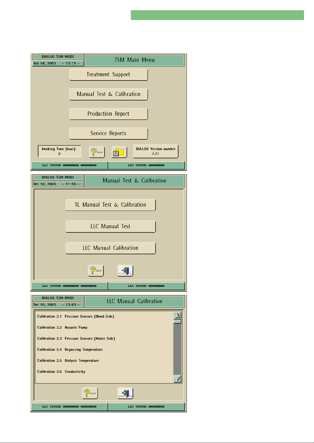
4. TSM Service Program 6/2004 4 97
Dialog/Dialog Advanced
4.10.4 Low Level Calibration
You can calibrate all sensors in the LLC Manual Calibration menu. The number of
calibration points is preset but can be changed manually if a higher accuracy
/linearity is wanted.
Some sensors have the possibility to run a
combined or a single calibration.
The TSM Main Menu is diplayed after the machine
is switched on (service switch in position 2).
1. Activate the Manual Test & Calibration menu
with the Manual Test & Calibration key in the
TSM Main Menu. The following menu is
displayed.
2. Activate the LLC Manual Calibration menu with
the LLC Manual Calibration key in the Manual
Test and Calibration menu. The following menu
is displayed.
The following low level calibrations can be selected:
• 2.1 Pressure sensors (blood side)
• 2.2 Heparin pump
• 2.3 Pressure sensors (water side)
• 2.4 Degassing temperature
• 2.5 Dialysis temperature
• 2.6 Conductivity
• 2.7 Blood leak detector
• 2.8 Flow of BICP, KP and UF pump
• 2.9 Safety air detector SAD
• 2.10 BICLF ratio and ENDLF ratio
• 2.11 Load cell
• 2.12 PV alarm window
• 2.13 Flow rate of BPA and BPV
• 2.14 Substitution pump
• 2.15 HDF online substitution pump OSP
MT-MD-DE08C M.KAY
DialogAd_sm_Chapter 4-3_6-2004.doc/pdf <120304> ddmmyy
B. Braun Medizintechnologie GmbH
Page 98
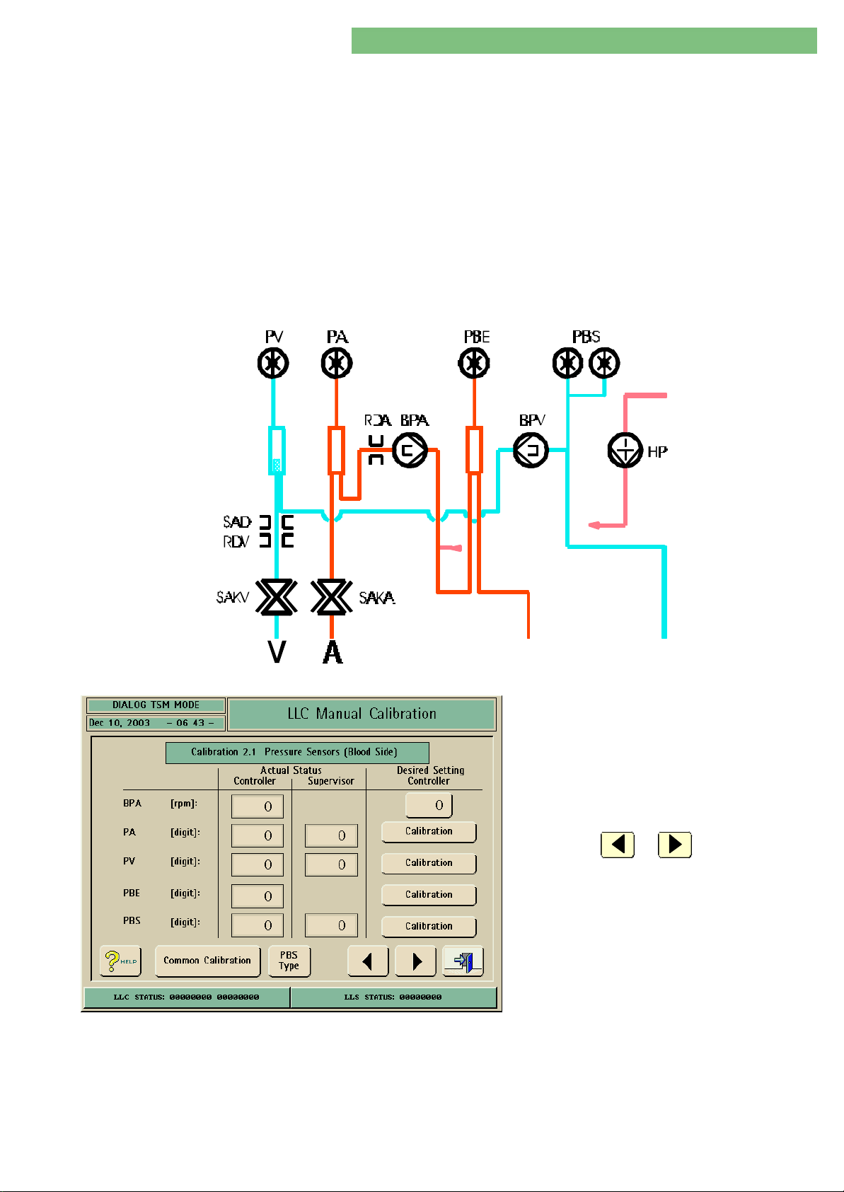
4. TSM Service Program 6/2004 4 98
Dialog/Dialog Advanced
4.10.4.1 Calibration Pressure Sensors
Blood Side PA, PV, PBE and PBS
Prior to Calibration • Use calibrated dialysis measurement instrument
• Wait until Dialog has reached working temperature
You can calibrate the following pressure sensors of the blood side either
separately or combined:
• PAPA arterial pressure sensor
• PVPV venous pressure sensor
• PBEPBE blood inlet pressure sensor
• PBSPBS blood control pressure sensor
If the pressure sensor PBSPBS is present the sensor is activated with the PBS icon.
After a calibration compare the pressure sensor values.
The sensor values are displayed in digits (see conversion table).
Fig. : Single Needle Version
1. Activate the LLC Manual Calibration menu with
the LLC Manual Calibration key in the Manual
Test and Calibration menu.
2. Activate the Pressure Sensors Blood Side menu
by pressing on the line Calibration 2.1 Pressure
Sensors Blood Side. The following menu is
displayed.
3. Press the or key to skip to the
previous or to the next calibration menu.
MT-MD-DE08C M.KAY
DialogAd_sm_Chapter 4-3_6-2004.doc/pdf <120304> ddmmyy
B. Braun Medizintechnologie GmbH
Page 99
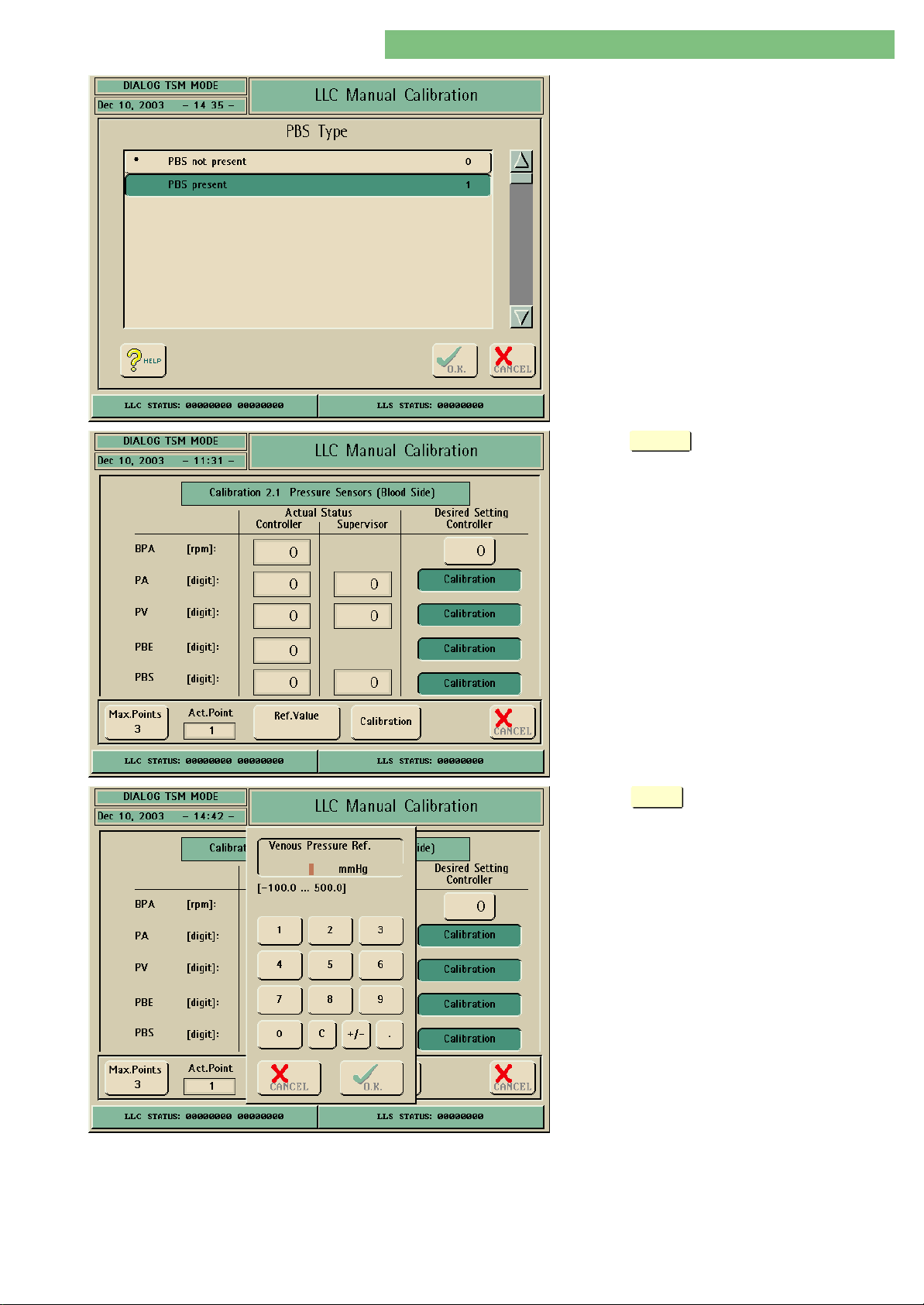
4. TSM Service Program 6/2004 4 99
Dialog/Dialog Advanced
Open the PBS Type menu with the PBS Type key. If
the pressure sensor PBSPBS is present activate with
PBS Present (Dialog with two blood pumps).
Press the
Common Calibration
key for a combined calibration
(-100 mmHg, 0 mmHg, +500 mmHg) of the
pressure sensors PAPA, PVPV , PBEPBE and PBSPBS. A
calibration window is opened if the key is selected.
Note
PAPA must be calibrated again after the common
calibration, because PAPA has a different working
range and thus different calibration points (-300
mmHg, 0 mmHg, +300 mmHg).
Press the
Ref.Value
key to enter a reference value.
An enter window is opened if the key is selected.
MT-MD-DE08C M.KAY
DialogAd_sm_Chapter 4-3_6-2004.doc/pdf <120304> ddmmyy
B. Braun Medizintechnologie GmbH
Page 100
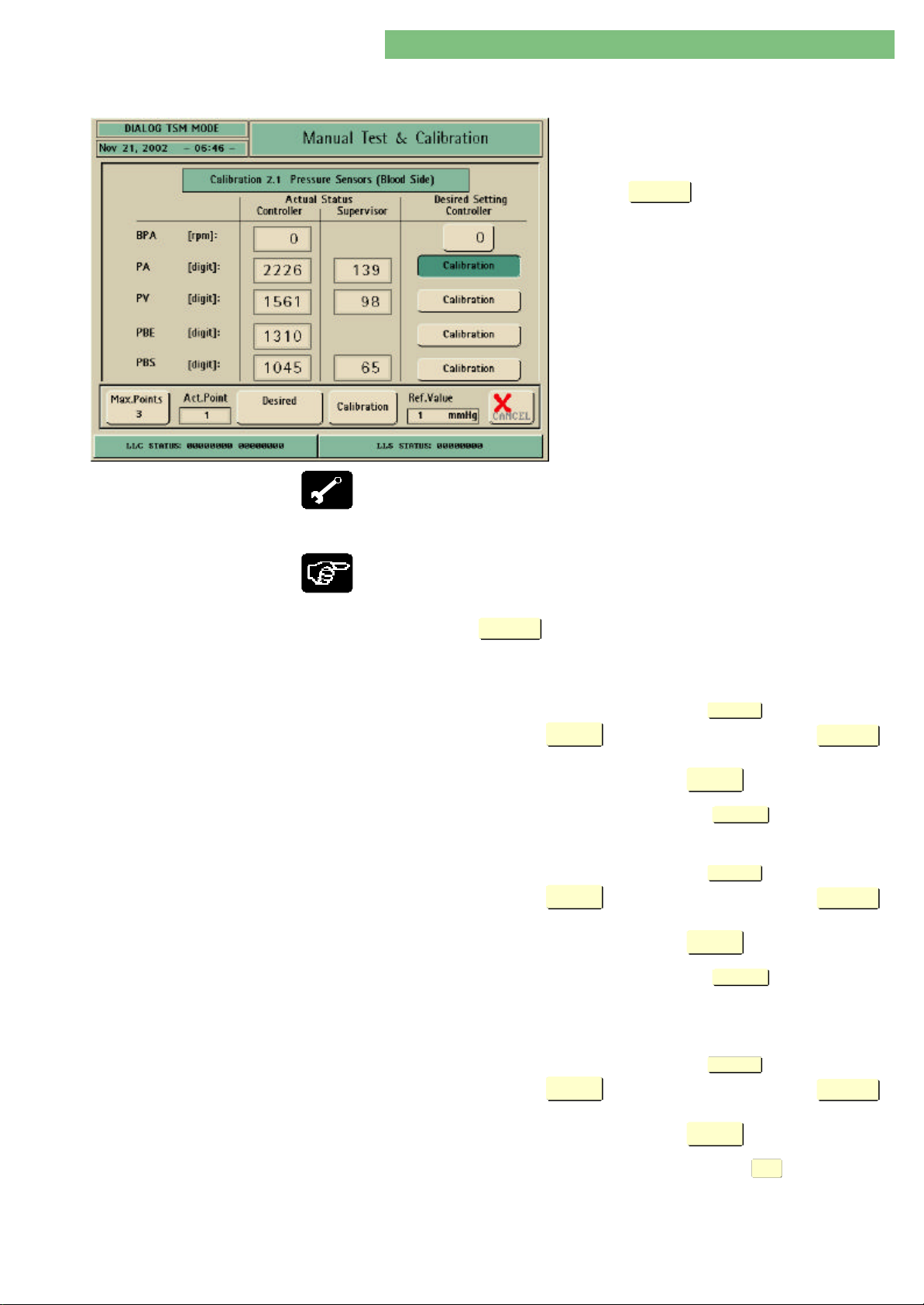
4. TSM Service Program 6/2004 4 100
Dialog/Dialog Advanced
4.10.4.1.1 Single Calibration Pressure
Sensor PA via RS-232
Dialysis measurement instrument connected to RS 232 interface (SW ≥
6.20).
A dialysis measurement instrument (HDM ≥ 99
with a software version ≥ 3.52) can be connected
to the RS 232 interface for calibration.
Press the
Calibration
key for a single calibration, e.g.
pressure sensor PAPA. A calibration window is opened
if the key is selected.
• Dialysis measurement instrument (e.g. HDM 99) and DCI option (art. no. 770
7218) or a D-Sub zero modem cable
• Syringe
• Tubing/tubing clamp
1. Connect dialysis measurement instrument to the RS 232 interface and
switch on machine, connect syringe and tubing.
2. Connect tubing end to the arterial pressure sensor PAPA.
Calibration
PA Calibration Point -300 mmHg
3. Press PA
4. Build up a pressure to -300 mmHg (± 10 mmHg) with a syringe and clamp
the tube.
5. Compare the stable reference value in the
desired value in the
key.
• The reference value is taken over in the
• The next calibration point is displayed in the
PA Calibration Point 0 mmHg 6. Remove syringe 0 mmHg.
7. Compare the stable reference value in the
desired value in the
key.
• The reference value is taken over in the
• The next calibration point is displayed in the
PA Calibration Point +300 mmHg
8. Connect syringe and Build up a pressure to +300 mmHg (± 10 mmHg) and
clamp the tube.
9. Compare the stable reference value in the
desired value in the
key.
• The reference value is taken over in the
key.
Desired
Value
window and acknowledge with the
Desired
Value
Desired
Value
window and acknowledge with the
Desired
Value
Desired
Value
window and acknowledge with the
Desired
Value
Ref.Value
X
window.
Act.Point
X
Ref.Value
X
window.
Act.Point
X
Ref.Value
X
window.
window with the
Calibration
window.
window with the
Calibration
window.
window with the
Calibration
MT-MD-DE08C M.KAY
DialogAd_sm_Chapter 4-3_6-2004.doc/pdf <120304> ddmmyy
ü
10. Acknowledge and store completed calibration with the
O.K.
key.
11. Remove dialysis measurement instrument, syringe and tubing.
B. Braun Medizintechnologie GmbH
 Loading...