

Page 1

Aesculap Power Systems
microspeed® uni
Instructions for use
microspeed® uni motor system
Gebrauchsanweisung
microspeed® uni-Motorensystem
Mode d’emploi
¾ voir www.aesculap-extra.net
Instrucciones de manejo
¾ ver www.aesculap-extra.net
Istruzioni per l’uso
¾ vedere www.aesculap-extra.net
Instruções de utilização
¾ ver www.aesculap-extra.net
Gebruiksaanwijzing
¾ zie www.aesculap-extra.net
Bruksanvisning
¾ se www.aesculap-extra.net
Käyttöohjeet
¾ ks. www.aesculap-extra.net
Инструкция по примению
¾ смотри www.aesculap-extra.net
Page 2
1 2
3
4
8
7
6
5 5
9 10 11 13
12
3
39
17 16 14
15
Page 3

18
18
22
20 19
21
25
29
26 30 28
27
23
24
31
28
33
34
35
32
36
3837
Page 4

Aesculap Power Systems
microspeed® uni motor system
Legend
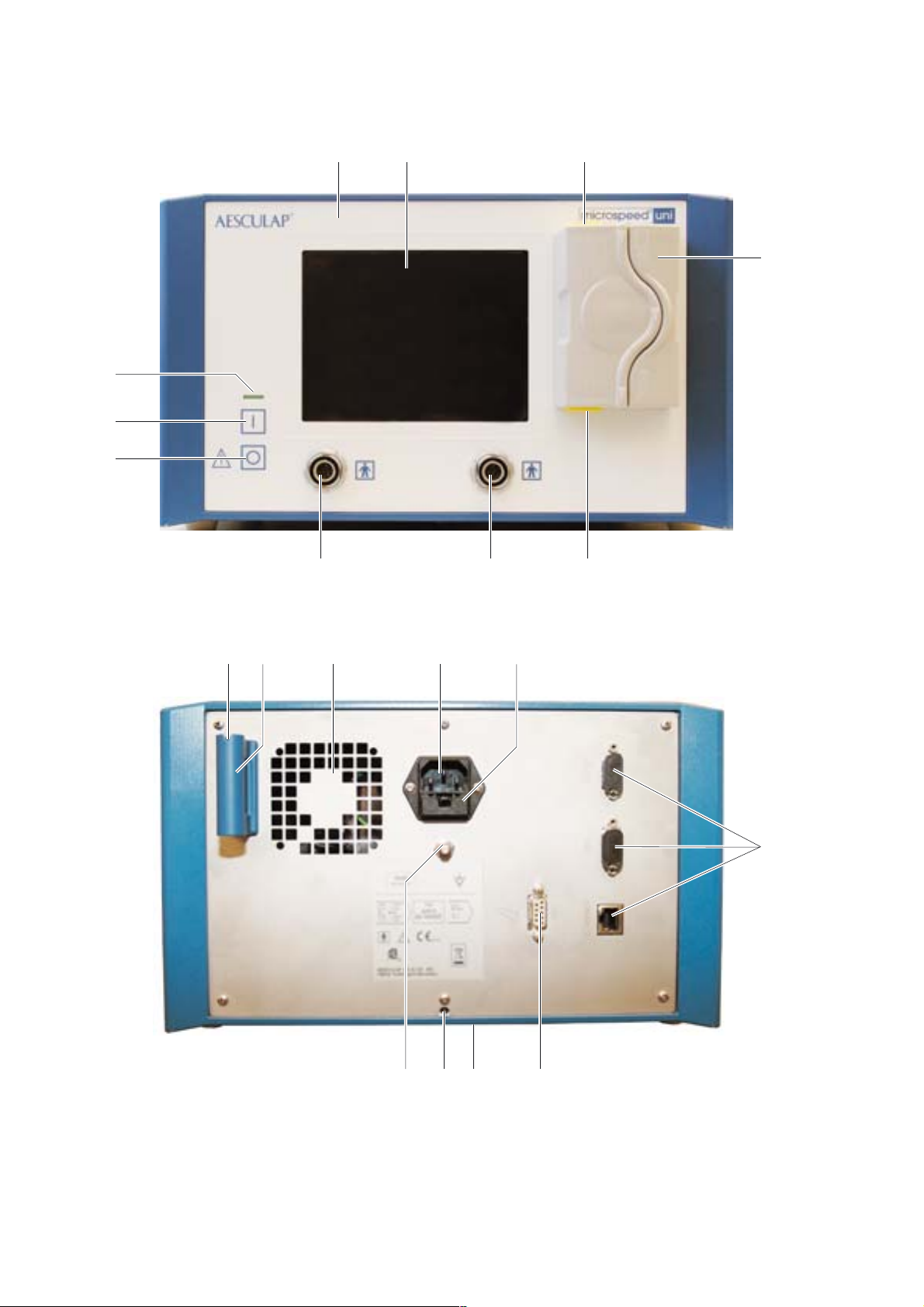
Captions first foldout page: Control unit
1 microspeed® uni control unit with cooling unit GD670
2 Display and touch control field
3 Release buttons
4 Coolant pump
5 Motor connection sockets
6 Power OFF switch
7 Power ON switch
8 Power ON indicator
9 Bottle holder
10 Bottle holder mount
11 Ventilation grate
12 Power socket
13 Fuse holder
14 Connection socket for foot control
15 Stacking cones
16 Locking screw
17 Equipotentialization connector
39 Interfaces to be used by the manufacturer only
Captions second foldout page: Foot controls, motor cables, motors
18 Foot control function button
19 Right pedal
20 Left pedal
21 microspeed® uni foot control, two pedals, GD671
22 Motor direction switch
23 Pedal
24 microspeed® uni foot control, one pedal, GD668
25 Motor release switch
26 Hand control function button
27 microspeed® uni motor cable with hand control GD673
28 Release key
29 Lever
30 Motor release switch
31 microspeed® uni motor cable for foot control GD672
32 Motors with motor-side plug connection
33 microspeed® uni mini pistol handpiece GD684
34 Upper trigger
35 Lower trigger
36 Suction control lever
37 microspeed® uni shaver handpiece GD682
38 Tube olive
Contents
1. Safe handling . . . . . . . . . . . . . . . . . . . . . . . . . . . . . . . . . . . . . . . . . 3
2. Product description . . . . . . . . . . . . . . . . . . . . . . . . . . . . . . . . . . . . 4
2.1 System components . . . . . . . . . . . . . . . . . . . . . . . . . . . . . . . . . . . . 4
2.2 Components necessary for using the product . . . . . . . . . . . . . . . 4
2.3 Intended use . . . . . . . . . . . . . . . . . . . . . . . . . . . . . . . . . . . . . . . . . . 4
2.4 Mode of operation . . . . . . . . . . . . . . . . . . . . . . . . . . . . . . . . . . . . . 4
2.4.1 Control unit. . . . . . . . . . . . . . . . . . . . . . . . . . . . . . . . . . . . . . . . . . . 4
2.4.2 Control and display interface . . . . . . . . . . . . . . . . . . . . . . . . . . . . 4
2.4.3 Control fields on the display . . . . . . . . . . . . . . . . . . . . . . . . . . . . . 5
2.4.4 Motor control fields . . . . . . . . . . . . . . . . . . . . . . . . . . . . . . . . . . . . 5
2.4.5 Pump control field . . . . . . . . . . . . . . . . . . . . . . . . . . . . . . . . . . . . . 6
2.4.6 Instruction menu . . . . . . . . . . . . . . . . . . . . . . . . . . . . . . . . . . . . . . 6
2.4.7 Motor recognition. . . . . . . . . . . . . . . . . . . . . . . . . . . . . . . . . . . . . . 6
2.4.8 Automatic saving of device settings . . . . . . . . . . . . . . . . . . . . . . . 6
2.4.9 Overload cut-out . . . . . . . . . . . . . . . . . . . . . . . . . . . . . . . . . . . . . . 7
2.4.10 Coolant pump . . . . . . . . . . . . . . . . . . . . . . . . . . . . . . . . . . . . . . . . . 7
2.4.11 Motor cable. . . . . . . . . . . . . . . . . . . . . . . . . . . . . . . . . . . . . . . . . . . 7
2.4.12 Motors . . . . . . . . . . . . . . . . . . . . . . . . . . . . . . . . . . . . . . . . . . . . . . . 9
2.4.13 Foot control devices . . . . . . . . . . . . . . . . . . . . . . . . . . . . . . . . . . . 11
2.5 Symbols . . . . . . . . . . . . . . . . . . . . . . . . . . . . . . . . . . . . . . . . . . . . . 12
2.5.1 Symbols on the control unit . . . . . . . . . . . . . . . . . . . . . . . . . . . . 12
2.5.2 Symbols on foot control, motor cable and motor . . . . . . . . . . . 12
2.5.3 Symbols in display . . . . . . . . . . . . . . . . . . . . . . . . . . . . . . . . . . . . 13
3. Preparation and setup . . . . . . . . . . . . . . . . . . . . . . . . . . . . . . . . . 15
3.1 Preparation . . . . . . . . . . . . . . . . . . . . . . . . . . . . . . . . . . . . . . . . . . 15
3.1.1 Mounting the control unit on the mobile stand . . . . . . . . . . . . 15
3.1.2 Dismounting the control unit from the mobile stand . . . . . . . . 15
3.1.3 Mains power connection . . . . . . . . . . . . . . . . . . . . . . . . . . . . . . . 15
4. Working with the microspeed® uni motor system . . . . . . . . . . . 16
4.1 System set-up . . . . . . . . . . . . . . . . . . . . . . . . . . . . . . . . . . . . . . . . 16
4.1.1 Connecting the accessories . . . . . . . . . . . . . . . . . . . . . . . . . . . . . 16
4.1.2 Connecting the foot control to the control unit . . . . . . . . . . . . 16
4.1.3 Connecting the tubing set . . . . . . . . . . . . . . . . . . . . . . . . . . . . . . 17
4.1.4 Connecting the motor cable to the control unit . . . . . . . . . . . . 17
4.1.5 Connecting a motor (GD674, GD676, GD677, GD678
and GD679) to the motor cable. . . . . . . . . . . . . . . . . . . . . . . . . . 18
4.1.6 Switching on the control unit/Automatic self-test . . . . . . . . . . 18
4.1.7 Connecting handpieces/attachments/blades . . . . . . . . . . . . . . . 18
4.2 Function checks . . . . . . . . . . . . . . . . . . . . . . . . . . . . . . . . . . . . . . 22
4.3 Safe operation. . . . . . . . . . . . . . . . . . . . . . . . . . . . . . . . . . . . . . . . 23
4.3.1 Setting up and operating the motors GD674, GD676,
GD677, GD678 and GD679 . . . . . . . . . . . . . . . . . . . . . . . . . . . . . 23
4.3.2 Setting up and operating
the microspeed® uni shaver handpiece GD682 . . . . . . . . . . . . . 26
4.3.3 Setting up and operating
the microspeed® uni mini pistol handpiece GD684. . . . . . . . . . 28
4.4 Settings in the Instruction menu . . . . . . . . . . . . . . . . . . . . . . . . 32
4.4.1 Submenu information on the error conditions
shown on the display . . . . . . . . . . . . . . . . . . . . . . . . . . . . . . . . . . 33
4.4.2 Submenu Device-specific settings . . . . . . . . . . . . . . . . . . . . . . . 33
4.4.3 Submenu Motor (type)-specific settings . . . . . . . . . . . . . . . . . . 35
2
Page 5
5. Processing . . . . . . . . . . . . . . . . . . . . . . . . . . . . . . . . . . . . . . . . . . . 38
5.1 Processing the microspeed® uni control unit with
cooling unit GD670 and
microspeed® uni foot control devices GD668/GD671 . . . . . . . . 38
5.1.1 Cleaning/Disinfection . . . . . . . . . . . . . . . . . . . . . . . . . . . . . . . . . . 38
5.1.2 Manual cleaning/disinfecting. . . . . . . . . . . . . . . . . . . . . . . . . . . . 39
5.1.3 Control, care and inspection . . . . . . . . . . . . . . . . . . . . . . . . . . . . 39
5.1.4 Storage. . . . . . . . . . . . . . . . . . . . . . . . . . . . . . . . . . . . . . . . . . . . . . 39
5.2 Processing the microspeed® uni motors GD674, GD676,
GD677, GD678, GD679 and motor cables GD672 and GD673 . 39
5.2.1 Preparations. . . . . . . . . . . . . . . . . . . . . . . . . . . . . . . . . . . . . . . . . . 39
5.2.2 Cleaning/Disinfection . . . . . . . . . . . . . . . . . . . . . . . . . . . . . . . . . . 39
5.2.3 Mechanical cleaning/disinfecting . . . . . . . . . . . . . . . . . . . . . . . . 40
5.2.4 Manual cleaning/disinfecting. . . . . . . . . . . . . . . . . . . . . . . . . . . . 40
5.2.5 Control, care and inspection . . . . . . . . . . . . . . . . . . . . . . . . . . . . 40
5.2.6 Packaging. . . . . . . . . . . . . . . . . . . . . . . . . . . . . . . . . . . . . . . . . . . . 40
5.2.7 Sterilization method and parameters . . . . . . . . . . . . . . . . . . . . . 41
5.2.8 Sterilization for the US market . . . . . . . . . . . . . . . . . . . . . . . . . . 41
5.2.9 Storage. . . . . . . . . . . . . . . . . . . . . . . . . . . . . . . . . . . . . . . . . . . . . . 41
5.2.10 Maintenance . . . . . . . . . . . . . . . . . . . . . . . . . . . . . . . . . . . . . . . . . 41
5.3 Processing the microspeed® uni shaver handpiece GD682 . . . . 41
5.3.1 Preparations. . . . . . . . . . . . . . . . . . . . . . . . . . . . . . . . . . . . . . . . . . 41
5.3.2 Mechanical cleaning/disinfecting . . . . . . . . . . . . . . . . . . . . . . . . 41
5.3.3 Manual cleaning/disinfecting. . . . . . . . . . . . . . . . . . . . . . . . . . . . 42
5.3.4 Control, care and inspection . . . . . . . . . . . . . . . . . . . . . . . . . . . . 42
5.3.5 Packaging. . . . . . . . . . . . . . . . . . . . . . . . . . . . . . . . . . . . . . . . . . . . 42
5.3.6 Sterilization method and parameters . . . . . . . . . . . . . . . . . . . . . 42
5.3.7 Sterilization for the US market . . . . . . . . . . . . . . . . . . . . . . . . . . 42
5.3.8 Storage. . . . . . . . . . . . . . . . . . . . . . . . . . . . . . . . . . . . . . . . . . . . . . 42
5.3.9 Maintenance . . . . . . . . . . . . . . . . . . . . . . . . . . . . . . . . . . . . . . . . . 43
5.4 Processing
the microspeed® uni mini pistol handpiece GD684 . . . . . . . . . . 43
5.4.1 Preparations. . . . . . . . . . . . . . . . . . . . . . . . . . . . . . . . . . . . . . . . . . 43
5.4.2 Cleaning/Disinfection . . . . . . . . . . . . . . . . . . . . . . . . . . . . . . . . . . 43
5.4.3 Mechanical cleaning/disinfecting . . . . . . . . . . . . . . . . . . . . . . . . 43
5.4.4 Manual cleaning/disinfecting. . . . . . . . . . . . . . . . . . . . . . . . . . . . 44
5.4.5 Control, care and inspection . . . . . . . . . . . . . . . . . . . . . . . . . . . . 44
5.4.6 Packaging. . . . . . . . . . . . . . . . . . . . . . . . . . . . . . . . . . . . . . . . . . . . 44
5.4.7 Sterilization method and parameters . . . . . . . . . . . . . . . . . . . . . 44
5.4.8 Sterilization for the US market . . . . . . . . . . . . . . . . . . . . . . . . . . 44
5.4.9 Storage. . . . . . . . . . . . . . . . . . . . . . . . . . . . . . . . . . . . . . . . . . . . . . 44
5.4.10 Maintenance . . . . . . . . . . . . . . . . . . . . . . . . . . . . . . . . . . . . . . . . . 45
6. Maintenance . . . . . . . . . . . . . . . . . . . . . . . . . . . . . . . . . . . . . . . . . 45
7. Troubleshooting list. . . . . . . . . . . . . . . . . . . . . . . . . . . . . . . . . . . . 46
7.1 Malfunctions with error numbers . . . . . . . . . . . . . . . . . . . . . . . . 46
7.2 Other malfunctions . . . . . . . . . . . . . . . . . . . . . . . . . . . . . . . . . . . . 48
7.3 Fuse change . . . . . . . . . . . . . . . . . . . . . . . . . . . . . . . . . . . . . . . . . . 49
8. Technical Service . . . . . . . . . . . . . . . . . . . . . . . . . . . . . . . . . . . . . . 49
9. Accessories/Spare parts . . . . . . . . . . . . . . . . . . . . . . . . . . . . . . . . 49
9.1 Accessories. . . . . . . . . . . . . . . . . . . . . . . . . . . . . . . . . . . . . . . . . . . 49
9.1.1 microspeed® uni motors, motor cables and
foot control devices . . . . . . . . . . . . . . . . . . . . . . . . . . . . . . . . . . . 49
9.1.2 Cooling unit. . . . . . . . . . . . . . . . . . . . . . . . . . . . . . . . . . . . . . . . . . 49
9.1.3 Other components. . . . . . . . . . . . . . . . . . . . . . . . . . . . . . . . . . . . . 49
9.1.4 Power cord. . . . . . . . . . . . . . . . . . . . . . . . . . . . . . . . . . . . . . . . . . . 50
9.1.5 Maintenance, processing and service . . . . . . . . . . . . . . . . . . . . . 50
9.2 Spare parts . . . . . . . . . . . . . . . . . . . . . . . . . . . . . . . . . . . . . . . . . . 50
10. Technical specifications . . . . . . . . . . . . . . . . . . . . . . . . . . . . . . . . 50
10.1 Classification acc. to directive 93/42/EEC . . . . . . . . . . . . . . . . . 50
10.2 microspeed® uni control unit with cooling unit GD670 . . . . . . 51
10.2.1 Factory settings . . . . . . . . . . . . . . . . . . . . . . . . . . . . . . . . . . . . . . 51
10.3 Low-speed motors . . . . . . . . . . . . . . . . . . . . . . . . . . . . . . . . . . . . 51
10.3.1 Low-speed motors with micro-Line coupling. . . . . . . . . . . . . . . 51
10.3.2 Low-speed motor with mini-Line coupling . . . . . . . . . . . . . . . . 52
10.4 High-speed motors . . . . . . . . . . . . . . . . . . . . . . . . . . . . . . . . . . . . 52
10.4.1 High-speed motors with Hi-Line coupling . . . . . . . . . . . . . . . . . 52
10.5 microspeed® uni shaver handpiece GD682. . . . . . . . . . . . . . . . . 52
10.6 microspeed® uni mini pistol handpiece GD684 . . . . . . . . . . . . . 53
11. Disposal . . . . . . . . . . . . . . . . . . . . . . . . . . . . . . . . . . . . . . . . . . . . . 53
12. Distributor in the US/Contact in Canada
for product information and complaints . . . . . . . . . . . . . . . . . . 53
1. Safe handling
CAUTION
Federal law restricts this device to sale by or on order of a physician!
Risk of death by electric shock!
¾ The user must not open the control unit under any
DANGER
Note
For handling and operating the products that are used with the
microspeed® uni motor system, always observe the instructions for use of
the respective products. The present instructions for use only describe the
handling and operation of the “microspeed® uni motor system”.
¾ Prior to use, check for proper condition and functioning of the product.
¾ Observe “Notes on Electromagnetic Compatibility (EMC)”, see
TA022130.
¾ To avoid damaging the product through improper setup or operation
and mitigating the warranty and liability on the part of the product’s
manufacturer:
– Use the product only according to these instructions for use.
– Follow the safety instructions and maintenance advisories.
– Only combine Aesculap products with each other.
¾ Ensure that the products and accessories are operated and used only
by persons with the requisite training, knowledge or experience.
¾ Keep the instructions accessible for the O.R. personnel.
¾ Always adhere to applicable standards.
¾ Verify that the electrical installations in the room in which the
equipment is to be used conform to IEC standards.
¾ Unplug the device by pulling on the plug, and never on the power cord.
¾ Do not use the control unit and motors in explosion hazard areas.
¾ Prior to use, carry out sterile processing of motor(s), motor cable,
tubing, handpiece(s) and tools.
¾ Operate the handpieces only at the recommended motor speeds.
circumstances.
¾ Connect product only to mains with protective circuit.
3
Page 6

Aesculap Power Systems
microspeed® uni motor system
2. Product description
2.1 System components
Designation Art. no.
microspeed® uni control unit with cooling unit GD670
Bottle holder GD412804
Instructions for use TA022089
Notes on Electromagnetic Compatibility (EMC) TA022130
2.2 Components necessary for using the product
• microspeed® uni control unit with cooling unit GD670
• Power cord
• Motor
• Motor cable
(when using a motor with a motor-side plug connection)
• Foot control
(when using a motor cable without hand control, or the shaver
handpiece)
• Bottle holder
(when using the coolant pump)
•Tubing set
(when using the coolant pump)
• Surgical suction device
(when using the shaver handpiece)
2.3 Intended use
The microspeed® uni motor system is a universal system with respect to
its range of applications and to the system composition and its variety of
uses.
The microspeed® uni motor system is used in orthopedics/traumatology,
neurosurgery, spine surgery, hand/foot surgery, ENT/OMF surgery, plastic
surgery and arthroscopy.
The microspeed® uni motor system can be operated as complete from the
sterile area, either through foot control or through hand control.
2.4 Mode of operation
The microspeed® uni motor system comprises the following components:
• Control unit with coolant pump, for universal application
• Two motor cables (with or without hand control)
• Various motors with different coupling types
• Pistol handpiece
• Shaver handpiece
• Two foot control devices
2.4.1 Control unit
Control unit 1 has been designed for a mains voltage rating of 100 V to
240 V/50 Hz to 60 Hz. The mains voltage is transformed so that the motors
run at safety low voltage.
Control unit 1 is equipped with two motor connection sockets 5 for
connecting two (different) motors, and with one foot control connection
socket 14 (on rear panel).
The following devices can be connected to control unit 1 at the same time:
•Two motors and
• One foot control (GD668 or GD671).
Note
Do not connect two shaver handpieces GD682 at the same time.
Only one motor can be activated at any one time.
Motors with motor-side plug connection (GD674, GD676, GD677, GD678
and GD679) can be operated either through hand control (motor cable
GD673) or foot control GD668 or GD671 (with motor cable GD672).
Note
When two motors without hand control are connected to the control unit
(motor cable GD672), a motor can only be activated if the motor release
switch of the motor that is to be activated is in the “ON” position while the
other motor is locked (motor release switch in “OFF” position).
2.4.2 Control and display interface
Display 2 shows the present device status (operating and error conditions)
at all times. The display is divided into motor control field(s) and a pump
control field. The device parameter settings can be changed by pressing
the control keys.
For information on all the symbols used in the motor and pump control
fields, see chapter Symbols in display.
Control key “Instruction menu” calls up the Instruction menu.
4
Page 7
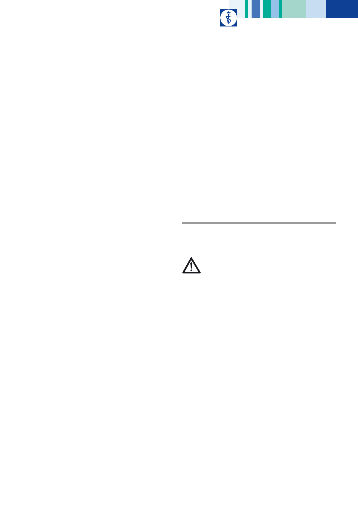
2.4.3 Control fields on the display
A B
2.4.4 Motor control fields
A
B
C
D
E
F
G
H
I
C
Fig. 1
Legend
A Motor control field(s)
B Pump control field
C Instruction menu
The display is divided into three different control fields, which are
described in the following chapters.
Fig. 2
Legend
A Status display and control key for releasing (symbol highlighted by
green background)/locking the pump
B Activation mode indicator: hand control or foot control
C Present motor speed range upper limit setting
D Qualitative display of the actual motor speed
E Control keys for increasing or reducing the motor speed range upper
limit
F Motor direction indicator
G Operating mode selected for the connected motor type, e.g. saw
program for motors GD678 and GD679
H Connected motor type
I Maximum selectable motor speed range upper limit for the connected
motor type or with the selected operating mode, respectively
Each motor connected to control unit 1 has a motor control field assigned
to it.
Two motor control fields are opened in display 2 only if two motors 32 are
actually connected to control unit 1.
Only one motor control field will be opened if only one motor is connected.
The control fields are visually identified as belonging to the respective
motor connection sockets 5.
5
Page 8
Aesculap Power Systems
A
C
microspeed® uni motor system
A motor control field is displayed as an active control field when the motor
assigned to the motor control field:
• is operated
• was the last motor operated.
The symbol of the connected motor type is highlighted by a green
background whenever a motor control field is released for operation.
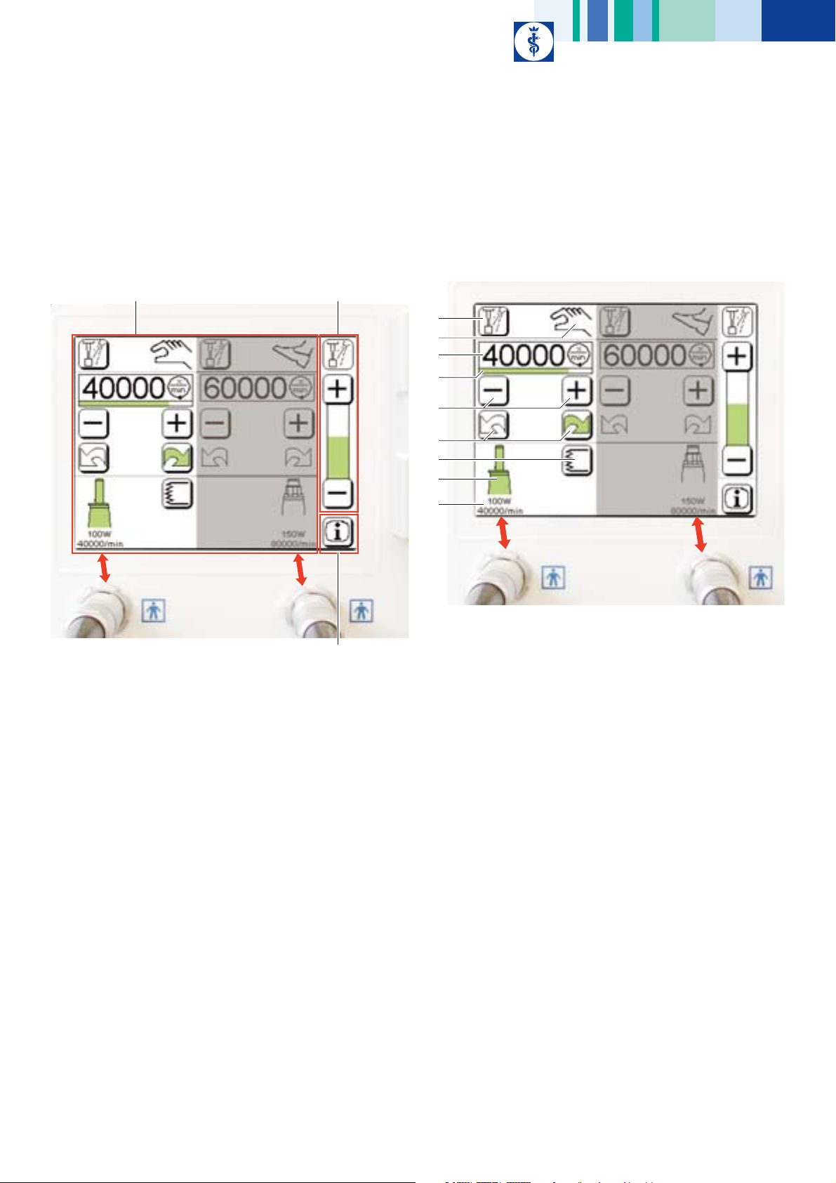
2.4.5 Pump control field
Fig. 3
Legend
A Status indicator symbol of coolant pump 4. The symbol is highlighted
by a green background while the pump is active. The pump can only
be activated if it has been released for operation and if the motor is
active.
B Control keys for increasing or reducing the delivery rate
C Display of selected dosage
The preset dose level C applies to the motor whose settings are displayed
in the (white background) motor control field.
2.4.6 Instruction menu
Note
The Instruction menu can only be called up at the control unit.
This control key is pressed to call up the Instruction menu. In the
Instruction menu, information about the error conditions output to the
display and device settings such as the user language and the volume of
the acoustic alarm/notification signal can be changed.
Motor-type specific adjustments and settings can be carried out here, too:
• Slow-down and speed-up ramps for each motor type
• Oscillating or tapping mode (for pistol handpiece GD684)
• Oscillation frequency and speed-up ramp in oscillating mode (in
Shaving mode of operation of shaver handpiece GD682)
• Reset: to restore the factory settings
B
2.4.7 Motor recognition
Control unit 1 recognizes the motor type connected to one of the motor
connection sockets 5 of control unit 1 and displays the type in the
respective motor control field of display 2. The most recent settings for this
motor type at the same motor connection socket are shown on display 2.
B
The settings can be changed within the motor-specific setting ranges,
either on the display or through hand or foot control (in the Device
settings menu), see chapter Technical specifications.
The motor control field of the most recently activated motor is always
brightly highlighted, whereas the motor control field of the motor that is
not the one that was most recently activated or locked is displayed with
a gray background. When only one motor is connected to control unit 1,
the corresponding control field is highlighted, if this motor is not locked.
Saw program (only for low-speed motors GD678 and GD679)
In this program the maximum motor speed is limited to 16,000 1/min. The
settings most recently used with the saw program (motor speed range
upper limit, dose level for coolant pump 4) are recalled automatically.
2.4.8 Automatic saving of device settings
The most recent settings for this motor type at this motor connection
socket (speed range upper limit, delivery rate, etc.), are called up
automatically as soon as the same motor type is recognized again as
connected at the same motor connection socket of control unit 1 after a
motor change.
Note
After each device start-up both the coolant pump and motor type-specific
special functions such as the saw program (for GD678 and GD679) or the
oscillating or tapping mode (for GD684) are always inactive (even if they
had been released or activated before). All parameters are reset when the
operating key "Factory setting" in the Instruction menu is pressed.
6
Page 9

2.4.9 Overload cut-out
To protect the connected motors against thermal destruction, the system
features a separate motor temperature monitoring device. For this
purpose, a temperature module is integrated in the device.
•1st Level:
As soon as the temperature module indicates a motor temperature
above 75 °C and below 90 °C, an acoustic warning is sounded and the
message “Temp. Motor” flashes on the display. Any further overload
causes control unit 1 to switch to level 2.
• 2nd Level:
As soon as a motor temperature in excess of 90 °C is detected, the
motor is switched off and the message “Error 7 – Motor overheated” is
shown on display 2.
After a cooling-down period the motor can be activated again.
Alternatively, the temperature module is reset, and work can be continued
as soon as the overheated motor has been replaced. We recommend
keeping a replacement motor on standby.
2.4.10 Coolant pump
Note
The coolant pump only works when a motor is running!
At power-on of the control unit, coolant pump 4 is always deactivated
(even if it had been released for operation at an earlier time).
The microspeed® uni control unit 1 is fitted with a coolant pump 4. This
coolant pump serves exclusively for cooling or irrigating the tools. The
delivery rate at the highest dose level is approx. 80 ml per minute. The
coolant pump can be activated either in the respective motor control field
or through the appropriate hand or foot control device. The delivery rate
can be selected via the pump control field or through the Device settings
menu, see chapter Submenu Device-specific settings.
Exception: When using pistol handpiece GD684, the pump can be
activated, and the delivery rate can be changed, only via the appropriate
control fields on the control unit.
Any one of 21 dosage settings can be selected. At dosage settings 1 to 5,
coolant pump 4 operates in intermittent mode. The pump can be switched
on and off, and the delivery rate can be changed, even while the motor is
active. Once the motor was active for more than two seconds, a special
drive control prevents further coolant from dripping out.
2.4.11 Motor cable
Risk of injury due to uncontrolled movement of skin
abrading handpiece GB280 in conjunction with a motor
WARNING
Note
A motor cable is needed to connect motors (with motor-side plug
connection) GD674, GD676, GD677, GD678 and GD679 to the control unit.
The microspeed® uni motor system comprises one motor cable for foot
control (GD672) and one motor cable with hand control (GD673). Both
motor cables can be used in connection with all motors with a motor-side
plug connection. Either of the two motor cables can be connected at any
of the two motor connection sockets 5.
Notes
The choice of motor cable depends on the application and which handpiece
is to be used.
For using saws GB128R, GB129, GB130R and motor cable with hand
control GD673, we recommend guiding the saw with both hands for
optimal handling. If single-handed saw guidance is required, use motor
cable GD672 with a foot control device.
cable with hand control GD673!
¾ Use skin abrading handpiece GB280 only with motor
cable GD672 and foot control.
7
Page 10
Aesculap Power Systems
microspeed® uni motor system
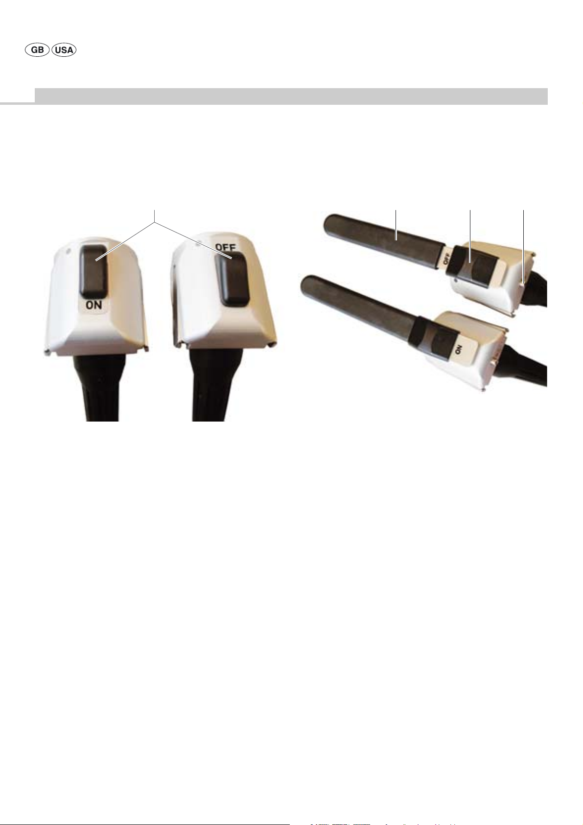
microspeed® uni motor cable for foot control GD672
30
Fig. 4
Legend
30 Motor release switch
Note
This motor cable can only be used in connection with a foot control.
The motor coupled to this motor cable can only be activated if motor
release switch 30 is in the “ON” position. When two motor cables GD672
are used at the same time, a motor can be activated only if it has been
released (motor release switch 30 in position "ON") while the other motor
is deactivated (motor release switch 30 in position "OFF").
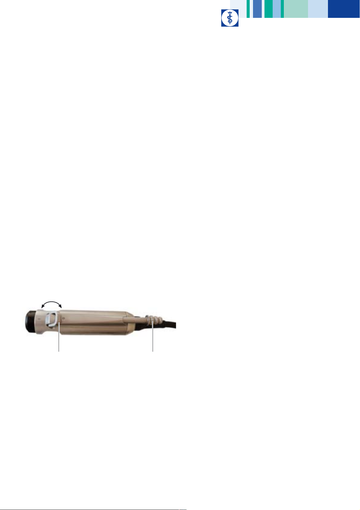
microspeed® uni motor cable with hand control GD673
2629 25
Fig. 5
Legend
25 Motor release switch:
Position "ON": Motor released for operation
Position "OFF": Motor locked against operation
26 Hand control function button:
Short actuation: Switching on/off the coolant pump
Pressing for more than three seconds (with the motor inactive):
Change to Device settings menu, siehe Kapitel Changing the settings
in the Device settings menu through hand control
29 Lever:
Actuator for motor speed setting
Note
This motor cable can not be used in connection with a foot control.
The motor coupled to this motor cable can only be activated if the motor
release switch is in its “ON” position.
8
Page 11
2.4.12 Motors
Motors with motor-side plug connection
Note
A motor cable GD672 or GD673 is required for connecting motors with
motor-side plug connection to the control unit!
Depending on the field of application, there are five different motor types
available, with the three Aesculap standard coupling systems Hi-Line,
micro-Line (Intra coupling system to DIN 13940/ISO 3964) and mini-Line.
Each motor can be operated in right or left (clockwise or
counterclockwise) rotation mode. When a motor is running in leftrotation mode, control unit 1 issues an acoustic signal.
For the performance data and parameters to be set for the individual
motor types, see chapter Technical specifications.
Motor types GD678 and GD679 offer the option to select a saw program.
In this program the maximum motor speed is limited to 16,000 1/min.
Motors with fixed motor cable GD682 and GD684
Note
The motors are directly connected to the control unit. An additional motor
cable is not required!
For the performance data and parameters to be set for the individual motor
types, see chapter Technical specifications.
microspeed® uni shaver handpiece GD682
Notes
Always observe the instructions for use of blades TA011579.
Only use Aesculap blades.
Shaver handpiece GD682 can only be used with foot control GD671 and a
surgical suction device (e.g. GF200 or GF210).
Shaver handpiece GD682 can be used if:
• a motor with motor cable GD673 is connected at the second motor
connection socket, or
• a pistol handpiece GD684 is connected at the second motor connection
socket, or
• a motor with motor cable GD672 is connected at the second motor
connection socket and the motor release switch of that cable is in its
“OFF” position, or
• only one shaver handpiece GD682 is connected to control unit 1.
There are two types of blades available for shaver handpiece GD682:
reamer and shaver blades.
Control unit 1 recognizes whether the coupled blade is a reamer or a
shaver blade. The respective mode of operation (reaming or shaving) is
indicated on the display.
An acoustic signal is issued whenever a blade of a different type is
inserted. At the same time the respective symbol is displayed in the
appropriate control field.
With a reamer blade inserted, left-rotation and right-rotation modes are
avilable, but not the oscillating mode. The maximum speed is limited to
8,000 1/min. The symbol for the "Reaming" operating mode is displayed in
the control field.
With a shaver blade inserted, right-rotation and left-rotation operating
modes are available. The maximum speed is limited to 5,000 1/min. The
symbol for the "Shaving" operating mode is displayed in the control field.
36 38
Fig. 6
Legend
36 Suction control lever:
Lever for continuous regulation of the suction power
38 Tube olive:
Connection to the surgical suction device via a suction tube
9
Page 12

Aesculap Power Systems
microspeed® uni motor system
microspeed® uni mini pistol handpiece GD684
34
35
Fig. 7
Legend
34 Upper trigger
35 Lower trigger
Note
The pistol handpiece can be locked against inadvertent actuation by gently
pressing and turning the upper trigger by 90°.
The pistol handpiece cannot be used with foot control.
Pistol handpiece GD684 is fitted with the Aesculap mini-Line coupling
system.
A protective sleeve is supplied with the handpiece. This sleeve serves to
protect against injury and damage when inserting Kirschner wires.
There are two operating modes of pistol handpiece GD684:
• Standard operation
• Oscillating or tapping mode
If control unit 1 recognizes a pistol handpiece GD684 connected, the
pistol handpiece will operate in the Standard mode (factory setting). The
device parameter settings (speed range upper limit, delivery rate, pump
status) can be changed only via the touch control field of control unit 1.
Oscillating or tapping mode can be selected via the Instruction menu. The
symbol for “Oscillating or tapping mode” is displayed in the respective
motor control field. Oscillating or tapping mode is activated though the
upper trigger. An acoustic notification signal is sounded and “Oscillating
or tapping mode active” flashes in the respective motor control field. In
this mode of operation, the speed range upper limit cannot be changed via
the touch control field on control unit 1.
The oscillating or tapping mode can be deactivated again by pressing the
upper trigger. After each power-up of the control unit and connection of
the pistol handpiece, oscillating or tapping mode is always deactivated
and needs to be activated anew via the pistol handpice. The preselected
setting in the Instruction menu is saved and remains in memory even
through subsequent system restarts.
Standard operation:
Right and left rotation mode (when in left-rotation mode, control unit 1
issues an acoustic signal).
Motor direction switch/trigger for left rotation 34, see Fig. 7:
• Pressing lower trigger 35 while holding down upper trigger 34 makes
the pistol handpiece operate in left-rotation mode.
• The motor direction is changed by pressing trigger 34 with trigger 35
already actuated.
Motor speed control trigger 35:
• Actuator for motor speed setting (motor speed proportional to
actuator travel).
• If only trigger 35 is pressed, the pistol operates in right rotation mode.
Oscillating or tapping mode:
Activating or deactivating the operating mode, see Fig. 7:
• This mode of operation is activated (and deactivated) by pressing and
holding upper trigger 34 for three seconds.
Working in “Oscillating or tapping mode”:
• The pistol handpiece is operated in tapping mode by pressing lower
trigger 35 within the first half of the total trigger travel. The motor
speed is proportional to the actual trigger travel.
Tapping mode means: Clockwise rotation by a certain angle (forward step)
followed by counterclockwise rotation (backward step) by a smaller angle.
• The pistol handpiece is operated in oscillating mode by pressing lower
trigger 35 within the second half of the total trigger travel. The motor
speed is proportional to the actual trigger travel.
Oscillating mode means: Clockwise rotation by a certain angle followed by
counterclockwise rotation by the same angle.
The pistol handpiece is operated in left-rotation mode by pressing lower
trigger 35 at the same time as upper trigger 34.
10
Page 13

2.4.13 Foot control devices
Notes
The microspeed® uni motor system includes two different foot controls
(GD668 and GD671).
Only one foot control can be connected to control unit GD670 at any time.
microspeed® uni foot control, one pedal, GD668
microspeed® uni foot control, two pedals, GD671
18
18
22
23
Fig. 8
Legend
18 Foot control function button:
Short actuation: Switching on/off the coolant pump
Actuation for more than three seconds (with the motor inactive):
Changing to Device settings menu, see chapter Changing the settings
in the Device settings menu through the foot control
22 Motor direction switch:
Selection of right or left rotation
23 Pedal:
Actuator for motor speed setting
20
Fig. 9
19
Legend
18 Foot control function button:
Short actuation: Switching on/off the coolant pump
Actuation for more than three seconds (with the motor inactive):
Change to Device settings menu, see chapter Changing the settings in
the Device settings menu through the foot control.
19 Right pedal:
Actuator for motor speed setting in right rotation
20 Left pedal:
Actuator for motor speed setting in left rotation
11
Page 14

Aesculap Power Systems
microspeed® uni motor system
2.5 Symbols
2.5.1 Symbols on the control unit
Adhere to instructions for use
Type BF application component
Input from irrigation bottle (coolant pump)
Outlet to handpiece (coolant pump)
Pumping direction (coolant pump)
Equipotentialization connector
Fuse
2.5.2 Symbols on foot control, motor cable and motor
Foot control function button
(Foot control GD668, GD671, motor cable GD673)
Motor direction switch
Selection of left or right rotation
(Foot control GD668)
Pedal for left/right rotation
(according to the motor direction set through the motor
direction switch, foot control GD668)
Pedal for right rotation
(Foot control GD671)
Pedal for left rotation
(Foot control GD671)
Oscillating operation when both pedals are pressed
(only allowed in "Shaving" mode in conjunction with
shaver handpiece GD682 , foot control GD671)
Class AP anesthetic test
(EN 60601-1)
(Foot controls GD668 and GD671)
Enclosure protection type to DIN EN 60529
IPX8
(Foot controls GD668 and GD671)
Alternating current
Foot control
Marking of electric and electronic devices according to
directive 2002/96/EC (WEEE), see chapter Disposal.
Release
(Motors GD674, GD682 and GD684)
Motor speed control
(Motor GD684)
Right/left rotation switch
(Motor GD684)
Oscillating or tapping mode:
(Motor GD684)
Protection against inadvertent activation
(Motor GD684)
12
Page 15
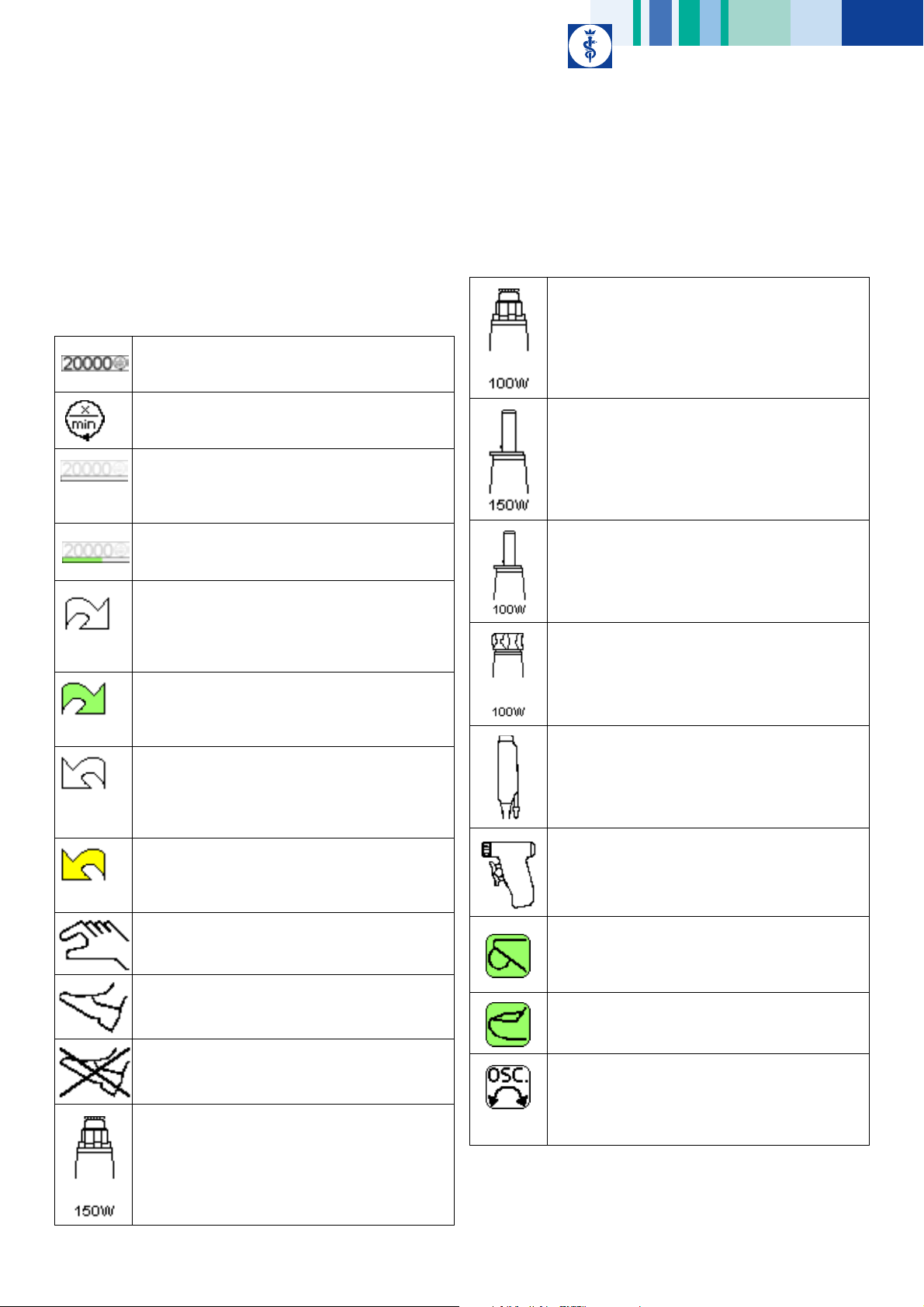
2.5.3 Symbols in display
Display symbols in the motor control fields
(Set) motor speed range upper limit
(example: 20,000 1/min)
GD677 microspeed® uni Hi 100 motor (high-speed motor;
100 W; coupling system: Hi-Line (XS) connected
If the motor can be activated (is released), the symbol is
highlighted by a green background
Motor speed in 1/min
Qualitative display of the actual motor speed (for shaver
handpiece GD682: actual tool speed)
Symbol displayed on gray background in motor control
field if the respective motor is not activated
Qualitative display of the actual motor speed (for shaver
handpiece GD682: actual tool speed);
active while motor is operated
Motor direction indicator for right rotation
when the motor is inactive or when right rotation was
not selected through foot control GD668;
in an inactive motor control field, this symbol is displayed
on a gray background
Motor direction indicator for right rotation
active when the motor is operated or in standby, provided
this motor direction was selected and foot control GD668
is connected to the control unit
Motor direction indicator for left rotation
when the motor is inactive or when left rotation was not
selected through foot control GD668;
in an inactive motor control field, this symbol is displayed
on a gray background
Motor direction indicator for left rotation
active when the motor is operated or in standby, provided
this motor direction was selected and foot control GD668
is connected to the control unit
Hand control
active if connected hand control is recognized
Foot control
active if connected foot control is recognized and at least
one motor is not operated through a hand control device
No response when foot control is pressed down
active if neither a foot control nor a hand control device
is recognized as connected
GD676 microspeed® uni Hi 150 motor (high-speed motor;
150 W; coupling system: Hi-Line (XS) connected
If the motor can be activated (is released), the symbol is
highlighted by a green background
GD678 microspeed® uni micro 150 motor (low-speed
motor; 150 W; coupling system: micro-Line)
If the motor can be activated (is released), the symbol is
highlighted by a green background
GD679 microspeed® uni micro 100 motor (low-speed
motor; 100 W; coupling system: micro-Line)
If the motor can be activated (is released), the symbol is
highlighted by a green background
GD674 microspeed® uni mini 100 motor (low-speed
motor; 100 W; coupling system: mini-Line) connected
If the motor can be activated (is released), the symbol is
highlighted by a green background
GD682 microspeed® uni shaver handpiece connected
If the motor can be activated (is released), the symbol is
highlighted by a green background
GD684 microspeed® uni mini pistol handpiece (coupling
system: mini-Line) connected
If the motor can be activated (is released), the symbol is
highlighted by a green background
Operating mode "Reaming"
(only in connection with shaver handpiece GD682, if no
shaver tip is recognized)
Operating mode "Shaving"
(only in connection with shaver handpiece GD682, if a
shaver tip is recognized)
Oscillating or tapping mode (only in connection with
pistol handpiece GD684)
Displayed when oscillating or tapping mode was released
in the instruction menu, but not activated through the
pistol handpiece
13
Page 16

Aesculap Power Systems
microspeed® uni motor system
Oscillating or tapping mode active:
(only in connection with pistol handpiece GD684)
Displayed when oscillating or tapping mode was released
in the Instruction menu and is activated through the
pistol handpiece (by holding down the upper trigger for
three seconds)
Display/Control key symbols in the motor control fields Display symbols in the pump control field
Increasing the motor speed range upper limit
Reducing the motor speed range upper limit
Status indicator/control key of the saw program
This symbol indicates that the saw program, which can
only be selected in connection with motors GD678 and
GD679, is inactive
Status indicator/control key of the saw program
This symbol indicates that the saw program, which can
only be selected in connection with motors GD678 and
GD679, is active
Motor direction indicator when left rotation was not
selected, and control key for selecting left rotation
The control key symbol is only displayed, and a motor
direction can only be selected if hand control GD673 is
connected
Motor direction indicator when left rotation was
selected, and control key for selecting left rotation
The control key symbol is only displayed, and a motor
direction can only be selected if hand control GD673 is
connected
Motor direction indicator when right rotation was not
selected, and control key for selecting right rotation
The control key symbol is only displayed, and a motor
direction can only be selected if hand control GD673 is
connected
Motor direction indicator when right rotation was
selected, and control key for selecting right rotation
The control key symbol is only displayed, and a motor
direction can only be selected if hand control GD673 is
connected
"Pump OFF" indicator and control key for activating the
pump
The symbol is displayed in the respective motor control
field
Control key symbols in the pump control field
Control key symbols within the display
"Pump ON" indicator and control key for activating the
pump
Active when, in connection with the selected motor, the
pump is switched on via the function button (hand or
foot control) or by actuating this field. The symbol is
displayed in the respective motor control field.
"Pump inactive" indicator
Symbol as displayed with the motor inactive, i.e. when
the pump has not been activated in the pump control
field
"Pump active" indicator
is active when the pump released in connection with the
selected and activated motor is activated
Display of selected dosage
is always active
Increasing the delivery rate
Reducing the delivery rate
Selecting the secondary control level
Instruction menu,
can only be activated when no motor is active
14
Page 17

3. Preparation and setup
Non-compliance with these rules will result in complete exclusion of any
responsibility and liability on the part of Aesculap.
¾ Observe the following regulations when setting up and operating the
product:
– the national regulations for installation and operation
– national regulations on fire and explosion protection.
– operating advisories acc. to IEC-/VDE regulations.
The following advice is given on the basis of the presently applicable
IEC-/VDE regulations:
Fire and explosion hazard!
¾ Do not use the control unit and motors in explosion
WARNING
The foot control circuit is ignition-safe and approved for operation in
medical environments acc. to IEC 601/VDE 0750.
3.1 Preparation
Note
The control unit can be mounted on an Aesculap mobile stand for
microspeed® uni (adjustable height) GA411 or on an Aesculap mobile stand
for surgical devices GD416M.
Other Aesculap devices must not be stacked on top of the control unit.
3.1.1 Mounting the control unit on the mobile stand
Note
Follow the instructions for use of the mobile stand.
hazard areas.
Legend
A Device support
15 Stacking cones
16 Locking screw
Only one device may be mounted on the mobile stand at any time, always
taking into consideration the stability of the mobile stand.
¾ Remove the caps from stacking cones 15.
¾ Remove the device feet, using a screwdriver.
¾ Move stacking cones 15 to the correct mounting positions by turning
locking screw 16 counterclockwise as far as it will go, using a
screwdriver.
¾ Position the device on the mobile stand in such a way that front edge
sits flush with device support A and stacking cones 15 sit in the
corresponding holes in device support A.
¾ Secure the device by turning locking screw 16 clockwise as far as it
will go.
¾ Gently lift the device to check if it is securely attached to device
support A.
The device is now mounted on the mobile stand.
3.1.2 Dismounting the control unit from the mobile stand
¾ Use a screwdriver to turn locking screw 16 counterclockwise as far as
it will go.
¾ Lift off the device.
¾ Reattach the device feet either by hand or with a screwdriver.
The device is now dismounted from the mobile stand.
3.1.3 Mains power connection
The voltage of the mains power must correspond to the voltage indicated
on the type plate of the device.
¾ Plug in the power cord at power cord socket 12.
¾ Plug in the mains plug at the building mains power socket.
Fig. 10
16 15 A
15
Page 18
Aesculap Power Systems
microspeed® uni motor system
4. Working with the microspeed® uni
motor system
Risk of infection and contamination!
¾ Prior to first operation, carry out sterile processing of
WARNING
WARNING
4.1 System set-up
4.1.1 Connecting the accessories
Note
Follow the instructions for use of individual accessories!
Note
micro-Line drill pistol (GB200) and arthroscopy handpiece (GB801) must
not be used with this product.
Combinations of accessories that are not mentioned in the present
instructions for use may only be employed if they are specifically designed
for the intended application and do not compromise the performance and
safety characteristics of the products.
Depending on the motor type, all handpieces and tools of this range can
be coupled through the three Aesculap standard coupling systems Hi-Line
(or Hi-Line XS), micro-Line (handpieces for drilling, reaming, sawing and
shaping, with Intra coupling system acc. to DIN 13940/ISO 3964) and
mini-Line.
For other accessories, see chapter Accessories/Spare parts and brochure
no. O22711, Aesculap Power Systems.
the motors, motor cable, tubing, handpiece and tools.
¾ Make certain that the packaging of sterile products is
undamaged.
Risk of injury caused by inadvertent activation of the
motor!
¾ Secure motors that are not actively operated against
inadvertent activation through foot or hand control.
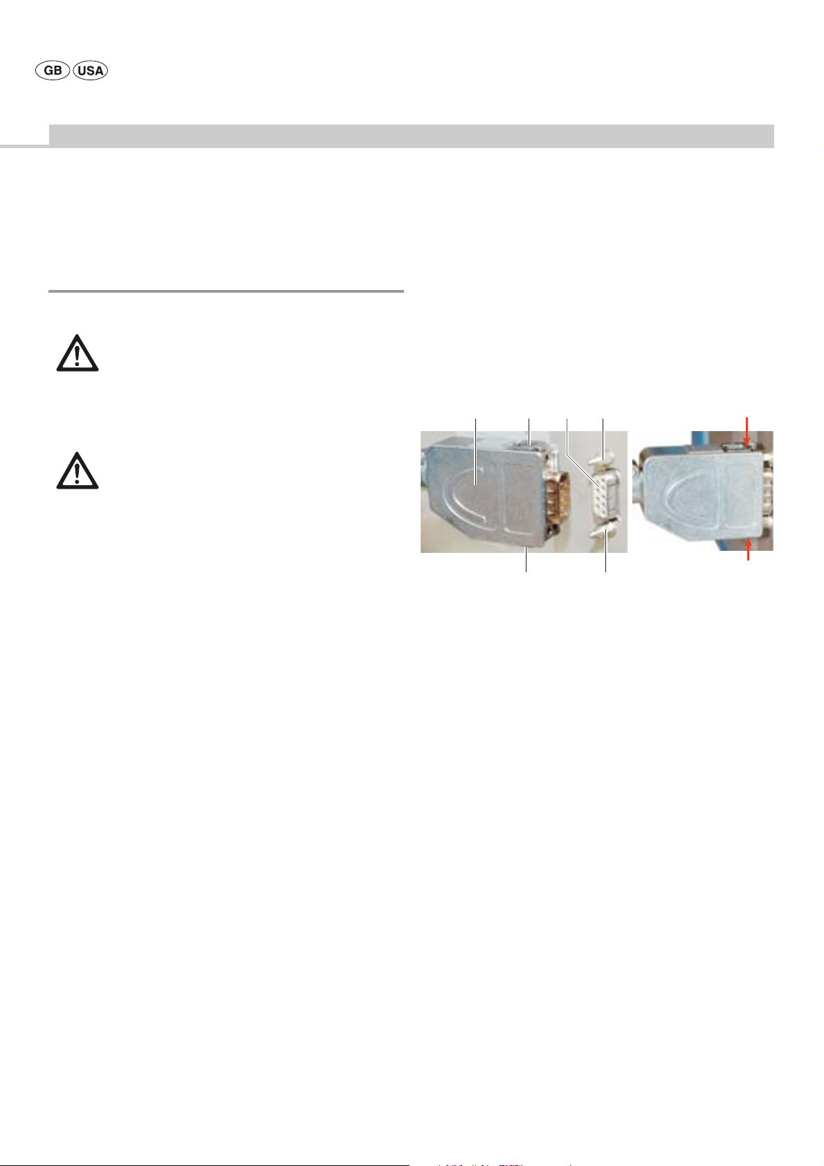
4.1.2 Connecting the foot control to the control unit
Note
Only necessary when using motor cable for foot control GD672 or shaver
handpiece GD682.
The foot control can not be used in combination with motor cable with
hand control GD673 and/or pistol handpiece GD684.
A
Fig. 11
C
C
B14
B
D
D
Legend
A Foot control connector
B Locking pins
C Locking clips
D Arrows
14 Connection socket for foot control
¾ To connect the foot control connector A to control unit 1:
Fully plug in the foot control connector A at the connection socket for
foot control 14 (in rear panel of the unit).
Locking clips C audibly engage in locking pins B, see Fig. 11.
¾ To disconnect the foot control device from control unit 1:
Simultaneously compress locking clips C (see arrows D) and unplug
connector A.
16
Page 19

4.1.3 Connecting the tubing set
Note
The tubing set is sterile! Sterile separation is carried out at the tubing.
¾ Insert bottle holder 9 for the sterile fluid bottle into bottle holder
mount 10.
¾ Insert the spike into the sterile fluid bottle.
¾ Mount the sterile fluid bottle at bottle holder 9.
3
B
4
4.1.4 Connecting the motor cable to the control unit
Note
The motor cable and the motor are sterile! Sterile separation is carried out
at the motor cable.
A
5
AA
DD
C B
Fig. 13
B
3
Fig. 12
Legend
A Arrows
B Arrows
3 Release buttons
4 Coolant pump
¾ To open coolant pump 4: Simultaneously press release buttons 3.
¾ Insert tubing: Insert the pump tube with the tube nipple into the recess
(arrows B).
¾ Close coolant pump 4: Push together the pump housing until it clicks
into position (arrows A). When doing this, ensure that the pump
enclosure is completely closed, both at the inlet (from the irrigation
bottle) and at he outlet (to the handpiece).
Legend
A Mark (motor connection socket)
B Plug
C Mark (plug)
D Arrows
5 Motor connection socket
Damage to, or destruction of, the motor cable caused by
pulling the cable!
CAUTION
¾ To connect plug B: Align plug B in such a way that mark C on the plug
¾ Fully insert plug B in the motor connection socket.
¾ To disconnect plug B: Hold plug B in the marked places (arrows D) and
¾ Always pull at the plug, never at the cable.
is aligned with mark A on motor connection socket 5.
unplug it from motor connection socket 5.
17
Page 20

Aesculap Power Systems
microspeed® uni motor system
4.1.5 Connecting a motor (GD674, GD676, GD677, GD678
and GD679) to the motor cable
32
B 28
Fig. 14
28
A
C
C
Legend
A Mark on motor cable
B Mark on motor
C Arrows
28 Release key (x2)
32 Motor
¾ To couple motor 32: Install motor 32 on the motor cable, making
certain that mark B on the motor is aligned with mark A on the motor
cable.
Motor 32 will audibly engage in its proper position.
¾ To uncouple motor 32: Compress both release keys 28 at the points
indicated by arrows C. (The motor will be pushed away slightly from
the motor cable.)
This completes the uncoupling of motor 32.
4.1.7 Connecting handpieces/attachments/blades
Risk of injury due to uncontrolled movement of skin
abrading handpiece GB280 in connection with motor cable
WARNING
WARNING
WARNING
CAUTION
Note
For using saws GB128R, GB129, GB130R and motor cable with hand
control GD673, we recommend guiding the saw with both hands for
optimal handling. If single-handed saw handling is required, use motor
cable GD672 with a foot control.
with hand control GD673!
¾ Use skin abrading handpiece GB280 only with motor
cable GD672 and foot control.
Risk of injury and material damage due to inappropriate use
of handpieces or attachments!
¾ Always follow the safety advice and information given in
the instructions for use of the handpieces and
attachments.
¾ Do not exceed the specified maximum motor speed.
Risk of injury caused by loose milling heads when operating
high-speed motors in left rotation mode!
¾ Do not use screw-coupled milling heads.
Damage to motor and handpiece!
¾ Couple/uncouple handpieces only with the motor
inactive.
4.1.6 Switching on the control unit/Automatic self-test
¾ Switch on control unit 1 at mains power ON switch 7.
Power ON indicator 8 will be illuminated.
Control unit 1 always performs a self-test when the unit is switched on.
During this test the microspeed® uni start picture is displayed.
If any malfunction is detected, an error message will be displayed, see
chapter Malfunctions with error numbers.
18
Page 21

Connecting micro-Line handpieces to low-speed motors GD678 and
GD679
Connecting Hi-Line handpieces to high-speed motors GD676 and
GD677
A 32
B
C
Fig. 15
Legend
A Handpiece
B Catch
C Centering lug
32 Motor
¾ To couple handpiece A:
Install handpiece A on centering lug C.
Handpiece A engages in its proper position.
¾ Pull at motor 32 to check that the handpiece is securely coupled.
¾ To uncouple handpiece A:
press catch B and remove handpiece A.
DB 32CA
Fig. 16
Legend
A Handpiece
B Threaded ring
C Recess
D Lugs
32 Motor
Symbol “Handpiece release”
Symbol “Handpiece locking”
Handpiece A can be coupled to motor 32 in different positions.
Coupling:
¾ To release handpiece A: Turn threaded ring B in the direction indicated
by the arrow in symbol “Handpiece release” as far as it will go.
¾ To couple handpiece A: Install handpiece A at the desired position on
motor 32, making certain that lugs D of motor 32 engage in recesses C
at handpiece A.
¾ Lock handpiece A: Turn threaded ring B in the direction indicated by
the arrow in symbol "Handpiece locking" as far as it will go (to prevent
loosening of the handpiece due to vibrations during operation).
Uncoupling:
¾ To uncouple the handpiece: Turn threaded ring B in the direction
indicated by the arrow in symbol “Handpiece release” as far as it will
go and detach handpiece A.
19
Page 22

Aesculap Power Systems
microspeed® uni motor system
Connecting Hi-Line XS handpieces to high-speed motors GD676 and
GD677
CB 32A
Fig. 17
Legend
A Handpiece
B Threaded ring
C Handpiece coupling
32 Motor
Symbol “Handpiece release”
Symbol “Handpiece locking”
Coupling:
¾ Turn threaded ring B of handpiece A in the direction indicated by the
arrow in symbol “Handpiece release” as far as it will go.
¾ Install handpiece A on handpiece coupling C of motor 32 in such a way
that the pin on the handpiece engages in one of the notches of the
handpiece coupling.
¾ Turn threaded ring B in the direction indicated by the arrow in symbol
“Handpiece locking” as far as it will go.
¾ Make certain that threaded ring B is tightened to its limit stop to
prevent it from coming loose due to vibrations during operation.
Uncoupling:
¾ Turn threaded ring B in the direction indicated by the arrow in symbol
“Handpiece release” as far as it will go.
¾ Detach handpiece A from motor 32.
Connecting mini-Line attachments to microspeed® uni mini 100
motor GD674 and microspeed® uni mini pistol handpiece GD684
A B C
Fig. 18
Legend
A mini-Line attachment
B Tension ring
C Motor drive
Coupling:
¾ Turn tension ring B on motor C in the “open” direction as indicated by
the arrow, as far as it will go.
¾ Push the coupling of mini-Line attachment A into tension ring B at
motor C as far as it will go.
¾ Turn tension ring B on motor C against the “open” direction as
indicated by the arrow, as far as it will go.
Uncoupling:
¾ Turn tension ring B on motor C in the “open” direction as indicated by
the arrow, as far as it will go.
¾ Retract mini-Line attachment out of tension ring B at motor C.
¾ If tension ring B on the coupling cannot be loosened by hand, use the
auxiliary wrench of motor C.
20
Page 23

Connecting protective sleeve GD684225 to microspeed® uni mini
pistol handpiece GD684
Coupling the blades to shaver handpiece GD682
33
Fig. 19
A
Legend
A Protective sleeve GD684225
33 Pistol handpiece
Coupling:
¾ Slide protective sleeve A onto pistol handpiece 33 so that it clicks into
position.
Uncoupling:
¾ Retract protective sleeve A from pistol handpiece 33.
Risk of injury and material damage due to inappropriate use
of the blades!
WARNING
Note
Only use Aesculap blades.
Coupling a blade to the shaver handpiece
¾ Always follow the safety advice and information given in
the respective instructions for use.
E
D
C
B
A
37
F
Fig. 20
Legend
A Blade
B Cap
C Fixation nose
D Coupling
E Unlocking sleeve
F Groove
37 Shaver handpiece
Blade A can be mounted on shaver handpiece 37 in four different
positions.
¾ Hold blade A at cap B and push it into the blade adapter of the
handpiece as far as it will go, making certain that fixation nose C sits
in groove F of the motor.
The blade window is aligned with fixation nose C.
¾ Check the firm seating of blade A by pulling blade A.
21
Page 24

Aesculap Power Systems
microspeed® uni motor system
Uncoupling a blade from the shaver handpiece
A
E
B
Fig. 21
¾ Pull back unlocking sleeve E at the handpiece in the direction of the
arrow; remove blade A, holding it at cap B.
Connecting a suction tube to shaver handpiece GD682
A3736 38
4.2 Function checks
¾ Prior to each use, inspect the entire unit for functionality and proper
condition.
¾ Verify that all components to be used function properly and are
properly connected.
The connected motor type must be indicated in the appropriate motor
control field on the display.
¾ Set the motor release switch to its "ON" position, if necessary.
The motor to be used is released.
¾ Actuate the foot or hand control down to the limit stop.
The motor starts and reaches the maximum speed indicated in the
motor control field in display 2.
The motor audibly runs smoothly and at a constant speed.
The qualitative display of the actual motor speed in the motor control
field is fully illuminated.
¾ Enable coolant pump 4 in the respective motor control field or via the
function key of the foot or hand control device.
Coolant pump 4 is started by activating the motor.
Once the motor was active for more than two seconds, a special drive
control prevents further coolant from dripping out.
Fig. 22
Legend
A Suction tube
36 Suction control lever
37 Shaver handpiece
38 Tube olive
¾ To connect suction tube A to shaver handpiece 37: Push suction
tube A (GF572 or GF573) of the surgical suction device over tube
olive 38.
22
Page 25

4.3 Safe operation
Risk of injury caused by inadvertent activation of the
motor!
WARNING
WARNING
WARNING
¾ Secure any motors that are not actively operated
against inadvertent activation through foot or hand
control.
Risk of burns to patient and user, due to hot motor/hot
handpiece/hot tool!
¾ Put down the hot motor/hot handpiece/hot tool beyond
reach of the patient.
Risk of injury and material damage due to inappropriate use
of handpieces or motors!
¾ Always follow the safety advice and information given in
the instructions for use of the handpieces and motors.
¾ Do not exceed the specified maximum motor speed.
Changing the settings in the Device settings menu on the control unit
Fig. 23
Risk of injury caused by loose milling heads when operating
high-speed motors in left rotation mode!
WARNING
¾ Do not use screw-coupled milling heads.
4.3.1 Setting up and operating the motors GD674, GD676,
GD677, GD678 and GD679
Note
The instruction menu allows changing motor type-specific settings (run-
down and run-up ramp), see chapter Instruction menu.
A motor can be operated and settings can be changed only if:
•a motor 32 is connected at control unit 1
• the motor control field is not locked, meaning
– when using the motor cable for foot control GD672, the motor
release switch is in its "ON" position
– when using the motor cable for foot control GD672, a foot control
device is connected at control unit 1
• any motor connected to the other motor connection socket is inactive.
The following settings cannot be changed while motor 32 is running:
• Motor direction (of rotation)
• Motor speed range upper limit
• Operating mode
All settings for the respective motor type and motor connection socket are
saved on exit from the settings mode.
Selecting the motor speed range upper limit
The set motor speed upper limit is indicated in the respective motor
control field in display 2 and can be adjusted via the touch control keys.
Note
The setting range and the step width for the speed range upper limit depend
on which motor was selected, see chapter Technical specifications.
¾ To increase the motor speed range upper limit: press key to increase the
motor speed range upper limit.
¾ To reduce the motor speed range upper limit: press key to reduce the
motor speed range upper limit.
Selecting the saw program (only for motors GD678 and GD679)
This key can only be activated when no motor is active.
The saw program is activated and deactivated via the control key in the
respective motor control field.
The same control key also serves as a status indicator:
• The symbol displayed on a white background means that the saw
program is not active.
• The symbol displayed on a green background means that the saw
program is active, with a maximum setting of 16,000 1/min for the
motor speed range upper limit.
The settings most recently used with the saw program (motor speed range
upper limit, dose level for coolant pump 4) are recalled automatically.
23
Page 26

Aesculap Power Systems
microspeed® uni motor system
Setting the coolant pump delivery rate
Coolant pump 4 is activated and deactivated via the control key in the
respective motor control field.
The same control key also serves as a status indicator:
• The symbol displayed on a white background means that the pump is
switched off.
• The symbol displayed on a green background means that the pump is
switched on.
¾ To increase the delivery rate: press the key to increase the delivery rate
in the pump control field.
¾ To reduce the delivery rate: press the key to reduce the delivery rate in
the pump control field.
Changing the settings in the Device settings menu through the foot
control
¾ Press and hold down foot control function button 18 for three seconds.
Control unit 1 switches to the settings mode.
Motor 32 and coolant pump 4 are disabled.
Saw program selection (only for motors GD678 and GD679)
Notes
These motors support an additional saw program. The maximum motor
speed and the coolant delivery rate are changed in the same way as for
motor types GD674, GD676 and GD677.
In the saw program, the maximum motor speed is limited to 16,000 1/min.
The settings that were used most recently with or without the saw program
are recalled and displayed automatically.
The indicator/control key for the saw program flashes in the respective
motor control field.
The saw program is activated or deactivated by pressing the respective
pedal of foot control 21/24:
• Symbol on white background: program deactivated
• Symbol on green background: program activated
¾ To switch from parameter saw program to parameter motor speed
range upper limit: briefly press foot control function button18.
Changing the motor speed range upper limit
The motor speed range upper limit display for the motor is flashing in the
motor control field.
¾ To increase the motor speed range upper limit:
– press right pedal 19 when using foot control GD671.
– for foot control GD668, set motor direction switch 22 to right
rotation and press the pedal.
If the motor speed range upper limit is reached and the pedal is still
held down, the display switches to the minimum setting for the motor
speed range upper limit before rising according to the technical
specifications of the respective motor type.
¾ To reduce the motor speed range upper limit:
– press left pedal 20 when using foot control GD671.
– for foot control GD668, set motor direction switch 22 to left
rotation and press the pedal.
If the minimum possible setting for the motor speed range upper limit
is reached and the pedal is still held down, the display switches to the
maximum setting for the motor speed range upper limit before being
reduced according to the technical specifications of the respective
motor type.
¾ To switch from parameter motor speed range upper limit to parameter
coolant pump 4: briefly press foot control function button 18.
Setting the coolant pump delivery rate
The display for the selected dosage is flashing in the pump control field.
¾ To increase the delivery rate:
– press right pedal 19 when using foot control GD671.
– for foot control GD668, set motor direction switch 22 to right
rotation and press the pedal.
If the maximum dosage is reached while the pedal is still held down,
the display switches to the minimum dosage setting and then increases
according to the preselected dosage.
¾ To reduce the delivery rate:
– press left pedal 20 when using foot control GD671.
– for foot control GD668, set motor direction switch 22 to left
rotation and press the pedal.
If the minimum dosage is reached and the pedal still held down, the
display switches to the maximum dosage setting before falling back to
the preselected dosage.
Exiting the settings mode
¾ Press and hold down foot control function button 18 for three seconds.
The settings mode is quitted automatically if no button or pedal is
pressed within five seconds.
Changing the settings in the Device settings menu through hand
control
¾ Press and hold down hand control function button 26 for three
seconds.
Control unit 1 switches to the settings mode.
Motor 32 and coolant pump 4 are disabled.
24
Page 27

Selecting the saw program (only for motors GD678 and GD679)
Notes
These motors support an additional saw program. The maximum motor
speed and the coolant delivery rate are changed in the same way as for
motor types GD674, GD676 and GD677.
In the saw program, the maximum motor speed is limited to 16,000 1/min.
The settings that were used most recently with or without the saw program
are recalled and displayed automatically.
The indicator/control key for the saw program flashes in the respective
motor control field.
The saw program is activated and deactivated through lever 29:
• Symbol on white background: program deactivated
• Symbol on green background: program activated
¾ To switch from parameter saw program to parameter motor speed
range upper limit: briefly press hand control function button 26.
Activating a motor through foot control
To activate right rotation:
– press right pedal 19 when using foot control GD671.
– when using foot control GD668, set motor direction switch 22 to
right rotation and press pedal 23.
The motor direction indicator for right rotation is illuminated in the motor
control field and motor 32 runs clockwise.
To activate left rotation:
– press left pedal 20 when using foot control GD671.
– For foot control GD668, set motor direction switch 22 to left
rotation and press pedal 23.
The motor direction indicator for left rotation is illuminated in the motor
control field and motor 32 runs counterclockwise.
Control unit 1 issues an acoustic signal.
¾ To switch on/off coolant pump 4:
briefly press foot control function button 18.
Changing the motor speed range upper limit
The motor speed range upper limit display for the motor is flashing in the
motor control field.
¾ To increase/reduce the motor speed range upper limit: actuate lever 29.
If the motor sped upper limit is reached while lever 29 is still being
actuated, the display switches to the minimum setting for the motor
speed upper limit before rising according to the technical
specifications of the respective motor type.
¾ To switch from parameter motor speed range upper limit to parameter
coolant pump: briefly press hand control function button 26.
Setting the coolant pump delivery rate
The display for the selected dosage is flashing in the pump control field.
¾ To increase or decrease the delivery rate: Actuate the lever until the
required delivery rate is displayed.
As soon as the maximum delivery rate is reached, the lowest rate will
be displayed again.
¾ To switch from parameter coolant pump to parameter motor direction:
briefly press hand control function button 26.
Setting the motor direction
The most recently set motor direction flashes in the motor control field.
¾ Actuate lever 29 until the indicator for the required motor direction
lights up.
Activating a motor with a handpiece
The selected motor direction is displayed in the motor control field.
¾ Actuate lever 29.
Motor 32 runs in the direction indicated in the motor control field.
¾ To switch on/off coolant pump 4: briefly press hand control function
button 26.
Exiting the settings mode
¾ Press and hold down hand control function button 26 for three
seconds.
The settings mode is automatically exited if no key or control element
is actuated within five seconds.
25
Page 28
Aesculap Power Systems
microspeed® uni motor system
4.3.2 Setting up and operating the microspeed® uni shaver
handpiece GD682
Risk of injury caused by inadvertent activation of the
motor!
WARNING
WARNING
Note
Shaver handpiece GD682 can only be used with foot control GD671 and a
surgical suction device (e.g. GF200 or GF210).
The instruction menu allows changing motor type-specific settings (slow-
down and speed-up ramps and oscillation frequency, speed-up ramp for
Shaving mode), see chapter Instruction menu.
Parameter settings can only be changed if:
• a motor with motor cable GD673 is connected at the second motor
• a pistol handpiece GD684 is connected at the second motor connection
• a motor with motor cable GD672 is connected at the second motor
• only one shaver handpiece GD682 is connected at the control unit and
• a foot control device is connected to the control unit.
The following settings cannot be changed while shaver handpiece GD682
is running:
• Motor direction (of rotation)
• Motor speed range upper limit
• Operating mode
All settings will be saved on exit from the settings mode.
Operating modes
There are two types of blades for shaver handpiece GD682:
• Reamer blades
• Shaver blades
Control unit 1 recognizes whether the coupled blade is a reamer or a
shaver blade. The respective mode of operation (reaming or shaving) is
indicated on the display.
An acoustic signal is issued whenever a blade of a different type is
inserted, and the respective symbol is displayed in the appropriate motor
control field.
¾ Secure any motors that are not actively operated
against inadvertent activation through foot or hand
control.
Risk of injury and material damage due to inappropriate use
of the blades!
¾ Always follow the safety advice and information given in
instructions for use TA011579.
¾ Do not exceed the specified maximum motor speed.
connection socket without being active, or
socket without being active, or
connection socket and the motor release switch is in its “OFF” position,
or
With a reamer blade coupled, the motor can be operated in right or left
rotation, but not in oscillating mode. The maximum speed is limited to
8,000 1/min. The symbol for the "Reaming" operating mode is displayed in
the control field.
With a shaver blade coupled, the motor can be operated in right or left
rotation as well as in oscillating mode. The maximum speed is limited to
5,000 1/min. The symbol for the "Shaving" operating mode is displayed in
the control field.
Changing the settings in the Device settings menu on the control unit
Notes
For shaver handpiece GD682, the tool speed is indicated in the display.
The setting range and the step width for the speed range upper limit depend
on which operating mode (cutting or shaving) is selected, see chapter
Technical specifications.
Selecting the motor speed range upper limit
The set motor speed upper limit is indicated in the respective motor
control field in display 2 and can be adjusted via the touch control keys.
¾ To increase the motor speed range upper limit: press key to increase the
motor speed range upper limit.
¾ To reduce the motor speed range upper limit: press key to reduce the
motor speed range upper limit.
Setting the coolant pump delivery rate
Note
The coolant pump serves exclusively for cooling or irrigating the tools. The
delivery rate at the highest dose level is approx. 80 ml per minute.
Coolant pump 4 is activated and deactivated via the control key in the
respective motor control field.
The same control key also serves as a status indicator:
• The symbol displayed on a white background means that the pump is
switched off.
• The symbol displayed on a green background means that the pump is
switched on.
¾ To increase the delivery rate: press the key to increase the delivery rate
in the pump control field.
¾ To reduce the delivery rate: press the key to reduce the delivery rate in
the pump control field.
Changing the settings in the Device settings menu through foot
control GD671
¾ Press and hold down foot control function button 18 for three seconds.
Control unit 1 switches to the settings mode.
Shaver handpiece 37 and coolant pump 4 are disabled.
26
Page 29

Changing the motor speed range upper limit
The motor speed range upper limit display for the motor is flashing in the
motor control field.
¾ To increase the motor speed range upper limit: press right pedal 19.
If the motor speed range upper limit is reached and the pedal is still
held down, the display switches to the minimum setting for the motor
speed range upper limit before rising according to the technical
specifications of the respective motor type.
¾ To reduce the motor speed range upper limit: press left pedal 20.
If the minimum possible setting for the motor speed range upper limit
is reached and the pedal is still held down, the display switches to the
maximum setting for the motor speed range upper limit before being
reduced according to the technical specifications of the respective
motor type.
¾ To switch from parameter motor speed range upper limit to parameter
coolant pump: briefly press function button foot control 18.
Setting the coolant pump delivery rate
The selected dosage is shown as a flashing display in the pump control
field.
¾ To increase the delivery rate: press right pedal 19.
If the maximum dosage is reached while the pedal is still held down,
the display switches to the minimum dosage setting and then increases
according to the preselected dosage.
¾ To reduce the delivery rate: press left pedal 20.
If the minimum dosage is reached and the pedal still held down, the
display switches to the maximum dosage setting before falling back to
the preselected dosage.
Exiting the settings mode
¾ Press and hold down foot control function button 18 for three seconds.
The settings mode is automatically exited if no key or control element
is actuated within five seconds.
Activating a shaver handpiece through foot control
Notes
With the “Reaming” operating mode selected, the handpiece can be
operated in right or left rotation, but not in oscillating operation.
¾ To activate right rotation: press the right pedal.
The motor direction indicator for right rotation is illuminated in the
motor control field and shaver handpiece 37 runs clockwise.
¾ To activate left rotation: press the left pedal.
The motor direction indicator for left rotation is illuminated in the
motor control field and shaver handpiece 37 runs counterclockwise.
Control unit 1 issues an acoustic signal.
¾ To switch on/off coolant pump 4: briefly press foot control function
button 18.
Note
With the “Shaving” operating mode selected, the handpiece can be
operated in right and left rotation as well as in oscillating operation.
¾ To activate right rotation: press the right pedal.
The motor direction indicator for right rotation is illuminated in the
motor control field and shaver handpiece 37 runs clockwise.
¾ To activate left rotation: press the left pedal.
The motor direction indicator for left rotation is illuminated in the
motor control field and shaver handpiece 37 runs counterclockwise.
¾ To activate oscillating operation: press both pedals at the same time.
The motor direction indicators for left and right rotation in the motor
control field light up alternately.
Shaver handpiece 37 alternately runs clockwise and counterclockwise.
¾ To switch on/off coolant pump 4: briefly press foot control function
button 18.
27
Page 30
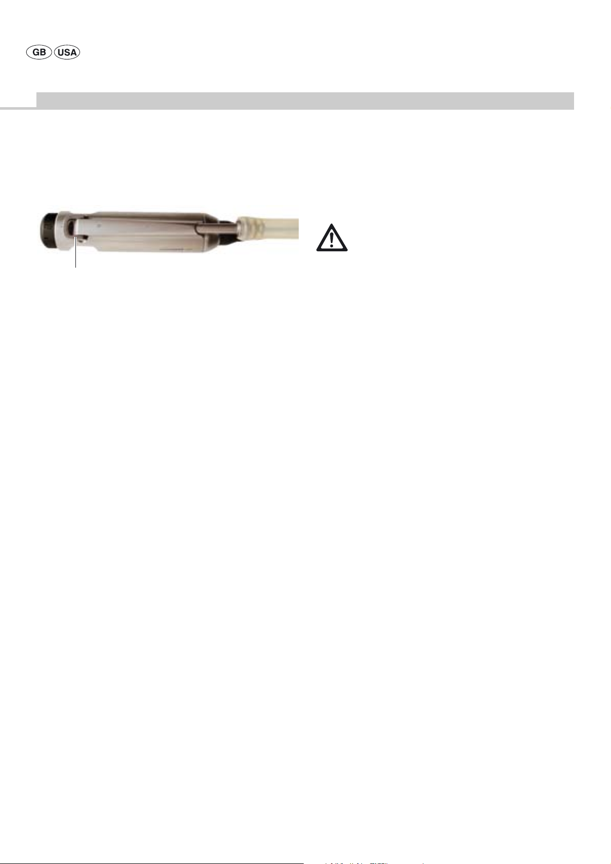
Aesculap Power Systems
microspeed® uni motor system
Setting the suction control device
36
Fig. 24
Legend
36 Suction control lever
The suction power control is continuously adjustable through the suction
control lever.
In position "O", suction is interrupted between the blade and the suction
device (no fluid drainage via the blade).
In position "I", suction is effective at full power according to the setting.
Note
The blade can get blocked at low suction power. This can be remedied by
setting the device to full suction power for a short period.
¾ Adjust suction control lever 36 to the required suction power.
4.3.3 Setting up and operating the microspeed® uni mini
pistol handpiece GD684
Risk of injury and damage due to long Kirschner wires!
¾ Use a sleeve when working with long Kirschner wires.
WARNING
Notes
The pistol handpiece can be locked against inadvertent actuation by gently
pressing and turning the upper trigger by 90°.
The pistol handpiece cannot be used with a foot control.
Working with an attached saw handpiece is only possible in the standard
operating mode.
The instruction menu allows changing motor type-specific settings (slow-
down and speed-up ramps, selection of oscillating or tapping mode), see
chapter Instruction menu.
The motor can only operated if:
• any motor connected to the other motor connection socket is inactive.
The following settings cannot be changed while motor 32 is running:
• Motor speed range upper limit
• Operating mode
All settings will be saved on exit from the settings mode.
Pistol handpiece GD684 supports two operating modes:
• Standard operating mode
• Oscillating or tapping mode
Changing the settings in the Device settings menu on the control unit
Note
The setting range and the step width for the speed range upper limit depend
on the selected operating mode, see chapter Technical specifications.
The speed range upper limit can be changed only in the standard operating
mode and only through the control unit.
The coolant pump can be activated, and the delivery rate can only be
changed, via the control unit.
Selecting the motor speed range upper limit
Note
The motor speed range upper limit can only be selected in the standard
operating mode.
The set motor speed range upper limit is indicated in the respective motor
control field in display 2 and can be adjusted via the touch control keys.
¾ To increase the motor speed range upper limit: press key to increase the
motor speed range upper limit.
¾ To reduce the motor speed range upper limit: press key to reduce the
motor speed range upper limit.
28
Page 31

Setting/activating the coolant pump delivery rate
Coolant pump 4 is activated and deactivated via the control key in the
respective motor control field.
The same control key also serves as a status indicator:
• The symbol displayed on a white background means that the pump is
switched off.
• The symbol displayed on a green background means that the pump is
switched on.
¾ To increase the delivery rate: press the key to increase the delivery rate
in the pump control field.
¾ To reduce the delivery rate: press the key to reduce the delivery rate in
the pump control field.
Selecting the operating mode
Standard operating mode
Pistol handpiece GD684 runs in standard mode if:
• the control unit recognizes that a pistol handpiece GD684 is
connected,
• "oscillating or tapping mode" was selected in the Instruction menu, but
not activated through the pistol handpiece.
The symbol “Oscillating or tapping mode” is displayed in the motor control
field.
Selecting Oscillating or tapping mode in the Instruction menu
¾ Call up Instruction menu in display 2: press control key “Instruction
menu” (arrow A).
A
Fig. 25
Oscillating or tapping mode
Note
In this operating mode, the motor speed range upper limit cannot be
changed via the touch control field on the control unit.
On system power-up, the oscillating or tapping mode is by default
deactivated and has to be activated again through the pistol handpiece.
The preselected setting in the Instruction menu is saved and remains in
memory even through subsequent system restarts.
Pistol handpiece GD684 will operate in “Oscillating or tapping mode” if:
• "Oscillating or tapping mode" was selected in the Instruction menu,
• this mode is activated through the pistol handpiece.
The symbol “display for oscillating or tapping mode active" is illuminated
in the motor control field.
Legend
A Arrow
A
Fig. 26
Legend
A Arrow
29
Page 32

Aesculap Power Systems
microspeed® uni motor system
¾ Call up menu “Motor settings”: press control key “Motor” (arrow A) in
the “Settings” field.
A
Fig. 27
Legend
A Arrow
¾ Call up menu ”Setting” for pistol handpiece GD684: press control key
“GD684” (arrow A).
¾ To pre-select “Oscillating or tapping mode”: press control key B.
¾ Save selection: press control key C.
¾ Exit the Instruction menu: press control key D.
¾ The symbol “Display for oscillating or tapping mode" (arrow A) is
illuminated in the motor control field.
A
AB C D
Fig. 28
Legend
A Display for oscillating or tapping mode
B Control keys for Oscillating or tapping mode “YES”
C Control key "Save setting"
The control key "Save setting" will be highlighted by a green
background whenever a setting was changed. Once the change has
been saved by pressing this control key, the control key will be
displayed on a white background.
D Control key "EXIT"
To exit from the Instruction menu
Fig. 29
Legend
A Arrow
30
Page 33

Activating the pistol handpiece
Fig. 30
Legend
33 Pistol handpiece
34 Upper trigger
35 Lower trigger
34
35
33
Oscillating or tapping mode
¾ For selecting the Oscillating or tapping mode in the Instruction menu,
see chapter Selecting Oscillating or tapping mode in the Instruction
menu.
¾ To activate the Oscillating or tapping mode:
press and hold down upper trigger 34 for three seconds.
Control unit 1 issues an acoustic signal.
The symbol “Display for oscillating or tapping mode active" is
illuminated in the motor control field.
Standard operating mode
¾ To activate right rotation: press lower trigger 35.
The motor speed is proportional to the actual trigger travel.
The motor direction indicator for right rotation is illuminated in the
motor control field.
Pistol handpiece 33 runs clockwise.
¾ To activate left rotation: First pull upper trigger 34, then lower
trigger 35.
The motor direction indicator for left rotation is illuminated in the
motor control field.
Pistol handpiece 33 runs counterclockwise.
Control unit 1 issues an acoustic signal.
¾ To reverse the motor direction: press upper trigger 34 with lower
trigger 34 already pressed.
The motor direction indicator for right rotation is illuminated in the
motor control field.
Pistol handpiece 33 runs clockwise.
The direction indicator for left rotation is illuminated and pistol
handpiece 33 reverses its direction of rotation.
Control unit 1 issues an acoustic signal.
Fig. 31
The keys for increasing or reducing the speed range upper limit are
faded out as, in this operating mode, the speed range upper limit
cannot be changed via the touch control field on control unit 1.
¾ To activate left rotation:
press upper trigger 34 with lower trigger 35 already pressed.
The motor direction indicator for left rotation is illuminated in the
motor control field.
Pistol handpiece 33 runs counterclockwise.
Control unit 1 issues an acoustic signal.
¾ To activate tapping:
press lower trigger 35 within the first half of its total travel range.
The motor direction indicators for left and right rotation in the motor
control field light up alternately.
Pistol handpiece 33 alternately runs counterclockwise and clockwise,
with the clockwise angle of rotation always larger than the
counterclockwise angle of rotation.
¾ To activate oscillating operation:
press lower trigger 35 within the second half of its total travel range.
The motor direction indicators for left and right rotation in the motor
control field light up alternately.
Pistol handpiece 33 runs counterclockwise and clockwise alternately.
31
Page 34

Aesculap Power Systems
microspeed® uni motor system
¾ To deactivate the Oscillating or tapping mode:
press and hold down upper trigger 34 for three seconds.
Control unit 1 issues an acoustic signal.
Fig. 32
The symbol “Display for oscillating or tapping mode" is illuminated in
the motor control field.
4.4 Settings in the Instruction menu
Note
The Instruction menu can only be called up when no motor is being
operated.
Motor operation will be blocked while the Instruction menu is active.
The Instruction menu is divided into two categories:
• Information:
Call-up of information on the error conditions issued on the display
(error list) and on the software version installed
• Setting:
To change specific settings; subdivided into the sections “Device
settings” and “Motor” (type).
All settings can be reset to the factory settings by pressing the control
key "Factory setting".
¾ To call up the Instruction menu:
press control key “Instruction menu”.
¾ To call up submenus:
press the respective control keys.
A
B
C
Fig. 33
Legend
A Section “Information”
B Control key "Info error list":
Calling up the submenu "Information on the error conditions issued on
the display"
C Display of “Software version”
D Section “Setting”
E Control key “Device setting”:
Calling up the submenu “Device-specific settings”
F Control key “Motor”:
Calling up the submenu “Motor (type)-specific settings”
G Control key “Factory setting”:
Reset, restoring factory settings (see chapter Factory settings)
H Control key "EXIT":
To exit from the Instruction menu
D
E
F
G
H
32
Page 35

4.4.1 Submenu information on the error conditions shown on
the display
¾ Press control key “Info error list” in menu “Information/Setting”.
A
B
C
Fig. 34
Legend
A Text field:
In this field the chapter “Troubleshooting list”, Malfunctions with
error numbers, is displayed
B Control key "Scroll up":
press this key to scroll up through the text.
If this key is pressed at the beginning of the text, the display jumps to
the end of the text
C Control key "Scroll down":
press this key to scroll down through the text.
If this key is pressed at the end of the text, the display jumps to the
beginning of the text
D Control key "Change to higher menu level"
(to submenu “Device-specific settings”)
E Control key "EXIT":
To exit from the Instruction menu
D
E
4.4.2 Submenu Device-specific settings
Device-specific settings are:
• Language setting
• Volume of acoustic alarm/notification signal
¾ Press control key “Device setting” in menu “Information/Setting”.
B
C
Fig. 35
Legend
A Control key "Language":
Call up submenu for language setting
B Control key "Volume":
Call submenu for setting the volume of the acoustic alarm/
notification signal
C Control key "Change to higher menu level":
(to Information/Setting menu)
D Control key "EXIT":
To exit from the Instruction menu
D
33
Page 36

Aesculap Power Systems
microspeed® uni motor system
Language setting
¾ Press control key “Language” in submenu “Setting”.
A
A
A
C
B
Fig. 36
Legend
A Control key for language display:
Select language; the selected language will be displayed on a green
background
B Control key "Save setting":
The control key "Save setting" will be highlighted by a green
background whenever a setting was changed. Pressing this key will
cause the change to be saved. Once the change has been saved, the
control key will be displayed on a white background.
C Control key "Change to higher menu level"
(to submenu Device-specific settings)
D Control key "EXIT":
To exit from the Instruction menu
Setting the volume of acoustic alarm/notification signals
¾ Press control key “Setting” in submenu “Device setting”.
A
B
C
D
D
Fig. 37
E
Legend
A Qualitative bar display of the volume to be set
B Control keys “Change volume”
C Control key “Volume”:
To call up an acoustic signal at the presently set volume
D Control key "Save setting":
The control key "Save setting" will be highlighted by a green
background whenever a setting was changed.
Pressing this key will cause the change to be saved. Once the change
has been saved, the control key will be displayed on a white
background.
E Control key "Change to higher menu level"
(to submenu Device-specific settings)
F Control key "EXIT":
To exit from the Instruction menu
F
34
Page 37

4.4.3 Submenu Motor (type)-specific settings
This submenu allows specific settings for every motor type described in
the present instructions for use.
¾ Press control key “Motor” in menu “Information/Setting”.
Motor (type)-specific settings GD674, GD676, GD677, GD678,
GD679
For these motor types, the slow-down and speed-up ramps can be
adjusted.
¾ Press control key “Motor” (e.g. GD678).
A
Fig. 38
Legend
A Control keys ”Motor type”:
Select a motor type
B Control key "Change to higher menu level":
(to Information/Setting menu)
C Control key "EXIT":
To exit from the Instruction menu
A
B
C
D
B
C
I
Fig. 39
E
F
G
D
H
Legend
A Symbol for “Speed up” ramp
B Qualitative bar display of the speed-up ramp to be set
C Control keys for changing the speed-up ramp
D Control key "Save setting":
The control key "Save setting" will be highlighted by a green
background whenever a setting was changed. Pressing this key will
cause the change to be saved. Once the change has been saved, the
control key will be displayed on a white background.
E Symbol for “Slow down” ramp
F Qualitative bar display of the slow-down ramp to be set
G Control keys for changing the slow-down ramp
H Control key "EXIT":
To exit from the Instruction menu
I Control key "Change to higher menu level":
(to submenu Motor (type)-specific settings)
35
Page 38

Aesculap Power Systems
microspeed® uni motor system
Motor (type)-specific settings shaver handpiece GD682
The following settings are available for the shaver handpiece:
• Slow-down and speed-up ramps
• Oscillation frequency (= duration of left-right rotation, in seconds) and
speed-up ramp in oscillating operation (for Shaving mode)
¾ Press control key for motor type GD 682.
Adjust slow-down and speed-up ramps:
A
B
C
D
Fig. 40
J
I
E
F
G
D
H
Legend
A Symbol for “Speed up” ramp
B Qualitative bar display of the speed-up ramp to be set
C Control keys for changing the speed-up ramp
D Control key "Save setting":
The control key "Save setting" will be highlighted by a green
background whenever a setting was changed. Pressing this key will
cause the change to be saved. Once the change has been saved, the
control key will be displayed on a white background.
E Symbol for “Slow down” ramp
F Qualitative bar display of the slow-down ramp to be set
G Control keys for changing the slow-down ramp
H Control key "EXIT":
To exit from the Instruction menu
I Control key "Change to higher menu level":
(to submenu Motor (type)-specific settings)
J Control key "MORE":
Call up of submenu "Set oscillation frequency and speed-up ramp in
oscillating operation” (for Shaving mode of operation)
Setting the oscillation frequency and speed-up ramp for oscillating
operation in the “Shaving” mode:
A
B
C
F
B
D
B
E
Fig. 41
Legend
A Symbol for oscillating operation
B Control keys for changing the oscillation frequency/speed-up ramp
C Oscillation frequency display
D Symbol for “Speed up” ramp
E Qualitative bar display of the speed-up ramp to be set
F Control key "Save setting":
The control key "Save setting" will be highlighted by a green
background whenever a setting was changed. Press this key to save
the changed setting. Once the change has been saved, the control key
will be displayed on a white background.
G Control key "Change to higher menu level":
(to submenu Motor(type)-specific settings/Motor GD682/Set the
slow-down and speed-up ramps)
H Control key "EXIT":
To exit from the Instruction menu
G
B
F
H
36
Page 39

Motor (type)-specific settings pistol handpiece GD684
The following settings are available for the pistol handpiece:
• Slow-down and speed-up ramps
• Oscillating or tapping mode “Yes/No”
• Rotation angle in Oscillating or tapping mode
¾ Press control key “Motor” (motor type GD684) in menu “Information/
Setting”.
K Control keys for changing the speed-up ramp
L Qualitative bar display of the speed-up ramp to be set
To set the rotation angle for Oscillating or tapping mode:
¾ Press control key “MORE”.
E
F
E
K
L
K
A
B
C
F
Fig. 42
D
D
E
Legend
A Symbol for “Speed up” ramp
B Symbol for “Slow down” ramp
C Symbol for Oscillating or tapping mode
D Control keys for oscillating mode, "Yes" and "No"
On activation of "Yes" the control key "MORE" will be displayed.
If "Yes" is selected and saved via control key E, the symbol "Oscillating
or tapping mode" will be displayed in the motor control field after
exiting the Instruction menu, if a pistol handpiece is connected.
E Control key "Save setting":
The control key "Save setting" will be highlighted by a green
background whenever a setting was changed. Pressing this key will
cause the change to be saved. Once the change has been saved, the
control key will be displayed on a white background.
F Control key "Change to higher menu level":
(to submenu Motor (type)-specific settings)
G Control key "EXIT":
To exit from the Instruction menu
H Control key "MORE":
Call-up of submenu "Set rotation angle in oscillating or tapping
mode”
I Qualitative bar display of the slow-down ramp to be set
J Control keys for changing the slow-down ramp
G
A
B
E
C
J
E
D
I
H
E
Fig. 43
Legend
A Symbol for settings for oscillating operation:
Changing the angle of rotation for oscillating operation.
B Field for settings for tapping operation
In this field the tool rotation angle for tapping can be changed. Angle
adjustment for right rotation (forward) and angle adjustment for left
rotation (backward).
C Symbol for right rotation
D Symbol for left rotation
E Control keys for changing the angle of rotation
F Display of the angle of rotation to be set
G Control key "Change to higher menu level":
(to submenu Motor(type)-specific settings/Motor GD684/Set slowdown and speed-up ramps, Oscillating or tapping mode Yes/No)
H Control key "EXIT":
To exit from the Instruction menu
I Control key "Save setting":
The control key "Save setting" will be highlighted by a green
background whenever a setting was changed. Pressing this key will
cause the change to be saved. Once the change has been saved, the
control key will be displayed on a white background.
F
I
G
E
H
37
Page 40

Aesculap Power Systems
microspeed® uni motor system
5. Processing
Note
Observe all relevant national regulations and standards with regard to
processing.
Note
For patients with Creutzfeldt-Jakob disease (CJD), suspected CJD or
possible variants of CJD, observe the relevant national regulations
concerning the reprocessing of the products.
Note
Up-to-date information on processing can be found on the Aesculap
Extranet at www.aesculap-extra.net.
Note
Processing of accessories such as handpieces, tools and tubing is described
in the respective instructions for use and product care advisories. Do not
process products that are intended for single use only.
5.1 Processing the microspeed® uni control unit with
cooling unit GD670 and microspeed® uni foot
control devices GD668/GD671
Damage to, or destruction of the product caused by
mechanical cleaning/disinfecting!
CAUTION
5.1.1 Cleaning/Disinfection
DANGER
CAUTION
¾ Always clean and disinfect the product manually, never
in a machine.
¾ Do not sterilize the product under any circumstances.
Risk of electric shock and fire!
¾ Unplug the device before cleaning it.
¾ Do not use flammable or explosive cleaning and
disinfecting agents.
¾ Make certain that no fluids will penetrate the product.
Damage to the product due to inappropriate cleaning or
disinfecting agents!
¾ Only use a cleaning/disinfecting agent that is approved
for surface cleaning. Follow the manufacturer’s
instructions for the respective cleaning/disinfecting
agent.
¾ Use cleaning/disinfecting agents that are suitable for surface cleaning
of the product.
¾ Always follow the manufacturers’ instructions regarding concentration
and exposure time.
¾ Avoid encrustation of residues/proteins (e.g. caused by aldehyde/
alcohol).
¾ Only use bactericidal, fungicidal and virucidal disinfecting agents.
¾ Never immerse the product in water or detergent.
¾ Never boil or mechanically disinfect the product.
¾ Let any fluid that penetrated the product drain out immediately.
38
Page 41

5.1.2 Manual cleaning/disinfecting
¾ Apply cleaning and disinfectant solution.
¾ Wipe away cleaning and disinfectant solution with a sponge or cloth
that has been moistened in clean water.
¾ Inspect surfaces, cavities, lumens and openings for visible debris. If
necessary, repeat the cleaning/disinfection process.
¾ Dry the product with a lint-free cloth.
5.1.3 Control, care and inspection
¾ Inspect the product after each cleaning and disinfecting cycle to be
sure it is clean, functional and undamaged.
5.1.4 Storage
¾ Store reprocessed products under conditions as germ-free as possible,
in a dry, dark, cool and dust-protected room.
5.2 Processing the microspeed® uni motors GD674,
GD676, GD677, GD678, GD679 and motor cables
GD672 and GD673
5.2.1 Preparations
¾ Prior to first mechanical cleaning/disinfection: Mount ECCOS® storage
device GB578R (for GD674, GD676, GD677, GD678, GD679) and
GB689R (for GD672, GD673) in a suitable basket tray (e.g. JF214R).
¾ Mount the storage devices in such a way that the cables can be coiled
in a circle with a bending radius of not less than 10 cm. Do not kink
the cables.
¾ Separate the motor from the motor cable prior to reprocessing.
¾ Carry out non-fixating/NaCl-free pre-cleaning immediately after use.
¾ Remove all attached components such as adapters, tubes, etc.
¾ Reprocess the product immediately after use.
¾ Do not clean the product by ultrasound treatment under any
circumstances.
¾ Put away the product in dry condition.
5.2.2 Cleaning/Disinfection
Damage to the product due to inappropriate cleaning/
disinfecting agents and/or excessive temperatures!
CAUTION
¾ Only use cleaning and disinfecting agents that do not
affect softeners (e.g. silicone), according to the
manufacturers’ instructions for use.
¾ Do not exceed the maximum allowable cleaning
temperature of 55 °C.
¾ Use cleaning/disinfecting agents that are suitable for the product.
Always follow the manufacturer’s instructions regarding
concentration, temperature and exposure time.
¾ Avoid encrustation of residues/proteins (e.g. caused by aldehyde/
alcohol).
¾ Only use bactericidal, fungicidal and virucidal disinfecting agents.
¾ Preferably use thermal disinfecting processes.
39
Page 42

Aesculap Power Systems
microspeed® uni motor system
5.2.3 Mechanical cleaning/disinfecting
Pre-cleaning
¾ Thoroughly pre-rinse under running water.
Cleaning
¾ Place the product in its proper position in the ECCOS® storage device
immediately after use.
¾ Process the product in a single-chamber cleaning/disinfecting machine
without ultrasound treatment. Follow the instructions provided by the
manufacturer of the machine.
¾ Carry out the processing cycle:
– Use an appropriate neutral, alkaline or mildly alkaline cleaning/
disinfecting agent according to the manufacturer’s instructions.
– Do not exceed the maximum cleaning temperature of 55 °C.
– Wash the product for at least 3 min.
– Neutralize if necessary.
– Carry out intermediate rinse for at least 1 min.
– Carry out intensive final rinse with distilled, demineralized or fully
desalinated water.
– For thermal disinfection: Rinse with distilled, demineralized or fully
desalinated water for 5 min, at 93 °C.
– Complete the program with a drying phase of at least 10 min at a
temperature of not more than 120 °C.
¾ After completion of the mechanical cleaning/disinfecting cycle,
inspect for visible debris all surfaces and places that are difficult to
access.
¾ Clean manually if necessary.
5.2.4 Manual cleaning/disinfecting
¾ Use an appropriate neutral, alkaline or mildly alkaline cleaning/
disinfecting agent according to the manufacturer’s instructions.
¾ Do not clean the product by ultrasound treatment under any
circumstances.
¾ Do not immerse the product in any fluid. Allow any fluid that has
penetrated the device to run out immediately.
¾ Clean all surfaces with a soft nylon brush and a suitable cleaning/
disinfecting agent.
¾ Remove encrusted debris with a soft nylon brush. Do not use harsh
cleaning agents or metal brushes.
¾ Thoroughly brush and rinse surfaces under running water.
¾ Carry out intensive final rinse with distilled, demineralized or fully
desalinated water.
¾ Inspect for visible debris all surfaces and places that are difficult to
access. If necessary, repeat the cleaning/disinfection process.
¾ Dry the product with a lint-free cloth.
¾ Make certain that lumens and channels are dried, too.
5.2.5 Control, care and inspection
¾ Allow the product to cool down to room temperature.
¾ Inspect the product after each cleaning and disinfecting cycle to be
sure it is clean, functional and undamaged and does not show atypical
running noises, overheating or excessive vibrations.
¾ Set aside the product if it is damaged.
¾ After cleaning and before sterilization, always lubricate the motor with
oil spray STERILIT® HI GA536:
– Fully insert the spray can adapter on the nipple at the rear end of the
motor.
– Hold the spray can in a vertical position and push down the spray
nozzle valve until oil extrudes at the front end of the handpiece
coupling of the motor.
– Wipe away any excess oil.
40
5.2.6 Packaging
¾ Always follow the instructions for use of the respective storage devices
(e.g. instructions for use TA009721 for the Aesculap ECCOS® storage
system).
¾ Insert the product in its proper position in the ECCOS® storage device,
or put it on a tray in such a way that the product is protected against
damage. Observe the weight limit for each tray/container.
¾ Package trays appropriately for the sterilization process (e.g. in
Aesculap sterile containers).
¾ Make certain that the product is wrapped in such a way that
recontamination of the product in the period between reprocessing
and reuse will be prevented.
Page 43

5.2.7 Sterilization method and parameters
Damage to motor cables GD672 and GD673 caused by
sterilization in sterilizers of small volume! Hot wall
CAUTION
¾ Sterilize with steam, taking note of the following:
Carry out steam sterilization via an approved steam sterilization
procedure (e.g. sterilizer in conformance with EN 285/ANSI/AAMI/
ISO 11134-1993, ANSI/AAMI ST46-1993 and validated in
conformance with EN ISO 17665 or EN 554/ISO 13683). In the
fractioned vacuum process, sterilization must be carried out using the
134 °C/2 bar program with a minimum holding time of 5 minutes.
Note
Steam sterilization at 134 °C for a holding time of 18 min can adversely
affect the service life of the product.
¾ Make certain that the motor cables are not kinked or coiled up too
tightly. The coil radius has to be larger than 10 cm.
¾ When sterilizing several products at the same time in one steam
sterilizer: Make sure that the maximum allowable load capacity of the
steam sterilizer, as specified by the manufacturer, is not exceeded.
surfaces (>150 °C) in the sterilizer can damage the
motor cable!
¾ Protect the motor cable (e.g. by wrapping it in a
cloth).
5.2.10 Maintenance
To ensure reliable operation, Aesculap recommends that maintenance be
performed after 300 reprocessing cycles, at least once per year.
For services to this end, please contact your national B. Braun/Aesculap
agency, see chapter Technical Service.
5.3 Processing the microspeed® uni shaver handpiece
GD682
5.3.1 Preparations
¾ Prior to first mechanical cleaning/disinfection: Mount ECCOS® storage
GB580R in a suitable tray (e.g. JF214R).
¾ Pre-clean the product, if necessary.
¾ Reprocess the product immediately after use.
¾ Do not immerse the shaver handpiece.
¾ Do not clean the shaver handpiece through ultrasound treatment.
¾ Use cleaning/disinfecting agents that are suitable for the product.
Always follow the manufacturer’s instructions regarding
concentration, temperature and exposure time.
¾ Avoid encrustation of residues/proteins (e.g. caused by aldehyde/
alcohol).
¾ Only use bactericidal, fungicidal and virucidal disinfecting agents.
¾ Preferably use thermal disinfecting processes.
5.2.8 Sterilization for the US market
• Sterilization of the device may be accomplished by steam.
• Aesculap does not recommend the device be sterilized by “Flash” or
chemical sterilization.
• Surgical instruments may also be placed within an Aesculap rigid sterilization container (sterile container) for processing under generally
accepted hospital in-use conditions.
The recommended sterilization parameters are as follows:
Sterilization
method
Pre-vacuum 270—275 °F 4 min 4 min
WARNING for the US market
If this device is/was used in a patient with, or suspected of having
Creutzfeldt-Jakob Disease (CJD), the device cannot be reused and
must be destroyed due to the inability to reprocess or sterilize to
eliminate the risk of crosscontamination.
Temp.
Minimum exposure time
Wrapped
In a sterile container
system
5.2.9 Storage
¾ Store processed products under conditions as germ-free as possible, in
a dry, dark, cool and dust-protected room.
5.3.2 Mechanical cleaning/disinfecting
¾ Place the product in its proper position in ECCOS® storage GB580R
immediately after use.
¾ Connect the rinsing tube of he washing machine at tube olive 38 of
shaver handpiece 37.
¾ Turn suction control lever 36 of shaver handpiece 37 to the Ι-position.
¾ Seal all rinsing tubes of the washing machine that are not used.
¾ Carry out the processing cycle:
– Use an appropriate neutral, alkaline or mildly alkaline cleaning/
disinfecting agent according to the manufacturer’s instructions.
– Do not exceed the maximum washing temperature of 55 °C.
– Wash the product for at least 3 min.
– Neutralize if necessary.
– Carry out intermediate rinse for at least 1 min.
– Carry out intensive final rinse with distilled, demineralized or fully
desalinated water.
– For thermal disinfection: Rinse for 5 min at 93 °C, with distilled,
demineralized or fully desalinated water.
– Conclude the program with a drying period of at least 10 min at a
temperature not exceeding 120 °C.
¾ After completion of the mechanical cleaning/disinfecting cycle,
inspect the surfaces, the driver and the suction channel for visible
debris.
¾ Clean manually if necessary.
41
Page 44

Aesculap Power Systems
microspeed® uni motor system
5.3.3 Manual cleaning/disinfecting
¾ Use an appropriate neutral, alkaline or mildly alkaline cleaning/
disinfecting agent according to the manufacturer’s instructions. Do
not immerse the product in any fluid.
¾ Remove encrusted materials with a soft nylon brush. Do not use harsh
cleaning agents or metal brushes.
¾ Clean difficult-to-access areas with soft round plastic brushes of
fitting diameter.
¾ Carry out intensive final rinse with distilled, demineralized or fully
desalinated water.
¾ Inspect surfaces and difficult-to-access areas for visible debris. If
necessary, repeat the cleaning/disinfection process.
¾ Use a lint-free cloth or a compressed-air gun for drying the product.
¾ Make certain that difficult-to-access areas and blind holes are dried,
too.
5.3.4 Control, care and inspection
¾ Allow the product to cool down to room temperature.
¾ Inspect the product after each cleaning and disinfecting cycle to be
sure it is clean, functional and undamaged.
¾ Check that the suction control lever can be moved.
¾ Spray-lubricate the friction surfaces of the unlocking sleeve and the
suction control lever, using Aesculap STERILIT® oil spray.
5.3.5 Packaging
¾ Always follow the instructions for use of the respective packaging and
storage equipment (e.g. instructions for use TA009721 for Aesculap
ECCOS® storage system).
¾ Insert the product in its proper position in ECCOS® storage GB580R, or
put it on a tray in such a way that the product is protected against
damage. Observe the weight limit for each tray/container.
¾ Pack trays in a way that is appropriate for the sterilization process (e.g.
in Aesculap sterile containers).
¾ Pack the product in such a way that the packaging will prevent
recontamination of the product in the period between reprocessing
and reuse.
5.3.6 Sterilization method and parameters
Damage to motor cables GD672 and GD673 caused by
sterilization in sterilizers of small volume! Hot wall
CAUTION
¾ Sterilize with steam, taking note of the following:
Carry out steam sterilization via an approved steam sterilization
procedure (e.g. sterilizer in conformance with EN 285/ANSI/AAMI/
ISO 11134-1993, ANSI/AAMI ST46-1993 and validated in
conformance with EN ISO 17665 or EN 554/ISO 13683). In the
fractioned vacuum process, sterilization must be carried out using the
134 °C/2 bar program with a minimum holding time of 5 minutes.
Note
Steam sterilization at 134 °C for a holding time of 18 min can adversely
affect the service life of the product.
¾ Make certain that the motor cables are not kinked or coiled up too
tightly. The coil radius has to be larger than 10 cm.
¾ When sterilizing several products at the same time in one steam
sterilizer: Make sure that the maximum allowable load capacity of the
steam sterilizer, as specified by the manufacturer, is not exceeded.
surfaces (>150 °C) in the sterilizer can damage the
motor cable!
¾ Protect the motor cable (e.g. by wrapping it in a
cloth).
5.3.7 Sterilization for the US market
• Sterilization of the device may be accomplished by steam.
• Aesculap does not recommend the device be sterilized by “Flash” or
chemical sterilization.
• Surgical instruments may also be placed within an Aesculap rigid sterilization container (sterile container) for processing under generally
accepted hospital in-use conditions.
The recommended sterilization parameters are as follows:
Sterilization
method
Pre-vacuum 270—275 °F 4 min 4 min
Temp.
Minimum exposure time
Wrapped
In a sterile container
system
42
WARNING for the US market
If this device is/was used in a patient with, or suspected of having
Creutzfeldt-Jakob Disease (CJD), the device cannot be reused and
must be destroyed due to the inability to reprocess or sterilize to
eliminate the risk of crosscontamination.
5.3.8 Storage
¾ Store reprocessed products under conditions as germ-free as possible,
in a dry, dark, cool and dust-protected room.
Page 45

5.3.9 Maintenance
To ensure reliable operation, Aesculap recommends the shaver handpiece
GD682 to be serviced after 300 processing cycles or at least once a year.
For the respective services, please contact your national B. Braun/
Aesculap agency, see chapter Technical Service.
5.4 Processing the microspeed® uni mini pistol
handpiece GD684
5.4.1 Preparations
¾ Prior to first mechanical cleaning/disinfection: Mount ECCOS® storage
device GB579R in a suitable tray (e.g. JF214R). Mount the storage
device in such a way that the cables can be coiled in a circle with a
bending radius of not less than 10 cm. Do not kink the cable.
¾ Carry out non-fixating/NaCl-free pre-cleaning immediately after use.
¾ Remove all attached components such as adapter, sleeve, etc.
¾ Reprocess the product immediately after use.
¾ Do not clean the product by ultrasound treatment under any
circumstances.
¾ Put away the product in dry condition.
5.4.3 Mechanical cleaning/disinfecting
AB
33
Fig. 44
Legend
A ECCOS® rinsing adapter
B Tube
33 microspeed® uni mini pistol handpiece
5.4.2 Cleaning/Disinfection
Damage to the product due to inappropriate cleaning/
disinfecting agents and/or excessive temperatures!
CAUTION
¾ Use cleaning/disinfecting agents that are suitable for the product.
¾ Avoid fixating of residues/proteins (e.g. caused by aldehyde/alcohol).
¾ Only use bactericidal, fungicidal and virucidal disinfecting agents.
¾ Preferably use thermal disinfecting processes.
¾ Only use cleaning and disinfecting agents that do not
affect softeners (e.g. silicone), according to the
manufacturer’s instructions for use.
¾ Do not exceed the maximum allowable cleaning
temperature of 55 °C.
Always follow the manufacturer’s instructions with regard to
concentration, temperature and exposure time.
Pre-cleaning
¾ For cleaning the cannulation, use special cleaning brush TA011327.
Cleaning
¾ Place the product in its proper position in ECCOS® storage device
GB579R immediately after use.
¾ Process the product in a single-chamber cleaning/disinfecting machine
without ultrasound treatment. Follow the instructions provided by the
manufacturer of the machine.
¾ Engage ECCOS® rinsing adapter at the rear of microspeed® uni mini
pistol handpiece 33 and connect it to the rinsing device of the singlechamber cleaning/disinfecting machine via a suitable tube.
¾ Carry out the processing cycle:
– Use an appropriate neutral, alkaline or mildly alkaline cleaning/
disinfecting agent according to the manufacturer’s instructions.
– Do not exceed the maximum cleaning temperature of 55 °C.
– Clean for at least 3 min.
– Neutralize if necessary.
– Apply intermediate rinse for at least 1 min.
– Carry out intensive final rinse with distilled, demineralized or fully
desalinated water.
– For thermal disinfection: Rinse with distilled, demineralized or fully
desalinated water for 5 min, at 93 °C.
– Complete the program with a drying phase of at least 10 min at a
temperature of not more than 120 °C.
¾ After completion of the mechanical cleaning/disinfecting cycle,
inspect for visible debris all surfaces and places that are difficult to
access.
¾ Clean manually if necessary.
43
Page 46

Aesculap Power Systems
microspeed® uni motor system
5.4.4 Manual cleaning/disinfecting
¾ Do not clean the product by ultrasound treatment under any
circumstances.
¾ Use an appropriate neutral, alkaline or mildly alkaline cleaning/
disinfecting agent according to the manufacturer’s instructions.
¾ Do not immerse the product in any fluid. Allow any fluid that has
penetrated the device to run out immediately.
¾ Clean all surfaces with a soft plastic brush and a suitable cleaning/
disinfecting agent.
¾ Remove encrusted debris with a soft nylon brush. Do not use harsh
cleaning agents or metal brushes.
¾ For cleaning the cannulation, use special cleaning brush TA011327.
¾ Thoroughly brush and rinse surfaces under running water.
¾ Carry out intensive final rinse with distilled, demineralized or fully
desalinated water.
¾ Inspect for visible debris all surfaces and places that are difficult to
access. If necessary, repeat the cleaning/disinfection process.
¾ Dry the product with a lint-free cloth.
¾ Make certain that lumens and channels are dried, too.
5.4.5 Control, care and inspection
¾ Allow the product to cool down to room temperature.
¾ Inspect the product after each cleaning and disinfecting cycle to be
sure it is clean, functional and undamaged and does not show atypical
running noises, overheating or excessive vibrations.
¾ Set aside the product if it is damaged.
5.4.6 Packaging
¾ Always follow the instructions for use of the respective storage devices
(e.g. instructions for use TA009721 for the Aesculap ECCOS® storage
system).
¾ Insert the product in its proper position in the ECCOS® storage device,
or on a tray in such a way that the product is protected against
damage. Observe the weight limit for each tray/container.
¾ Package trays appropriately for the sterilization process (e.g. in
Aesculap sterile containers).
¾ Pack the product in such a way that the packaging will prevent
recontamination of the product in the period between reprocessing
and reuse.
5.4.7 Sterilization method and parameters
Damage to the pistol handpiece caused by sterilization
in sterilizers of insufficient volume! Hot wall surfaces
CAUTION
¾ Sterilize with steam, taking note of the following:
Carry out steam sterilization via an approved steam sterilization
procedure (e.g. sterilizer in conformance with EN 285/ANSI/AAMI/
ISO 11134-1993, ANSI/AAMI ST46-1993 and validated in
conformance with EN ISO 17665 or EN 554/ISO 13683). In the
fractioned vacuum process, sterilization must be carried out using the
134 °C/2 bar program with a minimum holding time of 5 minutes.
Note
Steam sterilization at 134 °C for a holding time of 18 min can adversely
affect the service life of the product.
¾ Make certain that the motor cables are not kinked or coiled up too
tightly. The coil radius has to be larger than 10 cm.
¾ When sterilizing several products at the same time in one steam
sterilizer: Make sure that the maximum allowable load capacity of the
steam sterilizer, as specified by the manufacturer, is not exceeded.
(>150 °C) in the sterilizer can damage the motor
cable!
¾ Protect the motor cable (e.g. by wrapping it in a
cloth).
5.4.8 Sterilization for the US market
• Sterilization of the device may be accomplished by steam.
• Aesculap does not recommend the device be sterilized by “Flash” or
chemical sterilization.
• Surgical instruments may also be placed within an Aesculap rigid sterilization container (sterile container) for processing under generally
accepted hospital in-use conditions.
The recommended sterilization parameters are as follows:
Sterilization
method
Pre-vacuum 270—275 °F 4 min 4 min
Temp.
Minimum exposure time
Wrapped
In a sterile container
system
44
WARNING for the US market
If this device is/was used in a patient with, or suspected of having
Creutzfeldt-Jakob Disease (CJD), the device cannot be reused and
must be destroyed due to the inability to reprocess or sterilize to
eliminate the risk of crosscontamination.
5.4.9 Storage
¾ Store processed products under conditions as germ-free as possible, in
a dry, dark, cool and dust-protected room.
Page 47

5.4.10 Maintenance
To ensure reliable operation, Aesculap recommends the product to be
serviced after every 300 processing cycles or at least once a year.
For services to this end, please contact the B. Braun/Aesculap agency in
your country, see chapter Technical Service.
6. Maintenance
Send in the microspeed® uni motor system with its accessories for annual
inspection by the manufacturer, to the following address:
Aesculap Technischer Service
Am Aesculap-Platz
78532 Tuttlingen / Germany
Phone: +49 7461 95-2700
Fax: +49 7461 16-2887
E-mail: ats@aesculap.de
Or in the US:
Aesculap Inc.
Attn. Aesculap Technical Services
615 Lambert Pointe Drive
Hazelwood, MO 63042
Aesculap Repair Hotline
Phone: +1 800 214-3392
Fax: +1 314 895-4420
45
Page 48

Aesculap Power Systems
microspeed® uni motor system
7. Troubleshooting list
7.1 Malfunctions with error numbers
As soon as an error status is detected, an error window will pop up on the
display and an acoustic warning will be issued.
In the event a malfunction cannot be remedied as described below:
¾ Have component(s) repaired by the manufacturer.
Malfunction Message displayed Cause Detection/Remedy
Error 1 Error 1 Key actuation (softkey actuation):
More than one key was pressed at the same
time
Error 2 Error 2 Key (softkey) held down for too long:
Control key pressed for longer than 20 s
Error 3 Error 3 – Foot-Control Pedal(s) of the foot control pressed during
automatic self-test
Both pedals of foot control GD671 pressed Press one pedal only
Plug contacts of foot control unclean Clean the plug contacts
Foot control defective Replace foot control
Error 4 Error 4 – Hand-Control Lever of motor cable GD673 or trigger of
pistol handpiece GD684 actuated during
automatic test
Motor cable GD673 defective Replace motor cable
Pistol handpiece GD684 defective Replace pistol handpiece
Error 5 Error 5 – Select Motor Speed request from foot control while the
motor is locked by the motor release switch
on motor cable GD672 (position "OFF")
Motor cable GD672 defective Replace motor cable
Error 5 – Select only one Motor Speed request from foot control while two
motors are released for operation the motor
release switch on motor cable GD672
(position "ON")
Motor cable GD672 defective Replace motor cable
Error 5 – Connect only one Shaver Speed request from foot control while two
shaver handpieces GD682 are connected to
the control unit
Only press one key
Do not press any key for longer than 20 s
Release pedal(s)
Pressing both pedals is only allowed in
operating mode "Shave" in conjunction
with the shaver handpiece
Release lever or trigger, respectively
Set motor release switch on motor cable to
position "ON"
Release the required motor through motor
release switch (position "ON")
Block the motor that is not required
through motor release switch (position
"OFF")
Connect only one shaver handpiece GD682
to the control unit
46
Page 49

Malfunction Message displayed Cause Detection/Remedy
Error 6 Error 6 – Motor Speed request through foot or hand control
Connect a motor to the control unit
while no motor is connected to the control
unit
Motor defective Replace motor
Motor cable GD672 or GD673 defective Replace motor cable
Error 6 – Motor/Hallsensor Control unit detects malfunction in Hall
Replace motor
system of the motor.
Only for motors GD674, GD678, GD679,
GD682 and GD684
Motor cable GD672 or GD673 defective Replace motor cable
Error 6 – Motor blocked Motor blocked Stop motor actuation and release blockage
Motor defective Replace motor
Error 7 Error 7 - Motor overheated Temperature:
Motor has overheated, see chapter Overload
Allow motor to cool down, or replace
motor
cut-out
Error 8 Error 8 – Power Fail Power supply error:
Verify correct mains voltage
The mains voltage is outside the defined
range
Error 9 Error 9 Current cannot be applied properly to the
Replace motor or motor cable, respectively
motor
Error 10 Error 10 – Pump Pump:
Check position of the tubing
Mechanical blockage of the pump
Error 11 Error 11 – Internal Power-Supply
e.g. (+35 V)
Internal supply voltage:
- 35-V motor voltage monitor
- +15-V voltage monitor
Switch on and off the control unit
If the error reoccurs, have the control unit
repaired by the manufacturer
- -15-V voltage monitor
- +5-V voltage monitor
Error 12 Error 12 – System Error
System error: E
Error 13 Error 13 – Battery Battery fault
2
PROM, DSP, controller
Have battery replaced by the manufacturer
(Battery on processor card GD670801)
Error 14 Error 14 – External Data-
Communication
Error 15 Error 15 – Power-Circuit Motor power stage
External data communication error
(in connection with RS232, CAN, Ethernet)
Switch on and off the control unit
If the error reoccurs, have the control unit
repaired by the manufacturer
47
Page 50

Aesculap Power Systems
microspeed® uni motor system
7.2 Other malfunctions
Malfunction Cause Finding Remedy
The motor does not run No power to control unit Control unit not connected to
mains power or not switched on
(Power ON indicator dark, black
display)
Fuses blown Power ON indicator dark, black
display
Control unit cannot be operated
The motor does not run
Connected handpiece does not run Handpiece blocked Motor runs when the handpiece is
No coolant flow Nozzle clogged Coolant pump works Clean nozzle
Pistol handpiece does not run Protection against inadvertent
Internal monitoring system
blocking the system
Tubing inserted incorrectly Coolant pump works Install tubing correctly, see chapter
Coolant pump motor defective Coolant pump does not work Have pump motor repaired by
switch-on activated
Control unit not operational
although it is used correctly
not connected
Upper trigger turned by 90° Turn back upper trigger
Connect control unit to mains
power, and switch it on
Replace fuses, see chapter Fuse
change
Switch on and off the control unit
If the error reoccurs, have the
control unit repaired by the
manufacturer
Have handpiece repaired by
manufacturer
System set-up
manufacturer
48
Page 51

7.3 Fuse change
Fatal injury from electric shock!
Open components can hold life-threatening mains voltage.
DANGER
Allowable fuses:
2 x IEC 127 - T 6.3 A breaking capacity H (1 500 A)
¾ Unplug the device before changing the fuses!
¾ Unlock lug at fuse holder 13 , using a small screwdriver.
¾ Remove fuse holder 13.
¾ Change both fuses.
¾ Reinsert fuse holder 13 so that it audibly engages in its proper
Note
If the fuses blow frequently, the device is defective and needs to be
repaired; see Technical Service.
¾ Pull the mains plug before replacing the fuse sets.
position.
8. Technical Service
For service, maintenance or repairs, contact your national B. Braun/
Aesculap agency.
Modifications carried out on medical technical equipment may result in
loss of guarantee/warranty rights and forfeiture of applicable licenses.
Service addresses
Aesculap Technischer Service
Am Aesculap-Platz
78532 Tuttlingen / Germany
Phone: +49 7461 95-2700
Fax: +49 7461 16-2887
E-mail: ats@aesculap.de
Or in the US:
Aesculap Inc.
Attn. Aesculap Technical Services
615 Lambert Pointe Drive
Hazelwood, MO 63042
Aesculap Repair Hotline
Phone: +1 800 214-3392
Fax: +1 314 895-4420
Other service addresses can be obtained from the address indicated above.
9. Accessories/Spare parts
9.1 Accessories
9.1.1 microspeed® uni motors, motor cables and foot control
devices
Designation Art. no.
microspeed® uni mini 100 motor, mini-Line coupling GD674
microspeed® uni Hi 150 motor, Hi-Line coupling GD676
microspeed® uni Hi 100 motor, Hi-Line coupling GD677
microspeed® uni micro 150 motor, micro-Line coupling GD678
microspeed® uni micro 100 motor, micro-Line coupling GD679
microspeed® uni shaver handpiece GD682
microspeed® uni mini pistol handpiece, mini-Line
coupling
Protective sleeve (for microspeed® uni mini pistol
handpiece)
Auxiliary wrench for mini-Line coupling GB186209
microspeed® uni motor cable for foot control GD672
microspeed® uni motor cable with hand control GD673
microspeed® uni foot control, two pedals GD671
microspeed® uni foot control, one pedal GD668
9.1.2 Cooling unit
Designation Art. no.
Tubing set, reusable GA385
Tubing set, single-use GA391
Tubing set, single-use, for microspeed® uni GA392SU
Spike for 500-ml infusion bottles with rubber plug GA383R
Spike for 1 000-ml infusion bottles with rubber plug GA382R
Spike for 1 000-ml infusion bottles with Euro thread GA381R
Bottle holder GD412804
9.1.3 Other components
Designation Art. no.
microspeed® uni sterile shield for GD670 GD421
Mobile stand for microspeed® uni, adjustable height GA411
Mobile stand for surgical devices GD416M
GD684
GD684225
49
Page 52

Aesculap Power Systems
microspeed® uni motor system
9.1.4 Power cord
Approved in Color Length (in m) Art. no.
Europe black 1.5 TE780
Europe black 5.0 TE730
UK black 5.0 TE734
USA, Canada, Japan gray 3.5 TE735
9.1.5 Maintenance, processing and service
Designation Art. no.
Drip feed oiler STERILIT® M GA059
Oil spray STERILIT® Hi GA536
Oil spray STERILIT® M GB149
Oil spray STERILIT® mini GB372
ECCOS® mount for microspeed® uni motors GB578R
ECCOS® mount for microspeed® uni mini pistol
handpiece
ECCOS® mount for microspeed® uni shaver handpiece GB580R
ECCOS® mount for microspeed® motor cable GB689R
Cleaning brush TA011327
Service manual microspeed® uni/arthro motor system TA022090
Service manual microspeed® uni motors and motor
cables
Service manual microspeed® uni shaver handpiece TA011910
Service manual microspeed® uni mini pistol handpiece TA011912
GB579R
TA011909
10. Technical specifications
10.1 Classification acc. to directive 93/42/EEC
Art. no. Designation Class
GD668 microspeed® uni foot control, one pedal
GD670 microspeed® uni control unit with cooling
unit
GD671 microspeed® uni foot control, two pedals
GD672 microspeed® uni motor cable for foot control
GD673 microspeed® uni motor cable with hand
control
GD674 microspeed® uni mini 100 motor, mini-Line
coupling
GD676 microspeed® uni Hi 150 motor, Hi-Line
coupling
GD677 microspeed® uni Hi 100 motor, Hi-Line
coupling
GD678 microspeed® uni micro 150 motor, micro-Line
coupling
GD679 microspeed® uni micro 100 motor, micro-Line
coupling
GD682 microspeed® uni shaver handpiece
GD684 microspeed® uni mini pistol handpiece, mini-
Line coupling
Ι
ΙΙa
Ι
Ι
Ι
ΙΙa
ΙΙa
ΙΙa
ΙΙa
ΙΙa
ΙΙa
ΙΙa
9.2 Spare parts
Designation Art. no.
Fuse set (melting) T 6.3 A TA021473
50
Page 53

10.2 microspeed® uni control unit with cooling unit
GD670
Mains voltage ranges
(Current intake)
Frequency 50-60 Hz
Protection class (acc. to IEC 60601-1)
Output voltage max. 35 V
Output current max. 8.5 A
Device fuse
Breaking capacity
Delivery rate of cooling pump
(at maximum dosage setting)
Weight 8.9 kg
Dimensions (L x W x H) 305 mm x 305 mm x 175 mm
Application component Type BF
EMC IEC 60601-1-2
Norms IEC 60601-1
10.2.1Factory settings
Parameter Setting/Status
100-120 V~ (4.2-3.2 A)
220–240 V~ (1.7–1.5 A)
Ι
T 6.3 A
H (1 500 A at 250 V/50 Hz)
approx. 80 ml/min
Parameter Setting/Status
Motor type-specific standard settings for
speed-up ramps
Motor type-specific standard settings for
slow-down ramps
Pump operation OFF
Pump flow 2/3-dosage
Language English
Acoustic alarm/notification signal max. volume
Standard
Standard
10.3Low-speed motors
10.3.1 Low-speed motors with micro-Line coupling
Art. no. Power output (in W) Design
GD678 150 Standard
GD679 100 Short
Motor speeds/setting
Note
The speed figures refer to motor speeds.
Motor speed range upper limit for highspeed motors GD676 and GD677
Motor speed range upper limit for lowspeed motors GD678 and GD679 with
micro-Line coupling
Motor speed range upper limit for lowspeed motors GD678 and GD679 with
micro-Line coupling
Motor speed range upper limit for lowspeed motors with mini-Line coupling
GD674 and pistol handpiece GD684
Oscillating or tapping mode (for pistol
handpiece GD684)
Rotation angle, oscillating mode
(for pistol handpiece GD684)
Rotation angle for tapping mode
(for pistol handpiece GD684)
Motor speed range upper limit for shaver
handpiece GD682, “Shaving” mode
Motor speed range upper limit for shaver
handpiece GD682, “Reaming” mode
Oscillation frequency in “Shaving” mode 1 s left, 1 s right
60,000 1/min
20,000 1/min
Saw program
16,000 1/min
16,000 1/min
deactivated (Instruction
menu)
210° clockwise, then 210°
counterclockwise at gear
reduction 16:1
270° clockwise, then 90°
counterclockwise at gear
reduction 16:1
800 1/min
6,000 1/min
Parameter Speed/Setting
Step width for speed range upper limit setting 1,000 1/min
Motor direction settings
(optical and acoustic notification for left
rotation)
Maximum speed range upper limit
- for motor GD678
- for motor GD679
Minimum speed range upper limit 1,000 1/min
Minimum speed setting 500 1/min
Factory setting 20,000 1/min
Saw program (with limited motor speed) max. 16,000 1/min
- right rotation
- left rotation
- 30,000 1/min
- max. 40,000 1/min
51
Page 54

Aesculap Power Systems
microspeed® uni motor system
10.3.2Low-speed motor with mini-Line coupling
Art. no. Power output (in W) Design
GD674 100 Standard
Motor speeds/setting
Note
The speed figures refer to motor speeds.
Parameter Speed/Setting
Step width for speed range upper limit setting 1,000 1/min
Motor direction settings
(optical and acoustic notification for left
rotation)
Maximum speed range upper limit 16,000 1/min
Minimum speed range upper limit 1,000 1/min
Minimum speed setting 500 1/min
Factory setting 16,000 1/min
- right rotation
- left rotation
10.4High-speed motors
10.4.1High-speed motors with Hi-Line coupling
Art. no. Power output (in W) Design
GD676 150 Standard
GD677 100 Short
Motor speeds/setting
Note
The speed figures refer to motor speeds.
Parameter Speed/Setting
Step width for speed range upper limit setting 5,000 1/min
Motor direction settings
(optical and acoustic notification for left
rotation)
Maximum speed range upper limit 80,000 1/min
Minimum speed range upper limit 10,000 1/min
Minimum speed setting 5,000 1/min
Factory setting 60,000 1/min
- right rotation
- left rotation
10.5microspeed® uni shaver handpiece GD682
Note
The speed figures refer to tool speeds.
Tool speeds/Setting Shaving mode
Parameter Speed/Setting
Step width for speed range upper limit setting 200 1/min
Motor direction settings - right rotation
- left rotation
- oscillating
Maximum speed range upper limit 5,000 1/min
Minimum speed range upper limit 200 1/min
Minimum speed setting approx. 100 1/min
Factory setting 800 1/min
Gear reduction 6:1
Oscillation frequency/factory setting 1 s left,
1 s right
Tool speeds/Setting Reaming mode
Parameter Speed/Setting
Step width for speed range upper limit setting
- within range 1,000 1/min to 3,000 1/min
- within range 3,000 1/min to 8,000 1/min -200 1/min
- 1,000 1/min
Motor direction settings
(optical and acoustic notification for left
rotation)
Maximum speed range upper limit 8,000 1/min
Minimum speed range upper limit 1,000 1/min
Minimum speed setting approx. 100 1/min
Factory setting 6,000 1/min
Gear reduction 6:1
- right rotation
- left rotation
52
Page 55

10.6 microspeed® uni mini pistol handpiece GD684
Motor speeds/setting
Parameter Speed/Setting
Step width for speed range upper limit setting 1,000 1/min
(for speed range
upper limits below
1,000 1/min in steps
of 250 1/min)
Motor direction settings
(optical and acoustic notification for left
rotation)
Maximum speed range upper limit 16,000 1/min
Minimum speed range upper limit 500 1/min
Minimum speed setting 300 1/min
Factory setting 16,000 1/min
Step width/setting for tapping
Parameter Setting
Step width settings 15°-angle at the tip
Setting range for right rotation 105–405°
Setting range for left rotation 45–345°
Factory setting 270° to the right
- right rotation
- left rotation
(16:1 gear)
90° to the left
11. Disposal
Note
The user institution is obliged to process the product before its disposal, see
chapter Processing.
Always adhere to national regulations when disposing of or recycling the
product or its components!
Products carrying this symbol are subject to separate
collection of electric and electronic devices. Within the
European Union, disposal is carried out without fees by
the manufacturer.
If you have any questions concerning the disposal of the product, please
contact your national B. Braun/Aesculap agency, see chapter Technical
Service.
12. Distributor in the US/Contact in Canada
for product information and complaints
Aesculap Inc.
3773 Corporate Parkway
Center Valley, PA 18034
USA
Note
The step width set for “to the right” (forward) must always be larger than
the step width set “to the left” (backward).
Step width/Settings oscillating operation
Parameter Setting
Step width settings 15°-angle at the tip
(16:1 gear)
Setting range 45–405°
Factory setting 210° (right and left)
Note
The step width settings for rotation “to the right” (forward) and “to the left”
(backward) are always identical.
53
Page 56

Aesculap Power Systems
microspeed® uni-Motorensystem
Legende
Legende erste Ausklappseite: Steuereinheit
1 microspeed® uni Steuereinheit mit Kühleinheit GD670
2 Display mit Touchbedienfeld
3 Entriegelungstasten
4 Kühlflüssigkeitspumpe
5 Motoranschlussbuchsen
6 Schalter Netz AUS
7 Schalter Netz EIN
8 Anzeige Netz EIN
9 Flaschenhalter
10 Aufnahme für Flaschenhalter
11 Lüftungsgitter
12 Gerätesteckdose
13 Sicherungshalter
14 Anschlussbuchse für Fußsteuerung
15 Stapelkonen
16 Feststellschraube
17 Anschluss für Potenzialausgleich
39 Die Benutzung dieser Anschlüsse ist ausschließlich dem
Hersteller vorbehalten
Legende zweite Ausklappseite: Fußsteuerungen, Motorkabel, Motoren
18 Funktionstaster Fußsteuerung
19 Rechtes Pedal
20 Linkes Pedal
21 microspeed
22 Motordrehrichtungsumschalter
23 Pedal
24 microspeed® uni Fußsteuerung ein Pedal GD668
25 Motorfreigabeschalter
26 Funktionstaster Handsteuerung
27 microspeed® uni Motorkabel mit Handsteuerung GD673
28 Entriegelungsflügel
29 Hebel
30 Motorfreigabeschalter
31 microspeed® uni Motorkabel für Fußsteuerung GD672
32 Motoren mit motorseitiger Steckverbindung
33 microspeed® uni mini Pistolenhandstück GD684
34 Oberer Drücker
35 Unterer Drücker
36 Saugregulierhebel
37 microspeed® uni Shaverhandstück GD682
38 Schlaucholive
® uni Fußsteuerung zwei Pedale GD671
Inhaltsverzeichnis
1. Sichere Handhabung . . . . . . . . . . . . . . . . . . . . . . . . . . . . . . . . . . 55
2. Gerätebeschreibung . . . . . . . . . . . . . . . . . . . . . . . . . . . . . . . . . . . 56
2.1 Lieferumfang. . . . . . . . . . . . . . . . . . . . . . . . . . . . . . . . . . . . . . . . . 56
2.2 Zum Betrieb erforderliche Komponenten . . . . . . . . . . . . . . . . . . 56
2.3 Verwendungszweck . . . . . . . . . . . . . . . . . . . . . . . . . . . . . . . . . . . 56
2.4 Funktionsweise . . . . . . . . . . . . . . . . . . . . . . . . . . . . . . . . . . . . . . . 56
2.4.1. Steuereinheit. . . . . . . . . . . . . . . . . . . . . . . . . . . . . . . . . . . . . . . . . 56
2.4.2. Bedien- und Anzeigeoberfläche . . . . . . . . . . . . . . . . . . . . . . . . . 56
2.4.3. Beschreibung der Bedienfelder am Display . . . . . . . . . . . . . . . . 57
2.4.4. Motorbedienfelder . . . . . . . . . . . . . . . . . . . . . . . . . . . . . . . . . . . . 57
2.4.5. Pumpenbedienfeld . . . . . . . . . . . . . . . . . . . . . . . . . . . . . . . . . . . . 58
2.4.6. Instruction-Menü . . . . . . . . . . . . . . . . . . . . . . . . . . . . . . . . . . . . . 58
2.4.7. Motorerkennung . . . . . . . . . . . . . . . . . . . . . . . . . . . . . . . . . . . . . . 59
2.4.8. Automatisches Speichern von Geräteeinstellungen. . . . . . . . . . 59
2.4.9. Überlastsicherung. . . . . . . . . . . . . . . . . . . . . . . . . . . . . . . . . . . . . 59
2.4.10. Kühlflüssigkeitspumpe . . . . . . . . . . . . . . . . . . . . . . . . . . . . . . . . 59
2.4.11. Motorkabel. . . . . . . . . . . . . . . . . . . . . . . . . . . . . . . . . . . . . . . . . . 59
2.4.12. Motoren . . . . . . . . . . . . . . . . . . . . . . . . . . . . . . . . . . . . . . . . . . . . 61
2.4.13. Fußsteuerungen. . . . . . . . . . . . . . . . . . . . . . . . . . . . . . . . . . . . . . 63
2.5 Symbole. . . . . . . . . . . . . . . . . . . . . . . . . . . . . . . . . . . . . . . . . . . . . 64
2.5.1. Symbole an der Steuereinheit . . . . . . . . . . . . . . . . . . . . . . . . . . . 64
2.5.2. Symbole an Fußsteuerungen, Motorkabel und Motor . . . . . . . . 64
2.5.3. Symbole im Display . . . . . . . . . . . . . . . . . . . . . . . . . . . . . . . . . . . 65
3. Vorbereiten und Aufstellen . . . . . . . . . . . . . . . . . . . . . . . . . . . . . 67
3.1 Vorbereiten . . . . . . . . . . . . . . . . . . . . . . . . . . . . . . . . . . . . . . . . . . 67
3.1.1. Steuereinheit am Fahrständer befestigen. . . . . . . . . . . . . . . . . . 67
3.1.2. Steuereinheit vom Fahrständer lösen . . . . . . . . . . . . . . . . . . . . . 67
3.1.3. Spannungsversorgung anschließen. . . . . . . . . . . . . . . . . . . . . . . 67
4. Arbeiten mit dem microspeed® uni-Motorensystem . . . . . . . . . 68
4.1 Bereitstellen . . . . . . . . . . . . . . . . . . . . . . . . . . . . . . . . . . . . . . . . . 68
4.1.1. Zubehör anschließen . . . . . . . . . . . . . . . . . . . . . . . . . . . . . . . . . . 68
4.1.2. Fußsteuerung an die Steuereinheit anschließen . . . . . . . . . . . . 68
4.1.3. Schlauchgarnitur anschließen . . . . . . . . . . . . . . . . . . . . . . . . . . . 69
4.1.4. Motorkabel an Steuereinheit anschließen . . . . . . . . . . . . . . . . . 69
4.1.5. Motoren (GD674, GD676, GD677, GD678 und GD679)
an Motorkabel anschließen . . . . . . . . . . . . . . . . . . . . . . . . . . . . . 70
4.1.6. Steuereinheit einschalten/Automatischer Einschaltcheck . . . . 70
4.1.7. Handstücke/Aufsätze/Schneidblätter anschließen. . . . . . . . . . . 70
4.2 Funktionsprüfung . . . . . . . . . . . . . . . . . . . . . . . . . . . . . . . . . . . . . 74
4.3 Bedienung . . . . . . . . . . . . . . . . . . . . . . . . . . . . . . . . . . . . . . . . . . . 75
4.3.1. Motoren GD674, GD676, GD677, GD678 und GD679
einstellen und bedienen . . . . . . . . . . . . . . . . . . . . . . . . . . . . . . . . 75
4.3.2. microspeed® uni Shaverhandstück GD682
einstellen und bedienen . . . . . . . . . . . . . . . . . . . . . . . . . . . . . . . . 78
4.3.3. microspeed® uni mini Pistolenhandstück GD684
einstellen und bedienen . . . . . . . . . . . . . . . . . . . . . . . . . . . . . . . . 80
4.4 Einstellungen im Instruction-Menü . . . . . . . . . . . . . . . . . . . . . . 84
4.4.1. Untermenü Informationen über die am Display
ausgegebenen Fehlerzustände. . . . . . . . . . . . . . . . . . . . . . . . . . . 85
4.4.2. Untermenü Gerätespezifische Einstellungen . . . . . . . . . . . . . . . 85
4.4.3. Untermenü Motor(typ)-spezifische Einstellungen . . . . . . . . . . . 87
5. Aufbereiten . . . . . . . . . . . . . . . . . . . . . . . . . . . . . . . . . . . . . . . . . . 90
5.1 microspeed® uni Steuereinheit mit Kühleinheit GD670 und
microspeed® uni Fußsteuerungen GD668/GD671 aufbereiten. . . .90
54
Page 57

5.1.1. Reinigung/Desinfektion. . . . . . . . . . . . . . . . . . . . . . . . . . . . . . . . . 90
5.1.2. Manuelle Reinigung/Desinfektion . . . . . . . . . . . . . . . . . . . . . . . . 91
5.1.3. Kontrolle, Pflege und Prüfung . . . . . . . . . . . . . . . . . . . . . . . . . . . 91
5.1.4. Lagerung . . . . . . . . . . . . . . . . . . . . . . . . . . . . . . . . . . . . . . . . . . . . 91
5.2 microspeed® uni Motoren GD674, GD676, GD677, GD678,
GD679 und Motorkabel GD672 und GD673 aufbereiten . . . . . . 91
5.2.1. Vorbereitung . . . . . . . . . . . . . . . . . . . . . . . . . . . . . . . . . . . . . . . . . 91
5.2.2. Reinigung/Desinfektion. . . . . . . . . . . . . . . . . . . . . . . . . . . . . . . . . 91
5.2.3. Maschinelle Reinigung . . . . . . . . . . . . . . . . . . . . . . . . . . . . . . . . . 92
5.2.4. Manuelle Reinigung/Desinfektion . . . . . . . . . . . . . . . . . . . . . . . . 92
5.2.5. Kontrolle, Pflege und Prüfung . . . . . . . . . . . . . . . . . . . . . . . . . . . 92
5.2.6. Verpackung . . . . . . . . . . . . . . . . . . . . . . . . . . . . . . . . . . . . . . . . . . 92
5.2.7. Sterilisieren . . . . . . . . . . . . . . . . . . . . . . . . . . . . . . . . . . . . . . . . . . 93
5.2.8. Lagerung . . . . . . . . . . . . . . . . . . . . . . . . . . . . . . . . . . . . . . . . . . . . 93
5.3 microspeed® uni Shaverhandstück GD682 aufbereiten . . . . . . . 93
5.3.1. Vorbereitung . . . . . . . . . . . . . . . . . . . . . . . . . . . . . . . . . . . . . . . . . 93
5.3.2. Maschinelle Reinigung/Desinfektion . . . . . . . . . . . . . . . . . . . . . . 93
5.3.3. Manuelle Reinigung/Desinfektion . . . . . . . . . . . . . . . . . . . . . . . . 94
5.3.4. Kontrolle, Pflege und Prüfung . . . . . . . . . . . . . . . . . . . . . . . . . . . 94
5.3.5. Verpackung . . . . . . . . . . . . . . . . . . . . . . . . . . . . . . . . . . . . . . . . . . 94
5.3.6. Sterilisieren . . . . . . . . . . . . . . . . . . . . . . . . . . . . . . . . . . . . . . . . . . 94
5.3.7. Lagerung . . . . . . . . . . . . . . . . . . . . . . . . . . . . . . . . . . . . . . . . . . . . 94
5.4 microspeed® uni mini Pistolenhandstück GD684 aufbereiten. . 95
5.4.1. Vorbereitung . . . . . . . . . . . . . . . . . . . . . . . . . . . . . . . . . . . . . . . . . 95
5.4.2. Reinigung/Desinfektion. . . . . . . . . . . . . . . . . . . . . . . . . . . . . . . . . 95
5.4.3. Maschinelle Reinigung . . . . . . . . . . . . . . . . . . . . . . . . . . . . . . . . . 95
5.4.4. Manuelle Reinigung/Desinfektion . . . . . . . . . . . . . . . . . . . . . . . . 96
5.4.5. Kontrolle, Pflege und Prüfung . . . . . . . . . . . . . . . . . . . . . . . . . . . 96
5.4.6. Verpackung . . . . . . . . . . . . . . . . . . . . . . . . . . . . . . . . . . . . . . . . . . 96
5.4.7. Sterilisieren . . . . . . . . . . . . . . . . . . . . . . . . . . . . . . . . . . . . . . . . . . 96
5.4.8. Lagerung . . . . . . . . . . . . . . . . . . . . . . . . . . . . . . . . . . . . . . . . . . . . 96
5.4.9. Wartung. . . . . . . . . . . . . . . . . . . . . . . . . . . . . . . . . . . . . . . . . . . . . 96
6. Wartung . . . . . . . . . . . . . . . . . . . . . . . . . . . . . . . . . . . . . . . . . . . . . 96
7. Fehler erkennen und beheben . . . . . . . . . . . . . . . . . . . . . . . . . . . 97
7.1 Störungen mit Fehlernummer . . . . . . . . . . . . . . . . . . . . . . . . . . . 97
7.2 Weitere Störungen . . . . . . . . . . . . . . . . . . . . . . . . . . . . . . . . . . . . 99
7.3 Sicherungswechsel . . . . . . . . . . . . . . . . . . . . . . . . . . . . . . . . . . . 100
8. Technischer Service . . . . . . . . . . . . . . . . . . . . . . . . . . . . . . . . . . . 100
9. Zubehör/Ersatzteile . . . . . . . . . . . . . . . . . . . . . . . . . . . . . . . . . . . 100
9.1 Zubehör . . . . . . . . . . . . . . . . . . . . . . . . . . . . . . . . . . . . . . . . . . . . 100
9.1.1. microspeed® uni Motoren, Motorkabel und Fußsteuerungen . . . 100
9.1.2. Kühleinheit. . . . . . . . . . . . . . . . . . . . . . . . . . . . . . . . . . . . . . . . . . 100
9.1.3. Weitere Komponenten . . . . . . . . . . . . . . . . . . . . . . . . . . . . . . . . 101
9.1.4. Netzkabel . . . . . . . . . . . . . . . . . . . . . . . . . . . . . . . . . . . . . . . . . . . 101
9.1.5. Pflege, Aufbereitung und Service. . . . . . . . . . . . . . . . . . . . . . . . 101
9.2 Ersatzteile . . . . . . . . . . . . . . . . . . . . . . . . . . . . . . . . . . . . . . . . . . 101
10. Technische Daten . . . . . . . . . . . . . . . . . . . . . . . . . . . . . . . . . . . . 101
10.1 Klassifizierung gemäß Richtlinie 93/42/EWG . . . . . . . . . . . . . . 101
10.2 microspeed® uni Steuereinheit mit Kühleinheit GD670. . . . . . 102
10.2.1. Werkseinstellungen. . . . . . . . . . . . . . . . . . . . . . . . . . . . . . . . . . . 102
10.3 Low-Speed-Motoren . . . . . . . . . . . . . . . . . . . . . . . . . . . . . . . . . 103
10.3.1. Low-Speed-Motoren mit micro-Line-Kupplung. . . . . . . . . . . . 103
10.3.2. Low-Speed-Motor mit mini-Line-Kupplung. . . . . . . . . . . . . . . 103
10.4 High-Speed-Motoren . . . . . . . . . . . . . . . . . . . . . . . . . . . . . . . . . 104
10.4.1. High-Speed-Motoren mit Hi-Line-Kupplung . . . . . . . . . . . . . . 104
10.5 microspeed® uni Shaverhandstück GD682 . . . . . . . . . . . . . . . . 104
10.6 microspeed® uni mini Pistolenhandstück GD684. . . . . . . . . . . 105
11. Entsorgung . . . . . . . . . . . . . . . . . . . . . . . . . . . . . . . . . . . . . . . . . 105
1. Sichere Handhabung
Lebensgefahr durch elektrischen Stromschlag!
¾ Steuereinheit darf keinesfalls durch den Anwender ge-
GEFAHR
Hinweis
Für die Handhabung der Produkte, die mit dem microspeed® uni-Motoren-
system verwendet werden, die Gebrauchsanweisungen dieser Produkte beachten. Die vorliegende Gebrauchsanweisung beschreibt au sschließlich die
Handhabung des “microspeed® uni-Motorensystems”.
¾ Vor der Anwendung des Produkts Funktionsfähigkeit und ordnungsge-
mäßen Zustand prüfen.
¾ Hinweise zur elektromagnetischen Verträglichkeit (EMV) beachten,
siehe TA022130.
¾ Um Schäden durch unsachgemäßen Aufbau oder Betrieb zu vermeiden
und die Garantie und Haftung nicht zu gefährden:
– Produkt nur gemäß dieser Gebrauchsanweisung verwenden.
– Sicherheitsinformationen und Instandhaltungshinweise beachten.
– Nur Aesculap-Produkte miteinander kombinieren.
¾ Produkt und Zubehör nur von Personen betreiben und anwenden las-
sen, die die erforderliche Ausbildung, Kenntnis oder Erfahrung haben.
¾ Gebrauchsanweisung für das OP-Personal zugänglich aufbewahren.
¾ Gültige Normen einhalten.
¾ Sicherstellen, dass die elektrische Installation des Raums den IEC-An-
forderungen entspricht.
¾ Netzverbindungen durch Ziehen am Stecker lösen, nie durch Ziehen am
Kabel.
¾ Steuereinheit und Motor nicht in explosionsgefährdeten Bereichen
einsetzen.
¾ Motor(en), Motorkabel, Schlauchgarnitur, Handstück(e) und Werkzeug
vor dem Einsatz steril aufbereiten.
¾ Handstücke nur mit den empfohlenen Drehzahlen betreiben.
öffnet werden.
¾ Produkt nur an ein Versorgungsnetz mit Schutzleiter an-
schließen.
55
Page 58

Aesculap Power Systems
microspeed® uni-Motorensystem
2. Gerätebeschreibung
2.1 Lieferumfang
Bezeichnung Art.-Nr.
microspeed® uni Steuereinheit mit Kühleinheit GD670
Flaschenhalter GD412804
Gebrauchsanweisung TA022089
Hinweis zur elektromagnetischen Verträglich-
keit (EMV)
2.2 Zum Betrieb erforderliche Komponenten
• microspeed® uni Steuereinheit mit Kühleinheit GD670
• Netzkabel
• Motor
• Motorkabel
(bei Verwendung von Motor mit motorseitiger Steckverbindung)
•Fußsteuerung
(bei Verwendung eines Motorkabels ohne Handsteuerung oder des
Shaverhandstücks)
•Flaschenhalter
(bei Verwendung der Kühlflüssigkeitspumpe)
• Schlauchgarnitur
(bei Verwendung der Kühlflüssigkeitspumpe)
• Chirurgiesauger
(bei Verwendung des Shaverhandstücks)
2.3 Verwendungszweck
Das microspeed® uni-Motorensystem ist ein Universalsystem sowohl in
Bezug auf das Anwendungsspektrum als auch auf die Systemzusammenstellung und die Nutzungsvielfalt.
Das microspeed® uni-Motorensystem wird in der Orthopädie/Traumatologie, Neurochirurgie, Wirbelsäulenchirurgie, Hand-/Fuß-Chirurgie, HNO-/
MKG-Chirurgie, plastischen Chirurgie und Arthroskopie eingesetzt.
Das microspeed® uni-Motorensystem kann komplett aus dem sterilen Bereich, wahlweise mit Fuß- oder Handsteuerung betrieben werden.
TA022130
2.4 Funktionsweise
Das microspeed® uni-Motorensystem besteht aus folgenden Komponenten:
• Einer universell verwendbaren Steuereinheit mit Kühlfllüssigkeitspumpe
• zwei Motoranschlusskabeln (mit und ohne Handsteuerung)
• einer Vielzahl verschiedener Motoren mit unterschiedlich ausgeführten
Kupplungen
• einem Pistolenhandstück
• einem Shaverhandstück
•zwei Fußsteuerungen
2.4.1 Steuereinheit
Die Steuereinheit 1 ist für ein Netzspannungsbereich von 100 V bis 240 V
und von 50 Hz bis 60 Hz konzipiert. Die Netzspannung wird zur Versorgung der Motoren in eine Schutzkleinspannung umgewandelt.
Die Steuereinheit 1 verfügt über zwei Motoranschlussbuchsen 5 zum Anschluss von zwei (unterschiedlichen) Motoren und einer Anschlussbuchse
für Fußsteuerung 14 (Geräterückseite).
An die Steuereinheit 1 können zeitgleich maximal angeschlossen sein:
• zwei Motoren und
• eine Fußsteuerung (GD668 oder GD671).
Hinweis
Zeitgleich keine zwei Shaverhandstücke GD682 anschließen.
Es kann zeitgleich nur ein Motor aktiviert werden.
Die Motoren mit motorseitiger Steckverbindung GD674, GD676, GD677,
GD678 und GD679 können sowohl mit Handsteuerung (Motorkabel
GD673) als auch mit Fußsteuerung GD668 oder GD671 (mit Motorkabel
GD672) verwendet werden.
Hinweis
Sind zwei Motoren ohne Handsteuerung an die Steuereinheit angeschlos-
sen (Motorkabel GD672), ist ein Motorbetrieb nur dann möglich, wenn der
Motorfreigabeschalter des Motors, der aktiviert werden soll, auf "ON" gestellt ist, während der andere Motor gesperrt ist (Motorfreigabeschalter
auf "OFF").
2.4.2 Bedien- und Anzeigeoberfläche
Das Display 2 zeigt zu jedem Zeitpunkt den aktuellen Gerätestatus (Betriebs- und Fehlerzustände) an. Das Display ist in Motorbedienfeld(er) und
Pumpenbedienfeld unterteilt. Durch Betätigen der Bedientasten können
die Geräte-Einstellparameter verändert werden.
Alle Symbole, die in den Motor- und Pumpenbedienfeldern verwendet
werden, siehe Kapitel Symbole im Display.
Durch Betätigen der Bedientaste "Instruction-Menü" wird das Instruction-Menü aufgerufen.
56
Page 59

2.4.3 Beschreibung der Bedienfelder am Display
A B
2.4.4 Motorbedienfelder
A
B
C
D
E
F
G
H
I
C
Abb. 1
Legende
A Motorbedienfeld(er)
B Pumpenbedienfeld
C Instruction-Menü
Das Display teilt sich in drei verschiedene Bedienfelder auf, die in den folgenden Kapiteln beschrieben werden.
Abb. 2
Legende
A Status-Anzeige und Bedientaste zum Freischalten (Symbol grün hin-
terlegt)/Sperren der Pumpe
B Anzeige der Aktivierungsart: Handsteuerung oder Fußsteuerung
C Eingestellte Drehzahlbereichsobergrenze
D Qualitative Anzeige der aktuellen Istdrehzahl
E Bedientasten zur Erhöhung bzw. Reduzierung der Drehzahlbereichs-
obergrenze
F Motordrehrichtungsanzeige
G Mit dem angeschlossenen Motortyp gewählte Betriebsart, z. B. Säge-
programm bei den Motoren GD678 und GD679
H Angeschlossener Motortyp
I Maximal wählbare Drehzahlbereichsobergrenze mit dem angeschlos-
senen Motortyp bzw. mit der gewählten Betriebsart
Jedem an die Steuereinheit 1 angeschlossenen Motor ist ein Motorbedienfeld zugeordnet.
Im Display 2 werden nur dann zwei Motorbedienfelder geöffnet, wenn
auch zwei Motoren 32 mit der Steuereinheit 1 verbunden sind.
Ist nur ein Motor angeschlossen, so wird nur ein Motorbedienfeld geöffnet.
Die Bedienfelder sind optisch eindeutig den zugehörigen Motoranschluss-
buchsen 5 zugewiesen.
57
Page 60

Aesculap Power Systems
A
C
microspeed® uni-Motorensystem
Ein Motorbedienfeld wird als aktives Bedienfeld angezeigt, wenn mit dem
Motorbedienfeld zugeordneten Motor:
• gearbeitet wird
• zuletzt gearbeitet wurde.
Wenn ein Motorbedienfeld freigeschaltet ist, erscheint das Symbol des an-
geschlossenen Motortyps grün hinterlegt.
2.4.5 Pumpenbedienfeld
2.4.6 Instruction-Menü
Hinweis
Das Instruction-Menü kann nur an der Steuereinheit abgerufen werden.
Durch Betätigen dieser Bedientaste wird das Instruction-Menü aufgerufen. Dort können Informationen über die am Display ausgegebenen Fehlerzustände und Geräteeinstellungen wie Spracheinstellung und Lautstärke
des Alarm-/Signaltons verändert werden.
Außerdem können Motortyp-spezifische Änderungen bzw. Voreinstellungen vorgenommen werden:
• Brems- und Beschleunigungsrampen zu jedem Motortyp
• Oszillierender bzw. Gewindeschneid-Betrieb (beim Pistolenhandstück
GD684)
• Oszillationsfrequenz und Beschleunigungsrampe im oszillierenden Be-
B
trieb (bei Betriebsart Shaven des Shaverhandstücks GD682)
• Reset: Wiederherstellen der Werkseinstellungen
B
Abb. 3
Legende
A Status-Anzeige der Kühlflüssigkeitspumpe 4. Das Symbol ist grün hin-
terlegt, wenn die Pumpe aktiviert ist. Die Pumpe kann nur dann aktiviert
werden, wenn sie im entsprechenden Motorbedienfeld freigeschaltet
wurde und der Motor aktiviert ist.
B Bedientasten zur Erhöhung bzw. Reduzierung der Fördermenge
C Anzeige der vorgewählten Dosierstufe
Die vorgewählte Dosierstufe C bezieht sich auf den Motor, dessen Einstellparameter durch das freigeschaltete (weiß hinterlegte) Motorbedienfeld
angezeigt werden.
58
Page 61

2.4.7 Motorerkennung
Die Steuereinheit 1 erkennt den Motortyp, der an einer der Motoranschlussbuchsen 5 der Steuereinheit 1 angeschlossen wird und zeigt diesen
Typ im entsprechenden Motorbedienfeld des Displays 2 an. Die zuletzt mit
diesem Motortyp und an dieser Motoranschlussbuchse eingestellten Einstellparameter werden am Display 2 angezeigt.
Die Einstellparameter können entsprechend den motorspezifischen Bereichen am Display oder via Hand- bzw. Fußsteuerung (im Geräte-EinstellMenü) verändert werden, siehe Kapitel Technische Daten.
Das Motorbedienfeld des zuletzt aktivierten Motors wird immer hell dargestellt, während das Motorbedienfeld des nicht zuletzt aktivierten oder
gesperrten Motors grau hinterlegt dargestellt wird. Ist nur ein Motor an
die Steuereinheit 1 angeschlossen, erscheint dieses Bedienfeld hell, vorausgesetzt dieser Motor ist nicht gesperrt.
Sägeprogramm (nur in Verbindung mit den Low-Speed-Motoren
GD678 und GD679)
Bei diesem Programm wird die maximale Drehzahlbereichsobergrenze auf
16 000 1/min begrenzt. Die zuletzt mit dem Sägeprogramm verwendeten
Einstellparameter (gewählte Drehzahlbereichsobergrenze, Dosierstufe der
Kühlflüssigkeitspumpe 4) werden automatisch abgerufen.
2.4.8 Automatisches Speichern von Geräteeinstellungen
Die zuletzt mit diesem Motortyp, an dieser Motoranschlussbuchse, eingestellten Einstellparameter (Drehzahlbereichsobergrenze, Fördermenge
etc.), werden automatisch immer dann abgerufen, wenn nach einem Motorwechsel dieser Motortyp wieder an dieser Motoranschlussbuchse der
Steuereinheit 1 als angeschlossen erkannt wird.
Hinweis
Nach jedem Gerätestart sind sowohl die Kühlflüssigkeitspumpe als auch
motortyp-spezifische Sonderfunktionen wie z. B. das Sägeprogramm (bei
GD678 und GD679) oder der oszillierende bzw. Gewindeschneid-Betrieb
(bei GD684) grundsätzlich ausgeschaltet (auch dann, wenn sie zuvor freigeschaltet bzw. aktiviert waren). Beim Betätigen der Bedientaste "Werkseinstellung" im Instruction-Menü werden alle Einstellungen zurückgesetzt.
2.4.9 Überlastsicherung
Eine separat ausgeführte Temperaturüberwachung der angeschlossenen
Motoren soll diese vor einer thermischen Zerstörung schützen. Hierzu ist
in das Gerät ein Temperaturmodell integriert.
• 1. Stufe:
Wird über das Temperaturmodell auf eine Motortemperatur größer
75 °C und kleiner 90 °C geschlossen, ertönt ein Warnton und im Display blinkt die Anzeige "Temp. Motor". Bei weiterer Überlastung schaltet die Steuereinheit 1 in die 2. Stufe.
• 2. Stufe:
Wird eine Motortemperatur von 90 °C überschritten, so wird der Motor
abgeschaltet und im Display 2 erscheint die Meldung "Error 7 - Motor
overheated".
Nach einer Abkühlpause ist der Motor wieder einsatzbereit.
Wird der überhitzte Motor ausgetauscht, wird das Temperaturmodell zurückgesetzt und ein Weiterarbeiten ist möglich. Wir empfehlen einen
zweiten Motor bereitzuhalten.
2.4.10 Kühlflüssigkeitspumpe
Hinweis
Die Kühlflüssigkeitspumpe arbeitet nur bei laufendem Motor!
Nach jedem Gerätestart ist die Kühlflüssigkeitspumpe 4 grundsätzlich aus-
geschaltet (auch dann, wenn sie zuvor freigeschaltet war).
Die microspeed® uni-Steuereinheit 1 ist mit einer Kühlflüssigkeitspumpe 4
ausgestattet. Diese Kühlflüssigkeitspumpe dient ausschließlich zur Kühlung bzw. Spülung der Werkzeuge. Die Förderleistung in der höchsten Dosierstufe beträgt circa 80 ml pro Minute. Die Kühlflüssigkeitspumpe kann
sowohl im entsprechenden Motorbedienfeld als auch über die entsprechende Hand- bzw. Fußsteuerung aktiviert werden. Die Fördermenge ist
über das Pumpenbedienfeld oder über das Geräte-Einstell-Menü wählbar,
siehe Kapitel Untermenü Gerätespezifische Einstellungen.
Ausnahme: Beim Pistolenhandstück GD684 ist sowohl das Aktivieren der
Pumpe als auch das Verändern der Fördermenge nur über die entsprechenden Bedienfelder an der Steuereinheit möglich.
Es stehen 21 Dosierstufen zur Auswahl. In den Dosierstufen 1 bis 5 läuft
die Kühlflüssigkeitspumpe 4 im intermittierenden Betriebsmodus. Ein Einbzw. Ausschalten der Pumpe sowie ein Verändern der Fördermenge ist
auch bei aktiviertem Motor möglich. Wenn der Motor länger als
zwei Sekunden aktiviert war, wird ein Nachtropfen der Kühlflüssigkeit
durch eine spezielle Antriebssteuerung vermieden.
2.4.11 Motorkabel
Verletzungsgefahr durch unkontrollierte Eigendynamik des
Hautschleifhandstücks GB280 in Verbindung mit Motorka-
WARNUNG
Hinweis
Zum Anschließen der Motoren (mit motorseitiger Steckverbindung) GD674,
GD676, GD677, GD678 und GD679 an die Steuereinheit ist ein Motorkabel
erforderlich.
Das microspeed® uni-Motorensystem enthält ein Motorkabel für Fußsteuerung (GD672) und ein Motorkabel mit Handsteuerung (GD673). Beide
Motorkabel können in Verbindung mit allen Motoren genutzt werden, die
über eine motorseitige Steckverbindung verfügen. Zudem können beide
Motorkabel wahlweise an beide Motoranschlussbuchsen 5 angeschlossen
werden.
Hinweise
Die Auswahl des Motorkabels sollte in Abhängigkeit der Anwendung bzw.
des zu verwendenden Handstückes getroffen werden.
Beim Einsatz der Sägen GB128R, GB129, GB130R und des Motorkabels mit
Handsteuerung GD673 empfiehlt sich die Säge zur optimalen Handhabung
mit beiden Händen zu führen. Ist eine Führung der Säge mit einer Hand gewünscht, zur optimalen Handhabung das Motorkabel GD672 in Verbindung mit einer Fußsteuerung verwenden.
bel mit Handsteuerung GD673!
¾ Hautschleifhandstück GB280 nur mit Motorkabel
GD672 und Fußsteuerung verwenden.
59
Page 62

Aesculap Power Systems
microspeed® uni-Motorensystem
microspeed® uni Motorkabel für Fußsteuerung GD672
30
Abb. 4
Legende
30 Motorfreigabeschalter
Hinweis
Dieses Motorkabel kann nur in Verbindung mit einer Fußsteuerung verwen-
det werden.
Der auf dieses Motorkabel aufgesteckte Motor ist nur dann aktivierbar,
wenn der Motorfreigabeschalter 30 auf Position "ON" steht. Bei zeitgleicher
Verwendung von zwei Motorkabeln GD672 kann ein Motor nur dann aktiviert werden, wenn dieser freigeschaltet (Motorfreigabeschalter 30 auf Position "ON") ist, während der andere deaktiviert (Motorfreigabeschalter 30
auf Position "OFF") ist.
microspeed® uni Motorkabel mit Handsteuerung GD673
2629 25
Abb. 5
Legende
25 Motorfreigabeschalter:
Position "ON": Motor für Betrieb freigeschaltet
Position "OFF": Motor für Betrieb gesperrt
26 Funktionstaster Handsteuerung:
Kurzes Betätigen: Ein- und Ausschalten der Kühlflüssigkeitspumpe
Betätigen länger als drei Sekunden (bei nicht aktiviertem Motor):
Wechsel in das Geräte-Einstell-Menü, siehe Kapitel Einstellparameter
im Geräte-Einstell-Menü mit Handsteuerung ändern
29 Hebel:
Geber zur Drehzahlsollwertvorgabe
Hinweis
Bei Verwendung dieses Motorkabels ist ein Arbeiten mit einer Fußsteue-
rung nicht möglich.
Der auf dieses Motorkabel aufgesteckte Motor ist nur dann aktivierbar,
wenn der Motorfreigabeschalter auf Position "ON" gestellt ist.
60
Page 63

2.4.12 Motoren
Motoren mit motorseitiger Steckverbindung
Hinweis
Zum Anschließen von Motoren mit motorseitiger Steckverbindung an die
Steuereinheit ist ein Motorkabel GD672 oder GD673 erforderlich!
Abhängig vom Anwendungsgebiet stehen fünf Motortypen mit den drei
Standard-Aesculap-Kupplungssystemen Hi-Line, micro-Line (Intra Kupplungssystem gemäß DIN 13940 bzw. ISO 3964) und mini-Line zur Auswahl.
Die Motoren können sowohl im Rechtslauf als auch im Linkslauf betrieben
werden. Bei Linkslauf gibt die Steuereinheit 1 ein akustisches Signal aus.
Zu den Leistungsdaten und einstellbaren Parametern der einzelnen
Motortypen, siehe Kapitel Technische Daten.
Bei Motortypen GD678 und GD679 besteht die Möglichkeit, ein Sägeprogramm zu wählen. Bei diesem Sägeprogramm wird die maximale Drehzahlbereichsobergrenze auf 16 000 1/min begrenzt.
Motoren mit fest angeschlossenem Motorkabel GD682 und GD684
Hinweis
Die Motoren werden direkt an die Steuereinheit angeschlossen. Ein zusätz-
liches Motorkabel ist nicht erforderlich!
Zu den Leistungsdaten und einstellbaren Parametern der einzelnen Motor-
typen, siehe Kapitel Technische Daten.
microspeed® uni Shaverhandstück GD682
Hinweise
Gebrauchsanweisung der Schneidblätter TA011579 einhalten.
Nur Schneidblätter von Aesculap verwenden.
Bei Verwendung des Shaverhandstücks GD682 wird die Verwendung einer
Fußsteuerung GD671 und eines Chirurgiesaugers vorausgesetzt (z. B.
GF200 oder GF210).
Das Shaverhandstück GD682 kann verwendet werden, wenn:
• an der zweiten Motoranschlussbuchse ein Motor mit Motorkabel
GD673 angeschlossen ist, oder
• an der zweiten Motoranschlussbuchse ein Pistolenhandstück GD684
angeschlossen ist, oder
• an der zweiten Motoranschlussbuchse ein Motor mit Motorkabel
GD672 angeschlossen ist und der Motorfreigabeschalter dieses Kabels
auf "OFF" gestellt ist, oder
• nur ein Shaverhandstück GD682 an die Steuereinheit 1 angeschlossen
ist.
Für das Shaverhandstück GD682 gibt es zwei Arten von Schneidblättern:
Fräser- und Shaver-Schneidblätter.
Die Steuereinheit 1 erkennt, ob das aufgesteckte Schneidblatt ein Fräseroder Shaver-Schneidblatt ist und zeigt die entsprechende Betriebsart (Fräsen oder Shaven) im Display an.
Bei jedem Wechsel der Schneidblatt-Art wird ein akustisches Signal ausgegeben, während im Display das entsprechende Symbol im entsprechenden Motorbedienfeld erscheint.
Mit aufgestecktem Fräser-Schneidblatt kann im Rechts- und im Linkslauf,
jedoch nicht im oszillierenden Betrieb gearbeitet werden. Die maximale
Drehzahlbereichsobergrenze wird auf 8 000 1/min begrenzt. Das Symbol
für Betriebsart "Fräsen" erscheint im Motorbedienfeld.
Mit aufgestecktem Shaver-Schneidblatt kann sowohl im Rechts- und
Linkslauf als auch im oszillierenden Betrieb gearbeitet werden. Die maximale Drehzahlbereichsobergrenze wird auf 5 000 1/min begrenzt. Das
Symbol für Betriebsart “Shaven” erscheint im Motorbedienfeld.
36 38
Abb. 6
Legende
36 Saugregulierhebel:
Hebel zur stufenlosen Regulierung der Saugleistung
38 Schlaucholive:
Anschluss an den Chirurgiesauger mittels Saugschlauch
61
Page 64

Aesculap Power Systems
microspeed® uni-Motorensystem
microspeed® uni mini Pistolenhandstück GD684
34
35
Abb. 7
Legende
34 Oberer Drücker
35 Unterer Drücker
Hinweis
Das Pistolenhandstück wird durch leichtes Eindrücken und Drehen des obe-
ren Drückers um 90° gegen unbeabsichtigte Betätigungen gesperrt.
Das Pistolenhandstück kann nicht mit einer Fußsteuerung betrieben wer-
den.
Das Pistolenhandstück GD684 ist mit dem Aesculap-Kupplungssystem
mini-Line ausgerüstet.
Im Lieferumfang ist eine Schutzhülse enthalten. Diese Schutzhülse soll
beim Einsetzen von Spickdrähten vor Verletzungen und Sachschäden
schützen.
Das Pistolenhandstück GD684 kann in zwei Betriebsarten betrieben werden:
• Standard-Betrieb
• Oszillierender bzw. Gewindeschneid-Betrieb
Erkennt die Steuereinheit 1, dass ein Pistolenhandstück GD684 angeschlossen ist, arbeitet das Pistolenhandstück im Standard-Betrieb (Werkseinstellung). Ein Verändern der Geräte-Einstell-Parameter (Drehzahlbereichsobergrenze, Verändern der Fördermenge und aktivieren der Pumpe) ist nur über
das Touchbedienfeld der Steuereinheit 1 möglich. Über das InstructionMenü kann der oszillierende bzw. Gewindeschneid-Betrieb vorgewählt
werden. Die Anzeige für "Oszillierender bzw. Gewindeschneid-Betrieb" erscheint im entsprechenden Motorbedienfeld. Über den oberen Drücker wird
der oszillierende bzw. Gewindeschneid-Betrieb aktiviert. Es ertönt dann ein
akustisches Hinweissignal und die Anzeige für "Oszillierender bzw. Gewindeschneid-Betrieb aktiv" leuchtet im entsprechenden Motorbedienfeld. In
diesem Betriebsmodus kann die Drehzahlbereichsobergrenze nicht über das
Touchbedienfeld an der Steuereinheit 1 verändert werden.
Über den oberen Drücker kann der oszillierende bzw. GewindeschneidBetrieb wieder deaktiviert werden. Nach jedem Gerätestart und jedem erneuten Stecken des Pistolenhandstücks ist der oszillierende bzw. Gewindeschneid-Betrieb grundsätzlich deaktiviert und muss über das Pistolenhandstück neu aktiviert werden. Die vorgewählte Einstellung im
Instruction-Menü wird gespeichert und bleibt auch nach einem Geräteneustart erhalten.
Standard-Betrieb:
Arbeiten im Rechts- und im Linkslauf (bei Linkslauf gibt die Steuereinheit 1
ein akustisches Signal aus).
Drehrichtungswechsel bzw. Drücker für Linkslauf 34, siehe Abb. 7:
• Wird der obere Drücker 34 betätigt und gehalten, arbeitet das Pistolenhandstück bei Betätigung des unteren Drückers 35 im Linkslauf.
• Wird 34 nachträglich zu 35 betätigt, so wird die Motordrehrichtung
umgekehrt.
Drücker für Drehzahlregulierung 35:
• Geber zur Drehzahlsollwertvorgabe (Drehzahl ist proportional zum Betätigungshub).
• Wird nur 35 betätigt, arbeitet das Pistolenhandstück im Rechtslauf.
Oszillierender bzw. Gewindeschneid-Betrieb:
Aktivierung bzw. Deaktivierung des Betriebsmodus, siehe Abb. 7:
• Wird der obere Drücker 34 drei Sekunden betätigt, wird der Betriebsmodus aktiviert (bzw. deaktiviert).
Arbeiten im “Oszillierenden bzw. Gewindeschneid-Betrieb”:
• Wird der untere Drücker 35 in der ersten Hälfte des gesamten Betätigungshubs betätigt, arbeitet das Pistolenhandstück im Gewindeschneid-Betrieb. Die Drehzahl ist proportional zum Betätigungshub.
Gewindeschneid-Betrieb bedeutet: Winkelorientierte Drehung nach
rechts (vorwärts) und anschließend nach links (rückwärts), wobei der Winkel nach rechts immer größer ist als der Winkel nach links.
• Wird der untere Drücker 35 in der zweiten Hälfte des gesamten Betätigungshubs betätigt, arbeitet das Pistolenhandstück im oszillierenden
Betrieb. Die Drehzahl ist proportional zum Betätigungshub.
Oszillierender Betrieb bedeutet: Winkelorientierte Drehung nach rechts
und anschließend nach links, wobei der Winkel für beide Richtungen
gleich ist.
Wird der obere Drücker 34 zusätzlich zum unteren Drücker 35 betätigt,
arbeitet das Pistolenhandstück im Linkslauf.
62
Page 65

2.4.13 Fußsteuerungen
microspeed® uni Fußsteuerung zwei Pedale GD671
Hinweise
Das microspeed® uni-Motorensystem enthält zwei unterschiedlich ausge-
führte Fußsteuerungen (GD668 und GD671).
In Verbindung mit der Steuereinheit GD670 kann zeitgleich nur eine Fuß-
steuerung angeschlossen werden.
microspeed® uni Fußsteuerung ein Pedal GD668
18
22
23
Abb. 8
Legende
18 Funktionstaster Fußsteuerung:
Kurzes Betätigen: Ein- und Ausschalten der Kühlflüssigkeitspumpe
Betätigung länger als drei Sekunden (bei nicht aktiviertem Motor):
Wechsel in das Geräte-Einstell-Menü, siehe Kapitel Einstellparameter
im Geräte-Einstell-Menü mit Fußsteuerung ändern
22 Motordrehrichtungsumschalter:
Vorwahl Rechts- oder Linkslauf
23 Pedal:
Geber zur Drehzahlsollwertvorgabe
18
20
Abb. 9
Legende
18 Funktionstaster Fußsteuerung:
Kurzes Betätigen: Ein- und Ausschalten der Kühlflüssigkeitspumpe
Betätigung länger als drei Sekunden (bei nicht aktiviertem Motor):
Wechsel in das Geräte-Einstell-Menü, siehe Kapitel Einstellparameter
im Geräte-Einstell-Menü mit Fußsteuerung ändern
19 Rechtes Pedal:
Geber zur Drehzahlsollwertvorgabe im Rechtslauf
20 Linkes Pedal:
Geber zur Drehzahlsollwertvorgabe im Linkslauf
19
63
Page 66

Aesculap Power Systems
microspeed® uni-Motorensystem
2.5 Symbole
2.5.1 Symbole an der Steuereinheit
Gebrauchsanweisung einhalten
Anwendungsteil des Typs BF
Eingang von der Spülflasche (Kühlflüssigkeitspumpe)
Ausgang zum Handstück (Kühlflüssigkeitspumpe)
Förderrichtung (Kühlflüssigkeitspumpe)
Potenzialausgleichsanschluss
Sicherung
2.5.2 Symbole an Fußsteuerungen, Motorkabel und Motor
Funktionstaster
(Fußsteuerung GD668, GD671, Motorkabel GD673)
Motordrehrichtungsumschalter
Vorwahl Links- oder Rechtslauf
(Fußsteuerung GD668)
Pedal für Links- oder Rechtslauf
(entsprechend der am Motordrehrichtungsumschalter
vorgewählten Motordrehrichtung, Fußsteuerung GD668)
Pedal für Rechtslauf
(Fußsteuerung GD671)
Pedal für Linkslauf
(Fußsteuerung GD671)
Oszillierender Betrieb bei Betätigung beider Pedale
(nur in der Betriebsart "Shaven" in Verbindung mit dem
Shaverhandstück GD682 erlaubt, Fußsteuerung GD671)
Anästhesiemittelprüfung nach Klasse AP
(EN 60601-1)
(Fußsteuerung GD668 und GD671)
Gehäuseschutzart nach DIN EN 60529
IPX8
(Fußsteuerung GD668 und GD671)
Wechselstrom
Fußsteuerung
Kennzeichnung von Elektro- und Elektronikgeräten entsprechend Richtlinie 2002/96/EG (WEEE), siehe Kapitel
Entsorgung.
Entriegelung
(Motor GD674, GD682 und GD684)
Drehzahlsteuerung
(Motor GD684)
Rechts-/Linkslaufumschalter
(Motor GD684)
Oszillierender bzw. Gewindeschneid-Betrieb
(Motor GD684)
Sicherung gegen unbeabsichtigtes Betätigen
(Motor GD684)
64
Page 67

2.5.3 Symbole im Display
Anzeige-Symbole in den Motorbedienfeldern
(Gewählte) Drehzahlbereichsobergrenze
(Beispiel 20 000 1/min)
GD676 microspeed® uni Hi 150 Motor (High-SpeedMotor; 150 W; Kupplungssystem: Hi-Line (XS)) angeschlossen
Wenn der Motor aktivierbar (freigeschaltet) ist, erscheint
das Symbol mit grünem Hintergrund
Drehzahl in 1/min
Qualitative Anzeige der aktuellen Motor-Istdrehzahl
(beim Shaverhandstück GD682 Werkzeug-Istdrehzahl)
Darstellung des Symbols bei nicht aktiviertem Motor im
jeweiligen Motorbedienfeld; grau hinterlegt
Qualitative Anzeige der aktuellen Motor-Istdrehzahl
(beim Shaverhandstück GD682 Werkzeug-Istdrehzahl);
Aktiv bei Motorbetrieb
Drehrichtungsanzeige für Rechtslauf
bei nicht aktiviertem Motor oder wenn mit Fußsteuerung
GD668 kein Rechtslauf gewählt wurde;
Im inaktiven Motorbedienfeld ist dieses Symbol grau hinterlegt
Drehrichtungsanzeige für Rechtslauf
aktiv bei Motorbetrieb bzw. im Stand-By-Betrieb, wenn
diese Drehrichtung gewählt wurde und Fußsteuerung
GD668 an die Steuereinheit angeschlossen ist
Drehrichtungsanzeige für Linkslauf
bei nicht aktiviertem Motor oder wenn mit Fußsteuerung
GD668 kein Linkslauf gewählt wurde;
Im inaktiven Motorbedienfeld ist dieses Symbol grau hinterlegt
Drehrichtungsanzeige für Linkslauf
aktiv bei Motorbetrieb bzw. im Stand-By-Betrieb, wenn
diese Drehrichtung gewählt wurde und Fußsteuerung
GD668 mit Steuereinheit angeschlossen ist
Handsteuerung
aktiv, wenn angeschlossene Handsteuerung erkannt wird
Fußsteuerung
aktiv, wenn angeschlossene Fußsteuerung erkannt wird
und mindestens ein Motor nicht mit einer Handsteuerung
bestückt ist
Keine Fußsteuerung
aktiv, wenn weder Fußsteuerung noch Handsteuerung als
angeschlossen erkannt wird
GD677 microspeed® uni Hi 100 Motor (High-SpeedMotor; 100 W; Kupplungssystem: Hi-Line (XS)) angeschlossen
Wenn der Motor aktivierbar (freigeschaltet) ist, erscheint
das Symbol mit grünem Hintergrund
GD678 microspeed® uni micro 150 Motor (Low-SpeedMotor; 150 W; Kupplungssystem: micro-Line)
Wenn der Motor aktivierbar (freigeschaltet) ist, erscheint
das Symbol mit grünem Hintergrund
GD679 microspeed® uni micro 100 Motor (Low-SpeedMotor; 100 W; Kupplungssystem: micro-Line)
Wenn der Motor aktivierbar (freigeschaltet) ist, erscheint
das Symbol mit grünem Hintergrund
GD674 microspeed® uni mini 100 Motor (Low-SpeedMotor; 100 W; Kupplungssystem: mini-Line) angeschlossen
Wenn der Motor aktivierbar (freigeschaltet) ist, erscheint
das Symbol mit grünem Hintergrund
GD682 microspeed® uni Shaverhandstück angeschlossen
Wenn der Motor aktivierbar (freigeschaltet) ist, erscheint
das Symbol mit grünem Hintergrund
GD684 microspeed® uni mini Pistolenhandstück (Kupplungssystem: mini-Line) angeschlossen
Wenn der Motor aktivierbar (freigeschaltet) ist, erscheint
das Symbol mit grünem Hintergrund)
Betriebsart "Fräsen"
(nur in Verbindung mit Shaverhandstück GD682, wenn
keine Shaverspitze erkannt wird)
Betriebsart "Shaven"
(nur in Verbindung mit Shaverhandstück GD682, wenn
Shaverspitze erkannt wird)
65
Page 68

Aesculap Power Systems
microspeed® uni-Motorensystem
Oszillierender bzw. Gewindeschneid-Betrieb (nur in Verbindung mit Pistolenhandstück GD684)
Erscheint, wenn der oszillierende bzw. GewindeschneidBetrieb im Instruction-Menü freigeschaltet ist, jedoch
vom Pistolenhandstück nicht aktiviert wurde
Oszillierender bzw. Gewindeschneid-Betrieb aktiv
(nur in Verbindung mit Pistolenhandstück GD684)
Erscheint, wenn der oszillierende bzw. GewindeschneidBetrieb im Instruction-Menü freigeschaltet ist und vom
Pistolenhandstück aktiviert wird (drei-sekündiges Betätigen des oberen Drückers)
Anzeige-/Bedientasten-Symbole in den Motorbedienfeldern Anzeige-Symbole im Pumpenbedienfeld
Erhöhung der Drehzahlbereichsobergrenze
Reduktion der Drehzahlbereichsobergrenze
Status-Anzeige/Bedientaste des Sägeprogramms
Das Symbol kennzeichnet das deaktivierte Sägeprogramm, das nur in Verbindung mit den Motoren GD678
und GD679 wählbar ist
Status-Anzeige/Bedientaste des Sägeprogramms
Das Symbol kennzeichnet das aktivierte Sägeprogramm,
das nur in Verbindung mit den Motoren GD678 und
GD679 wählbar ist
Drehrichtungsanzeige für nicht gewählten Linkslauf und
Bedientaste zur Wahl des Linkslaufs
Das Symbol der Bedientaste und die Wahl der Motordrehrichtung am Display ist nur in Verbindung mit Handsteuerung GD673 gegeben
Drehrichtungsanzeige für gewählten Linkslauf und
Bedientaste zur Wahl des Linkslaufs
Das Symbol der Bedientaste und die Wahl der Motordrehrichtung am Display ist nur in Verbindung mit Handsteuerung GD673 gegeben
Drehrichtungsanzeige für nicht gewählten Rechtslauf
und Bedientaste zur Wahl des Rechtslaufs
Das Symbol der Bedientaste und die Wahl der Motordrehrichtung am Display ist nur in Verbindung mit Handsteuerung GD673 gegeben
Drehrichtungsanzeige für gewählten Rechtslauf und
Bedientaste zur Wahl des Rechtslaufs
Das Symbol der Bedientaste und die Wahl der Motordrehrichtung am Display ist nur in Verbindung mit Handsteuerung GD673 gegeben
Bedientasten-Symbole im Pumpenbedienfeld
Bedientasten-Symbole im Display
Anzeige "Pumpe-AUS" und Bedientaste zum Einschalten
der Pumpe
Das Symbol wird im entsprechenden Motorbedienfeld
angezeigt
Anzeige "Pumpe-EIN" und Bedientaste zum Einschalten
der Pumpe
Ist aktiv, wenn in Verbindung mit gewähltem Motor die
Pumpe über Funktionstaster (Hand- oder Fußsteuerung)
oder durch Betätigen dieses Feldes eingeschaltet wird.
Das Symbol wird im entsprechenden Motorbedienfeld
angezeigt
Anzeige "Pumpe inaktiv"
Darstellung des Symbols bei nicht aktiviertem Motor, d. h.
bei nicht aktivierter Pumpe im Pumpenbedienfeld
Anzeige "Pumpe aktiv"
ist aktiv, wenn in Verbindung mit gewähltem und aktiviertem Motor die freigeschaltete Pumpe aktiviert wird
Anzeige der gewählten Dosierstufe
ist immer aktiv
Erhöhung der Fördermenge
Reduktion der Fördermenge
Wahl der untergeordneten Bedienebene
Instruction-Menü,
Taste ist nur aktivierbar, wenn kein Motor aktiv ist
66
Page 69

3. Vorbereiten und Aufstellen
Wenn die folgenden Vorschriften nicht beachtet werden, übernimmt
Aesculap insoweit keinerlei Verantwortung.
¾ Beim Aufstellen und Betrieb des Produkts einhalten:
– die nationalen Installations- und Betreiber-Vorschriften,
– die nationalen Vorschriften über Brand- und Explosionsschutz.
– Anwendungshinweise gemäß IEC-/VDE-Bestimmungen.
Die folgenden Hinweise geben wir aufgrund der zurzeit geltenden IEC-/
VDE-Bestimmungen:
Brand- und Explosionsgefahr!
¾ Steuereinheit und Motoren nicht in explosionsgefähr-
WARNUNG
deten Bereichen einsetzen.
Auf dem Fahrständer darf immer nur ein Gerät befestigt werden, wobei die
Stabilität des Fahrständers berücksichtigt werden muss.
¾ Abdeckkappen an den Stapelkonen 15 entfernen.
¾ Gerätefüße mit einem Schraubendreher abschrauben.
¾ Um Stapelkonen 15 in die richtige Montageposition zu bringen,
Feststellschraube 16 mit einem Schraubendreher gegen den Uhrzeigersinn bis zum Anschlag drehen.
¾ Gerät so auf den Fahrständer setzen, dass die Vorderkante bündig zur
Geräteauflage A ist und die Stapelkonen 15 in den dafür vorgesehenen
Löchern in der Geräteauflage A stecken.
¾ Um das Gerät zu sichern, Feststellschraube 16 im Uhrzeigersinn bis
zum Anschlag drehen.
¾ Gerät leicht anheben um zu prüfen, ob es sicher mit der
Geräteauflage A verbunden ist.
Das Gerät ist am Fahrständer befestigt.
Der Fußsteuerungsstromkreis ist zündsicher ausgeführt und für den Betrieb in medizinischer Umgebung nach IEC 601/VDE 0750 zugelassen.
3.1 Vorbereiten
Hinweis
Die Steuereinheit kann auf einen Aesculap-Fahrständer für microspeed® uni
(höhenverstellbar) GA411 oder auf einen Aesculap-Fahrständer für Chirurgiegeräte GD416M montiert werden.
Andere Aesculap-Geräte dürfen nicht auf die Steuereinheit gestapelt werden.
3.1.1 Steuereinheit am Fahrständer befestigen
Hinweis
Gebrauchsanweisung des Fahrständers einhalten.
3.1.2 Steuereinheit vom Fahrständer lösen
¾ Feststellschraube 16 mit einem Schraubendreher gegen den Uhrzei-
gersinn bis zum Anschlag drehen.
¾ Gerät abnehmen.
¾ Gerätefüße von Hand oder mit einem Schraubendreher am Gerät be-
festigen.
Das Gerät ist vom Fahrständer gelöst.
3.1.3 Spannungsversorgung anschließen
Die Netzspannung muss mit der Spannung übereinstimmen, die auf dem
Typschild des Geräts angegeben ist.
¾ Netzkabel in Gerätesteckdose 12 einstecken.
¾ Netzstecker in Steckdose der Hausinstallation stecken.
16 15 A
Abb. 10
Legende
A Geräteauflage
15 Stapelkonen
16 Feststellschraube
67
Page 70

Aesculap Power Systems
microspeed® uni-Motorensystem
4. Arbeiten mit dem microspeed® uniMotorensystem
Gefahr von Infektionen und Kontaminationen!
¾ Vor Inbetriebnahme Motoren, Motorkabel, Schlauch-
WARNUNG
WARNUNG
4.1 Bereitstellen
4.1.1 Zubehör anschließen
Hinweis
Die Gebrauchsanweisungen des Zubehörs einhalten!
Hinweis
micro-Line Bohrpistole (GB200) und Arthroskopie-Handstück (GB801) dür-
fen nicht verwendet werden.
Zubehörkombinationen, die nicht in der Gebrauchsanweisung erwähnt
sind, dürfen nur verwendet werden, wenn sie ausdrücklich für die vorgesehene Anwendung bestimmt sind. Leistungsmerkmale sowie Sicherheitsanforderungen dürfen nicht nachteilig beeinflusst werden.
Entsprechend der Ausführung der Motoren können alle im Programm befindlichen Handstücke und Werkzeuge über die drei Standard-AesculapKupplungssysteme Hi-Line (bzw. Hi-Line XS), micro-Line (Handstücke zum
Bohren, Fräsen, Sägen und Schneiden mit Intra-Kupplungssystem gemäß
DIN 13940 bzw. ISO 3964) und mini-Line verwendet werden.
Weiteres Zubehör, siehe Kapitel Zubehör/Ersatzteile sowie Prospekt
Nr. O22711 Aesculap Power Systems.
garnitur, Handstück und Werkzeug steril aufbereiten.
¾ Sicherstellen, dass bei Sterilprodukten die Sterilverpa-
ckung nicht beschädigt ist.
Verletzungsgefahr durch unbeabsichtigte Betätigung des
Motors!
¾ Motoren, mit denen nicht aktiv gearbeitet wird, gegen
unbeabsichtigte Betätigung durch Fuß- oder Handsteuerung sichern.
4.1.2 Fußsteuerung an die Steuereinheit anschließen
Hinweis
Nur bei Verwendung des Motorkabels für Fußsteuerung GD672 bzw. des
Shaverhandstücks GD682 erforderlich.
Bei Verwendung des Motorkabels mit Handsteuerung GD673 und/oder des
Pistolenhandstücks GD684 ist ein Arbeiten mit der Fußsteuerung nicht
möglich.
A
Abb. 11
Legende
A Stecker der Fußsteuerung
B Verriegelungsbolzen
C Verriegelungsclips
D Pfeile
14 Anschlussbuchse für Fußsteuerung
¾ Fußsteuerung an die Steuereinheit 1 anschließen:
Stecker der Fußsteuerung A bis zum Anschlag auf die Anschlussbuchse
für Fußsteuerung 14 (Geräterückseite) stecken.
Die Verriegelungsclips C rasten hörbar in die Verriegelungsbolzen B ein,
siehe Abb. 11.
¾ Fußsteuerung von der Steuereinheit 1 entfernen:
Verriegelungsclips C gleichzeitig zusammendrücken (siehe Pfeile D)
und Stecker A abziehen.
C
C
B14
B
D
D
68
Page 71

4.1.3 Schlauchgarnitur anschließen
Hinweis
Die Schlauchgarnitur ist steril! Die Steriltrennung erfolgt an der Schlauch-
garnitur.
3
4
B
¾ Kühlflüssigkeitspumpe 4 schließen: Pumpengehäuse bis zum hörbaren
Einrasten zusammenschieben (Pfeile A). Dabei sicherstellen, dass das
Pumpengehäuse sowohl am Eingang (von der Spülflasche) als auch am
Ausgang (zum Handstück) komplett geschlossen ist.
¾ Flaschenhalter 9 für Sterilflüssigkeitsflasche in Aufnahme für
Flaschenhalter 10 stecken.
¾ Einstechdorn in Sterilflüssigkeitsflasche stecken.
¾ Sterilflüssigkeitsflasche am Flaschenhalter 9 einhängen.
4.1.4 Motorkabel an Steuereinheit anschließen
Hinweis
Das Motorkabel und der Motor sind steril! Die Steriltrennung erfolgt am
Motorkabel.
AA
B
3
Abb. 12
Legende
A Pfeile
B Pfeile
3 Entriegelungstasten
4 Kühlflüssigkeitspumpe
¾ Kühlflüssigkeitspumpe 4 öffnen: Entriegelungstasten 3 gleichzeitig
drücken.
¾ Schlauchgarnitur einlegen: Pumpenschlauch mit Schlauchnippel in die
Aussparung legen (Pfeile B).
A
5
DD
C B
Abb. 13
Legende
A Markierung (Motoranschlussbuchse)
B Stecker
C Markierung (Stecker)
D Pfeile
5 Motoranschlussbuchse
Beschädigung oder Zerstörung des Motorkabels durch Zug
am Kabel!
VORSICHT
¾ Stecker B anschließen: Stecker B so ausrichten, dass die Markierung C
¾ Stecker B bis zum Anschlag in Motoranschlussbuchse stecken.
¾ Stecker B lösen: Stecker B an den markierten Stellen (Pfeile D) festhal-
¾ Nur am Stecker ziehen.
auf dem Stecker mit der Markierung A auf der Motoranschlussbuchse 5
übereinstimmt.
ten und von der Motoranschlussbuchse 5 abziehen.
69
Page 72

Aesculap Power Systems
microspeed® uni-Motorensystem
4.1.5 Motoren (GD674, GD676, GD677, GD678 und GD679)
an Motorkabel anschließen
32
B 28
Abb. 14
Legende
A Markierung Motorkabel
B Markierung Motor
C Pfeile
28 Entriegelungsflügel (2 Stück)
32 Motor
¾ Motor 32 kuppeln: Motor 32 auf Motorkabel stecken. Dabei sicherstel-
len, dass die Markierung B auf dem Motor mit der Markierung A auf
dem Motorkabel übereinstimmt.
Der Motor 32 rastet hörbar ein.
¾ Motor 32 entkuppeln: Beide Entriegelungsflügel 28 an den markierten
Stellen (Pfeile C) zusammendrücken (der Motor wird minimal vom Motorkabel abgedrückt).
Der Motor 32 ist entkuppelt.
28
A
C
C
4.1.6 Steuereinheit einschalten/Automatischer Einschaltcheck
¾ Steuereinheit 1 mit dem Schalter Netz EIN 7 einschalten.
Die Anzeige Netz EIN 8 leuchtet.
Nach jedem Einschalten führt die Steuereinheit 1 einen Einschaltcheck
durch. Während dieser Zeit erscheint das microspeed® uni-Startbild.
Wird eine Funktionsstörung erkannt, erscheint eine Fehlermeldung im Display, siehe Kapitel Störungen mit Fehlernummer.
4.1.7 Handstücke/Aufsätze/Schneidblätter anschließen
Verletzungsgefahr durch unkontrollierte Eigendynamik des
Hautschleifhandstücks GB280 in Verbindung mit Motorka-
WARNUNG
WARNUNG
WARNUNG
VORSICHT
Hinweis
Beim Einsatz der Sägen GB128R, GB129 und GB130R und Motorkabel mit
Handsteuerung GD673 empfiehlt sich, die Säge zur optimalen Handhabung
mit beiden Händen zu führen. Ist eine Führung der Säge mit einer Hand gewünscht, zur optimalen Handhabung das Motorkabel GD672 mit Fußsteuerung verwenden.
bel mit Handsteuerung GD673!
¾ Hautschleifhandstück GB280 nur mit Motorkabel GD672
und Fußsteuerung verwenden.
Verletzungsgefahr und Sachschäden durch unsachgemäßen
Gebrauch der Handstücke bzw. Aufsätze!
¾ Sicherheitsinformationen und Hinweise der Gebrauchs-
anweisung der Handstücke bzw. Aufsätze einhalten.
¾ Die angegebene maximale Antriebsdrehzahl einhalten.
Verletzungsgefahr durch lose Fräsköpfe beim Betrieb von
High-Speed-Motoren im Linkslauf!
¾ Nur Fräser mit ungeschraubten Fräsköpfen verwenden.
Beschädigung von Motor und Handstück!
¾ Handstücke nur bei stillstehendem Motor kuppeln/ent-
kuppeln.
70
Page 73

micro-Line-Handstücke an Low-Speed-Motoren GD678 und GD679
anschließen
Hi-Line-Handstücke an High-Speed-Motoren GD676 und GD677
anschließen
A 32
B
C
Abb. 15
Legende
A Handstück
B Raste
C Zentrieransatz
32 Motor
¾ Handstück A kuppeln:
Handstück A auf Zentrieransatz C stecken.
Das Handstück A rastet ein.
¾ Am Motor 32 ziehen, um ein sicheres Kuppeln zu prüfen.
¾ Handstück A entkuppeln:
Raste B drücken und Handstück A abziehen.
DB 32CA
Abb. 16
Legende
A Handstück
B Schraubring
C Aussparung
D Rastnasen
32 Motor
Symbol “Handstückentriegelung”
Symbol “Handstückverriegelung”
Das Handstück A kann in verschiedenen Stellungen auf den Motor 32 gekuppelt werden.
Kuppeln:
¾ Handstück A entriegeln: Schraubring B bis zum Anschlag in Pfeilrich-
tung des Symbols "Handstückentriegelung" drehen.
¾ Handstück A kuppeln: Handstück A in der gewünschten Stellung auf
den Motor 32 stecken, so dass die Rastnasen D des Motors 32 in die
Aussparungen C am Handstück A greifen.
¾ Handstück A verriegeln: Schraubring B in Pfeilrichtung des Symbols
"Handstückverriegelung" bis zum Anschlag drehen (da er sich sonst
während des Betriebs durch Vibrationen lösen kann).
Entkuppeln:
¾ Handstück entkuppeln: Schraubring B bis zum Anschlag in Pfeilrich-
tung des Symbols "Handstückentriegelung" drehen und Handstück A
abziehen.
71
Page 74

Aesculap Power Systems
microspeed® uni-Motorensystem
Hi-Line XS-Handstücke an High-Speed-Motoren GD676 und GD677
anschließen
CB 32A
Abb. 17
Legende
A Handstück
B Schraubring
C Handstückkupplung
32 Motor
Symbol “Handstückentriegelung”
Symbol “Handstückverriegelung”
Kuppeln:
¾ Schraubring B des Handstücks A bis zum Anschlag in Pfeilrichtung des
Symbols Handstückentriegelung drehen.
¾ Handstück A so auf die Handstückkupplung C am Motor 32 stecken,
dass der Stift am Handstück in eine der Aussparungen an der Handstückkupplung greift.
¾ Schraubring B bis zum Anschlag in Pfeilrichtung des Symbols Hand-
stückverriegelung drehen.
¾ Sicherstellen, dass der Schraubring B bis zum Anschlag festgezogen ist,
da er sich sonst während des Betriebs durch Vibrationen lösen kann.
Entkuppeln:
¾ Schraubring B bis zum Anschlag in Pfeilrichtung des Symbols Hand-
stückentriegelung drehen.
¾ Handstück A vom Motor 32 abnehmen.
mini-Line-Aufsätze an microspeed® uni mini 100 Motor GD674 und
microspeed® uni mini Pistolenhandstück GD684 anschließen
A B C
Abb. 18
Legende
A mini-Line-Aufsatz
B Spannring
C Antrieb
Kuppeln:
¾ Spannring B am Antrieb C in Pfeilrichtung “Öffnen” bis zum Anschlag
drehen.
¾ Kupplung des mini-Line-Aufsatzes A bis zum Anschlag in den Spann-
ring B am Antrieb C schieben.
¾ Spannring B am Antri eb C entgegen der Pfeilrichtung “Öffnen” bis zum
Anschlag drehen.
Entkuppeln:
¾ Spannring B am Antrieb C in Pfeilrichtung “Öffnen” bis zum Anschlag
drehen.
¾ mini-Line-Aufsatz A aus dem Spannring B am Antrieb C ziehen.
¾ Falls sich der Spannring B der Kupplung von Hand nicht lösen lässt, den
Hilfsschlüssel des Antriebs C verwenden.
72
Page 75

Schutzhülse GD684225 an microspeed® uni mini Pistolenhandstück
GD684 anschließen
33
Abb. 19
A
Schneidblätter an Shaverhandstück GD682 anschließen
Verletzungsgefahr und Sachschäden durch unsachgemäßen
Gebrauch der Schneidblätter!
WARNUNG
Hinweis
Nur Schneidblätter von Aesculap verwenden.
Schneidblatt an Shaverhandstück kuppeln
¾ Sicherheitsinformationen und Hinweise der entspre-
chenden Gebrauchsanweisungen einhalten.
E
D
C
B
A
37
F
Abb. 20
Legende
A Schutzhülse GD684225
33 Pistolenhandstück
Kuppeln:
¾ Schutzhülse A bis zum Einrasten auf Pistolenhandstück 33 schieben.
Entkuppeln:
¾ Schutzhülse A von Pistolenhandstück 33 abziehen.
Legende
A Schneidblatt
B Kappe
C Fixiernase
D Kupplungsteil
E Entriegelungshülse
F Nut
37 Shaverhandstück
Das Schneidblatt A kann in vier verschiedenen Stellungen am Shaverhandstück 37 montiert werden.
¾ Schneidblatt A an Kappe B bis zum Anschlag in Schneidblattanschluss
des Antriebs schieben. Dabei sicherstellen, dass Fixiernase C in der Nut F
des Antriebs liegt.
Das Schneidfenster ist zur Fixiernase C ausgerichtet.
¾ Um den festen Sitz des Schneidblatts A am Antrieb zu prüfen, am
Schneidblatt A ziehen.
73
Page 76

Aesculap Power Systems
microspeed® uni-Motorensystem
Schneidblatt von Shaverhandstück entkuppeln
A
E
B
Abb. 21
¾ Entriegelungshülse E am Antrieb in Pfeilrichtung zurückziehen und
Schneidblatt A an Kappe B entnehmen.
Saugschlauch an Shaverhandstück GD682 anschließen
A3736 38
4.2 Funktionsprüfung
¾ Vor jedem Einsatz die gesamte Einheit auf Funktionsfähigkeit und ord-
nungsgemäßen Zustand prüfen.
¾ Sicherstellen, dass alle verwendeten Komponenten ordnungsgemäß
funktionieren und angeschlossen sind.
Der angeschlossene Motortyp muss im entsprechenden Motorbedienfeld
im Display angezeigt werden.
¾ Ggf. den Motorfreigabeschalter in Stellung "ON" stellen.
Der verwendete Motor ist freigeschaltet.
¾ Fuß- oder Handsteuerung bis zum Anschlag betätigen.
Der Motor startet und erreicht die im Motorbedienfeld im Display 2 angezeigte Maximaldrehzahl.
Der Motor läuft hörbar ruhig mit konstanter Drehzahl.
Die qualitative Anzeige der aktuellen Motor-Istdrehzahl im Motorbe-
dienfeld leuchtet ganz.
¾ Kühlflüssigkeitspumpe 4 im entsprechenden Motorbedienfeld oder
über den Funktionstaster der Fuß- bzw. Handsteuerung freischalten.
Die Kühlflüssigkeitspumpe 4 wird durch Aktivieren des Motors gestar-
tet.
Wenn der Motor länger als zwei Sekunden aktiviert war, wird ein
Nachtropfen der Kühlflüssigkeit durch eine spezielle Antriebssteuerung
vermieden.
Abb. 22
Legende
A Saugschlauch
36 Saugregulierhebel
37 Shaverhandstück
38 Schlaucholive
¾ Saugschlauch A an Shaverhandstück 37 anschließen: Saugschlauch A
(GF572 oder GF573) des Chirurgiesaugers auf die Schlaucholive 38
stecken.
74
Page 77

4.3 Bedienung
Verletzungsgefahr durch unbeabsichtigte Betätigung des
Motors!
WARNUNG
WARNUNG
WARNUNG
WARNUNG
¾ Motoren, mit denen nicht aktiv gearbeitet wird, gegen
unbeabsichtigte Betätigung durch Fuß- oder Handsteuerung sichern.
Verbrennungsgefahr für Patienten und Anwender durch
heißen Motor/heißes Handstück/heißes Werkzeug!
¾ Heißen Motor/heißes Handstück/heißes Werkzeug au-
ßer Reichweite des Patienten ablegen.
Verletzungsgefahr und Sachschäden durch unsachgemäßen
Gebrauch der Handstücke bzw. Antriebe!
¾ Sicherheitsinformationen und Hinweise der Gebrauchs-
anweisung der Handstücke bzw. Antriebe einhalten.
¾ Die angegebene maximale Antriebsdrehzahl einhalten.
Verletzungsgefahr durch lose Fräsköpfe beim Betrieb von
High-Speed-Motoren im Linkslauf!
¾ Nur Fräser mit ungeschraubten Fräsköpfen verwenden.
Einstellparameter im Geräte-Einstell-Menü an der Steuereinheit ändern
Abb. 23
4.3.1 Motoren GD674, GD676, GD677, GD678 und GD679
einstellen und bedienen
Hinweis
Im Instruction-Menü können zu jedem Motortyp spezifische Einstellungen
(Brems- und Beschleunigungsrampe) verändert werden, siehe Kapitel Instruction-Menü.
Betrieb des Motors und Verändern der Einstellparameter ist nur möglich,
wenn:
•ein Motor 32 an der Steuereinheit 1 angeschlossen ist
• das Motorbedienfeld nicht gesperrt ist, d.h.
– bei Verwendung des Motorkabels für Fußsteuerung GD672 der Mo-
torfreigabeschalter in Stellung "ON" ist
– bei Verwendung des Motorkabels für Fußsteuerung GD672 eine Fuß-
steuerung an die Steuereinheit 1 angeschlossen ist
• zeitgleich kein Motor an der anderen Motoranschlussbuchse aktiviert
wird.
Folgende Einstellungen lassen sich bei laufendem Motor 32 nicht verändern:
• Drehrichtung
• Drehzahlbereichsobergrenze
• Betriebsmodus
Alle Einstellungen werden nach Verlassen des Einstellmodus je nach
Motortyp und Motoranschlussbuchse gespeichert.
Drehzahlbereichsobergrenze wählen
Die eingestellte Drehzahlbereichsobergrenze wird im entsprechenden Mo-
torbedienfeld im Display 2 angezeigt und über die Touch-Bedientasten
eingestellt.
Hinweis
Der Einstellbereich sowie die Abstufung der Drehzahlbereichsobergrenze
ist vom gewählten Motor abhängig, siehe Kapitel Technische Daten.
¾ Drehzahlbereichsobergrenze erhöhen: Taste Erhöhung der Drehzahlbe-
reichsobergrenze betätigen.
¾ Drehzahlbereichsobergrenze verringern: Taste Reduktion der Drehzahl-
bereichsobergrenze betätigen.
Sägeprogramm wählen (nur Motoren GD678 und GD679)
Taste ist nur aktivierbar, wenn kein Motor aktiviert ist.
Das Sägeprogramm wird über die Bedientaste im entsprechenden Motor-
bedienfeld aktiviert bzw. deaktiviert.
Diese Bedientaste dient gleichzeitig als Status-Anzeige:
• Das weiß hinterlegte Symbol steht für Sägeprogramm deaktiviert.
• Das grün hinterlegte Symbol steht für Sägeprogramm aktiviert mit einer max. wählbaren Drehzahlbereichsobergrenze von 16 000 1/min.
Die zuletzt mit dem Sägeprogramm verwendeten Einstellparameter (gewählte Drehzahlbereichsobergrenze, Dosierstufe der Kühlflüssigkeitspumpe 4)
werden automatisch abgerufen.
75
Page 78

Aesculap Power Systems
microspeed® uni-Motorensystem
Fördermenge der Kühlflüssigkeitspumpe wählen
Die Kühlflüssigkeitspumpe 4 wird über die Bedientaste im entsprechen-
den Motorbedienfeld aktiviert bzw. deaktiviert.
Diese Bedientaste dient gleichzeitig als Status-Anzeige:
• Das weiß hinterlegte Symbol steht für Pumpe "Aus".
• Das grün hinterlegte Symbol steht für Pumpe "Ein".
¾ Fördermenge erhöhen: Taste Fördermengenerhöhung im Pumpenbedien-
feld betätigen.
¾ Fördermenge verringern: Taste Fördermengenverringerung im Pum-
penbedienfeld betätigen.
Einstellparameter im Geräte-Einstell-Menü mit Fußsteuerung ändern
¾ Funktionstaster Fußsteuerung 18 drei Sekunden betätigen.
Steuereinheit 1 wechselt in den Einstellmodus.
Motor 32 und Kühlflüssigkeitspumpe 4 sind gesperrt.
Sägeprogramm wählen (nur Motoren GD678 und GD679)
Hinweise
Diese Motoren beinhalten zusätzlich ein Sägeprogramm. Änderungen der
Maximaldrehzahl und der Fördermenge der Kühlflüssigkeitspumpe erfolgen wie bei den Motortypen GD674, GD676 und GD677.
Im Sägeprogramm ist die max. wählbare Drehzahlbereichsobergrenze auf
16 000 1/min begrenzt.
Die zuletzt mit bzw. ohne Sägeprogramm verwendeten Einstellparameter
werden automatisch abgerufen und angezeigt.
Im Motorbedienfeld blinkt die Anzeige-/Bedientaste des Sägeprogramms.
Das Sägeprogramm wird durch Betätigen des Pedals der
Fußsteuerung 21/24 aktiviert bzw. deaktiviert:
• weiß hinterlegtes Symbol, Programm deaktiviert
• grün hinterlegtes Symbol, Programm aktiviert
¾ Vom Parameter Sägeprogramm zum Parameter Drehzahlbereichsober-
grenze wechseln: Funktionstaster Fußsteuerung 18 kurz betätigen.
¾ Drehzahlbereichsobergrenze verringern:
– Bei Fußsteuerung GD671 linkes Pedal 20 betätigen
– Bei Fußsteuerung GD668 Motordrehrichtungsumschalter 22 auf
Linkslauf stellen und Pedal betätigen.
Wird der minimal einstellbare Wert der Drehzahlbereichsobergrenze
erreicht und das Pedal weiter betätigt, springt die Anzeige in den maximal einstellbaren Wert der Drehzahlbereichsobergrenze und verringert sich entsprechend der technischen Daten des Motortyps.
¾ Vom Parameter Drehzahlbereichsobergrenze zum Parameter Kühlflüs-
sigkeitspumpe 4 wechseln: Funktionstaster Fußsteuerung 18 kurz betätigen.
Fördermenge der Kühlflüssigkeitspumpe wählen
Im Pumpenbedienfeld blinkt die Anzeige der gewählten Dosierstufe.
¾ Fördermenge erhöhen:
– Bei Fußsteuerung GD671 rechtes Pedal 19 betätigen.
– Bei Fußsteuerung GD668 Motordrehrichtungsumschalter 22 auf
Rechtslauf stellen und Pedal betätigen.
Wird die höchste Dosierstufe erreicht und das Pedal weiter betätigt,
springt die Anzeige in die niedrigste Dosierstufe und erhöht sich entsprechend der Vorwahl.
¾ Fördermenge verringern:
– Bei Fußsteuerung GD671 linkes Pedal 20 betätigen.
– Bei Fußsteuerung GD668 Motordrehrichtungsumschalter 22 auf
Linkslauf stellen und Pedal betätigen.
Wird die niedrigste Dosierstufe erreicht und das Pedal weiter betätigt,
springt die Anzeige in die höchste Dosierstufe und verringert sich entsprechend der Vorwahl.
Einstellmodus verlassen
¾ Funktionstaster Fußsteuerung 18 drei Sekunden betätigen.
Der Einstellmodus wird automatisch verlassen, wenn innerhalb von
fünf Sekunden keine Taste bzw. kein Pedal betätigt wird.
Drehzahlbereichsobergrenze mit Fußsteuerung ändern
Die Anzeige der Drehzahlbereichsobergrenze des Motors blinkt im Motorbedienfeld.
¾ Drehzahlbereichsobergrenze erhöhen:
– Bei Fußsteuerung GD671 rechtes Pedal 19 betätigen.
– Bei Fußsteuerung GD668 Motordrehrichtungsumschalter 22 auf
Rechtslauf stellen und Pedal betätigen.
Wird die Drehzahlbereichsobergrenze erreicht und das Pedal weiter betätigt, springt die Anzeige in den minimal einstellbaren Wert der Drehzahlbereichsobergrenze und erhöht sich entsprechend der technischen
Daten des Motortyps.
76
Page 79

Einstellparameter im Geräte-Einstell-Menü mit Handsteuerung ändern
¾ Funktionstaster Handsteuerung 26 drei Sekunden betätigen.
Steuereinheit 1 wechselt in den Einstellmodus.
Motor 32 und Kühlflüssigkeitspumpe 4 sind gesperrt.
Sägeprogramm wählen (nur Motoren GD678 und GD679)
Hinweise
Diese Motoren beinhalten zusätzlich ein Sägeprogramm. Änderungen der
Maximaldrehzahl und der Fördermenge der Kühlflüssigkeitspumpe erfolgen wie bei den Motortypen GD674, GD676 und GD677.
Im Sägeprogramm ist die max. wählbare Drehzahlbereichsobergrenze auf
16 000 1/min begrenzt.
Die zuletzt mit bzw. ohne Sägeprogramm verwendeten Einstellparameter
werden automatisch abgerufen und angezeigt.
Im Motorbedienfeld blinkt die Anzeige-/Bedientaste des Sägeprogramms.
Das Sägeprogramm wird durch Betätigen des Hebels 29 aktiviert bzw.
deaktiviert:
• weiß hinterlegtes Symbol, Programm deaktiviert
• grün hinterlegtes Symbol, Programm aktiviert
¾ Vom Parameter Sägeprogramm zum Parameter Drehzahlbereichsober-
grenze wechseln: Funktionstaster Handsteuerung 26 kurz betätigen.
Drehzahlbereichsobergrenze ändern
Die Anzeige der Drehzahlbereichsobergrenze des Motors blinkt im Motor-
bedienfeld.
¾ Drehzahlbereichsobergrenze erhöhen/verringern: Hebel 29 betätigen.
Wird die Drehzahlbereichsobergrenze erreicht und der Hebel 29 weiter
betätigt, springt die Anzeige in den minimal einstellbaren Wert der
Drehzahlbereichsobergrenze und erhöht sich entsprechend der technischen Daten des Motortyps.
¾ Vom Parameter Drehzahlbereichsobergrenze zum Parameter Kühlflüs-
sigkeitspumpe wechseln: Funktionstaster Handsteuerung 26 kurz betätigen.
Drehrichtung wählen
Im Motorbedienfeld blinkt die zuletzt eingestellte Drehrichtungsanzeige.
¾ Hebel 29 betätigen, bis die gewünschte Drehrichtungsanzeige leuchtet.
Einstellmodus verlassen
¾ Funktionstaster Handsteuerung 26 drei Sekunden betätigen.
Der Einstellmodus wird automatisch verlassen, wenn innerhalb von
fünf Sekunden keine Taste bzw. Steuerung betätigt wird.
Motor mit Fußsteuerung aktivieren
Rechtslauf aktivieren:
– Bei Fußsteuerung GD671 rechtes Pedal 19 betätigen.
– Bei Fußsteuerung GD668 Motordrehrichtungsumschalter 22 auf
Rechtslauf stellen und Pedal 23 betätigen.
Drehrichtungsanzeige für Rechtslauf leuchtet im Motorbedienfeld, der
Motor 32 dreht im Uhrzeigersinn.
Linkslauf aktivieren:
– Bei Fußsteuerung GD671 linkes Pedal 20 betätigen.
– Bei Fußsteuerung GD668 Motordrehrichtungsumschalter 22 auf
Linkslauf stellen und Pedal 23 betätigen.
Drehrichtungsanzeige für Linkslauf leuchtet im Motorbedienfeld, der Motor 32 dreht gegen den Uhrzeigersinn.
Die Steuereinheit 1 gibt ein akustisches Signal aus.
¾ Kühlflüssigkeitspumpe 4 ein-/ausschalten:
Funktionstaster Fußsteuerung 18 kurz betätigen.
Motor mit Handsteuerung aktivieren
Die vorgewählte Drehrichtung wird im Motorbedienfeld angezeigt.
¾ Hebel 29 betätigen.
Der Motor 32 dreht in die im Motorbedienfeld angezeigte Richtung.
¾ Kühlflüssigkeitspumpe 4 ein-/ausschalten: Funktionstaster Handsteu-
erung 26 kurz betätigen.
Fördermenge der Kühlflüssigkeitspumpe wählen
Im Pumpenbedienfeld blinkt die Anzeige der gewählten Dosierstufe.
¾ Fördermenge erhöhen/verringern: Hebel betätigen, bis die gewünschte
Fördermenge angezeigt wird.
Ist die größte Fördermenge erreicht, wird wieder bei der kleinsten För-
dermenge begonnen.
¾ Vom Parameter Kühlflüssigkeitspumpe zum Parameter Drehrichtung
wechseln: Funktionstaster Handsteuerung 26 kurz betätigen.
77
Page 80

Aesculap Power Systems
microspeed® uni-Motorensystem
4.3.2 microspeed® uni Shaverhandstück GD682 einstellen
und bedienen
Verletzungsgefahr durch unbeabsichtigte Betätigung des
Motors!
WARNUNG
WARNUNG
Hinweis
Bei Verwendung des Shaverhandstücks GD682 wird die Verwendung einer
Fußsteuerung GD671 und eines Chirurgiesaugers (z. B. GF200 bzw. GF210)
vorausgesetzt.
Im Instruction-Menü können zu diesem Motortyp spezifische Einstellungen (Brems- und Beschleunigungsrampe und Oszillationsfrequenz und Beschleunigungsrampe im Shaverbetrieb) verändert werden, siehe Kapitel Instruction-Menü.
Ein Verändern der Einstellparameter ist nur möglich, wenn:
• an der zweiten Motoranschlussbuchse ein Motor mit Motorkabel
• an der zweiten Motoranschlussbuchse ein Pistolenhandstück GD684
• an der zweiten Motoranschlussbuchse ein Motor mit Motorkabel
• zeitgleich nur ein Shaverhandstück GD682 an die Steuereinheit ange-
• die Fußsteuerung an die Steuereinheit angeschlossen ist.
Folgende Einstellungen lassen sich bei laufendem Shaverhandstück GD682
nicht verändern:
• Drehrichtung
• Drehzahlbereichsobergrenze
• Betriebsmodus
Alle vorgenommenen Einstellungen werden nach Verlassen des Einstellmodus gespeichert.
¾ Motoren, mit denen nicht aktiv gearbeitet wird, gegen
unbeabsichtigte Betätigung durch Fuß- oder Handsteuerung sichern.
Verletzungsgefahr und Sachschäden durch unsachgemäßen
Gebrauch der Schneidblätter!
¾ Sicherheitsinformationen und Hinweise der Gebrauchs-
anweisung TA011579 einhalten.
¾ Die angegebene maximale Antriebsdrehzahl einhalten.
GD673 angeschlossen, aber nicht aktiviert ist, oder
angeschlossen, aber nicht aktiviert ist, oder
GD672 angeschlossen ist und der Motorfreigabeschalter auf "OFF" gestellt ist, oder
schlossen ist, und
Betriebsarten
Für das Shaverhandstück GD682 gibt es zwei Arten von Schneidblättern:
• Fräser-Schneidblätter
• Shaver-Schneidblätter
Die Steuereinheit 1 erkennt, ob das aufgesteckte Schneidblatt ein Fräser-
oder Shaver-Schneidblatt ist und zeigt die entsprechende Betriebsart (Fräsen oder Shaven) im Display an.
Bei jedem Wechsel der Schneidblatt-Art wird ein akustisches Signal ausgegeben, während im Display das entsprechende Symbol im entsprechenden Motorbedienfeld erscheint.
Mit aufgestecktem Fräser-Schneidblatt kann im Rechts- und im Linkslauf,
jedoch nicht im oszillierenden Betrieb gearbeitet werden. Die maximale
Drehzahlbereichsobergrenze wird auf 8 000 1/min begrenzt. Das Symbol
für Betriebsart "Fräsen" erscheint im Motorbedienfeld.
Mit aufgestecktem Shaver-Schneidblatt kann sowohl im Rechts- und
Linkslauf als auch im oszillierenden Betrieb gearbeitet werden. Die maximale Drehzahlbereichsobergrenze wird auf 5 000 1/min begrenzt. Das
Symbol für Betriebsart "Shaven" erscheint im Motorbedienfeld.
Einstellparameter im Geräte-Einstell-Menü an der Steuereinheit ändern
Hinweise
Beim Shaverhandstück GD682 wird im Display die Werkzeugdrehzahl an-
gezeigt.
Der Einstellbereich sowie die Abstufung der Drehzahlbereichsobergrenze
ist von der gewählten Betriebsart (Fräsen oder Shaven) abhängig, siehe Kapitel Technische Daten.
Drehzahlbereichsobergrenze wählen
Die eingestellte Drehzahlbereichsobergrenze wird im entsprechenden Motorbedienfeld im Display 2 angezeigt und über die Touch-Bedientasten
eingestellt.
¾ Drehzahlbereichsobergrenze erhöhen: Taste Erhöhung der Drehzahlbe-
reichsobergrenze betätigen.
¾ Drehzahlbereichsobergrenze verringern: Taste Reduzierung der Dreh-
zahlbereichsobergrenze betätigen.
Fördermenge der Kühlflüssigkeitspumpe wählen
Hinweis
Die Kühlflüssigkeitspumpe dient ausschließlich zur Kühlung bzw. zur Spü-
lung der Werkzeuge. Die Förderleistung in der höchsten Dosierstufe beträgt
ca. 80 ml pro Minute.
Die Kühlflüssigkeitspumpe 4 wird über die Bedientaste im entsprechenden Motorbedienfeld aktiviert bzw. deaktiviert.
Diese Bedientaste dient gleichzeitig als Status-Anzeige:
• Das weiß hinterlegte Symbol steht für Pumpe "Aus".
• Das grün hinterlegte Symbol steht für Pumpe "Ein".
¾ Fördermenge erhöhen: Taste Fördermengenerhöhung im Pumpenbedien-
feld betätigen.
¾ Fördermenge verringern: Taste Fördermengenreduzierung im Pumpen-
bedienfeld betätigen.
78
Page 81

Einstellparameter im Geräte-Einstell-Menü mit Fußsteuerung GD671
ändern
¾ Funktionstaster Fußsteuerung 18 drei Sekunden betätigen.
Steuereinheit 1 wechselt in den Einstellmodus.
Shaverhandstück 37 und Kühlflüssigkeitspumpe 4 sind gesperrt.
Drehzahlbereichsobergrenze ändern
Die Anzeige der Drehzahlbereichsobergrenze des Motors blinkt im Motor-
bedienfeld.
¾ Drehzahlbereichsobergrenze erhöhen: Rechtes Pedal 19 betätigen.
Wird die Drehzahlbereichsobergrenze erreicht und das Pedal weiter betätigt, springt die Anzeige in den minimal einstellbaren Wert der Drehzahlbereichsobergrenze und erhöht sich entsprechend der technischen
Daten des Motortyps.
¾ Drehzahlbereichsobergrenze verringern: Linkes Pedal 20 betätigen.
Wird der minimal einstellbare Wert der Drehzahlbereichsobergrenze
erreicht, und das Pedal weiter betätigt, springt die Anzeige in den maximal einstellbaren Wert der Drehzahlbereichsobergrenze und verringert sich entsprechend der technischen Daten des Motortyps.
¾ Vom Parameter Drehzahlbereichsobergrenze zum Parameter Kühlflüs-
sigkeitspumpe wechseln: Funktionstaster Fußsteuerung 18 kurz betätigen.
Fördermenge der Kühlflüssigkeitspumpe wählen
Im Pumpenbedienfeld blinkt die Anzeige der gewählten Dosierstufe.
¾ Fördermenge erhöhen: Rechtes Pedal 19 betätigen.
Wird die höchste Dosierstufe erreicht und das Pedal weiter betätigt,
springt die Anzeige in die niedrigste Dosierstufe und erhöht sich entsprechend der Vorwahl.
¾ Fördermenge verringern: Linkes Pedal 20 betätigen.
Wird die niedrigste Dosierstufe erreicht und das Pedal weiter betätigt,
springt die Anzeige in die höchste Dosierstufe und verringert sich entsprechend der Vorwahl.
Shaverhandstück mit Fußsteuerung aktivieren
Hinweise
Bei vorgewählter Betriebsart "Fräsen" ist das Arbeiten im Rechts- und im
Linkslauf möglich, jedoch nicht im oszillierenden Betrieb.
¾ Rechtslauf aktivieren: Rechtes Pedal betätigen.
Drehrichtungsanzeige für Rechtslauf leuchtet im Motorbedienfeld, das
Shaverhandstück 37 dreht im Uhrzeigersinn.
¾ Linkslauf aktivieren: Linkes Pedal betätigen.
Drehrichtungsanzeige für Linkslauf leuchtet im Motorbedienfeld, das
Shaverhandstück 37 dreht gegen den Uhrzeigersinn.
Die Steuereinheit 1 gibt ein akustisches Signal aus.
¾ Kühlflüssigkeitspumpe 4 ein-/ausschalten: Funktionstaster Fußsteue-
rung 18 kurz betätigen.
Hinweis
Bei vorgewählter Betriebsart "Shaven" ist das Arbeiten im Rechts- und
Linkslauf und im oszillierenden Betrieb möglich.
¾ Rechtslauf aktivieren: Rechtes Pedal betätigen.
Drehrichtungsanzeige für Rechtslauf leuchtet im Motorbedienfeld, das
Shaverhandstück 37 dreht im Uhrzeigersinn.
¾ Linkslauf aktivieren: Linkes Pedal betätigen.
Drehrichtungsanzeige für Linkslauf leuchtet im Motorbedienfeld, das
Shaverhandstück 37 dreht gegen den Uhrzeigersinn.
¾ Oszillierenden Betrieb aktivieren: Beide Pedale gleichzeitig betätigen.
Drehrichtungsanzeigen für Links- und Rechtslauf leuchten abwechselnd im Motorbedienfeld.
Das Shaverhandstück 37 dreht abwechselnd im Uhrzeigersinn und gegen den Uhrzeigersinn.
¾ Kühlflüssigkeitspumpe 4 ein-/ausschalten: Funktionstaster Fußsteue-
rung 18 kurz betätigen.
Einstellmodus verlassen
¾ Funktionstaster Fußsteuerung 18 drei Sekunden betätigen.
Der Einstellmodus wird automatisch verlassen, wenn innerhalb von
fünf Sekunden keine Taste bzw. Steuerung betätigt wird.
79
Page 82

Aesculap Power Systems
microspeed® uni-Motorensystem
Saugregulierung einstellen
36
Abb. 24
Legende
36 Saugregulierhebel
Die Saugleistung des Saugers kann über den Saugregulierhebel stufenlos
reguliert werden:
In Stellung "O" ist die Absaugung zwischen Schneidblatt und Sauger unterbrochen (kein Abfluss von Flüssigkeiten über das Schneidblatt).
In Stellung "I" ist die volle eingestellte Saugleistung wirksam.
Hinweis
Bei geringer Saugleistung kann das Schneidblatt verstopfen. Dies kann
durch kurzzeitiges Einstellen der vollen Saugleistung behoben werden.
¾ Saugregulierhebel 36 auf gewünschte Saugleistung stellen.
4.3.3 microspeed® uni mini Pistolenhandstück GD684 einstellen und bedienen
Verletzungsgefahr und Sachschäden durch lange Spickdrähte!
WARNUNG
Hinweise
Das Pistolenhandstück wird durch leichtes Eindrücken und Drehen des obe-
ren Drückers um 90° gegen unbeabsichtigte Betätigungen gesperrt.
Das Pistolenhandstück kann nicht mit der Fußsteuerung betrieben werden.
Ein Arbeiten mit aufgesetztem Sägehandstück ist nur im Standardbetrieb
erlaubt.
Im Instruction-Menü können zu diesem Motortyp spezifische Einstellun-
gen verändert werden (Brems- und Beschleunigungsrampe, Vorwahl oszillierender bzw. Gewindeschneid-Betrieb), siehe Kapitel Instruction-Menü.
Ein Motorbetrieb ist nur möglich, wenn:
• zeitgleich kein Motor an der anderen Motoranschlussbuchse aktiviert
Folgende Einstellungen lassen sich bei laufendem Motor 32 nicht verändern:
• Drehzahlbereichsobergrenze
• Betriebsart
Alle vorgenommenen Einstellungen werden nach Verlassen des Einstellmodus gespeichert.
Bei dem Pistolenhandstück GD684 gibt es zwei Betriebsarten:
• Standardbetrieb
• Oszillierender bzw. Gewindeschneid-Betrieb
¾ Bei Einsatz langer Spickdrähte Schutzhülse verwenden.
wird.
80
Einstellparameter im Geräte-Einstell-Menü an der Steuereinheit ändern
Hinweis
Der Einstellbereich sowie die Abstufung der Drehzahlbereichsobergrenze ist
von der gewählten Betriebsart abhängig, siehe Kapitel Technische Daten.
Ein Ändern der Drehzahlbereichsobergrenze ist nur im Standardbetrieb und
ausschließlich über die Steuereinheit möglich.
Eine Aktivierung der Kühlmittelpumpe bzw. eine Änderung der Fördermen-
ge kann ausschließlich über die Steuereinheit erfolgen.
Drehzahlbereichsobergrenze wählen
Hinweis
Die Drehzahlbereichsobergrenze kann nur im Standardbetrieb gewählt
werden.
Die eingestellte Drehzahlbereichsobergrenze wird im entsprechenden Motorbedienfeld im Display 2 angezeigt und über die Touch-Bedientasten
eingestellt.
¾ Drehzahlbereichsobergrenze erhöhen: Taste Erhöhung der Drehzahlbe-
reichsobergrenze betätigen.
¾ Drehzahlbereichsobergrenze verringern: Taste Reduktion der Drehzahl-
bereichsobergrenze betätigen.
Page 83

Fördermenge der Kühlflüssigkeitspumpe wählen/aktivieren
Die Kühlflüssigkeitspumpe 4 wird über die Bedientaste im entsprechenden Motorbedienfeld aktiviert bzw. deaktiviert.
Diese Bedientaste dient gleichzeitig als Status-Anzeige:
• Das weiß hinterlegte Symbol steht für Pumpe "Aus".
• Das grün hinterlegte Symbol steht für Pumpe "Ein".
¾ Fördermenge erhöhen: Taste Fördermengenerhöhung im Pumpenbedien-
feld betätigen.
¾ Fördermenge verringern: Taste Fördermengenverringerung im Pum-
penbedienfeld betätigen.
Betriebsart wählen
Standardbetrieb
Das Pistolenhandstück GD684 arbeitet im Standardbetrieb, wenn:
• die Steuereinheit erkennt, dass ein Pistolenhandstück GD684 angeschlossen ist,
• im Instruction-Menü "Oszillierender bzw. Gewindeschneid-Betrieb"
vorgewählt, jedoch nicht über das Pistolenhandstück aktiviert wurde.
Das Symbol für “Oszillierender bzw. Gewindeschneid-Betrieb" erscheint
im Motorbedienfeld.
Oszillierender bzw. Gewindeschneid-Betrieb
Hinweis
In diesem Betriebsmodus kann die Drehzahlbereichsobergrenze nicht über
das Touch-Bedienfeld an der Steuereinheit verändert werden.
Nach jedem Gerätestart ist der "Oszillierende bzw. Gewindeschneid-
Betrieb" grundsätzlich deaktiviert und muss über das Pistolenhandstück
neu aktiviert werden.
Die vorgewählte Einstellung im Instruction-Menü wird gespeichert und
bleibt auch nach einem Geräteneustart erhalten.
Das Pistolenhandstück GD684 arbeitet im “Oszillierenden bzw. Gewindeschneid-Betrieb", wenn:
• im Instruction-Menü der "Oszillierende bzw. Gewindeschneid-Betrieb"
vorgewählt wurde,
• dieser zusätzlich über das Pistolenhandstück aktiviert wurde.
Das Symbol "Anzeige für Oszillierender bzw. Gewindeschneid-Betrieb
aktiv" leuchtet im Motorbedienfeld.
Oszillierender bzw. Gewindeschneid-Betrieb im Instruction-Menü
wählen
¾ Instruction-Menü im Display 2 aufrufen: Bedientaste “Instruction-
Menü” Pfeil A betätigen.
A
Abb. 25
Legende
A Pfeil
A
Abb. 26
Legende
A Pfeil
¾ Menü “Einstellung der Motoren” aufrufen: Bedientaste “Motor” Pfeil A
im Feld “Einstellung” betätigen.
81
Page 84

Aesculap Power Systems
microspeed® uni-Motorensystem
A
¾ “Oszillierender bzw. Gewindeschneid-Betrieb" vorwählen:
Bedientaste B betätigen.
¾ Auswahl speichern: Bedientaste C betätigen.
¾ Instruction-Menü verlassen: Bedientaste D betätigen.
¾ Das Symbol "Anzeige für Oszillierender bzw. Gewindeschneid-Betrieb"
Pfeil A erscheint im Motorbedienfeld.
Abb. 27
Legende
A Pfeil
¾ Menü ”Einstellung” des Pistolenhandstücks GD684 aufrufen: Bedien-
taste “GD684” Pfeil A betätigen.
AB C D
Abb. 28
A
Abb. 29
Legende
A Pfeil
Legende
A Anzeige für oszillierenden bzw. Gewindeschneid-Betrieb
B Bedientasten für oszillierenden bzw. Gewindeschneid-Betrieb "YES"
C Bedientaste "Einstellung speichern"
Bei einer Änderung der Einstellung wird die Bedientaste "Einstellung
speichern" automatisch grün hinterlegt. Durch Betätigen dieser Bedientaste wird die Änderung gespeichert, die Bedientaste ist danach
weiß hinterlegt.
D Bedientaste "EXIT"
Instruction-Menü verlassen
82
Page 85

Pistolenhandstück aktivieren
Abb. 30
Legende
33 Pistolenhandstück
34 Oberer Drücker
35 Unterer Drücker
34
35
33
Oszillierender bzw. Gewindeschneid-Betrieb
¾ Oszillierender bzw. Gewindeschneid-Betrieb im Instruction-Menü vor-
wählen, siehe Kapitel Oszillierender bzw. Gewindeschneid-Betrieb im
Instruction-Menü wählen.
¾ Oszillierender bzw. Gewindeschneid-Betrieb aktivieren:
Oberen Drücker 34 drei Sekunden betätigen.
Die Steuereinheit 1 gibt ein akustisches Signal aus.
Das Symbol "Anzeige für Oszillierenden bzw. Gewindeschneid-Betrieb
aktiv" leuchtet im Motorbedienfeld.
Standardbetrieb
¾ Rechtslauf aktivieren: Unteren Drücker 35 betätigen.
Drehzahl ist proportional zum Betätigungshub.
Drehrichtungsanzeige für Rechtslauf leuchtet im Motorbedienfeld.
Das Pistolenhandstück 33 dreht im Uhrzeigersinn.
¾ Linkslauf aktivieren: Oberen Drücker 34 und dann unteren Drücker 35
betätigen.
Drehrichtungsanzeige für Linkslauf leuchtet im Motorbedienfeld.
Der Pistolenhandstück 33 dreht gegen den Uhrzeigersinn.
Die Steuereinheit 1 gibt ein akustisches Signal aus.
¾ Motordrehrichtung umkehren: Oberen Drücker 34 nachträglich zum
unteren Drücker 35 betätigen.
Drehrichtungsanzeige für Rechtslauf leuchtet im Motorbedienfeld.
Das Pistolenhandstück 33 dreht im Uhrzeigersinn.
Drehrichtungsanzeige für Linkslauf leuchtet und das Pistolenhand-
stück 33 kehrt die Drehrichtung um.
Die Steuereinheit 1 gibt ein akustisches Signal aus.
Abb. 31
Die Tasten zur Erhöhung bzw. Reduktion der Drehzahlbereichsobergrenze werden ausgeblendet, da in diesem Betriebsmodus die Drehzahlbereichsobergrenze nicht über das Touch-Bedienfeld an der Steuereinheit 1 verändert werden kann.
¾ Linkslauf aktivieren:
Oberen Drücker 34 zusätzlich zum unteren Drücker 35 betätigen.
Drehrichtungsanzeige für Linkslauf leuchtet im Motorbedienfeld.
Das Pistolenhandstück 33 dreht gegen den Uhrzeigersinn.
Die Steuereinheit 1 gibt ein akustisches Signal aus.
¾ Gewindeschneid-Betrieb aktivieren:
Unteren Drücker 35 in der ersten Hälfte des gesamten Betätigungshubs betätigen.
Drehrichtungsanzeigen für Linkslauf und Rechtslauf leuchten abwechselnd im Motorbedienfeld.
Das Pistolenhandstück 33 dreht schrittweise gegen und im Uhrzeigersinn, wobei der Drehwinkel im Uhrzeigersinn größer ist als der Drehwinkel gegen den Uhrzeigersinn.
83
Page 86

Aesculap Power Systems
microspeed® uni-Motorensystem
¾ Oszillierenden Betrieb aktivieren:
Unteren Drücker 35 in der zweiten Hälfte des gesamten Betätigungshubs betätigen.
Drehrichtungsanzeigen für Linkslauf und Rechtslauf leuchten abwechselnd im Motorbedienfeld.
Das Pistolenhandstück 33 dreht abwechselnd gegen und im Uhrzeigersinn.
¾ Oszillierender bzw. Gewindeschneid-Betrieb deaktivieren:
Oberen Drücker 34 drei Sekunden betätigen.
Die Steuereinheit 1 gibt ein akustisches Signal aus.
4.4 Einstellungen im Instruction-Menü
Hinweis
Das Instruction-Menü kann nur aufgerufen werden, wenn kein Motor in
Betrieb ist.
Während das Instruction-Menü aktiv ist, ist der Motorbetrieb gesperrt.
Das Instruction-Menü ist in zwei Kategorien unterteilt:
• Information:
Abrufen von Informationen über die am Display ausgegebenen Fehlerzustände (Fehlerliste) und Software-Version
• Einstellung:
Änderung von spezifischen Einstellungen, unterteilt in die Bereiche
Geräte-Einstellungen und Motor(typ)-Einstellungen.
Über die Bedientaste "Werkseinstellung" werden alle Einstellungen auf
die Werkseinstellungen zurückgesetzt
¾ Instruction-Menü aufrufen:
Bedientaste “Instruction-Menü” betätigen.
¾ Untermenüs aufrufen:
Entsprechende Bedientasten betätigen.
A
B
D
E
Abb. 32
Das Symbol "Anzeige für Oszillierender bzw. Gewindeschneid-Betrieb"
erscheint im Motorbedienfeld.
F
G
C
H
Abb. 33
Legende
A Bereich “Information”
B Bedientaste "Info Fehlerliste":
Untermenü "Informationen über die am Display ausgegebenen Fehlerzustände" aufrufen
C Anzeige der “Software Version”
D Bereich “Einstellung”
E Bedientaste “Geräteeinstellung”:
Untermenü “Gerätespezifische Einstellungen” aufrufen
F Bedientaste “Motor”:
Untermenü “Motor(typ)-spezifische Einstellungen” aufrufen
G Bedientaste “Werkseinstellung”:
Einstellungen zurücksetzen, Wiederherstellen der Werkseinstellungen
(siehe Kapitel Werkseinstellungen)
H Bedientaste "EXIT":
Instruction-Menü verlassen
84
Page 87

4.4.1 Untermenü Informationen über die am Display ausgegebenen Fehlerzustände
¾ Bedientaste "Info Fehlerliste" im Menü "Information/Einstellung" betä-
tigen.
A
B
C
Abb. 34
Legende
A Textfeld:
Hier wird das Kapitel “Fehler erkennen und beheben”, Störungen mit
Fehlernummer dargestellt
B Bedientaste "nach oben blättern":
Durch Betätigen dieser Taste wird innerhalb des Textes nach oben geblättert.
Beim Betätigen dieser Taste am Textanfang, springt die Anzeige zum
Textende
C Bedientaste "nach unten blättern"
Durch Betätigen dieser Taste wird innerhalb des Textes nach unten geblättert
Beim Betätigen dieser Taste am Textende springt die Anzeige zum
Textanfang
D Bedientaste "zur höheren Menü-Ebene wechseln"
(ins Untermenü “Gerätespezifische Einstellungen”)
E Bedientaste "EXIT":
Instruction-Menü verlassen
D
E
4.4.2 Untermenü Gerätespezifische Einstellungen
Gerätespezifische Einstellungen sind:
• Spracheinstellung
• Lautstärke Alarm-/Signalton
¾ Bedientaste “Geräteeinstellung” im Menü “Information/Einstellung”
betätigen.
B
C
Abb. 35
Legende
A Bedientaste "Sprache":
Untermenü Spracheinstellung aufrufen
B Bedientaste "Lautstärke":
Untermenü Lautstärke Alarm-/Signalton aufrufen
C Bedientaste "zur höheren Menü-Ebene wechseln":
(ins Menü Information/Einstellung)
D Bedientaste "EXIT":
Instruction-Menü verlassen
D
85
Page 88

Aesculap Power Systems
microspeed® uni-Motorensystem
Spracheinstellung
¾ Bedientaste “Sprache” im Untermenü “Einstellung” betätigen.
A
C
B
Abb. 36
Legende
A Bedientaste für Sprachanzeige:
Sprache wählen; die gewählte Sprache ist grün hinterlegt
B Bedientaste "Einstellung speichern":
Bei einer Änderung der Einstellung wird die Bedientaste "Einstellung
speichern" automatisch grün hinterlegt. Durch Betätigen dieser Taste
wird die Änderung gespeichert, die Bedientaste ist danach weiß hinterlegt.
C Bedientaste "zur höheren Menü-Ebene wechseln"
(ins Untermenü Gerätespezifische Einstellungen)
D Bedientaste "EXIT":
Instruction-Menü verlassen
Einstellung Lautstärke Alarm-/Signalton
¾ Bedientaste “Einstellung” im Untermenü “Geräteeinstellung” betäti-
gen.
A
B
C
D
Abb. 37
Legende
A Qualitative Balkenanzeige der einzustellenden Lautstärke
B Bedientasten “Lautstärke ändern”
C Bedientaste für “Lautstärke”:
Momentan eingestellte Lautstärke akustisch abrufen
D Bedientaste "Einstellung speichern":
Bei einer Änderung der Einstellung wird die Bedientaste "Einstellung
speichern" automatisch grün hinterlegt.
Durch Betätigen dieser Taste wird die Änderung gespeichert, die Bedientaste ist danach weiß hinterlegt.
E Bedientaste "zur höheren Menü-Ebene wechseln"
(ins Untermenü Gerätespezifische Einstellungen)
F Bedientaste "EXIT":
Instruction-Menü verlassen
D
E
F
86
Page 89

4.4.3 Untermenü Motor(typ)-spezifische Einstellungen
Dieses Untermenü ermöglicht spezifische Einstellungen für alle Motortypen, die in dieser Gebrauchsanweisung aufgeführt sind.
¾ Bedientaste “Motor” im Menü “Information/Einstellung” betätigen.
Motor(typ)-spezifische Einstellungen GD674, GD676, GD677, GD678,
GD679
Für diese Motortypen können die Brems- und Beschleunigungsrampen
eingestellt werden.
¾ Bedientaste “Motor” betätigen (z. B. GD678).
A
Abb. 38
Legende
A Bedientasten ”Motortyp”:
Motortyp wählen
B Bedientaste "zur höheren Menü-Ebene wechseln:"
(ins Menü Informationen/Einstellungen)
C Bedientaste "EXIT":
Instruction-Menü verlassen
A
B
C
D
B
C
I
Abb. 39
Legende
A Symbol für Beschleunigungsrampe
B Qualitative Balkenanzeige der einzustellenden Beschleunigungsrampe
C Bedientasten zur Veränderung der Beschleunigungsrampe
D Bedientaste "Einstellung speichern":
Bei einer Änderung der Einstellung wird die Bedientaste "Einstellung
speichern" automatisch grün hinterlegt. Durch Betätigen dieser Taste
wird die Änderung gespeichert, die Bedientaste ist danach weiß hinterlegt.
E Symbol für Bremsrampe
F Qualitative Balkenanzeige der einzustellenden Bremsrampe
G Bedientasten zur Veränderung der Bremsrampe
H Bedientaste "EXIT":
Instruction-Menü verlassen
I Bedientaste "zur höheren Menü-Ebene wechseln":
(ins Untermenü Motor(typ)-spezifische Einstellungen)
E
F
G
D
H
87
Page 90

Aesculap Power Systems
microspeed® uni-Motorensystem
Motor(typ)-spezifische Einstellungen Shaverhandstück GD682
Für das Shaverhandstück sind folgende Einstellungen möglich:
• Brems- und Beschleunigungsrampen
• Oszillationsfrequenz (= eine zeitliche Drehung nach Links und nach
Rechts in Sekunden) und Beschleunigungsrampe im oszillierenden Betrieb (bei Betriebsart Shaven)
¾ Bedientaste für Motortyp GD 682 betätigen.
Brems- und Beschleunigungsrampen einstellen:
A
B
C
D
J
Abb. 40
Legende
A Symbol für Beschleunigungsrampe
B Qualitative Balkenanzeige der einzustellenden Beschleunigungsrampe
C Bedientasten zur Veränderung der Beschleunigungsrampe
D Bedientaste "Einstellung speichern":
Bei einer Änderung der Einstellung wird die Bedientaste "Einstellung
speichern" automatisch grün hinterlegt. Durch Betätigen dieser Taste
wird die Änderung gespeichert, die Bedientaste ist danach weiß hinterlegt.
E Symbol für Bremsrampe
F Qualitative Balkenanzeige der einzustellenden Bremsrampe
G Bedientasten zur Veränderung der Bremsrampe
H Bedientaste "EXIT":
Instruction-Menü verlassen
I Bedientaste "zur höheren Menü-Ebene wechseln":
(ins Untermenü Motor(typ)-spezifische Einstellungen)
J Bedientaste "MORE":
Aufrufen des Untermenüs "Einstellen der Oszillationsfrequenz und Beschleunigungsrampe im oszillierenden Betrieb” (bei Betriebsart
Shaven)
I
E
F
G
D
H
Oszillationsfrequenz und Beschleunigungsrampe im oszillierenden Betrieb
der Betriebsart “Shaven” einstellen:
A
B
C
F
B
D
B
G
B
E
Abb. 41
Legende
A Symbol für oszillierenden Betrieb
B Bedientasten zur Veränderung der Oszillationsfrequenz/Beschleuni-
gungsrampe
C Anzeige der Oszillationsfrequenz
D Symbol für Beschleunigungsrampe
E Qualitative Balkenanzeige der einzustellenden Beschleunigungsrampe
F Bedientaste "Einstellung speichern":
Bei einer Änderung der Einstellung wird die Bedientaste "Einstellung
speichern" automatisch grün hinterlegt. Durch Betätigen dieser Taste
wird die Änderung gespeichert, die Bedientaste ist danach weiß hinterlegt
G Bedientaste "zur höheren Menü-Ebene wechseln":
(ins Untermenü Motor(typ)-spezifische Einstellungen/Motor GD682/
Einstellen der Brems- und Beschleunigungsrampen)
H Bedientaste "EXIT":
Instruction-Menü verlassen
F
H
88
Page 91

Motor(typ)-spezifische Einstellungen Pistolenhandstück GD684
Für das Pistolenhandstück sind folgende Einstellungen möglich:
• Brems- und Beschleunigungsrampen
• Oszillierender bzw. Gewindeschneid-Betrieb “Ja/Nein”
• Drehwinkel im oszillierenden bzw. Gewindeschneid-Betrieb
¾ Bedientaste “Motor” (Motortyp GD684) im Menü “Information/Einstel-
lung” betätigen.
J Bedientasten zur Veränderung der Bremsrampe
K Bedientasten zur Veränderung der Beschleunigungsrampe
L Qualitative Balkenanzeige der einzustellenden Beschleunigungsrampe
Drehwinkel im oszillierenden bzw. Gewindeschneid-Betrieb einstellen:
¾ Bedientaste “MORE” betätigen.
E
F
E
K
L
K
A
B
C
D
Abb. 42
Legende
A Symbol für Beschleunigungsrampe
B Symbol für Bremsrampe
C Symbol für Oszillierender bzw. Gewindeschneid-Betrieb
D Bedientasten für oszillierender Betrieb "YES" und "NO":
Bei "YES" erscheint die Bedientaste "MORE")
Wird "YES" gewählt und mit Bedientaste E gespeichert erscheint nach
dem Verlassen des Instruction-Menüs bei angeschlossenem Pistolenhandstück das Symbol "Oszillierender bzw. Gewindeschneid-Betrieb"
im Motorbedienfeld
E Bedientaste "Einstellung speichern":
Bei einer Änderung der Einstellung wird die Bedientaste "Einstellung
speichern" automatisch grün hinterlegt. Durch Betätigen dieser Taste
wird die Änderung gespeichert, die Bedientaste ist danach weiß hinterlegt.
F Bedientaste "zur höheren Menü-Ebene wechseln”:
(ins Untermenü Motor(typ)-spezifische Einstellungen)
G Bedientaste "EXIT":
Instruction-Menü verlassen
H Bedientaste "MORE":
Aufrufen des Untermenüs Einstellen Drehwinkel im oszillierenden
bzw. Gewindeschneid-Betrieb
I Qualitative Balkenanzeige der einzustellenden Bremsrampe
D
E
F
G
A
E
B
J
C
E
I
D
H
E
Abb. 43
Legende
A Symbol für Einstellungen oszillierender Betrieb:
Drehwinkel für den oszillierenden Betrieb ändern.
B Feld Einstellungen Gewindeschneid-Betrieb
hier kann der Drehwinkel für den Gewindeschneid-Betrieb geändert
werden. Winkeländerung der Rechtsdrehung (vorwärts) und Winkeländerung der Linksdrehung (rückwärts).
C Symbol für Rechtsdrehung
D Symbol für Linksdrehung
E Bedientasten zur Veränderung des Drehwinkels
F Anzeige des einzustellenden Drehwinkels
G Bedientaste "zur höheren Menü-Ebene wechseln”:
(ins Untermenü Motor(typ)-spezifische Einstellungen/Motor GD684/
Einstellen der Brems- und Beschleunigungsrampen, Oszillierender
bzw. Gewindeschneid-Betrieb Ja/Nein)
H Bedientaste "EXIT":
Instruction-Menü verlassen
I Bedientaste "Einstellung speichern":
Bei einer Änderung der Einstellung wird die Bedientaste "Einstellung
speichern" automatisch grün hinterlegt. Durch Betätigen dieser Taste
wird die Änderung gespeichert, die Bedientaste ist danach weiß hinterlegt.
F
I
G
E
H
89
Page 92

Aesculap Power Systems
microspeed® uni-Motorensystem
5. Aufbereiten
Hinweis
Einschlägige nationale gesetzliche Vorschriften und Normen zur Aufberei-
tung einhalten.
Hinweis
Bei Patienten mit Creutzfeldt-Jakob-Krankheit (CJK), CJK-Verdacht oder
möglichen Varianten bezüglich der Aufbereitung der Produkte die jeweils
gültigen nationalen Verordnungen einhalten.
Hinweis
Aktuelle Informationen zur Aufbereitung siehe auch Aesculap Extranet un-
ter www.aesculap-extra.net.
Hinweis
Das Aufbereiten des Zubehörs, wie z. B. Handstücke, Werkzeug und
Schlauchgarnitur, ist in den zugehörigen Gebrauchsanweisungen/Pflegehinweisen beschrieben. Produkte für den einmaligen Gebrauch nicht aufbereiten.
5.1 microspeed® uni Steuereinheit mit Kühleinheit GD670
und microspeed® uni Fußsteuerungen GD668/GD671
aufbereiten
Beschädigung oder Zerstörung des Produkts durch maschinelle Reinigung/Desinfektion!
VORSICHT
5.1.1 Reinigung/Desinfektion
GEFAHR
VORSICHT
¾ Für das Produkt geeignete Reinigungs-/Desinfektionsmittel für die Flä-
¾ Anweisungen des Herstellers in Bezug auf Konzentration und Einwirk-
¾ Fixierung von Rückständen/Proteinen (z. B. durch Aldehyde/Alkohol)
¾ Nur bakterizid, fungizid und viruzid wirkende Desinfektionsmittel ver-
¾ Produkt nie in Wasser oder Reinigungsmittel legen.
¾ Produkt nie auskochen oder maschinell desinfizieren.
¾ Eventuell eingedrungene Flüssigkeit sofort ablaufen lassen.
¾ Produkt nur manuell reinigen/desinfizieren.
¾ Produkt niemals sterilisieren.
Stromschlag- und Brandgefahr!
¾ Vor der Reinigung Netzstecker ziehen.
¾ Keine brennbaren und explosiven Reinigungs und Desin-
fektionsmittel verwenden.
¾ Sicherstellen, dass keine Flüssigkeit in das Produkt ein-
dringt.
Schäden am Produkt durch falsche Reinigungs-/Desinfektionsmittel!
¾ Für die Flächenreinigung zugelassene Reinigungs-/Des-
infektionsmittel nach Anweisungen des Herstellers verwenden.
chenreinigung verwenden.
zeit einhalten.
vermeiden.
wenden.
90
Page 93

5.1.2 Manuelle Reinigung/Desinfektion
¾ Reinigungs- und Desinfektionsmittel auftragen.
¾ Reinigungs- und Desinfektionsmittel mit einem in sauberem Wasser
angefeuchteten Schwamm oder Lappen abwischen.
¾ Oberflächen, Hohlräume, Lumen und Öffnungen auf sichtbaren
Schmutz prüfen. Falls nötig, Reinigung/Desinfektion wiederholen.
¾ Zum Trocknen flusenfreies Tuch verwenden.
5.1.3 Kontrolle, Pflege und Prüfung
¾ Produkt nach jeder Reinigung und Desinfektion prüfen auf: Sauberkeit,
Funktion und Beschädigung.
5.1.4 Lagerung
¾ Aufbereitete Produkte staubgeschützt in einem trockenen, dunklen
und kühlen Raum möglichst keimarm lagern.
5.2 microspeed® uni Motoren GD674, GD676, GD677,
GD678, GD679 und Motorkabel GD672 und GD673
aufbereiten
5.2.1 Vorbereitung
¾ Vor der ersten maschinellen Reinigung/Desinfektion: ECCOS®-Lage-
rung GB578R (für GD674, GD676, GD677, GD678, GD679) und GB689R
(für GD672, GD673) in geeignetem Siebkorb (z. B. JF214R) montieren.
¾ Die Lagerungen so anbringen, dass die Kabel kreisförmig und mit einem
Biegeradius nicht kleiner als 10 cm gelagert werden. Dabei die Kabel
nicht knicken.
¾ Motor und Motorkabel vor der Aufbereitung trennen.
¾ Unmittelbar nach der Anwendung nicht fixierende/NaCl-freie Vorreini-
gung durchführen.
¾ Sämtliche angebauten Komponenten entfernen, z. B. Adapter, Schläu-
che usw.
¾ Produkt unmittelbar nach der Anwendung wieder aufbereiten.
¾ Produkt keinesfalls mit Ultraschall reinigen.
¾ Produkt trocken entsorgen.
5.2.2 Reinigung/Desinfektion
Schäden am Produkt durch falsche Reinigungs-/Desinfektionsmittel und/oder zu hohe Temperaturen!
VORSICHT
¾ Nur Reinigungs- und Desinfektionsmittel nach
Anweisung des Herstellers verwenden, welche keine
Weichmacher (z. B. Silikon) angreifen.
¾ Maximal zulässige Reinigungstemperatur von 55 °C
nicht überschreiten.
¾ Für das Produkt geeignete Reinigungs-/Desinfektionsmittel verwen-
den.
Anweisungen des Herstellers in Bezug auf Konzentration, Temperatur
und Einwirkzeit einhalten.
¾ Fixierung von Rückständen/Proteinen (z. B. durch Aldehyde/Alkohol)
vermeiden.
¾ Nur bakterizid, fungizid und viruzid wirkende Desinfektionsmittel ver-
wenden.
¾ Vorrangig thermische Desinfektionsverfahren verwenden.
91
Page 94

Aesculap Power Systems
microspeed® uni-Motorensystem
5.2.3 Maschinelle Reinigung
Vorreinigung
¾ Gründlich mit fließendem Wasser vorspülen.
Reinigung
¾ Produkt unmittelbar nach der Anwendung lagerichtig in die ECCOS®-
Lagerung einlegen.
¾ Produkt in einem Einkammer-Reinigungs-/Desinfektionsgerät ohne
Ultraschall aufbereiten. Anweisungen des Geräteherstellers einhalten.
¾ Aufbereitungszyklus durchführen:
– Geeignetes neutrales, alkalisches oder mildalkalisches Reinigungs-/
Desinfektionsmittel nach Anweisung des Herstellers verwenden.
– Maximale Reinigungstemperatur von 55 °C einhalten.
– Mindestens 3 min waschen.
– Ggf. neutralisieren.
– Mindestens 1 min zwischenspülen.
– Intensive Schlussspülung mit destilliertem, demineralisiertem oder
vollentsalztem Wasser durchführen.
– Thermisch desinfizieren: 5 min bei 93 °C mit destilliertem, demine-
ralisiertem oder vollentsalztem Wasser spülen.
– Programm mit einer Trockenphase von mindestens 10 min bei maxi-
mal 120 °C beenden.
¾ Nach der maschinellen Reinigung/Desinfektion Oberflächen und
schwer zugängliche Stellen auf sichtbaren Schmutz prüfen.
¾ Falls nötig, manuell nachreinigen.
5.2.4 Manuelle Reinigung/Desinfektion
¾ Geeignetes neutrales, alkalisches oder mildalkalisches Reinigungs-/
Desinfektionsmittel nach Anweisung des Herstellers verwenden.
¾ Produkt keinesfalls mit Ultraschall reinigen.
¾ Produkt nicht in Flüssigkeit einlegen. Eingedrungene Flüssigkeit sofort
auslaufen lassen.
¾ Alle Oberflächen mit einer weichen Kunststoffbürste und einem geeig-
neten Reinigungs-/Desinfektionsmittel reinigen.
¾ Anhaftende Verschmutzungen mit einer weichen Kunststoffbürste
entfernen. Keine scheuernden Reinigungsmittel oder Metallbürsten
verwenden.
¾ Oberflächen unter fließendem Wasser abbürsten und gründlich abspü-
len.
¾ Intensive Schlussspülung mit destilliertem, demineralisiertem oder
vollentsalztem Wasser durchführen.
¾ Oberflächen und schwer zugängliche Stellen auf sichtbaren Schmutz
prüfen. Falls nötig, Reinigung/Desinfektion wiederholen.
¾ Zur Trocknung flusenfreies Tuch verwenden.
¾ Sicherstellen, dass auch Lumen und Kanäle getrocknet werden.
5.2.5 Kontrolle, Pflege und Prüfung
¾ Produkt auf Raumtemperatur abkühlen lassen.
¾ Produkt nach jeder Reinigung und Desinfektion prüfen auf: Sauberkeit,
Funktion, Beschädigungen, unregelmäßige Laufgeräusche, übermäßige
Erwärmung oder zu starke Vibrationen.
¾ Beschädigtes Produkt sofort aussortieren.
¾ Nach dem Reinigen und vor jeder Sterilisation den Motor mit
Aesculap-STERILIT® Hi GA536 ölen:
– Adapter der Spraydose ganz auf den Ansatz hinten am Motor ste-
cken.
– Spraydose senkrecht halten und das Ventil am Sprühkopf niederdrü-
cken, bis Öl vorne am Handstückanschluss des Motors austritt.
– Überschüssiges Öl abwischen.
92
5.2.6 Verpackung
¾ Gebrauchsanweisungen der verwendeten Lagerungen einhalten (z. B.
Gebrauchsanweisung TA009721 für Aesculap-ECCOS®-Lagerungssystem).
¾ Produkt lagerichtig in die ECCOS®-Lagerung einlegen oder gegen
Beschädigungen geschützt auf Siebkorb legen. Gewichtslimit pro Siebkorb/Container einhalten.
¾ Siebkörbe dem Sterilisationsverfahren angemessen verpacken (z. B. in
Aesculap-Sterilcontainern).
¾ Sicherstellen, dass die Verpackung eine Rekontamination des Produkts
zwischen Aufbereitung und erneuter Anwendung verhindert.
Page 95

5.2.7 Sterilisieren
5.3 microspeed® uni Shaverhandstück GD682 aufbereiten
Schäden am Motorkabel GD672 und GD673 durch Sterilisation in Sterilisatoren mit geringem Volumen!
VORSICHT
¾ Sterilisieren mit Dampf, dabei Folgendes beachten:
Die Sterilisation hat nach einem validierten Dampfsterilisationsverfahren (z. B. in einem Sterilisator gemäß EN 285/ANSI/AAMI/ISO 111341993, ANSI/AAMI ST46-1993 und validiert gemäß EN ISO 17665 bzw.
EN 554/ISO 13683) zu erfolgen. Beim fraktionierten Vakuumverfahren
ist die Sterilisation mit dem 134 °C/2 bar-Programm bei einer Mindesthaltezeit von 5 Minuten durchzuführen.
Hinweis
Dampfsterilisation bei 134 °C mit 18 min Haltezeit kann die Lebensdauer
des Produkts negativ beeinflussen.
¾ Sicherstellen, dass die Motorkabel nicht geknickt werden oder zu eng
gewickelt sind. Biegeradius muss größer 10 cm sein.
¾ Bei gleichzeitiger Sterilisation von mehreren Produkten in einem
Dampfsterilisator: Sicherstellen, dass die maximal zulässige Beladung
des Dampfsterilisators gemäß Herstellerangaben nicht überschritten
wird.
Heiße Wandflächen >150 °C im Sterilisator können
das Motorkabel schädigen!
¾ Motorkabel schützen (z. B. in Tuch einschlagen).
5.2.8 Lagerung
¾ Aufbereitete Produkte staubgeschützt in einem trockenen, dunklen
und kühlen Raum möglichst keimarm lagern.
5.2.9 Wartung
Um einen zuverlässigen Betrieb zu gewährleisten, empfiehlt Aesculap eine
Wartung nach 300 Aufbereitungen, zumindest jedoch einmal jährlich.
Für entsprechende Serviceleistungen wenden Sie sich an Ihre nationale
B. Braun/Aesculap-Vertretung, siehe Kapitel Technischer Service.
5.3.1 Vorbereitung
¾ Vor der ersten maschinellen Reinigung/Desinfektion: ECCOS®-Lage-
rung GB580R in geeignetem Siebkorb (z. B. JF214R) montieren.
¾ Produkt bei Bedarf vorreinigen.
¾ Produkt unmittelbar nach der Anwendung wieder aufbereiten.
¾ Shaverhandstück nicht einlegen.
¾ Shaverhandstück nicht in Ultraschall reinigen.
¾ Für das Produkt geeignete Reinigungs-/Desinfektionsmittel verwen-
den.
Anweisungen des Herstellers in Bezug auf Konzentration, Temperatur
und Einwirkzeit einhalten.
¾ Fixierung von Rückständen/Proteinen (z. B. durch Aldehyde/Alkohol)
vermeiden.
¾ Nur bakterizid, fungizid und viruzid wirkende Desinfektionsmittel ver-
wenden.
¾ Vorrangig thermische Desinfektionsverfahren verwenden.
5.3.2 Maschinelle Reinigung/Desinfektion
¾ Produkt unmittelbar nach der Anwendung lagerichtig in die ECCOS®-
Lagerung GB580R einlegen.
¾ Spülschlauch der Waschmaschine an Schlaucholive 38 des Shaver-
handstücks 37 anschließen.
¾ Saugregulierhebel 36 des Shaverhandstücks 37 in Stellung Ι
¾ Nicht benutzte Spülanschlüsse der Waschmaschine verschließen.
¾ Aufbereitungszyklus durchführen:
– Geeignetes neutrales, alkalisches oder mildakalisches Reinigungs-/
Desinfektionsmittel nach Anweisungen des Herstellers verwenden.
– Maximale Reinigungstemperatur von 55 °C einhalten.
– Mindestens 3 min waschen.
– Ggf. neutralisieren.
– Mindestens 1 min zwischenspülen.
– Intensive Schlussspülung mit destilliertem, demineralisiertem oder
vollentsalztem Wasser durchführen.
– Thermisch desinfizieren: 5 min bei 93 °C mit destilliertem , demine-
ralisiertem oder vollentsalztem Wasser spülen.
– Programm mit einer Trockenphase von mindestens 10 min bei maxi-
mal 120 °C beenden.
¾ Nach der maschinellen Reinigung/Desinfektion Oberflächen, Mitneh-
mer und Saugkanal auf sichtbaren Schmutz prüfen.
¾ Falls nötig, manuell nachreinigen.
drehen.
93
Page 96

Aesculap Power Systems
microspeed® uni-Motorensystem
5.3.3 Manuelle Reinigung/Desinfektion
¾ Geeignetes neutrales, alkalisches oder mildalkalisches Reinigungs-/
Desinfektionsmittel nach Anweisungen des Herstellers verwenden.
Produkt darf nicht eingelegt werden.
¾ Anhaftende Verschmutzungen mit einer weichen Kunststoffbürste
entfernen. Keine scheuernden Reinigungsmittel oder Metallbürsten
verwenden.
¾ Schwer zugängliche Stellen mit weichen Rundbürsten aus Kunststoff
mit passendem Durchmesser reinigen.
¾ Intensive Schlussspülung mit destilliertem, demineralisiertem oder
vollentsalztem Wasser druchführen.
¾ Oberflächen und schwer zugängliche Stellen auf sichtbaren Schmutz
prüfen. Falls nötig, Reinigung/Desinfektion wiederholen.
¾ Zur Trocknung flusenfreies Tuch oder Druckluftpistole verwenden.
¾ Sicherstellen, dass auch schwer zugängliche Stellen und Sacklöcher
getrocknet werden.
5.3.4 Kontrolle, Pflege und Prüfung
¾ Produkt auf Raumtemperatur abkühlen lassen.
¾ Produkt nach jeder Reinigung und Desinfektion prüfen auf: Sauberkeit,
Funktion und Beschädigung.
¾ Beweglichkeit des Saugregulierhebels prüfen.
¾ Entriegelungshülse und Saugregulierhebel an den Gleitstellen mit
Aesculap-STERILIT® Ölspray einsprühen.
5.3.5 Verpackung
¾ Gebrauchsanweisungen der verwendeten Verpackungen und Lagerun-
gen einhalten (z. B. Gebrauchsanweisung TA009721 für AesculapECCOS®-Lagerungssystem).
¾ Produkt lagerichtig in die ECCOS®-Lagerung GB580R einlegen oder ge-
gen Beschädigungen geschützt auf Siebkorb legen. Gewichtslimit pro
Siebkorb/Container einhalten.
¾ Siebkörbe dem Sterilisationsverfahren angemessen verpacken (z. B. in
Aesculap-Sterilcontainern).
¾ Sicherstellen, dass die Verpackung eine Rekontamination des Produkts
zwischen Aufbereitung und erneuter Anwendung verhindert.
5.3.6 Sterilisieren
Schäden am Motorkabel GD672 und GD673 durch Sterilisation in Sterilisatoren mit geringem Volumen!
VORSICHT
¾ Sterilisieren mit Dampf, dabei Folgendes beachten:
Die Sterilisation hat nach einem validierten Dampfsterilisationsverfahren (z. B. in einem Sterilisator gemäß EN 285/ANSI/AAMI/ISO 111341993, ANSI/AAMI ST46-1993 und validiert gemäß EN ISO 17665 bzw.
EN 554/ISO 13683) zu erfolgen. Beim fraktionierten Vakuumverfahren
ist die Sterilisation mit dem 134 °C/2 bar-Programm bei einer Mindesthaltezeit von 5 Minuten durchzuführen.
Hinweis
Dampfsterilisation bei 134 °C mit 18 min Haltezeit kann die Lebensdauer
des Produkts negativ beeinflussen.
¾ Sicherstellen, dass die Motorkabel nicht geknickt werden oder zu eng
gewickelt sind. Biegeradius muss größer 10 cm sein.
¾ Bei gleichzeitiger Sterilisation von mehreren Produkten in einem
Dampfsterilisator: Sicherstellen, dass die maximal zulässige Beladung
des Dampfsterilisators gemäß Herstellerangaben nicht überschritten
wird.
Heiße Wandflächen >150 °C im Sterilisator können
das Motorkabel schädigen!
¾ Motorkabel schützen (z. B. in Tuch einschlagen).
5.3.7 Lagerung
¾ Aufbereitete Produkte staubgeschützt in einem trockenen, dunklen
und kühlen Raum möglichst keimarm lagern.
5.3.8 Wartung
Um einen zuverlässigen Betrieb zu gewährleisten, empfiehlt Aesculap
beim Shaverhandstück GD682 eine Wartung nach 300 Aufbereitungen,
zumindest jedoch einmal jährlich.
Eine Wartung der Schneidblätter ist nicht möglich.
Für entsprechende Serviceleistungen wenden Sie sich an Ihre nationale
B. Braun/Aesculap-Vertretung, siehe Kapitel Technischer Service.
94
Page 97

5.4 microspeed® uni mini Pistolenhandstück GD684
aufbereiten
AB
33
Abb. 44
Legende
A ECCOS®-Spüladapter
B Schlauch
33 microspeed® uni mini Pistolenhandstück
5.4.1 Vorbereitung
¾ Vor der ersten maschinellen Reinigung/Desinfektion: ECCOS®-Lage-
rung GB579R in geeignetem Siebkorb (z. B. JF214R) montieren. Lagerung so anbringen, dass die Kabel kreisförmig und mit einem
Biegeradius nicht kleiner als 10 cm gelagert werden. Dabei Kabel nicht
knicken.
¾ Unmittelbar nach der Anwendung nicht fixierende/NaCl-freie Vorreini-
gung durchführen.
¾ Sämtliche angebauten Komponenten entfernen, z. B. Adapter, Schutz-
hülse usw.
¾ Produkt unmittelbar nach der Anwendung wieder aufbereiten.
¾ Produkt keinesfalls mit Ultraschall reinigen.
¾ Produkt trocken entsorgen.
5.4.2 Reinigung/Desinfektion
Schäden am Produkt durch falsche Reinigungs-/Desinfektionsmittel und/oder zu hohe Temperaturen!
VORSICHT
¾ Für das Produkt geeignete Reinigungs-/Desinfektionsmittel verwen-
den.
Anweisungen des Herstellers in Bezug auf Konzentration, Temperatur
und Einwirkzeit einhalten.
¾ Fixierung von Rückständen/Proteinen (z. B. durch Aldehyde/Alkohol)
vermeiden.
¾ Nur bakterizid, fungizid und viruzid wirkende Desinfektionsmittel ver-
wenden.
¾ Vorrangig thermische Desinfektionsverfahren verwenden.
¾ Nur Reinigungs- und Desinfektionsmittel nach
Anweisung des Herstellers verwenden, welche keine
Weichmacher (z. B. Silikon) angreifen.
¾ Maximal zulässige Reinigungstemperatur von 55 °C
nicht überschreiten.
5.4.3 Maschinelle Reinigung
Vorreinigung
¾ Spezielle Reinigungsbürste TA011327 zur Reinigung der Kanülierung
verwenden.
Reinigung
¾ Produkt unmittelbar nach der Anwendung lagerichtig in die ECCOS®-
Lagerung GB579R einlegen.
¾ Produkt in einem Einkammer-Reinigungs-/Desinfektionsgerät ohne
Ultraschall aufbereiten. Anweisungen des Geräteherstellers einhalten.
¾ ECCOS®-Spüladapter an der hinteren Seite des microspeed® uni mini
Pistolenhandstücks 33 einrasten und mit einem geeigneten Schlauch
mit der Spüleinrichtung des Einkammer-Reinigungs-/Desinfektionsgeräts verbinden.
¾ Aufbereitungszyklus durchführen:
– Geeignetes neutrales, alkalisches oder mildalkalisches Reinigungs-/
Desinfektionsmittel nach Anweisungen des Herstellers verwenden.
– Maximale Reinigungstemperatur von 55 °C einhalten.
– Mindestens 3 min waschen.
– Ggf. neutralisieren.
– Mindestens 1 min zwischenspülen.
– Intensive Schlussspülung mit destilliertem, demineralisiertem oder
vollentsalztem Wasser durchführen.
– Thermisch desinfizieren: 5 min bei 93 °C mit destilliertem, demine-
ralisiertem oder vollentsalztem Wasser spülen.
– Programm mit einer Trockenphase von mindestens 10 min bei maxi-
mal 120 °C beenden.
¾ Nach der maschinellen Reinigung/Desinfektion Oberflächen und
schwer zugängliche Stellen auf sichtbaren Schmutz prüfen.
¾ Falls nötig, manuell nachreinigen.
95
Page 98

Aesculap Power Systems
microspeed® uni-Motorensystem
5.4.4 Manuelle Reinigung/Desinfektion
¾ Produkt keinesfalls mit Ultraschall reinigen.
¾ Geeignetes neutrales, alkalisches oder mildalkalisches Reinigungs-/
Desinfektionsmittel nach Anweisungen des Herstellers verwenden.
¾ Produkt nicht in Flüssigkeit einlegen. Eingedrungene Flüssigkeit sofort
auslaufen lassen.
¾ Alle Oberflächen mit einer weichen Kunststoffbürste und einem geeig-
neten Reinigungs-/Desinfektionsmittel reinigen.
¾ Anhaftende Verschmutzungen mit einer weichen Kunststoffbürste
entfernen. Keine scheuernden Reinigungsmittel oder Metallbürsten
verwenden.
¾ Spezielle Reinigungsbürste TA011327 zur Reinigung der Kanülierung
verwenden.
¾ Oberflächen unter fließendem Wasser abbürsten und gründlich abspü-
len.
¾ Intensive Schlussspülung mit destilliertem, demineralisiertem oder
vollentsalztem Wasser durchführen.
¾ Oberflächen und schwer zugängliche Stellen auf sichtbaren Schmutz
prüfen. Falls nötig, Reinigung/Desinfektion wiederholen.
¾ Zur Trocknung flusenfreies Tuch verwenden.
¾ Sicherstellen, dass auch Lumen und Kanäle getrocknet werden.
5.4.5 Kontrolle, Pflege und Prüfung
¾ Produkt auf Raumtemperatur abkühlen lassen.
¾ Produkt nach jeder Reinigung und Desinfektion prüfen auf: Sauberkeit,
Funktion, Beschädigungen, unregelmäßige Laufgeräusche, übermäßige
Erwärmung oder zu starke Vibrationen.
¾ Beschädigtes Produkt sofort aussortieren.
5.4.7 Sterilisieren
Schäden am Pistolenhandstück durch Sterilisation in
Sterilisatoren mit geringem Volumen. Heiße Wandflä-
VORSICHT
¾ Sterilisieren mit Dampf, dabei Folgendes einhalten:
Die Sterilisation hat nach einem validierten Dampfsterilisationsverfahren (z. B. in einem Sterilisator gemäß EN 285/ANSI/AAMI/ISO 111341993, ANSI/AAMI ST46-1993 und validiert gemäß EN ISO 17665 bzw.
EN 554/ISO 13683) zu erfolgen. Beim fraktionierten Vakuumverfahren
ist die Sterilisation mit dem 134 °C/2 bar-Programm bei einer Mindesthaltezeit von 5 Minuten durchzuführen.
Hinweis
Dampfsterilisation bei 134 °C mit 18 min Haltezeit kann die Lebensdauer
des Produkts negativ beeinflussen!
¾ Sicherstellen, dass die Kabel nicht geknickt werden oder zu eng gewi-
ckelt sind. Biegeradius muss größer 10 cm sein.
¾ Bei gleichzeitiger Sterilisation von mehreren Produkten in einem
Dampfsterilisator: Sicherstellen, dass die maximal zulässige Beladung
des Dampfsterilisators gemäß Herstellerangaben nicht überschritten
wird.
chen >150 °C im Sterilisator können das Motorkabel
schädigen!
¾ Motorkabel schützen (z. B. in Tuch einschlagen).
5.4.8 Lagerung
¾ Aufbereitete Produkte staubgeschützt in einem trockenen, dunklen
und kühlen Raum möglichst keimarm lagern.
5.4.6 Verpackung
¾ Gebrauchsanweisungen der verwendeten Lagerungen einhalten (z. B.
Gebrauchsanweisung TA009721 für Aesculap-ECCOS®-Lagerungssystem).
¾ Produkt lagerichtig in die ECCOS®-Lagerung einlegen oder gegen
Beschädigungen geschützt auf Siebkorb legen. Gewichtslimit pro Siebkorb/Container einhalten.
¾ Siebkörbe dem Sterilisationsverfahren angemessen verpacken (z. B. in
Aesculap-Sterilcontainern).
¾ Sicherstellen, dass die Verpackung eine Rekontamination des Produkts
zwischen Aufbereitung und erneuter Anwendung verhindert.
96
5.4.9 Wartung
Um einen zuverlässigen Betrieb zu gewährleisten, empfiehlt Aesculap eine
Wartung nach 300 Aufbereitungen, zumindest jedoch einmal jährlich.
Für entsprechende Serviceleistungen wenden Sie sich an Ihre nationale
B. Braun/Aesculap-Vertretung, siehe Kapitel Technischer Service.
6. Wartung
Das microspeed® uni-Motorensystem mit Zubehör einmal jährlich zur Prüfung an den Hersteller schicken:
Aesculap Technischer Service
Am Aesculap-Platz
78532 Tuttlingen / Germany
Phone: +49 7461 95-2700
Fax: +49 7461 16-2887
E-mail: ats@aesculap.de
Page 99

7. Fehler erkennen und beheben
7.1 Störungen mit Fehlernummer
Wird ein Fehlerzustand erkannt, erscheint im Display ein Fehlerfenster
und gleichzeitig wird ein akustisches Warnsignal ausgegeben.
Sollte sich die Störung nicht wie nachfolgend beschrieben beseitigen lassen:
¾ Komponente/n vom Hersteller instand setzen lassen.
Fehler Anzeige im Display Ursache Erkennung/Behebung
Error 1 Error 1 Tastenbetätigung (Soft-Key-Aktivierung):
Mehrere Tasten werden gleichzeitig betätigt
Error 2 Error 2 Taste (Soft-Key) zu lange betätigt:
Bedientaste wird länger als 20 s betätigt
Error 3 Error 3 – Foot-Control Pedal(e) der Fußsteuerung während des
Geräteselbsttests betätigt
Beide Pedale der Fußsteuerung GD671 betä-
tigt
Steckerkontakte der Fußsteuerung verunreinigt
Fußsteuerung defekt Fußsteuerung ersetzen
Error 4 Error 4 – Hand-Control Hebel des Motorkabels GD673 bzw. Drücker
des Pistolenhandstücks GD684 während des
Geräteselbsttests betätigt
Motorkabel GD673 defekt Motorkabel ersetzen
Pistolenhandstück GD684 defekt Pistolenhandstück ersetzen
Error 5 Error 5 – Select Motor Drehzahlanforderung über die Fußsteuerung
während der Motor durch den Motorfreigabeschalter am Motorkabel GD672 gesperrt
ist (Position "OFF")
Motorkabel GD672 defekt Motorkabel ersetzen
Error 5 – Select only one Motor Drehzahlanforderung über die Fußsteue-
rung, während zwei Motoren durch den
Motorfreigabeschalter am Motorkabel
GD672 freigeschaltet sind (Position "ON")
Motorkabel GD672 defekt Motorkabel ersetzen
Error 5 – Connect only one Shaver Drehzahlanforderung über die Fußsteuerung
während zwei Shaverhandstücke GD682 an
der Steuereinheit angeschlossen sind
Nur eine Taste betätigen
Taste max. 20 s gedrückt halten
Pedal(e) lösen
Nur ein Pedal betätigen.
Eine Betätigung beider Pedale ist nur in
der Betriebsart "Shaven" in Verbindung mit
dem Shaverhandstück erlaubt.
Steckerkontakte reinigen
Hebel bzw. Drücker lösen
Motorfreigabeschalter am Motorkabel auf
Position "ON" stellen
Benötigten Motor mit dem Motorfreigabeschalter freischalten (Position "ON")
Nicht benötigten Motor mit dem Motorfreigabeschalter sperren (Position "OFF")
Nur ein Shaverhandstück GD682 an Steuereinheit anschließen
97
Page 100

Aesculap Power Systems
microspeed® uni-Motorensystem
Fehler Anzeige im Display Ursache Erkennung/Behebung
Error 6 Error 6 – Motor Drehzahlanforderung über Fuß- oder Hand-
steuerung ohne angeschlossenen Motor an
Steuereinheit
Motor defekt Motor ersetzen
Motorkabel GD672 bzw. GD673 defekt Motorkabel ersetzen
Error 6 – Motor/Hallsensor Steuereinheit erkennt Fehler im Hallsystem
des Motors
Nur bei den Motoren GD674, GD678,
GD679, GD682 und GD684
Motorkabel GD672 bzw. GD673 defekt Motorkabel ersetzen
Error 6 – Motor blocked Motor blockiert Aktivierung des Motors stoppen und
Motor defekt Motor ersetzen
Error 7 Error 7 - Motor overheated Temperatur:
Der Motor ist überhitzt, siehe Kapitel Überlastsicherung
Error 8 Error 8 – Power Fail Netzspannung fehlerhaft:
Die Netzspannung liegt außerhalb des definierten Bereichs
Error 9 Error 9 Motor ist nicht bestimmungsgemäß
bestrombar
Error 10 Error 10 – Pump Pumpe:
Die Pumpe wird mechanisch blockiert
Error 11 Error 11 – Internal Power-Supply
z. B. (+35 V)
Error 12 Error 12 – System Error
Error 13 Error 13 – Battery Batteriefehler
Error 14 Error 14 – External Data-Communica-
tion
Error 15 Error 15 – Power-Circuit Motorendstufe
Interne Versorgungsspannung:
- Überwachung der 35-V-Motorspannung
- Überwachung der +15-V-Versorgung
- Überwachung der –15-V-Versorgung
- Überwachung der +5-V-Versorgung
2
Systemfehler: E
(Batterie auf Prozessorkarte GD670801)
Externer Datenkommunikationsfehler
(in Verbindung mit RS232, CAN, Ethernet)
PROM, DSP, Controller
Motor an Steuereinheit anschließen
Motor ersetzen
Blockade lösen
Motor abkühlen lassen oder ersetzen
Korrekte Netzspannung sicherstellen
Motor bzw. Motorkabel ersetzen
Lage der Schlauchgarnitur prüfen
Steuereinheit aus- und wieder einschalten
Erscheint der Fehler erneut, Steuereinheit
beim Hersteller instand setzen lassen
Batterie beim Hersteller instand setzen
lassen
Steuereinheit aus- und wieder einschalten
Erscheint der Fehler erneut, Steuereinheit
beim Hersteller instand setzen lassen
98
 Loading...