

Page 1
Horizon
Nxt®
Service
Manual
HORIZON
Modular
Service
Infusion
B.
Braun
June
950500
Nxt®
System
Manual
2000
Rev
E
‘950500
Rev E (06/00)
Page 2

Page 3

Horizon
Nxt®
Service
Manual
АН
rights
transmitted
including
photocopying
retrieval
reserved.
in
any
system,
except
Copyright
Printed
Copyright
No
part
form
or
by
and
recording,
as
may
Act
or
in
the
United
1997
of
this
any
means,
be
expressly
in
writing
States
by
book
or
B.
by
by
of
Braun
may
be
reproduced
electronic
any
or
information
permitted
B.
Braun
America.
or
mechanical,
storage
by
the
and
1976
ii
950500
Rev E (06/00)
Page 4

Page 5
Horizon
Nxt®
Service
Manual
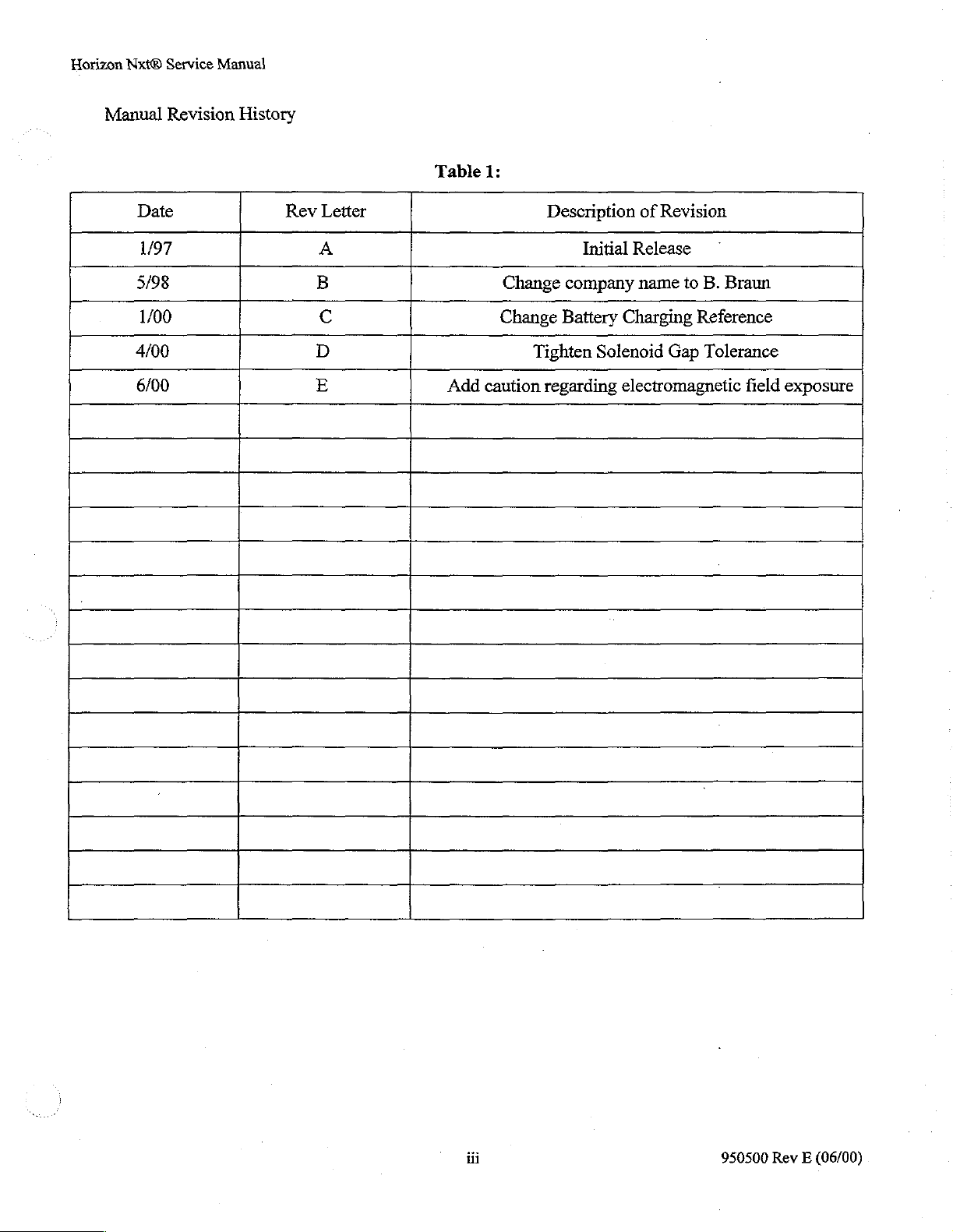
Manual
Date
1/97
5/98
1/00
4/00
6/00
Revision
History
Rev
Letter
A
B
C
D
E
Table
Add
1:
Description
Change
Change
Tighten
caution
regarding
Initial
company
Battery
Solenoid
of
Revision
Release
name
to
B.
Braun
Charging
electromagnetic
Reference
Gap
Tolerance
field
exposure
iii
950500
Rev E (06/00)
Page 6

Page 7
Horizon
Nxt®
Service
‘CONTENTS
Manual
CHAPTER
CHAPTER
CHAPTER
1.0
2.0
3.0
INTRODUCTION
¡NINAS
1.2
WARRANTY
1.3
INTENDED
AAA
....
USE...
DESCRIPTION
2.1
VISUAL
2.2
SPECIFICATIONS
RECOMMENDED
3.1
RECEIVING
3.1.1
3.1.2
3.1.3
3.1.4
3.1.5
3.2
CHECK-INPROCEDURE.......................
INDICATORS
ii
RECEIVING
NOTICES
Damaged
Goods
Late
Expedited
Receiving
Goods
Received
Shipments.........
Shipments
Inspection
AND
CONTROLS
PROCEDURE
ooo
eee.
in
Error................
in
eee
ner
eee
eee
iii
one
eee
nee
me
1-1
„12
sknrns
1-2
2-1
2-5
3-1
3-1
3-1
CHAPTER
4.0
3.3
MECHANICAL
3.3.1
3.3.2
3.3.3
3.3.4
3.4
MAIN
3.5
DEFAULT
3.6
SIMULATED
3.6.1
3.7
VOLUME
3.7.1
3.8
ELECTRICAL
3.8.1
THEORY
4.1
GENERAL
INSPECTION
Door
Alignment
Inspection...
PoleClamplnspection............................
Switch
Gasket
BATTERY
Test
Test
Test
Inspection
and
SOFTWARE
USE
Procedure:
DELIVERY
Procedure:
SAFETY
Procedure:
OF
OPERATION,
DESIGN
Hardware
CHECK
SETTINGS
AND
Simulated
ACCURACY
Volumetric….….......................
CHECK
Electrical
FEATURES
sens
Inspection...........
AND
CHARGING
irene
PERFORMANCE
Use
CHECK.....................
iii
GENERAL
een
sr.
iii
.........................
eee
DESCRIPTION
3-3
3-3
3-3
3-3
„3-3
3-3
3-3
3-4
3-4
4.1.1
Patient
:
Safety...
iv
ドー
トー
トー
に
950500
Rev E (06/00)
Page 8
Horizon
Nxt®
Service
Manual
CHAPTER
5.0
4.1.2
4.1.3
4.2
FUNCTIONAL
4.2.1
4.2.2
4.2.3
4.2.4
4.2.5
THEORY
Si
POWERSUPPLYBOARDASSY.........................................
5.1.1
3.1.2 5 VoltSuppliy.................
5.2
LEDDISPLAYBOARDASSY.............................
5.2.1
(5.2.2
5.2.3
Ease
of
Operation
Upgradabjlity
.es
DESCRIPTION
Case
Power
Main
Half
Door/Bezel
Main
OF
16
Volt
Door
LED
Key
Panel
Bottom
Supply
Battery
Board...
OPERATION,
Processor
Displays
............
uen,
Supply
Interface
and
Repair
rennes
Mechanism.
DETAILED
Assy.
A
DESCRIPTIONS
ーー
emen
ue
aa
a
amma
..
.
5-1
.
5-2
・
5-3
5.2.4
5.2.5
5.2.6
5.3
PRESSURE
5.3.1
5.3.2
5.4
MECHANISM
5.5
MANBOARDASSY......................
5.5.1
5.5.2
5.5.3
5.5.4
5.5.5
5.5.6
A
5.5.8
5.5.9
LCD
LCD
LCD
Contrast
Backight
Module
Voltage....
Sopply
Assÿ..…..
TRANSDUCER
Pressure
Offset,
Transducer
Gain,
and
INTERFACE
Management
Door
Interface
LCD
Interface
IR
Link...
Pump
Processor
Interprocessor
Processor...
Bus
emmek
usines
Communications
CA
Transfer
Temperature
Valve
Controller
Solenoid
ner
...
Circuits...
Output
Circuits...
BOARD
...
Driver
eee
ASSY
Bus...
000”
eee
ns
.
ii
ecran
ii
.
.
λος
う
.5.10
πω
5.5.12
External
Power
Sensor
μμ
Control
Interface
μῥὕϱϱϱϱϱ.
Circuits
v
rire
nie
950500
Rev
(06/00)
E
Page 9
Horizon
Nxt®
Service
Manual
CHAPTER
6.0
5.6
5.7
、
CLEANING
6.1
5.5.13
5.5.14
5.5.15
5.5.16
5.5.17
5.3.18
5.5.19
AIR-IN-LINE
SYSTEM
5.7.1
5.7.2
5.7.3
5.7.4
5.7.5
Voltage
Pressure
Variable
Variable
Time
Audible
References...
Signal
Level
Gain
Of
Day...
Alarms
Overvoltage
BOARD
OPERATION
Power-up........
Hold
State
Run
State
Operation
Keep
Vein
Alarm
State
AND
RECOMMENDATIONS
ieri
Circuits...
Shifter
su
Amplifier...................
rennes
зеленеет
Detection
ASSY.
Circuit...
..........
rien
Operatton
iii
se
Open
State
Operation
....
Operation
DISINFECTING
iii
”
.Ne
ieri
eira
5-16
5-16
5-16
5-16
5-16
emeernne
5-17
5-17
5-18
5-18
e
5-18
5-19
5-20
522
5-22
6-1
CHAPTER
7.0
PREVENTATIVE
7.1
PREVENTATIVE
7.2
EQUIPMENT
7.2.1
Hand
7.2.2
Test
7.23
7.2.4
73
PROCEDURES
7.3.1
7.3.2
7.3.3
7.3.4
7.3.5
7.4
PROCEDURES
Consumables...
Spare
Mechanical
Main
Simulated
Volume
Electrical
MAINTENANCE
MAINTENANCE
REQUIRED
Too!s
iii
Equipment
sise
Parts...
NOT
(6
MONTH)
Inspection...
Battery
Use
Delivery
Safety
REQUIRING
(12
MONTH)
inner
and
Materials..............
REOUIRING
Capacity
and
Performance
Accuracy
Check
AND
PROCEDURES
CASE
DISASSEMBLY
(optional)...
Check
.............
ss
CASE
DISASSEMBLY
REPAIR
ire
seo
on
ena e vena
rei
...................
7-1
7-2
7-2
7-2
7-3
eee
vete
nav
73
0
7-3
rici
7-3
7-4
ui
7-5
7-5
75
REPAR...........................
7.5.1
7.6
DISASSEMBLY
7.6.1
Biomed
Case
Halves
Menu
AND
insu
Oti
c.oocococacicnncannnnnioncannncconacnononacoraracnon
REASSEMBLY
vi
enano
7-8
INSTRUCTIONS...........
©
950500
7-10
7-10
Rev E (06/00)
Page 10
Horizon
Nxt®
Service
Manual
CHAPTER
8.0
7.6.2
7.6.3
7.6.4
7.6.5
7.6.6
7.6.7
7.6.8
769
76.10
7.6.11
7.6.12
7.6.13
7.1
CALIBRATION,
7.7.1
7.7.2
PARTS
Pole
Clamp
Management
Main
Board
Мана
ВаЧету...............
PoWer
Cooling
Petal
Cover
HalfDoor/BezelAâssembiy.............................................
sn
and
ere
ereta
SupPPHy
Fan
.ee
and
ins
Pump
Main
Processor
Speaker..
EPROMS
and
Fuses........
아 아
„72
7-14
아아
CosmeticBezel.............................................................
LED
Display/LCD
LCD
PCB...
Door
Lever...
ADJUSTMENTS,
Elecironic............................
Mechanical
LISTS,
SCHEMATICS,
Controller
eee
AND
AND
PCBS
SPECIFIC
DRAWINGS
ee
TESTS
7-23
ei
7-24
ーー
7-25
......7-26
CHAPTER
CHAPTER
APPENDIX
APPENDIX
APPENDIX
9.0
10.0
A:
B:
C:
NINA
8.2
ELECTRICAL
SERVICE
9.1
CONTACT
AND
MONITOR
10.1
DESCRTPTTON
10.2
INSTALLATION
10.2.1
10.22
10.2.3
10.3
STORAGE
10.4
TROUBLESHOOTING..................
System
DockingSetUp........................
Disconnecting
Abbreviations
Troubleshooting
Operation
Log.................
COMPONENTS
PERFORMANCE
INFORMATION..
DOCKING
eee
eee
Requirements.
Monitor
AND
MAINTENANCE
and
Symbols.…..................................
Guide
AND
ee
Docking
SCHEMATICS
een
.ee
rss
8-1
..................
mmeeesimsemenen
8-1
9-1
..
10-2
10-2
ee
ooo
eee
anne
10-3
A-1
vii
950500
Rev E (06/00)
Page 11
Horizon
1.0
Nxt®
INTRODUCTION
11
DISCLAIMER
Due
uct
be
sional
current
edgeable
ical
not
specifically
Service
to
Manual
the
criticality
performed
who
has
Service
in
the
devices,
testing,
of
product
only
by
attended
the
Manual.
areas
of
microprocessor
static
been
identified
performance,
an
authorized
B.
Braun
Repairs
should
control
in
B.
service
controlled
and
soldering
this
Service
Braun
not
be
B.
Braun
recommends
Service
training
course.
attempted
electronics,
techniques.
Manual.
Center
Repairs
by
other
digital
Repairs
that
all
required
or a qualified
should
than
qualified
and
should
biomedical
not
analog
not
be
service
repair
be
attempted
personnel
circuitry,
that
electromechan-
attempted
on
this
profes-
without
are
knowl-
which
prod-
a
have
WARNING:
CAUTION:
CAUTION:
CAUTION:
Ifthe
product
replaced
Section
3.7
the
an
exception
warranties
Rework
passed
ten
so
will
individual
ties
sentative.
complete
Do
manently
ment
or
repaired,
3.6
of
and
3.8
Horizon
and
of
multi-layer
an
accredited
consent
has
void
component
unless
express
B.
circuit
not
use
the
damage
in
question.
is
partially
the
this
manual
prior
to
use
Nxt
for
pump
set
must
sterility
liabilities.
boards should
course
been
obtained
all
warranties.
replacement
written
Braun
recommends
function
pump
the
in
pump.
or
completely
unit
must
and
the
for
patient
be
performed
only.
in
soldering
from
consent
to
factory
the
presence
For
disassembled,
undergo
appropriate
care.
and
pass
calibrations
All
final
with a set
Failure
has
board
to
not
be
techniques
an
authorized
is
not
recommended
been
replacement
do
so
attempted
obtained
specifications.
of
strong
further
information
electromagnetic
or a component
all
performance
and
performance
that
is
acceptable
may
cause
bodily
unless
for
this
B.
Braun
from
as
consult
personnel
type
Representative.
and
will
an
authorized
it
may
the
or
assembly
checks
or
tests
outlined
testing
and
for
harm
calibration
patient
and
have
of
board
and
void
any
and
B.
not
be
possible
fields.
The
field
manufacturer
has
outlined
in
Sections
use
will
void
attended
express
Failure
Braun
all
warran-
to
test
to
Repre-
may
of
the
equip-
been
in
of
with
all
and
writ-
do
per-
By
performing
agree
that
B.
Braun
all
damages,
out of
You
or
also
auential
this
device
as
well
results
B.
Braun
or
responsibility
institution’s
liabilities,
resulting
understand
loss,
damage,
since
as
other
obtained
from
neither
authorized
any
repairs
and
its
actions
from
such
that
or
the
guality
factors
relating
its
assumes,
in
connection
or
with
or
without
distributors
or
causes
repairs.
neither
expense
of
repair,
to
B.
Braun
directly
matters
use.
nor
authorizes
with
repair
unauthorized
use
shall
of
action,
nor
or
and
the
beyond
any other
of
repair
of
this
manual
be
indemnified
including
its
distributors
indirectly
knowledge
arising
B.
Braun's
person
this
device.
during
1-1
the
as
reference,
and
held
attorney’s
shall
from
and
experience
control,
to
assume
B.
Braun
warranty
you
harmless
fees,
be
liable
authorized
of
personnel
directly
for
it,
any
accepts
no
period.
hereby
from
and
directly
for
any
incidental
or
unauthorized
affect
financial
other
or
950500
the
acknowledge
against
or
indirectly
or
repair
performing
device
and
additional
obligations
Rev E (06/00)
and
any
and
arising
conse-
of
repairs,
the
liability
for
any
Page 12
Horizon
1.2
Nxt®
Service
The
information
WARRANTY
B.
Braun
fusion
ship
for a period
to
meet
B.
Braun’s
modification,
In
this
be
returned
B.
Braun
lieu of
operation
fitness,
beyond
shall
not
from
the
rizes
any
this
device.
has
been:
hereby
Pump.
these
option,
case,
to
will
and
excludes
of
since
B.
Braun’s
be
liable
use
other
Manual
When
standards
or
an
estimate
B.
be
law
handling,
of
this
person
This
contained
warrants
in
that
properly
of
one
year
after
within
will
be
replaced
abnormal
Braun
at
the
or
otherwise
control, directly
for
device
warranty
conditions
will
be
properly
purchaser’s
all
other
storage,
any
incidental
other
to
assume
will
this
manual
reasonable
used
and
maintained,
the
date
this
one
year
without
of
operation,
submitted
packaged,
risk.
The
warranties
including,
and
than
for
not
not
but
cleaning
affect
or
consequential
replacement
it,
another
apply
is
current
care
has
of
shipment.
period
charge.
before
work
postage
foregoing
expressly
not
limited
of
these
these
devices
or
to
any
Horizon
as
of
the
date
been
used
in
it
shall
be
free
Any
Horizon
will
be
repaired
Ifthe
defect
repairs
will
is
started,
prepaid.
Loss
be
express warranty,
set
forth
herein,
to,
any
implied
devices,
and
loss,
of
all
or
additional
as
the
damage
part
of
liability
Nxt
Infusion
of
issue.
the
manufacture
from
defects
Nxt
after
has
been
billed
at
if
requested.
or
damage
whether
warranties
well
as
results
obtained
or
expense,
it.
B.
Braun
or
responsibility
Pump
of
each
in
material
Infusion
Pump
examination
caused
B.Braun’s
as
factors
by
misuse,
then
The
defective
in
return
conditioned
expressed
of
merchantability
relating
from
their
directly
neither
or
component
or
assumes,
Horizon
and
that
by
B.Braun , or,
Nxt
workman-
is
found
unauthorized
current charges.
device should
shipment
and
to
indirectly
in
connection
to
limited,
or
implied
other
matters
use.
B.
nor
thereof
Braun
arising
autho-
which
In-
not
at
is
in
by
or
with
This
warranty
by,
any
1.3
INTENDED
This
manual
and
repair
medical
B.
Braun
institution
tomer
maintains
B.
Braun.
NOTE:
¢
Repaired
*
Altered
*
Subjected
*
Used
Manual
extends
other
person.
USE
is
of
the
service
prior
upon
Service
the
(see
right
by
anyone
in
any
way
to
misuse,
in
any
manner
and/or
intended
referenced
Service
only
to
to
be
equipment.
professional.
to
servicing
the
expiration
Chapter
to
This
manual
vided
Pump.
other
unauthorized
ability
the
9)
withhold
contains
solely
than
None
for
for
of
use
for
infringement
other
than
that,
in
B.
negligent
not
according
Manual.
the
first
purchaser
used
by a gualified
Although
Horizon
of
the
standard
for
additional
the
purchase
information
technical
the
information
the
maintenance
of
the
information
authorized
Braun’s
handling,
to
the
or
Repair
it
Nxt
is
not
Pump,
of
mandatory
Horizon
information
of
parts
personnel
contained
and
of
trade
secrets,
B.
Braun
judgement,
or
accident;
affects
instructions
lessee
biomedical
the
and
device
service
should
that
it
is
recommended,
Nxt
Infusion
on
the
until a service
]
and
data
proprietary
in
maintaining
herein
servicing
of
contained
copyright,
trained
technician
its
furnished
does
not
extend
professional
only
each
service
and
Pump
training
classes
professional
to
and
servicing
may
be
the
pumps
herein
may
and
patents.
or
stability
be
or
by
B.
Braun
to,
and
performed
professional
will
be
warranty.
and
has
B.
Braun
the
duplicated
or
their
subject
the
repair
reliability;
.
for
facility;
in
the
Operation
may
not
be
the
troubleshooting
by a qualified
be
certified
made
available
Please
fee
structure.
been
This
Horizon
or
used
component
user
contact
certified
information
Nxt
in
any
parts.
to
substantial
]
enforced
bio-
by
to
your
Cus-
B.
Braun
by
is
pro-
Infusion
manner
Any
li-
1-2 950500
Rev E (06/00)
Page 13

Horizon
Nxt®
Service
This
Service
Operation
Operation
Manual
Manual
Manual
Manual
is
organized
is
included
for
the
into
at
the
intended
use
end
ten
chapters
of
this
of
this
as
outlined
manual
infusion
for
pump.
in
easy
reference.
the
Table
Please
of
Contents. A Horizon
refer
to
Chapter 1 of
Nxt
the
1-3
950500
Rev E (06/00)
Page 14

Horizon
2.0
ПЕ
Nxt®
Service
DESCRIPTION
2.1
VISUAL
Manual
INDICATORS
AND
CONTROLS
—S
TE
PIGGYBACK
Figure
1.
PRIMARY
2.
Primary
3.
POWER
4.
AC
5.
Battery
6.
HOLD
POWER
PAPA
2-1:
Rate
Key
Use
Indicator
Use
Indicator
[ac + ar
RATE
ML/HR
VOLUME
180]
Front
View
Indicator
Display
Indicator
Key
ROLES
TO
BE
DELIVERED
RN
2500
AE
DV
PIGGYBACK
7.
RUN
8.
ALARM
9.
Primary
10.
PRIMARY
11.
PIGGYBACK
12.
Door
AA
Z
=”
Indicator
Indicator
Volume
RUN
Lever
つぐ
Display
Key
RUN
の
Key
τς
em
2-1
950500
Rev E (06/00)
Page 15
Horizon
Nxt®
Service
Manual
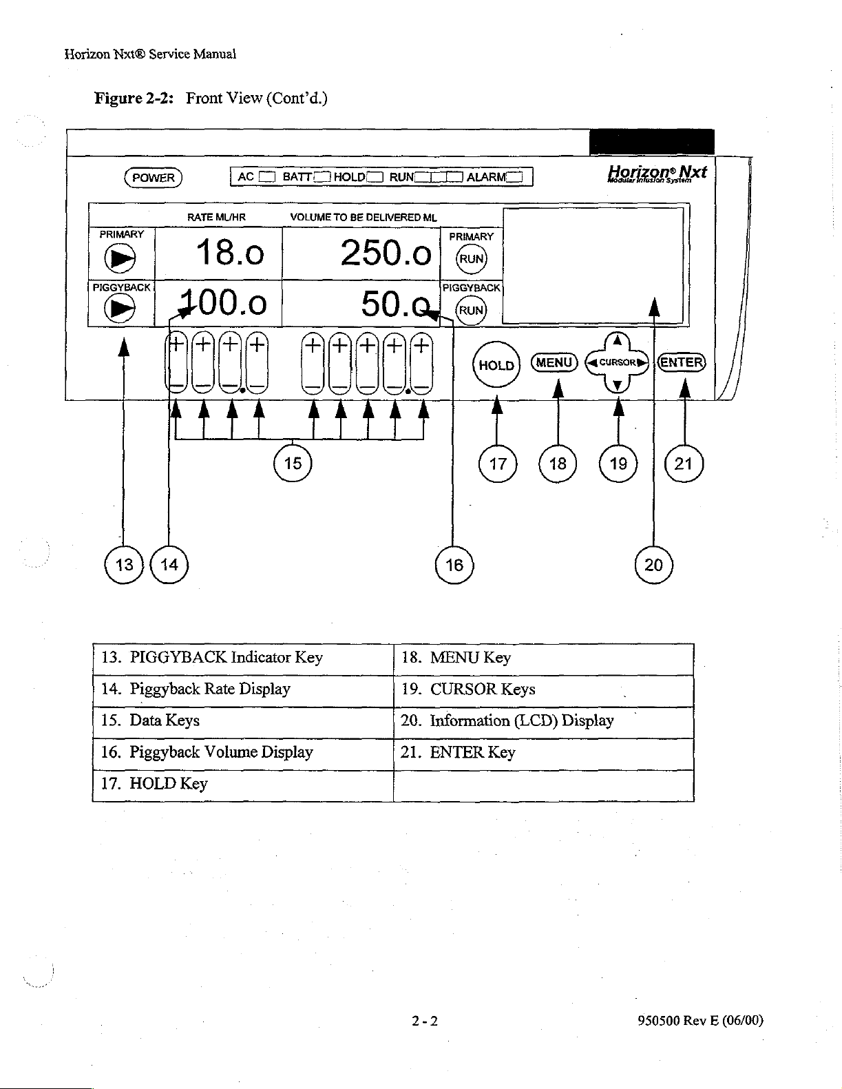
Figure
PRIMARY
Φ
"=="
2-2:
Front
View
(Cont'd.)
POWER
RATE
|
LAC
CI
MUHR
18.0
BATTET
VOLUME
400.0
1000
Minis
€
HOLD]
TO
BE
DELIVERED
oe
RUNC
ALARM]
ML
PRIMARY
|
==
cet
dde
Horizons
Nxt
13.
PIGGYBACK
14.
Piggyback
15.
Data
16.
Piggyback
17.
HOLD
Rate
Keys
Volume
Key
Indicator
Display
Key
Display
18.
MENU
19.
CURSOR
20.
Information
21.
ENTER
Key
Key
Keys
(LCD)
Display
2-2
950500
Rev E (06/00)
Page 16
Horizon
Nxt®
Service
Manual
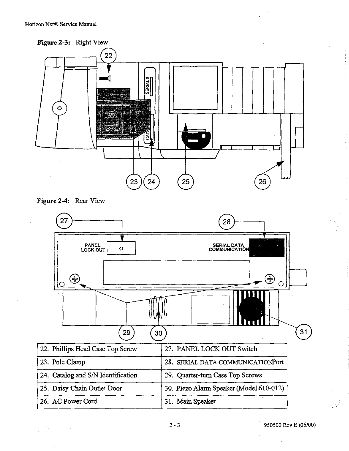
Figure
1
Figure
2-3:
2-4:
Right
Rear
View
View
ma
#
SERIAL
===
CAT
COMO
X
У
©
(2
„©
22.
Phillips
23.
Pole
24.
Catalog
25.
Daisy
26.
AC
Power
一
LOCK
+.
Head
Clamp
and
Chain
一
一
OUT
PANEL
Case
Top
S/N
Identification
Outlet
Cord
Door
o
Screw
SERIAL
COMMUNICATION
DATA
r
Bo
|
|
|
27.
PANEL
28.
SERIAL
29.
Quarter-turn Case
30.
Piezo
31.
Main
Alarm
Speaker
LOCK
DATA
OUT
Switch
COMMUNICATIONPort
Top
Screws
Speaker
(Model
610-012)
2-3
950500
Rev E (06/00)
Page 17

Horizon
Nxt®
Service
Manual
Figure
2 3
2-5:
Front
View,
4
Door
Open
1.
Cassette
2.
Inlet
3.
Refill
4.
Transfer
5.
Petal
6.
Restriction/Outlet
Alignment
Valve
Piston
Valve
Module
Pins
Cover
Valve
7.
Air-In-Line
8.
Anti-Freeflow
9.
Pressure
10.
Tube
Pusher
11.
Spring
2-4
10
Detector
Socket
Transducer
(Free
Flow
Prevention)
950500
Rev E (06/00)
Page 18
Horizon
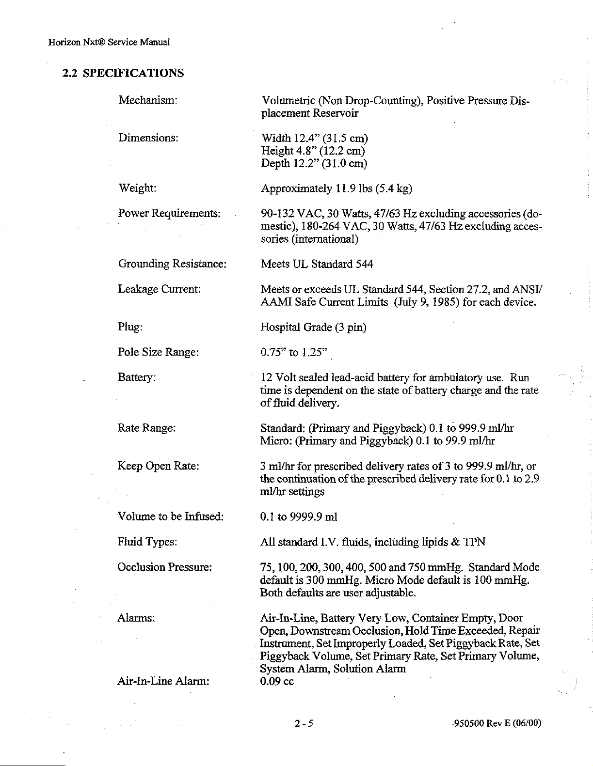
2.2
Nxt®
Service
Manual
SPECIFICATIONS
Mechanism:
Dimensions:
Weight:
Power
Grounding
Leakage
Plug:
Pole
Battery:
Requirements:
Resistance:
Current:
Size
Range:
Volumetric
placement
Width
Height
Depth
Approximately
90-132
mestic),
sories
Meets
Meets
AAMI
Hospital
0.75”
to
12
Volt
time
is
of
fluid
(Non
Reservoir
12.4"
(31.5
4.8"
(12.2
12.2”
(31.0
VAC,
180-264
(international)
UL
Standard
or
exceeds
Safe
Current
Grade
1.25”
sealed
dependent
delivery.
Drop-Counting),
cm)
cm)
cm)
11.9
lbs
(5.4
30
Watts,
VAC,
UL
(3
lead-acid
544
Standard
Limits
pin)
on
the
47/63
30
Watts,
battery
state
kg)
Hz
544,
(July
for
of
battery
Positive
excluding
47/63
Hz
Section
9,
1985)
ambulatory
for
excluding
charge
Pressure
accessories
27.2,
each
and
use.
and
Dis-
acces-
ANSI/
device.
Run
the
(do-
rate
Rate
Range:
Keep
Open
Volume
Fluid
Occlusion
Alarms:
Air-In-Line
to
be
Types:
Pressure:
Rate:
Infused:
Alarm:
Standard:
Micro:
3
ml/hr
the
continuation
ml/br
0.1
to
All
standard
75,
100,
default
Both
Air-In-Line,
Open,
Instrument,
Piggyback
System
0.09
(Primary
(Primary
for
prescribed
settings
9999.9
ml
IV.
200,
300,
is
300
mmHg.
defaults
are
Battery
Downstream
Set
Volume,
Alarm,
cc
and
Piggyback)
and
Piggyback)
delivery
of
the
prescribed
fluids,
400,
including
500
and
Micro
user
adjustable.
Very
Low,
Occlusion,
Improperly
Set
Solution
Loaded,
Primary
Alarm
0.1
0.1
rates
of 3 to
delivery
lipids € TPN
750
mmHg.
Mode
default
Container
Hold
Time
Set
Rate,
to
999.9
to
99.9
ml/hr
999.9
rate
-
Standard
is
Empty,
Exceeded,
Piggyback
Set
Primary
ml/hr
for
100
ml/hr,
0.1
to
or
2.9
Mode
mmHg.
Door
Repair
Rate,
Set
Volume,
2-5
«950500
Rev E (06/00)
Page 19

Horizon
Nxt®
Service
Hold
Manual
Time
Exceeded:
Activated
tivated
if
the
after
three
door
minutes
of
the
pump
without
is
open)
user
interaction
(deac-
Memory:
Permanent
the
Data
Retention
the
Biomed
data
retention
Defaults
Options.
after
the
have
pump
been
is
turned
otherwise
off,
unless
selected
in
2-6
950500
Rev E (06/00)
Page 20

Horizon
3.0
Nxt®
RECOMMENDED
3.1
RECEIVING
New
tion
numbers,
of
box
Service
Device
will
be
or
failure.
Manual
RECEIVING
NOTICES
Notice:
replaced
preventative
Any
only
maintenance
new
if
the
device
device
tags.
PROCEDURE
that
does
not
is
not altered,
Ifa
device
meet
i.e.
is
factory
hospital
used
specifications
identification
on a patient,
during
markings,
it
will
not
be
in-coming
asset
inspec-
control
considered
an
out
WARNING:
3.1.1
Damaged
Upon
should
age
company.
mediately,
happy
and
forwarded
request
tation
3.1.2
Goods
_
Ifthe
replaced
Section
3.7
and
Horizon
tion
ties.
Goods
receipt,
not
be
or
loss
noted
If
and
to
issue a credit
the
carrier’s
to
must
be
company
Received
product
for
count
is
or
repaired,
3.6
of
this
3.8
prior
Nxt
must
set
sterility
and
accepted.
on
the
damage
request
is
that
for
freight
the
Carrollton,
accompanied
has
properly
in
Error
partially
manual
to
inspect
or
the
unit
and
use
for
be
performed
only.
Failure
your
patient
Identify any
customer’s
discovered
inspection
the
loss
bill
indicating
Texas
copy
after
or
damage,
office
by a delivery
noted
such
completely
must
the
disassembled,
undergo
appropriate
care.
with a set
to
do
so
freight
items
be
before
that
are
of
the
delivery
receipt
made
of
and
and
the
item and
(see
Chapter
receipt
damage
and
pass
calibrations
All
final
performance
that
is
acceptable
may
cause
the
carrier
damaged
document
shipment,
an
inspection
file a claim
quantity
9),
and
or
an
inspection
or
loss.
or a component
all
performance
and/or
testing
for
bodily
or lost,
notify
with
damaged
received
harm
departs.
report
the
Damaged
and
have
by
an
the
transportation
rendered.
carrier,
or
within
agent
report
or
assembly
checks
tests
outlined
and
patient
and
use
will
the
of
providing
not
received
ten
upon
which
has
been
outlined
in
Sections
calibration
with
void
of
an
excep-
all
warran-
merchandise
extent
the
of
the
dam-
transportation
company
B.
Braun
days.
will
your
reque
are
promptly
The
the
transpor-
claim
in
the
im-
be
Items
notified
be
Credit
ordered
returned
will
1.
Proper authorization
2.
Products
3.
Products
4.
Merchandise
Certain
1.
2.
products
Products
Products
(see
Chapter
freight
be
or
shipped
issued
are
in
are
current
has
are
which
whose
in
9),
and
prepaid
for
by
all
has
the
original
inventory
been
shipped
not
eligible
have
been
labels
or
error
may
the
products
the
customer.
returns
been
for
obtained
undamaged
items.
and
for
used.
seals
have
be
returned
are
goods
billed
return
for
been
3-1
to
returned
received
(see
Chapier
cases,
suitable
to
the
credit.
tampered
the
warehouse
within
in
error
9).
for
customer
These
with
are:
or
provided
14
days.
Items
provided:
immediate
by
B.
Braun.
removed.
Customer
ordered
resale.
950500
Service
in
error
is
must
Rev E (06/00)
Page 21

Horizon
Nxt®
Service
Manual
3.1.3
3.1.4
3.1.5
Except
Late
B.
yond
acts
strike,
Expedited
When
by
in
the
Shipments
Braun
shall
its
or
of
government,
labor
expedited
the
customer,
Receiving
Each
Horizon
ment.
therefore,
your
There
the
(customer)
case
of a B.
be
excused
its
suppliers’
acts
trouble,
Shipments
sabotage
transportation,
an
additional
Inspection
Nxt
Infusion
is,
however,
following
policy,
Braun
from
or
of
error,
any
delay
subcontractors’
purchase
or
priorities
delay
specialized
charge
Pump
the
possibility
inspection
refer
to
the
to
is
factory
is
recommended.
section
items
must
in,
or
control,
or
in
obtaining
services,
cover
the
inspected
of
in-transit
in
this
be
returned
impossibility
freight
of
including,
allocations,
labor,
or
alternate
premium
and
damage
If
functional
chapter
raw
materials,
expense
tested
which
titled
prepaid
performance
but
not
limited
material
shortages,
equipment,
transportation
will
be
added
prior
to
its
final
may
or
may
testing
“CHECK-IN
is
required
PROCEDURE.”
by
the
customer.
due
to
any
cause
to:
acts
of
God,
fire,
flood,
or
transportation.
modes
packaging
to
not
upon
are
specified
the
invoice.
and
be
obvious;
receipt
be-
war,
ship-
by
3.2
CHECK-IN
Prior
manual.
(RMA#).
Before
1.
age.
opening
If
damage
until a representative
for
shipping
to
the
company
.
Remove
Www
Carefully
ping
damage.
.
Make
A
aligned
un
.
Make
.
Check
.
Inspect
.
Make
01d
erwise
manufacturer
sure
sure
sure
damage
is
responsible
the
pump
inspect
the
with
the
there
the
Pole
the
power
the
damaged.
PROCEDURE
to
use,
it
is
recommended
If
the
pump
See
Chapter 9 for
fails
the
shipping
is
present,
of
after
unless
from
the
pump
door
of
the
bezel.
are
no
visible
Clamp
petal
for
cord
for
module
that
to
operate,
information
container,
notify
the
the
the
shipping
shipping
specifically
for
the
repair.
the
shipping
for
dents,
pump
opens
dents,
ease
of
operation.
nicks
or
cover,
the
contact
valve
pump
B.
on
contacting
inspect
freight
carrier
company
container
authorized
carton.
scratches,
and
closes
tears
or
scratches
cuts,
and
the
tips
be
checked-in
Braun
for a Returned
the
it
carefully
immediately,
is
present.
is
opened).
to
do
missing
easily,
plug
for
and
pressure
according
company.
to
assure
(It
is
Do
so
by
the
parts,
or
without
on
the
pump
bent
or
transducer
to
Sections
Materials
the
absence
and
wait
to
difficult
not
to
return
company,
any
other
obvious
binding,
and
membrane
insecure
prongs.
cover
3.3
Authorization
of
obvious
open
the
place
responsibility
damaged
whether
that
panel.
are
not
through
container
equipment
or
not
signs
of
it
is
properly
torn
or
3.8
of
Number
dam-
the
ship-
oth-
this
Each
may
used
pump
have
caused
by
qualified
has
been inspected
some
misalignment.
service
and
personnel
tested
prior
Therefore,
in
the
initial
to
shipment;
the
and
3-2
however,
procedures
routine
outlined
checks
in-transit
in
this
of
the
Horizon
handling
chapter
Nxt
950500
are
Infusion
or
repair
intended
Pump.
Rev E (06/00)
work
to
be
Page 22

Horizon
3.3
Nxt®
Service
Manual
MECHANICAL
INSPECTION
3.3.1
3.3.2
See
Table
3.3.3
See
Table
3.3.4
Door
Alignment
1.
Make
aligned
2.
The
Pole
Clamp
3-2, # 1.
Switch
3-2, # 2.
Gasket
1.
All
2.
Petal
3.
The
marks.
All
No
Tube
No
Inspect
none
sure
the
with
the
gap
on
each
Inspection
Inspection
and
Hardware
gaskets
module
cover
screws
cracks
pusher
cracks
on
are
in
the
and
cover
the
are
is
the
power
Inspection
door
of
the
bezel.
side
and
The
Inspection
seals
are
securely
and
valve
pressure
tight
and
secure.
present
intact
case
cord
in
the
and
securely
or
handle
for
pump
along
opens
door
the
latch
top
attached.
tips
are
transducer
bezel
or
shall
inner
mounted.
exist.
nicks
or
cuts.
and
closes
allows
of
the
in
place
not
door
Inspect
easily,
the
door
door
and
have
face.
the
without
to
close
is
symmetrical.
in
good
condition.
any
rips,
tears,
plug
for
bent
binding,
and
completely.
punctures
or
insecure
that
it
is
properly
or
indentation
prongs.
3.4
MAIN
All
pump
the
Allow
the
whenever
12
3.5
DEFAULT
A
by
BATTERY
rechargeable
is
no
exception.
battery
battery
be
at
least
in a fully
fully
24
possible.
Horizon®
and/or
SOFTWARE
1.
Set
all
pumps.
2.
Verify
list
of
all
the
contacting
Technical
CHECK
batteries
Therefore,
charged
hours
to
charged
When
Horizon
defaults
Refer
to
that
the
options
in
Support
AND
CHARGING
automatically
it
is
suggested
by
connecting
fully
charge
the
condition,
charging
Nxts
multiple
may
SETTINGS
according
the
pump’s
the
PC
Docking
calendar
Menu
to
your
System,
Services
discharge
that
the
power
battery
the
pump
devices
be
Daisy
Chained
individual
Operation
and
clock
and
the
at
(800)
3-3
when
not
in
before
cord
from a fully
should
attempting
of
the
be
plugged
in a storage
together
institution’s
Manual,
are
set
appropriately.
submenus
627-7867.
use.
The
rechargeable
to
pump
to a hospital
discharged
into a hospital
facility,
for
outlet
needs.
Part
No.
950441,
in
which
they
use
the
pump
grade
condition.
grade
not
in
the
conservation
Use
PC
Docking
for
can
be
battery
In
used
in
for
the
first
electrical
order
outlet.
to
maintain
electrical
vicinity
instructions.
placed,
950500
of
patients,
purposes.
to
program
is
available
Rev E (06/00)
this
time,
outlet
the
Page 23

Horizon
3.6
Nxt®
Service
SIMULATED
Manual
USE
AND
PERFORMANCE
CHECK
Action
.
Unlock
lever
turn.
down
holding
the
case.
supported
press
ver
the
Press
Equipment
1.
Horizon®
2.
Container
3.
Needle
4.
LV.
5.
AC
3.6.1
Table
pole
1/4
pump
Test
3-2:
the
Pole
clockwise
Attach
on
Release
down
the
the
the
unlocked
the
lever
is
seated
the
by
the
on
turn
counterclockwise
to
lock
Power
Required:
Pump
with
and
pole
or
power
Procedure:
Simulated
Clamp
toward
pump
down,
in
Pole
I.V.
the
the
Key
by
the
to
Pole
position
the
V-block
Clamp.
pole,
pump.
Pole
to
turn
source
LV.
Set
suitable
3ml
Syringe
equivalent
Simulated
Use
Initial
rotating
front
an
LV.
Clamp
use one
Rotate
Clamp.
on
the
of
the
pole
lever.
the
pump
of
the
With
the
hand
the
towards
the
pump.
fluid
in
it
Use
Checkout
Pole
Clamp
pump
by
instrument
Pole
the
1/4
pressing
While
such
pump
now
to
lightly
Clamp
back
Observation
1.
that
le-
of
Verify
onto
Note:
The
HOLD
To
Be
LCD
the
Pole
the
pole.
As
the
open
er,
the
pump
mounted
speaker
will
will
LEDs
Delivered
illuminate
Clamp
on
will
mechanism
Pole
Clamp
will
become
the
I.V.
sound a tone.
illuminate.
columns
and
lever
more
pole.
The
The
Rate
will
display
display:
tightens
is
snugged
securely
BATT
and
and
Volume
values,
firmly
tight-
the
and
Total
Occlusion
Note:
Ifno keys
ly
30
seconds,
the
Primary
is
not
active.
3
min.,
“HOLd”
ume
To
Be
and
the
alarm
Load
the
then
close
Infused = 0.0
Limit = 300
have
been
pressed
“HOLd”
or
Piggyback
If
no
keys
will
flash
Delivered
will
sound.
Set
the
Door.
mmHg
for
will
be
channel,
have
been
in
the
column
950500
ml
approximate-
displayed
whichever
pressed
Primary
of
the
Rev E (06/00)
in
Vol-
LED’s
for
Page 24

Horizon
Nxt®
Service
Manual
3.
4.
5.
Table
Individually
each
DATA
GYBACK
the
Piggyback
values
Enter a Primary
10.
Press
to
Press
the
3-2:
Simulated
press
Key
to
INDICATOR
Rate
zero.
rate
the
PRIMARY
MENU
Key,
and
hold
verify
and
of
900
then
Use
Initial
the + and - portion
operation.
Key
and
Volume
and a Primary
RUN
Key.
the
repeat.
To
HOLD
Checkout
Press
Be
Delivered
Key.
of
the
PIG-
Return
volume
of
3.
Key
clicks
dible
tone
Rate
and
Delivered
decremented
attempt
0.0
ml.
Note:
4.
The
audible
proximately
LED
will
ume
To
HELP”.
5.
The
LCD
are
heard
will
sound
the
thousands
are
advanced
past
0.
is
made
to
set
Whichever
INDICATOR
TOR,
the
respective
brighter,
dimmer.
illuminate.
Be
Delivered
The
Then
Check
will
while
alarm
will
once
every
LCD
will
CLOSE
open
Placement
Secure
(picture)...
display:
as
the
as
the
column
past 9 or
This
same
the
rate
key
is
or
PIGGYBACK
the
begin
three
The
LEDs
column
display:
ROLLER
door.
Flow
Сатр-у
LEDs
depressed,
sequence.
hundreds
of
the
Volume
if
any
tone
will
or
volume
display
other
to
seconds.
will
will
display
sound
in
the
flash
CLAMP
of
column
PRIMARY
and
The
Primary
An
a.
of
the
To
Be
column
sound
less
INDICA-
illuminate
becomes
“SEE
is
if
than
repeat
ALARM
ap-
Vol-
an
6.
Press
the
MENU
CURSOR
ed.
Press
CURSOR
lighted.
7.
Cursor
Key
the
Key
Press
left
and
Key
until
ENTER
until
the
ENTER
right.
followed
“Alternate
“Set
Key.
LCD
Key.
by
the
Menu”
Press
the
Contrast”
down
arrow
is
highlight-
down
arrow
is
high-
Load
and
then
Total
Occlusion
Flow
6.
The
LCD
will
Adjust
this
Then
7.
The
contrast
high
present
cursor
message
press Enter
changes
again.
and
The
not
Infused = 0.0
Limit = 300
Clamp
display:
< —
is
clear.
from
backlight
erratic
the
Set
close
the
Position
EXIT
until
key.
high
to
intensity
or
flickering.
Door.
ml
mmHg
HELP
low
and
should
950500
back
to
be
Rev E (06/00)
Page 25

Horizon
Nxt®
Service
Manual
©.
Press
9.
Open
10.
Spike
the
the
instruction
11.Press
Piggyback
¿2.Close
press
Table
the
ENTER
the
door.
the
set
with
set
before
cassette
into
the
PIGGYBACK
the
clamp
the
PRIMARY
3-2:
fluid
container
fluid.
closing
the
label
rate
Simulated
Key.
Make
pump
inside
and
volume
downstream
Use
with
sure
the
roller
mechanism
the
Indicator
RUN
Initial
the
all
air
clamp.
door.
of
0.0.
from
Key.
Checkout
I.V.
set,
and
is
removed
Load
according
Close
Key
and
the
cassette
the
prime
from
the
to
the
door.
enter
and
a
8.
The
LCD
9.The
only
display
onds,
after
play
“HOLd”.
Time
Exceeded
10.
The
Rate
display
ing
11.
The
PIGGYBACK
PRIMARY
12.
The
with a complete
should
sage
those
the
door.
LCD
“Total
of
will
display:
and
then
Total
Occlusion
Flow
Clamp
change
which
and
Volume.
Occlusion
will
sound
“OCCL.”
the
Opening
alarm.
Volume
values
The
LCD
Set
Total
Flow
Clamp
drop
LEDs
LEDs
Infused
occlusion
associated
Load
the
Set
close
Infused = 0.0
Limit = 300
PIGGYBACK
To
that
the
Then
Infused = 0.0
Limit = 300
the
will
will
become
=”
value
the
Position
will
occur
the
door
Be
Delivered
were
present
will
illuminate
Rate
&
Press
Position
last
line
of
illuminate.
dim.
should
and
an
with a flashing
Door.
mi
mmHg
HELP
after
several
LEDs
disables
columns
prior
and
RUN.
mí
mmHg
HELP
text.
The
The
stop
increasing
audible
LED
sec-
will
dis-
the
Hold
will
to
open-
display:
row
of
row
of
alarm
mes-
13.
Press
the
HOLD
clamp.
and
Clamp
press
the
PRIMARY
Key
the
and
tubing
open
the
upstream
RUN
Key.
downstream
of
the
pump
Note:
Note:
13.
Note:
The
amount
how
far
downstream
sion
limit
The
Occlusion
crease
fect
exceed
The
“Total
with a complete
should
sage
The
how
limit
of
Infused
sound
of
“SOLU.”
amount
far
setting
to
400
tubing
399.9
upstream
of
time
setting
associated
as
Limit
mmHg
flow
resistance
ml/hr.
=”
value
occlusion
of
time
the
as
well
will
vary
depending
the
clamp
well
as
will
to
compensate
should
and
with a flashing
will
vary
clamp
as
the
is,
the
the
infusion
automatically
as
infusion
stop
increasing
an
audible
depending
is,
the
occlusion
infusion
950500
Rev E (06/00)
upon
occlu-
rate.
in-
for
the
rates
alarm
LED
upon
rate.
ef-
mes-
Page 26

Horizon
Nxt®
Service
Manual
14.
15.
16.
Table
Press
the
tubing.
the
“Y”
the
pump.
When
Press
the
pump
such
upwards,
the
3-2:
Simulated
HOLD
Inject
site
an
of
Press
air
bubble
that
toward
MENU
the
Key
air
tubing
the
the
distal
the
Key.
Use
and
unclamp
bubble
PRIMARY
reaches
ceiling.
of
on
the
the
(delivery
Initial
the
at
least
upstream
RUN
pump,
end)
Checkout
upstream
0.9
ml
side
Key.
tilt
the
is
pointing
into
of
14.
The
15.
The
the
LEDs
flash
16.
The
tinguish.
LCD
cassette
ized,
The
LEDs
LCD
luminate.
will
will
Occlusion
alarm
air-in-line
in
the
“Air.”
alarm
The
will
chambers
HOLD
begin
display:
will
The
Press
will
display:
LED
to
Time
Left = 0
Total
Volume
Infused = 1.8
sound
detector.
RUN
The
LCD
Air
To
Silence
MENU
Press
silence.
HOLD
will
be
filled
will
extinguish.
illuminate
Limit = 400
as
the
The
LEDs
To
Be
will
In
HOLD.
The
LED
sequentially.
hr 0 min
air
bubble
ALARM
will
extinguish.
Delivered
display:
Line
Alarm
for
help,
ALARM
will
illuminate.
and
ml
mmHg
column
or
LED
pressur-...!
The
RU?
The’
passes
LED
into
will
The
will
will
The
il-
ex-
17.
Open
the
door
and
flush
form
the
Volumetric
3.7.1.
10.0
Enter a Primary
ml.
Press
the
RUN
the
Test
as
Volume
Key.
air
in
the
tubing.
described
to
be
Delivered
in
Section
-
Air
in
downstream
-
Tubing
inserted
Detector.
Per-
of
17.
Press
Atthe
Vein
RUN
end
Open
improperly
in
Air-In-Line
Press
of
infusion,
mode.
HOLD
tubing
or
the
pump
will
go
into
Keep
950500
Rev E (06/00)
Page 27

Horizon
Nxt®
Service
Manual
19.
20.
21.
22.
Table
.
Wait
Open
Press
Press
“Clear
Press
3-2:
until
the
door.
the
HOLD
the
MENU
Total
the
ENTER
Simulated Use
the
infusion
Key.
Key.
Infused.”
Key.
Initial
is
complete.
Press
the
Checkout
ENTER
Key
to
18.
An
tion.
ume
flashing.
19.
The
nate.
umn
20.
The
minate. The
Volume
play;
21.
The
22.
The
alarm sounds,
The
primary
to
be
delivered
The
KVO:
Occlusion
alarm
will
The
LEDs
will
flash
alarm
will
to
be
PRIMARY
Time
Total
Occlusion
LCD
will
The
LCD
will
indicating a KVO
rate
LCD
PRIMARY
Total
sound.
in
“door.”
silence.
Primary
Delivered
Left= 0 hr
Infused=
display:
present
of
10.00
zeroed.
display:
will
be
3.0
ml/hr
will
be
0.0,
each
will
display:
COMPLETE
Infused = 10.0
Limit = 300
The
Alarm
the
Volume
The
rate
will
of
0.o.
COMPLETE
Limit = 300
Total
mi
Is
this
YES
mmHg
LED
to
be
HOLD
display 900 and
The
Отт
10.0
mmHg
Infused
will
be
OK?
NO
state
of
and
the
will
be
mi
will
illumi-
Delivered
LED
will
LCD
will
ml
opera-
vol-
col-
illu-
a
dis-
Press
the
23.
a
POWER
Key
to
turn
the
pump
off.
PRIMARY
Time
Total
Occlusion
23.
The
LED’s
will
display
the
power
lit
while
supply.
3-8
in
“----”
down
the
the
pump
COMPLETE
Left=
Infused = 0.0
Volume
until
cycle.
is
Ohr
Limit = 300
to
be
the
device
The
AC
plugged
into
Omin
ml
mmfig
delivered
has
completed
LED
will
an
AC
950500
Rev E (06/00)
column
remain
power
Page 28

‘Horizon
3.7
Nxt®
Service
VOLUME
Manual
DELIVERY
ACCURACY
Equipment
3.7.1
Table
Volume
10
3-3:
mi
Required:
1.
Distilled
2.
Horizon®
3.
Electronic
4.
Needle
Test
Procedure:
1.
Connect
2.
Attach
3.
Completely
clamp
4.
Insert
pump.
5.
Close
6.
Open
Volumetric
water
Pump
Balance
or
dispenser
the
the
needle
prime
on
the
the
cassette
the
door
all
clamps
Rate
120
in
an
I.V.
or
tip
Volumetric
fluid
delivery
to
the
the
set.
into
and
press
and
Test
Values
mi/br
J.V.
fluid
Set
Precision
with a Luer
set
delivery
set
with
the
pump
the
POWER
enter:
container
Collection
lock
to
the
fluid
end
of
fluid
so
all
according
Key
Pressure
300
mmHg
Vessel
type
connector.
container.
the
I.V.
Set.
the
air
is
to
the
instructions
to
turn
expelled
on
from
the
pump.
Acceptable
9.5 - 10.5
the
set,
inside
the
ml
and
door
Limit
then
of
the
close
the
Horizon
roller
Nxt
Note:
Note:
.
Place
lection
.
Press
eo
ら
When
\
sure
10.
Zero
pump
turn
the
collection
vessel.
the
RUN
Key.
the
pump
the
actual
volume
1ml=1cc=1¢
the
reading
with
additional
the
pump
Tf
using
adaptive
in
section
cause
transitions
tem
first
equipment
LV.
different,
to
other
energy
5.5.7.2
the
motor
dynamics
few
delivery
pumps
typically
vessel
goes
into
delivered
of
on
the
I.V.
an
authorized
accuracy
processing
“Motor
energy
from
the
and
rate)
cycles
will
supply
which
employ
on
the
the
Keep
distilled
balance.
fluid
delivery
B.
test
methods,
Controllers.”
to
rise
Hold
state
momentary
after
you
with
this
all
that
is
balance,
Vein
Open
is
between
water
at
If
the
actual
sets.
Braun
Service
in
used
to
conserve
and
fall
to
the
Run
pauses
the
RUN
written
type
of
required
3-9
zero
the
reading,
mode,
the
acceptable
room
temperature
values
If
the
values
Center.
addition
to
battery
This
dynamic
at
the
beginning
state).
of
the
Key
is
pressed.
instructions
energy
is
that
processing.
you
allow
and
press
the
limits
are
not
remain
the
above,
power
processing
This
results
motor
for
5-10
suspend
HOLD
(70°
within
and
of
an
as
the
listed
infusion
in
the
Key
in
the
F)
the
specifications,
outside
be
sure
the
to
reduce
of
resistance
several
energy
is
Manufacturers
use
of
their
equipment
While
milliliters
volumetric
of
needle
immediately.
over
above
the
Make
table.
test
specifications,
compensate
noise
(each
time
(varies
changed
of
biomedical
for
as
described
to
flow
the
pump
with
the
during
when
testing
analyzers
fluid
to
bleed
950500
Rev E (06/00)
cv.
the
re-
the
will
sys-
the
test
ar,
fro
.
Page 29

Horizon
3.8
Nxt®
Service
ELECTRICAL
Manual
the
system
Contact
procedures
SAFETY
prior
to
starting
the
manufacturer
are
used.
CHECK
the
timer(s)
of
you
or
counter(s). A 3-way
volumetric
analyzer
to
ensure
stopcock
proper
is
software
very
useful
and
testing
here.
Equipment
1.
2.
3.8.1
Note:
Test
에
DWN
Required:
Medical
AC
power
Procedure:
.
Plug
the
.
Make
.
Plug
the
.
Attach
Chain
If
ther
stainless
you
Set the
Set
the
Press
Press
IEC
the
601-1
LIA
equipment
source
Electrical
analyzer
sure
the
pump
the
probe
outlet
using a manual
the
may
into
analyzer
into
to a single
on
the
metal
steel
need
grounding
polarity
the
POWER
Chassis
to
Leakage
specifications
electrical
an
AC
is
functioning
the
AC
outlet
lead
side
of
the
probe
frame
door
selection
latch.
to
scratch
of
the
to
“Normal.”
Key
to
turn
button
as
indicated
safety
analyzer
outlet.
of
the
and
touch
pump
for
Being
and
‘No
your
power
scrape
Ground.”
on
the
and
or
stainless
pump.
make
below.
properly,
according
analyzer.
it
to
the
any
protruding
resistance
supply,
the
checks,
located next
steel,
probe
sure
the
to
aluminum
metal
you
the
door
on
the
latch.
reading
your
institution’s
plate
which
component.
will
need
to
the
Daisy
latch
makes
does
not
exceed
protocol.
supports
to
make
Chain
for a difficult
contact
outlet,
the
UL
the
Daisy
with
or
contact;
544
the
or
the
ei-
Note:
Note:
9.
10.
11.
12.
13.
14.
As
of
the
date
544 and
Chain
chassis
The
IEC
feature
leakage
number
601-1
of
it
Set
the
polarity
Press
the
the
TEC
Press
the
Set
the
Set the
Press
the
or
the
IEC
As
601-1
polarity
grounding
of
to
“Reverse.”
Chassis
Leakage
specifications.
HOLD
Key.
to
Ground
601-1
the
date
with a non-detachable
this
manual
is
on
the
current
pumps
Horizon
was
100
microamps
Nxt
is
cumulative.
interconnected
button
again.
“Off.”
selection
Wire
switch
Resistance
specification.
this
manual
was
power
cord
3-10
written,
the
for
(plugging
Therefore,
at
any
Make
to
“Ground.”
button.
written,
for
Make
the
UL
AC
leakage
patient
one
time
sure
the
vicinity
Horizon
sure
ground
544
and
current
test
all
should
reading
the
reading
wire
resistance
IEC
601-1
specifications
equipment.
or
Horizon
units
connected
not
exceed
does
not
does
the
exceed
not
specification
is
200
for
When
Nxt
using
into
another),
as
one
100
microamp
the
exceed
UL
the
for a device
milliobms.
950500
Rev E (06/00)
both
UL
the
Daisy
the
system.
lim-
544
or
UL
544
Page 30

Page 31

Horizon
Nxt®
Service
15.
16.
17.
Manual
Press
the
POWER
Repeat
Disconnect
steps 8 -
the
Key
14,
pump
on
the
skipping
from
step
the
pump.
11,
with
analyzer.
the
power
Disconnect
off
(optional).
the
analyzer
from
the
AC
power
source.
3-11
950500
Rev E (06/00)
Page 32

Page 33

Horizon
4.0
THEORY
}
4.1
Nxt®
Service
OF
The
following
material
a
few
functional
matics
and
follows a general
significant
description.
and
drawings
symbols
GENERAL
4.1.1
Patient
Manual
OPERATION,
describes
design
used
throughout
DESIGN
Safety
GENERAL
the
basic
theory
to
specific
features.
The
are
cross-referenced
The
detailed
this
descriptions
chapter.
FEATURES
of
operation
format.
next
section,
where
DESCRIPTION
for
The
first
section,
Section
have
been
applicable.
the
Horizon
Section
4.2,
placed
Nxt
4.1,
is
intended
in
Chapter 5 for
Appendix A lists
pump.
gives
to
give
the
The
organization
an
overall
the
reader a top
clarity.
common
of
the
description
of
level
Related
sche-
abbreviations
Patient
of
scribed
Alarm
rections
The
arate
Automatic
safety
the
Horizon
infusions.
and
to
Alarm
events
troubleshooting
correct
Log
to
dose
convenience
The
Horizon
method
mation
Full
formation
Reduced
proach
which
of
operation
displays
visibility
display.
cord
to
power
needs
was a primary
Nxt
pump
incorporates a product
problems
and
Operations
assist
in
troubleshooting
rate
calculations
and
dosing
Nxt’s
assist
of
operating
clutter
cord
to
be
accuracy
ease
of
is
easy
the
user
around
management.
plugged
concern
information
as
use
to
learn. A wide
at
parameters
the
well
as a list
Log
are
are
is
one
each
bed-side
in
use
performed
enhanced
of
step
is
Multiple
into
the
wall.
the
development
design
are
clearly
of
possible
the
Horizon
problems
the
of
and
by
Horizon
by
both
strongest
variety
the
of
infusion
accomplished
results
from
pumps
can
of
the
with
features
visible,
easy
Horizon
that
to
read,
Nxt
pump.
optimize
and
causes.
Nxt’s
real
time
clock
to
record
documenting a specific
Nxt’s
this
feature
factors
contributing
information
unique
and
provided
the
to
series
Dose
Drug
patient
by
process.
with
the
LED
data
displays
using
the
be
Horizon
Daisy
Chained
Nxt’s
together,
The
operation
the
safety
provide
Mode.
specific
up
to
of
events.
Nursing
Menus.
safety.
the
data
and
and
the
Daisy Chain
only
of
255
The
infor-
LCD
one
pre-
di-
sep-
in-
ap-
of
The
Horizon
when
the
Tamperproofing
during
seconds.
on
the
back
User
selectable
at
3.4
feet
occlusion
Nxt’s
Horizon®
operation
Complete
of
the
above
pressure
Anti-Freeflow
Pump
of
require
lock
the
I.V.
user
the
out
of
pump.
variable
the
to
occlusion
LV.
site),
be
tailored
mechanism
Set
is
removed
selected
operator
the
to
front
pressure
100,
200, 300,
to
each
from
operating
validate
panel
is
limits
400,
patient’s
41
provides
parameters
the
available
500 and
specific
protection
the
pump.
change
by
of
75
(approximately
750
needs.
against
is
provided
by
pressing
pressing
mmHg
inadvertent
in
two
the
ENTER
the
PANEL
equal
settings
levels.
Key
LOCK
to
gravity
allow
the
950500
free
Rate
within
OUT
with
maximum
Rev
flow
changes
six
Key
fluid
(06/00)
E
Page 34

Horizon
Nxt®
Service
Manual
The
innovative
poles.
greater control
While
Pole
Clamp
supporting
of
this
the
process.
design
pump
with
provides
both
rapid
hands,
and
the
secure
pump
attachment
is
attached
to
to a variety
the
pole,
of
giving
standard
the
u
4.1.2
4.1.3
Ease
of
Operation
Ease
of
operation
pumps,
tion
Ease
sembly.
operations
and
Upgradability
The
design
tion,
Daisy
between
of
repair
Rapid
logs
service
of
Horizon
of
the
some
connections
the
Nxt
housing
sories.
The
most
likely
Erasable
can
which
plugged
Programmable
be
reached
protect
in
backwards.
and
Repair
is
enhanced
Chaining
pump
is
facilitated
access
of
power
and
the
through a modular
to
the
interior
provide a variety
the
Horizon
Modular
upgrade
by
simply
their
pins.
Nxt
Infusion
and
internal
are
built
choice
Read Only
sliding
Their
The
Biomed
sockets
by
characteristics
cords,
user.
of
pump.
into
adds
back
and a full
of
the
pump
time
and
date
System
assemblies
Memory
Menu
every
new
software
the
are
was
makes
Horizon
(EPROM)
top
polarized
can
or
features
array
approach
is
provided
stamped
designed
access
Nxt
to
the
cover.
The
so
be
used
to
such
as
of
displays
to
instrument
by a sliding
information
with
an
eye
for
service
for
the
addition
system.
integrated
EPROMs
that
identify
the
The
circuits
EPROMs
the
the
Pole
that
provide
design,
case
that will
toward
are
the
or
upgrade
of
future
software
on
installed
cannot
installed
Clamp,
for
optimal
assembly
top.
assist
future.
simple.
options
is
contained
the
main
in
special
be
software
stackability
of
interac-
and
disas-
The
alarm
in
The
board,
mixed
and
the
repair
modular
In
addi-
and
acces-
in
two
which
carrie:
up
or
versions.
4.2
FUNCTIONAL
The
signed
modular
agnosis
The
zel
and
Display
Door
Refer
DESCRIPTION
Horizon
major
Processor
to
Nxt
Modular
with
advanced
internal
and
repair.
subassemblies
Key
Panel,
Module.
safety
design
and
There
(DP);
allows
Main
are
Management
Chapter 5 for a detailed
Infusion
and
convenience
for
are:
Case
Board.
three
microprocessors
description
System
rapid
removal
Bottom,
Inside,
Processor
is a microprocessor-controlied
features
Power
the
(MP);
of
4-2
for
and
installation
Supply,
Door
Subassemblies
which
and
items
discussed
both
the
Main
contro!
the
most
Pump
in
operator
of
subassemblies
Battery,
Processor
this
volumetric
and
the
Half
are:
LED
all
functions.
section.
infusion
service
for
technician.
ease
-
Door/Bezel,
Display
They
Board
are
(PP).
950500
pump
of
problem
Cosmetic
and
as
follows:
E
Rev
de-
The
di-
Be-
LCD
(06/00)
Page 35

Horizon
Nxt®
Service
Manual
4.2.1
4.2.2
4.2.3
Case
Bottom
The
case
bottom
to
the
case
software
ply
slide
The
The
shielding
Power
The
inlet
connects
watt
The
is
placed
Main
to
and
battery
into
place
case
top
case
bottom
for
Supply
Horizon
connector
to
design
supply
above
Battery
is
the
platform
bottom
cool
are
the
attach
on
ribs
slides
the
Nxt
onto
and
entire
power
the
pump
to
the
in
the
the
other
system.
supply
fan,
if
its
case
the
case
case
and a hospital-grade
the
main
using
is
attached
the
board
switching
power
and
technology
to
the
supply,
case
on
which
speaker,
the
and
temperature
bottom
with one
bottom,
bottom,
major
case
board
parts
is
mounted
outlet
supplies
16
which
bottom
it
is
and
made
rest
of
the
pole
rises
too
self-locking
and
the
main
locking
for
the
are
painted
in a sheet
daisy
and 5 volts
reduces
shielding,
secure
the
Horizon
clamp.
high
The
or
board
whole
with a conductive
metal
chaining
to
the
weight
with a set
with
one
Nxt
is
assembled.
fan
is
turned
with
rates
>499
nut.
The
bezel
sits
on posts
assembly
multiple
system.
and
self-locking
together.
chassis
pumps.
The
increases
of
tabs
Attached
on
by
management
ml/hr.
above
copper
with a filtered,
supply
The
and
door
everything
paint
The
power
is a nominal
power
assembly
AC
efficiency.
and
slots.
Once
the
nut.
directly
sup-
else.
to
provide
power
supply
30
battery
4.2.4
4.2.4.1
The
Horizon
tery
connects
attaches
Half
Door/Bezel
The
Horizon
the
Air-In-Line
hinges.
groove
The
joints.
ducer.
Half
The
the
fluid
valve,
sure
seen
The
quired
pump
Nxt
can
to
and
to
the
power
Assy.
Nxt
bezel
block.
door
and
On
the
Door/Bezel
Half
Door/Bezel
delivered.
the
transfer
transducer
from
the
front
door
of
the
for
pressurized
to
operate.
operate
is
charged
supply
from a built-in
and
is a plastic
The
door
bezel
assembly
inside
(Figure
pump
surface,
Mechanism
Mechanism
The
various
valve,
2-5).
of
the
limits
fluid
by a circuit
is
held
in
part
to
and
bezel
is
positioned
it
captures
mechanically
important
the
restriction
the
In
pump.
the
movement
delivery.
12
volt
two
on
the
main
place
by
the
which
become
is
attached
one
in
the
cassette
controls
parts
valve,
following
The
the
paragraphs,
of
the
door
must
amp-hour
board.
same
the
assembly
the
case
and
of
the
bezel
petal
module,
cassette,
be
sealed
The
battery
fastener
pump
when
bottom
tubing
the
flow-rate,
mechanism
mechanism
the
and
helps
closed
and
lead-acid
fits
nut.
mechanism
attached
via
gasketed
and
holds
volume,
are
the
refill
piston,
to
contain
securely
battery.
This
into a holder
components
together
the
the
is
latched
by
the
tongue
and
pressure
and
pressure
bezel,
and
the
the
described
the
pressure
for
bat-
which
and
door
trans-
of
inlet
pres-
is
it
as
re-
the
4-3
950500
Rev
(06/00)
E
Page 36

Horizon
Nxt
Service
Manual
4.2.4.2
4.2.4.3
pushed
4.2.4.4
Refill
The
of
has
al
tioned
Restriction/Outlet
The
restriction/outlet
zel.
The
valve
pose
of
the
pressure.
ing
valve
Petal
Module
The
function
module
is
forward
into
the
delivery
obtains
main
Piston
refill
cassette
to
the
petal
unusually
disk,
part
below
is
under
valve
is
The
restriction
position
located
information
of
the
just
by
chamber
motor
piston
is
refill
while
inversely
module,
strong
of
the
refill
the
inlet
petal
the
Valve
valve,
(Figure
servo-control
to
provide
yoke
the
has
to
module
to
the
left
main
stepper
from
the
position
from
and
the
petal
module
(Figure
magnetic
2-5).
properties,
chamber
of
the
pump
2-5),
is
the
by
the
pump
proper
an
the
is
to
of
the
refill
the
downstream
optical
pump’s
sensor
system.
pressurize
restriction
motor
during
chamber
main
motor
mechanically
is
delivering.
The
face
of
the
which
of
the
cassette,
(@
negative
right-most
software
resistance
at
the
tip,
the
delivery
valve and
fluid
delivery
during
the
optical
linked
head
to
The
piston
allows
even
when
height).
the
refill
is a magnet
the
valve
which
and
the
restriction
at
the
selected
called
chamber
has a protective
refill
an
optical
of
and
retracts
operation.
encoder.
main
motor
piston
piston
refilling
is
the
of
special
to
remain
from a fluid
extends
through
motor.
yoke
the
cassette.
rubber
as
fluid
The
drive.
This
large
construction.
attached
the
The
pur-
operating
sensor,
cover.
pump
The
petal
is
pushed
system
giv-
It is
allows
disc
to
the
left
to
the
met-
supply
posi-
be-
the
It
4.2.4.5
Transfer
The
livery
controls
These
pump
and
transfer
valve
chamber
the
flow
two
valves
system
Inlet
and
of
are
via
the
Valves
controls
is
fluid
the
located
between
into
the
mechanically
transfer
solenoid.
transfer
of
the
refill
chamber
linked
fluid
from
petal
to
provide
the
module
and
is
located
inverse
refill
chamber
and
the
to
operation
of
refill
piston.
the
left
and
the
cassette
The
of
the
are
to
the
inlet
valve
refill
piston.
operated
by
de-
the
4-4
950500
Rev E (06/00)
Page 37

Horizon
Nxt®
Service
Manual
4.2.4.6
PRESSURE
NINODE
eran
Mechanism
4/0
«——]
Operational
6
—
AMP
Sequence
FLOW
DIRECTION
Vie
17
10
ES
ENABLE
TV
SOLENDIO
Pin
47
(537
10)
|
ENCODER
DETECTOR
ENCOGER
EMITTER
RESTRICTION
DETECTOR
ASIC-
ASIC-
ASI
sc-
ASIC
Fxl2
ASIC
fx
Figure
日
4-2:
256 X We
MAIN
TEST
Mechanism
.
-015 X İner?
Sean
ATL
DETECTOR
AIL
EXITIER
Y
Description
and
Il
LEO
/
1/0
Map
4-5
RESTRICTION
MAIN
TEST
ENTTTER
ATL
EMITTER
AIL
DETECTOR
ASIE-
asie-
ASIC-
ASIC-
950500
Rev E (06/00)
Page 38

Horizon
Nxt®
Service
Manual
4.2.4.6
Mechanism
The
Horizon
ning
of a pumping
is
open,
attached
attached
The
a
screw
until the
refill
ot
point
each
main
tion
tain
As
allow
optically
(17)
controls.
the
to
to
petal
module
thread.
selected
piston
(7).
cycle
stepper
valve
opens
constant
the
petal
entry
monitored
whose
Operational
Nxt
uses a cyclical
cycle,
the
petal
9),
the
3)
is
module
refill
empty.
(9)
Once
(9)
piston
is
attached
the
RUN
delivery
moves
to
module
of
output
in
the
opposite
The
main
stepper
deliver a precise
motor
pressure
step
and
an
closes
in
the
moves
fluid
from
the
to
give
goes
to
Sequence
volumetric
restriction
is
back
and
(3)
is
forward
to
the
Key
is
pressure
(6)
direction,
motor
amount
equal
amount
as
the
pump
delivery
forward
container
positive
an
under
indication
amplifier
displacement
(10)
and
the
cassette
and
bezel
and
pressed,
is
achieved,
because
drives
the
of
fluid.
of fluid
software
chamber.
stepper
while
the
(6).
The
transfer
delivery
the
cassette
is
driven
the
petal
and
delivery
it
is
petal
module
The
delivery
is
delivered.
reacts
to
motor
inlet
valve
of
motion.
amplifier
method
(5)
valves
by
module
to
deliver
are
chamber
refill
chamber
the
main
assembly
closed,
begins.
mechanically
forward a certain
is
approximately
As
delivery
varying
control,
Pressure
output
is
open.
fluid
the
refill
is
has
The
separate
monitored
fluid.
the
inlet
is
full
(cassette
(cassette
stepper
At
connected
motor
is
driven
the
same
through a piv-
number
linear;
proceeds,
line
conditions
piston
encoder
moves
by a load
offset
At
the
(2)
portion
shaft
forward
time,
of
for
the
to
wheel
and
begi.
valve
portion
via
the
steps
each
restric-
main-
back
to
(8)
is
cell
gain
the
transfer
pivot
4.2.4.7
4.2.4.8
Mechanism
Air-In-Line
When
close
the
through a pivot
point
just
valve
point
from
the
refill
changes
delivery
The
and
are
tical
The
to
the
er
in
state
cycle
mechanism
door
assemblies.
provided
yoke,
air-in-line
patient.
the
door.
alarm.
delivery
cycle
point
before
to
(4),
open
and
the
the
chamber
and a spring
is
repeated.
Interface
interface
One
for
the
main
transfer
Block
block
The
set
solenoid,
is
When a bubble
is
complete,
(11).
valve
and
the
petal
module
to
the
forces
Board
board
large
stepper
an
optical
tubing
is
the
restriction
The
tip
of
the
starts
to
open.
inlet
valve
to
close
retracts
delivery
the
transfer
is
the
connection
connector
motor,
air-in-line
bubble
pressed
as
chamber.
mates
main
block,
detector
tightly
above a certain
motor
restriction
The
transfer
because
the
When
valve
point
with
motor
and
which
into
the
size
is
motor
refill
piston
the
to
shut
between
the
main
encoder,
door
assembly.
the
slot
detected,
causes
the
is
optically
solenoid
it
is
mechanically
moves
transfer
and
the
the
board
restriction
system
in
the
block
the
pump
restriction/outlet
monitored
(1)
energizes,
connected
forward
is
complete,
inlet
valve
main
and
from
uses
to
to
to
board
there,
motor,
prevent
valve
to
causing
through
transfer
the
solenoid
open
and
and
the
connectors
restriction
pumping
by a spring-loaded
will
stop
pumping
to
dete:
the
fluid
the
bezel
op-
air
push-
and
4-6
950500
Rev E (06/00)
©
Page 39

Horizon
Nxt®
Service
Manual
4.2.4.9
LED
The
and
the
inputs,
ducer
4.2.4.10
The
actual
128 x 64
This
increase
three
4.2.4.11
The
sures
signal
Display
LED
the
door
management
controls
board
LCD
Display
LCD
glass
screen
module
the
minutes
Pressure
transducer
fluid
before
Board
display
board
processor
processor
the
memories.
Module
display
module
display
elements,
requires
backlight
ifno
keys
Transducer
is
essential
pressure
it
is
sent
is
the
integrated
LCD
display’s
largest
on
circuit.
the
main
visual
PCB
is a factory-assembled
screen, a printed
and
an
electroluminescent
the
LCD
controller
life
span
and
reduce
have
been
pressed
to
the
operation
in
the
delivery
to
the
pump
chamber
processor
inside
The
board,
contrast
circuit
board
components
power
on
of
of
the
door.
door
processor
controls
and
backlight,
liquid
containing
backlit
on
consumption,
the
face
the
pumping
the
cassette.
on
the
main
It
contains
software
the
LED
crystal
driver
panel
the
LED
of
the
pump.
mechanism
The
circuitry
board.
the
receives
displays,
controls
display
module
electronics
to
allow
board
the
display
red
LED
display
commands
processes
the
display
containing
that
viewing
to
operate.
is
(Figure
amplifies
in
dimmed
2-5).
this
digits
from
key
panel
and
trans-
the
control
In
low
light.
order
the
after
It
mea-
pressure
to
4.2.5
Main
The
processor,
grams
which
board,
A
switch
the
front
ceiver
work
assembled
The
batteries,
beeper
Read
ware programs.
The
face
of
the
the
window
transducer
face
cassette.
Board
main
board
pump
which
are
main
control
part
of
battery,
located
of
the
pump
pair.
These
in
concert
main
and
and
Only
with a Serial
pump
board
performs
an
battery
Memory)
pressure
in
the
delivery
is
covered
is
the
center
processor,
the
operation
the
case
bottom,
power
at
the
rear
while
devices
to
allow
send
communications
all
interface
on
for
board.
integrated
transducer
chamber
with a special
of
the
Horizon
and
their
associated
of
the
and
has
supply,
of
it
Data
pump
It
fan,
the
board
is
running.
and
receive
Communications
mechanism
an
option
has
special
circuits
is
made
of a rubber
of
the
cassette
Teflon
Nxt
EPROMs.
rest
of
the
connections
and
speaker.
is
used
to
Also,
at
to a sensor
tape
electronics
system.
enable
the
rear
through a plastic
Infrared
with
the
Horizon
control
board.
which
It
controls
sockets
contain
for
the
the
compound
in
to
protect
system.
The
EPROMs
The
main
to
the
mechanism
or
lock
out
of
the
board
window
Module
Nxt
software.
functions.
the
two
It
audio
EPROM
management
that
transmits
the
body
of
the
it
and
reduce
It
contains
hold
board
interface
user
access
is
an
in
the
that
clips
rear
friction
the
the
mounts
to
optical
of
on
has a charging
alarm,
and
has a backup
(Erasable
and
pump
pressure
transducer.
from
with
The
the
management
software
on
board,
the
key
pro-
four
option
panel
posts
on
transmitter/re-
the
case
top,
and
to
the
rear
of
the
circuits
Programmable
processor
for
the
alarm
soft-
The
and
main
board
allows
is
locked
convenient
access
in
place
to
by
ribs
in
the
the
bezel/mechanism
4-7
case
top
and
when
power
it
is
slid
on.
This
supply/battery.
eliminates
950500
Rev E (06/00)
fasteners,
Page 40

Horizon
Nxt®
Service
Manual
5.0
5.1
THEORY
POWER
WARNING:
The
Horizon
voltage
either
enters
From
Chain
5.1.1
WARNING:
to
the
the
there,
outlet
16
OF
SUPPLY
USE A LINE
ING
LY
to
Nxt
16
volts
16
volt
supply
power
is
not
Volt
Supply
DO
FORMER
GROUND.
reference
circuit
OPERATION,
BOARD
ISOLATION
ON
AN
ENERGIZED
HARM. A large
the
AC
line
power
supply
through
supply
DC
for
or
is
fed
to
fused,
NOT
WORK
shown
ground
charging
the 12
an
electromagnetic
the
which
TO
FAILURE
throughout
DETAILED
ASSY.
portion
and
contains
has
two
the
volt
main
Daisy
ISOLATE
is
ON
in
Chain
why
THIS
the
primary
TRANSFORMER
SUPPLY.
of
the
high
major
battery
sections:
and
battery
interference
outlet
it
should
CIRCUIT
THE
“NEUTRAL”
TO
DO
SO
or
the
rest
DESCRIPTIONS
FAILURE
Horizon
voltages.
an
off-line
running
voltage
and
only
COULD
high
of
the
the
to 5 volts
(EMI)
to
the
power
be
used
WITHOUT
voltage
pump,
AND
TO
Nxt
power
pump,
filter
supply
for
other
USING A LINE
INPUT
RESULT
side
and
CAUTION
DO
SO
supply
switching
and a DC
DC
for
with
an
board
Horizon®
CONDUCTOR
IN
BODILY
of
the
16
volt
it
is
different
WHENEVER
COULD
board
supply
to
DC
all
logic
integral
itself.
or
ISOLATION
HARM.
supply
from
RESULT
is
connected
that
converts
converter
circuits.
input
connector.
Note
that
Horizon
FROM
is
not
earth
ground.
WORK-
IN
BODI-
directly
AC
to
change
AC
power
the
Nxt
pumps.
TRANS-
EARTH
The
ground
the
same
line
Daisy
as
The
16
volt
jumpers
each
provided
section
resistance
filter
not
high
jumper
half-bridge
The
high
cord
8
volts,
(pins 1 to
ductance
Two
by
soldered
input
line,
with
for
removal
when
capacitors
affect
supply
transient
JMP1
control
frequency
is
plugged
it
begins
10)
of
snubber
the
switching
(pins 7 to 8)
in
series
with T1’s
condition.
supply
section
into
which
the
120
cold,
are
operation.
voltage
is
cut.
when
configured
element
oscillator
in,
U1
to
operate.
of
transformer
Ti
is
sensed
circuits
of
which
is
primary
can
use a nominal
the
board
is
required
VAC
of
electromagnetic
which
uncharged.
spikes
Rectifier
in
this
whose
is
supplied
by
around
O1.
These
rectified
must
for
system
limits
the
Once
VR1
and
which
CR3
for
240
supply
is
frequency
start-up
U1
turns
Ti
across
resistor
diodes
current
by
CR10
protects
AC
be
removed
240
VAC
are
not
applicable
interference
inrush
this
VR2
may
acts
VAC.
of
happens,
are
occur
as a bridge
integrated
(about
voltage
on
field
effect
the
high
R24
until
CRI
and
CR2
pulses
the
though
and
filtered
transformer
line
supply
for
240
capability.
for
VAC
The
240
of
Daisy
VAC
(EMI). A thermistor,
current
called
on
the
circuit
through
voltage
it
reaches
when
the
thermistor
Metal
line.
rectifier
50
KHz)
VR2
U1.
Oxide
when
It
is
R1.
transistor
DC
the
peak
absorb
by
and
the
TI
create a voltage
C24
and
primary
the
is
has a built-in
set
As
(FED)
supply.
high
L3,
either
operation.
120
VAC
The
Chain
operation.
RT1,
supply
warms
Varistors,
only
is
first
up
effective
configured
voltage
by
R4
and
soon
as
its
Q1.
This
Rising
set
by
voltage
to
circuits
current
U1,
inductive
across
build
should
up
or
240
VAC.
supply
outlet
There
has a fuse
and
power
is
then a filter
has a relatively
plugged
and
its
or
MOV.
when
for
120
in
and
resistance
They
the
240
VAC
and
reference
C4.
When
Vec
connects
and
input
through
Q1
is
turned
the
AC
rises
the
primary
the
spikes
the
secondary
to
16
volts.
The
Q1
fail
in
the
Two
in
cord
high
the
does
absorb
VAC
asa
and
a
line
above
in-
off.
caused
#1
fuse
“ON”
Since
T1
is
the
isolating
component
between
5-1
the
line
voltage and
the
secondary
circuit,
950500
there
Rev E (06/00)
is
no
|
Page 41

Horizon
Nxt®
Service
Manual
5.1.2 5 Volt
5.2
LED
direct
for
pin 2 of
current
CRA
This
the
AC
rest
The
type
transformer
voltage
by
the
DISPLAY
feedback
control.
16
volt
and
16
battery
plug
of
second
as
the
main
secondary.
U1
protection
used
volt
charger
is
the
pump
Supply
used
circuitry,
16
volt
battery
BOARD
between
Since
reaches
to
keep
supply
disconnected,
electronics
part
of
in
the
T2
and
the 5 volt
output
level,
the
secondary
The
output
2.5
volts,
is
provided
U1
supplied
output
and
has a maximum
mechanism
the
the
Horizon
16
volt
section,
CR7
rectifying
ftom
the
circuitry
ASSY.
16
volt
#2
is a part
of
secondary
the
by
the
main
and
is
Nxt
output
power
on
output
on-time
and U1.
of
the
#2
of
Q1
peak-current
with
current
output
motors
battery
referred
power
and
the
is
regulated
the
and
takes
to
supply
the
circuit
secondary
supply,
main
or
board
Instead,
same
transformer,
is
rectified
is
reduced,
by
sensing
during
transfer
over
as
VMAIN.
any
of
approximately
solenoid
this
function.
is
the 5 volt
configuration
to
get 5 volts
directly
the
by
main
U2.
battery.
ensures
secondary
its
CR3,
and
the
at
R24.
sags
in
in
supply.
is
out.
This
If
an
immediate
#2
of
T1 (pins 4 to
output
filtered
16
volt
is
and
output
Secondary
the
high
voltage
1.8
amps,
the
pump
This
The
similar,
However,
supply
the
mechanism.
voltage
controller
with
section
16
volt
switchover.
5)
is
representative
fed
to
U1.
As
stabilizes.
#2
also
is
rectified
supply.
and
is
used
to
power
When
is
distributed
IC
is
the
FET
Q2,
switching
since
this
is
all
is
powered
supply
falls
below
used
of
the
input
Over-
by
the
to
the
same
low
either
‘5
The
LED
display
conductor
there
some
5.2.1
Door
The
an
internal
inverter
ary
functions
pressure
and
off
and
The
built-in
cessor.
processor.
four
synchronous
the
management
bytes
agement
to
indicate
clock
sor
sends
board
cable
from
are
distributed
Processor
heart
of
program
for
transducer
other
control
must
door
processor
the
the
the
LCD
it
performs
be
restored
acts
as
the
bezel
to
the
display
board
which
display
boards.
status
information
behaves
central
assembly
transducer
is
controls
backlight,
are
reading
Memory
from
the
as a slave
crystal-controlled 5 megahertz
After
reset,
it
tarns
on
the
Communication
signal
lines:
serial
with
one
processor,
its
readiness,
pulses.
an
These
“I’m
SYNCDAT,
format,
processor
clock
it
message
O.K.”
pulse
uses
DOORRTS
and
message
with
SYNCCLK,
with
wishes
for
each
the
signals
connection
brings
and
the
door
the
LED
and
the
nonvolatile
internal
sent
from
management
to
the
oscillator,
AC
indicator
the
main
board
the
synchronous
to
send a message
bit.
If
to
request
message
can
be
every
few
point
all
signal
LCD
processor
and
boards.
IC.
displays,
the
contrast
configuration
to
the
door
the
management
processor
management
and
LED
and
is
controlled
DOORCTS,
clock
the
door
processor
it,
and
byte
is
then
observed
seconds
inside
the
power
This
is a single-chip
the
interface
voltage
Horizon
lines
supply
processor
processor.
when
power
processor
is
reset
by a signal
waits
for
by
the
and
DOORRTS.
generated
to
the
door
wishes
the
management
transferred
even
when
the
for
safety
purposes.
Nxt
to
the
display
to
the
membrane
for
the
memories
is
used
to
This
is
restored.
on
the
main PC
from
commands
management
Communications
by
the
management
processor,
to
send a message
processor
by
the
management
pump
is
door
assembly.
board,
and
microprocessor
key
panel,
LCD
display.
on
both
the
display
store
display
data
is
lost
at
content
board.
the
management
from
the
management
processor
and
processor.
it
sends
one
uses
or
to
the
DOORCTS
processor’s
idle,
since
each
The
34-
from
with
the
Second-
and
power-
It
has
a
pro-
uses
use
a
If
more
man-
proces-
5-2
950500
Rev E (06/00)
Page 42

Horizon
Nxt®
Service
Manual
5.2.2
Messages
and
an
alarm
LED
Displays
The
primary
seven
are
plished
along
Then
rapidly
segments
used,
by
with
another
enough,
ness.
On
the
Horizon
LEDs
so
sor
the
that
segment
one
a
that
move
digit
the
output
door
are
only
group
desired
travels
processor
between
the
two
generated.
function
there
are
each
137
of
and
LED
the
seven
using a technique
the
desired
group
the
Nxt
treated
one
group
the
correct
is
segments
as
of
U4
segments
of
digits
eye
is
display
as
if
they
of
digits
“ON”
powered
follows:
to
the
LED
port
pin
fooled
up,
in
to
processors have
door
processor
individual
segments
called
and
board,
were
another
is
bit
into
individual
that
from
anode,
ground.
which
multiplexing,
in
those
digits,
segments
into
thinking
the
LED
digit.
fed
power
the
digit
segment
group
Vcc
of
digits
(5
volts)
through
parity
is
indicator
bits
the
control
must
LEDs.
be
in
for a short
is
turned
digits
on
that
the
are
Digit
driver
at a time.
driver
once
drive
are
turned
supply
the
LED
so
that
communication
of
the
LED
displays.
Counting
controlled
which a smaller
time
using
the
LEDs
divided
Five
through
U4
shift
each
multiplex
pins
on
on.
are
into five
is
Current
transistor
to a current
the
by
the
group
at a higher
same
on
all
controlled
clock
the
processor
limiting
errors
There
four
decimal
processor.
of
digits
than
normal
processor
of
the
groups.
pulses
period.
time
The
from
from
At
pins.
the
itself
flow
through
Q1
to
digit
resistor,
can
are
This
are
at
normal
seven
door
the
the
same
are
an
driver
and
be
detecte
18
digits
points
which
is
accom-
turned
on,
brightness.
If
this
is
done
bright-
indicator
processor
door
proces-
time
that
turned
then
on,
so
individual
U4,
from
through
©
of
“
Transistor
If
Q1
segment,
rent
flowing through
can
be
into
16
will
send a failure
segment
The information
stored
centage
ness
commands
indicate
ment
Contents
the
management
Key
The
Panel
second
5.2.3
membrane
tails.
The
control
Q1
is
is
turned
O1
on
is
measured
different
takes
very
in
the
door
of
time
which
processor
of
row
the
Interface
most
key
panel.
POWER
power-up
used
by
by
the
turned
off,
the
by a door
levels,
can
message
little
to
be
shown
processor
that
the
digits
to
the
door
will
be
commands
door
processor
processor
Assy.
important
The
or
on/off
and
power-down
the
door
door
processor,
and
the
LED
segment
processor
detect
to
the
management
time,
and
on
the
internal
are
processor,
affected
the
door
memory
for
checking
function
key
panel
switch
processor
proper
to
test
the
voltage
digit
produces a voltage
threshold
if
the
LED
is
processor,
is
an
ongoing
LED
displays
memory.
on
during
which
when
processor
of
the
connects
in
the
sequences.
Brightness
multiplexing.
makes
the
key
to
that
controls
display
door
to
key
panel
The
LED
segments
drop
group
port
pin.
open.
and
This
If
the
process
is
sent
one
row
panel
is
blink
certain
the
integrity.
processor
the
display
connects
other
during
across
it
is
segment
drop
across
measurement,
segment
and
an
alarm
while
the
from
the
of
the
LED
The
management
of
LEDs
used.
LED
When
digits.
display
is
to
interface
board
through
straight
key
panel
the
multiplexing
very
low.
To
drive
pin
are
resistor
which
is
bad,
then
will
result.
LED
display
management
digits
is
controlled
processor
brighter
an
alarm
contents
with
the
two
through
internal
switches
process
test a single
turned
R2,
the
is
processor
on.
The
and
this
can
split 5 volts
door
processor
The
testing
active.
and
voltage
by
sends
than
the
other
occurs,
can
7-conductor
to
the
be
sent
switches
the
main
manage-
back
in
flexible
PCB
form a five
LED
cur-
ofa
is
the
per-
bright-
to
to
the
to
by.
A
5-3
950500
Rev E (06/00)
Page 43

Horizon
Nxt®
Service
six
matrix
between
of
the
of
six
through a diode.
door
that
switch’s
the
software
is
very
about
saying
message
A
flexible
door
processor
it
the
graphics
If
the
are
pressed,
caused
Manual
which
one
“row”
display
door
processor
multiplexing
processor
row
can
rapid
and
1/30"
that
the
will
ofa
be
circuit
specific
key
could
door
is
open,
but
by
something
is
connected
and one
ports
The
five
inputs.
Ifa
is
pulled
tell
by
scanning
is
synchronized
second,
key
has
been
sent.
jumper
pin.
The processor
panel
type.
be
identified
the
management
no
other
action
underneath
to
“column”
process.
is
held
key
panel
switch
low
so
then
the
pressed.
is
part
of
In
for
use
will
the
door
processor
of
this
During a time
low.
This
rows
are
contact
that
all
with
door
can
this
the
on
one
six
columns
the
LED
processor
If
the
the
key
use
this
way,
future
with
special
processor
be
taken.
open
door.
circuitry.
matrix,
which
when
pulls
one
each
pulled
that
key
panel
of
the
door
which
multiplexing.
will
send a message
key
remains
panel
tail,
and
pin
to
tell
key
panels
software
will
generate
This
is
to
Each
switch
is
scanned
they
are
not
of
six
key
panel
up
to
Vec
by a resistor,
column
processor’s
switches
is
inputs
are
If a switch
held
down,
ties
one
of
which
line
with
different
the
versions.
audio
prevent
clicks
accidental
on
the
panel
for
pressed
driving
columns
an
keys
LED
down
and
closed
then a periodic
the
when
is
pulled
closed.
to
This
is
held
the
management
five
row
jumper
switch
if
the
data
this
low.
scanning
down
“key
lines
is
tied
arrangements
key
or
status
is
connected
during
segment,
to
ground
are
tied
happens,
In
this
long
processor
still
to a
to,
which
panel
switches
changes
part
one
to
five
then
way,
process
enough,
down”
special
tells
or
5.2.4
LCD
Contrast
}
Integrated
which
rounding
supply
LCD
to
match
voltage
cd.
levels
setting
mal
The
turned
“LCD
5.2.5
LCD
CAUTION:
controls
circuitry
(Vled).
contrast
the
should
These
of
Vicd,
is
saved
adjustment
door
processor
on
ON”
Backlight
The
to
a
of
Voltage
circuit
U3
the
This
is
affected
display.
be
three
pins
which
in
range
until
the
command
Supply
backlight
the
LCD
high
frequency
time.
generates a regulated
visibility,
takes
voltage
If
less
negative.
can
are
management
from
uses
LCD
to
display
or
contrast,
VMAIN,
is
regulated
by
temperature,
the
display
In
be
set
to
controlled
processor
-7
to
-8.5
transistor
controller
the
door.
voltage
passes
module.
audible
which
addition,
eight
by
Q4
has
noise,
voltage
of
the
ranges
by
U3,
thermistor,
is
cold,
the
different
software
RAM
volts.
to
supply
been
from
the
If
this
connection
and
that
is
display
from
but
elements
11
to
it
is
influenced
CT1,
voltage
three
should
output
combinations
from
the
User
memory
Vicd
initialized
display
and
to
the
and
board,
is
it
can
be
damaged
supplied
on
16
volts,
causes
be
pins
from
(0-7)
Menu
is
restored
LCD
the
management
through
broken
and
by
to
the
LCD
display
the
LCD
screen.
and
generates a negative
by
two
other
factors.
Vled
to
change
more
negative,
the
door
which
item
“Set
at
power-up.
display.
At
if
processor
can
give
LCD
power-up,
processor
the
LCD
controller
the
inverter
operating
this
way
module,
U3
and
the
voltage
First,
with
temperature
it
is
warm,
can
shift
eight
different
Contrast.”
Vicd
has a nor-
it
is
sends
board, and
is
on,
it
will
for
any
sur-
since
the
VI-
This
not
an
emit
length
ーー
,
The
so
it
LCD
can
display
be
viewed
module
in
dim
contains
an
lighting
electroluminescent
conditions.
5-4
This
backlight
panel
which
requires a power
is
used
to
backlight
supply
950500
the
display
of
100
volts
Rev E (06/00)
Page 44

Horizon
Nxt®
Service
AC
at
of
the
VMAIN
Manual
400
Hz
display
supply
has a limited
backlight
when
frequency.
board.
operating
The
to
the
inverter,
no user
life,
interface
This
voltage
door
processor,
which
over
is
generated
turns
which
activity
it
by a DC
commanded
the
backlight
grows
is
dimmer,
taking
place.
by
to
AC
the
management
on
and
off.
so
the
management
converter
mounted
processor,
An
electroluminescent
software
on
the
back
controls
the
panel
turns
off
the
5.2.6
5.3
PRESSURE
LCD
Module
The Liquid
troluminescent
el.
It is a “transflective”
transmissive
The
LCD
high
array.
signals.
The
generated
door
processor.
ature
sensitive.
Assy.
Crystal
backlight.
backlight
panel contains
Control
actual
on
the
display
signals
voltage
This
This
ments.
The
backlight
volt
AC
signal
brightly
After
the
is
tumed
is a solid-state
generated
as
time goes
pump
off,
starts
pushing
light.
TRANSDUCER
Display
It
type
for
viewing
1024
for
(Vicd)
board
voltage
allows
on,
on
so
the
the
running,
any
key
module
is
of
the
also
is a combined
supplied
display,
square
and
by
in
dim
elements
display
that
turns
adjusted
varies
display
to
Epson
with a built-in
or
no
light.
(pixels)
are
generated
on
the
(under
with
temperature,
work
over a temperature
electroluminescent
display
the
backlight
the
panel
board.
is
turned
backlight
key
is
will
The
turned
turn
LCD
U.S.A.
reflector
by
LCD
pixels
operator
(EL)
sheet
glowing
on
and
off
to
it
back
screen,
and
driver
is
not
for
arranged
the
LCD
is a negative
control
since
the
which
phosphors
off
under
extend
on
so
its
that
electronics
repairable
viewing
as a 128
controller,
in
pixel
voltage
through
the
behavior
range
without
glows
when
in
this
panel
management
useful
the
life.
display
board,
to
the
component
brighter
wide
and
are
(-7
User
Menu)
of
the
LCD
requiring
energized
tend
software
Once
can
be
and
light,
by
64 pixel
all
logic
to
-8.5
is
temper-
adjust-
by a 100
to
glow
control.
the
backligh
seen
in
elec-
lev-
and
a
level
volts)
by
the
less
dim
5.3.1
5.3.2
Pressure
The
voltage.
amp
tains
ducer
which
Offset,
The
op
amp
plifier
and
ratio of
bution
Therefore,
reference
Fransducer
pressure
The
U2A,
2.5
volts
supply
has
Gain,
sensed
U2B.
U2B
the
-2.5
feedback
from
is
transducer
pressure
2.5
volt
reference
across
return
unity
terminal.
gain.
and
Output
pressure
Amplifier
sums
the
volt
reference
resistor
the 2.5
R$
scaled
is
selected
by
volt
Circuits
converts
transducer
CR1,
resistor
R3,
The
Circuits
transducer
U2B
inputs
from
CR2.
R2
output
is
constructed
to
input
reference
to
correct
of
ratio
the
the
pressure
is
powered
applied
by a constant
and a 1.65K
which
results
differential
signal
the
pressure
The
contribution
is
as a summing
transducer
resistor
is
scaled
for
feedback
by
negative
resistor
5-5
to
its
ohm
current
in a constant
pressure
amplified
transducer
and
sense
from
the
R5,
the
offset
which
ratio
provides a signal
of
feedback
errors.
input
to
R2
surface
current
setting
membrane
source,
resistor,
1.5
milliamps
output
adjusted
amplifier,
with a signal
amplifier,
sensed
pressure
resistor
The
contribution
resistor
to a differential
which
R3.
out
is
sensed
for
offset
the
2.5
signal
gain
R2
Therefore,
R7.
is
generated
Op
amp
of
the
pressure
by
errors,
gain
volt
reference
is
of
47.5.
to
input
from
950500
output
by
U2A
main-
trans-
op
amp
U3A,
by
means
of
47.5.
CR1,
scaled
The
by
contri-
resistor
the
-2.5
volt
selected.
is
R7
Rev E (06/00)
op
of
Am-
the
R8.
‘
|
Page 45

Horizon
5.4
Nxt®
Service
to
correct
Op
amp
output
MECHANISM
The
mechanism
semblies.
the
main
air-in-line
ponents
bon
One
stepper
cannot
cable
block,
to
Manual
for
positive
U3B
inverts
with
maximum
INTERFACE
interface
100-pin
motor,
and
door
be
plugged
withstand
offset
the
offset
range.
BOARD
board
is
connector
main
assembly. The
in
the
large
mates
motor
incorrectly.
number
errors.
adjusted pressure
ASSY.
the
connection
with
the
main
encoder,
restriction
connectors
The
door
of
door
operations
point
board
are
cable
signal,
to
between
and
motor,
polarized
restriction
assembly
over
complete
the
main
from
there,
and
sized
is
built
the
life
the
formation
board
and
connectors
optical
so
that
with
of
the
pump.
the
bezel
are
yoke,
transfer
the
mechanism
special
high
of a differential
and
door
as-
provided
for
solenoid,
com-
flex-life
rib-
5-6
950500
Rev E (06/00)
Page 46

Horizon Nxt®
Service
Manual
Figure
5-1:
Main
Board
Layout
Description
Option
Pump
Pump
Management
ABN-
Management
Pump
AN
Management
ASIC
OSN
EPLD
μα
o
.
4.8
Board
Processor
Processor
Processor,
Volt
NiCad
Connector
memory
EPROM
Processor
Processor
80C537
Processor,
Memory
EPROM
Battery
V25PLUS
5-7
14
11.
3.0
Volt
12.
Main
13.
Touch
14.
Bezel/Door
15.
Motor
16.
Backup
17.
Main
18.
Fuse
19.
Fan/Speaker
20.
Power
Lithium
Battery
Switch
Connector
Drivers
Alarm
Battery
2,
Main
Supply
Battery
Charger
for
manual
Connector
Battery
Switching
Connector
Connector
turn
off
950500
Rev E (06/00)
Page 47

Horizon
„
55
Nxt®
Service
MAIN
The
main
cessors,
delivery
marily
application
fluid
delivery,
management
Manual
BOARD
board
the
ASSY.
utilizes a dual
management
operations,
responsible
specific
as
directed
processor,
for
integrated
processors. A block
systems
nents.
5.5.1
is
See
shown
Figure
in
Figure
5-1.
Management
The
management
the
8086
microcomputer.
Plus
can
directly
by
Memory
controlled
multifunction
The
microprocessor
internal
Request
by
ИО
I/O
oscillator.
processor,
and
generating
controlling
circuit
by
the
and
provides
diagram
of
4-1. A picture
Processor
processor,
address
©MREQ),
Strobe
ports,
(IOSTB)
including
operates
processor
architecture,
is
primarily
display
fluid
delivery
(ASIC)
pump
the
It
1M
processor.
the
interface
main
board’s
U11,
is a V25
uses a 16
byte
of
Memory
and
one 8 bit
at a clock
for
responsible
information.
operations,
generates
The
the
ASIC
between
major
of
the
main
board
Plus
microcomputer,
bit
internal
memory
Strobe
data
and
(MSTB),
Read/Write
analog
frequency
both efficiency and
for
interpreting
The
other
processor,
as
directed
waveforms
also
the
external
circuits
1M
and
is
included
bus
byte
and
(R/W).
The
comparator
of
12
MHz,
by
that
provides
photo-interrupter
their
to
which
and
an 8 bit
of
/O.
Memory
Read/Write
V25
has
port
which
reliability.
operator
the
management
control
all
connections
help
is
external
inputs,
the
pump
the
two
address
decoding
to
identify
software
data
accesses
(R/W).
two
serial
for
discrete
is
supplied
or
by a crystal
One
of
the
initiating
processor,
processor.
motors
for
LEDs
the
selected
compatible
I/O
channels
analog
and both
external
compo-
bus.
The
are
controlled
accesses
and
inputs.
and
pro-
fluid
is
pri-
An
during
the
sub-
with
V25
are
four
an
x
The
retained
a
up
tegrated
system.
retrieved
§.5.2
Door
The
chronous
the
to
The
(management
management
ready
DOOR
§.5.3
LCD
The
from,
a74HC245
management
in
an
74AC11032
with 2 3
circuit,
Pullup
by
Interface
management
serial
data
line,
processor
extemal
NAND
volt
on-board
U5.
and
the
microcomputer
Bus
processor
bus.
and
it
uses
transmit a message
management
processor
processor
processor
to
receive.
line
Interface
management
the
external
The
(port
pin
processor
LCD
octal
bidirectional
program
128K
byte
gate,
U7A,
battery,
Therefore,
pulldown
The
resistors
communicates
management
port pin
by
raising a flag
then
port pin
sends
messages
management
22).
can
controller,
buffer,
is
stored
RAM,
to
BT2,
data
if
U10.
provide
which
will
be
on
the
non-existent
processor
P17
to
drive
on
the
grants
P21).
permission
The
to
the
processor
write
commands
via
an 8 bit
U9.
The
in
an
The
RAM
the
necessary
is
switched
retained
data
bus
memory
with
the
uses
the
clock
DOORRTS
to
DOORRTS
door
processor,
can
reset
and
parallel
management
external
512 K byte
write
address
in or
in
RAM
ensure
is
addressed.
external
line.
send
display
port
pin
The
line
by
and
the
external
data
path.
door
(management
DOORCTS
data
processor
EPROM,
line
is
gated
setup
time.
out
by a 691
even
if
the
board
that
an
Interrupt 3 instruction
processor
P14
to
transmit
door
processor
processor
raising a flag
lines
since
the
door
door
processor
to,
and
read
The 8 bit
Memory
U13,
and
data
by
Memory
The
power
is
removed
Strobe
RAM
is
backed
with
supervisory
from
will
via a bidirectional,
and
receive
requests
on
the
DOORCTS
are
not
used
processor
with
status
and
data
path
Strobe
data
permission
port
pin
P07).
when
is
normally
the
RESET-
display
is
buffered
is
gated
data
with
is
in-
the
be
syn-
on
line
the
by
5-8
950500
Rev E (06/00)
Page 48

Horizon
Nxt®
Service
5.5.4
Manual
the
Read/Write
an
LCD
write
processor
a
74AC11032
allows
read
IR
Link
The
of a full
path
ment
port
infrared
is
transparent
red
transmit
from
detected
to
the
of
9600,
be
downloaded
memory
the
LCD
management
duplex,
allows a fluid
processor
output
light
the
host
by a phototransistor,
management
no
line
by
line.
An
address
NAND
gate,
management
status.
processor
asynchronous,
tight,
is
dedicated
pin
is
re-driven
at
940
nM.
to
infrared
data
to
RS
is
similarly
processor
parity, 8 data
in
approximately
two
74AC11032
LCD
select
space,
U7D,
processor
can
line
from
provides 2 LCD
to
transmit
infrared
electrically
for
this
by
PNP
transistor
The
LED
is
light.
232
converted
An
levels,
D3, located
serial
bits
and 1 stop
optional
and
to
port
90
NAND
is
generated
400
hex
write
LCD
fo
and
(IR)
communications
isolated
purpose.
interface.
Transmit
O37,
positioned
external
completes
infrared
seconds.
at
the
input
bit.
With
light
pin.
Refer
gates,
to
commands,
receive
U7B
by
the
401
hex. A single
read
addresses
data
and
then
at
the
rear
IR
communications
the
transmission
by
the
rear
of
the
The
data
this
format
to
the
and
ASIC.
write
serial
data
link.
One
of
from
routed
of
the
external
main
is
an
PC
UTC,
It
is
address
and 2 LCD
LCD
from
The
the
two
the
management
to
an
main
to
an
IR
communications
board.
sent
as
entire
Docking
to
produce
decoded
data,
an
external
infrared
serial
LED,
board,
module
external
This
data
ASCII
log,
alarm
Manual,
an
LCD
read
from
managemen.
line,
AO,
buffered
write
addresses.
read
LCD
data,
host
by
means
communication
ports
in
the
manage-
processor
D2,
which
produces
facing a window
converts
host.
is
text
using a baud
or
Part
the
RS
232
module,
routed
operation,
No.
directly
950441.
anr
by
This
and
serial
that
infra-
data
and
rate
can
5.5.5
Pump
The
pump
architecture.
and
64K
the
lower
dress
bits
(ALE)
trolled
memory
The
pump
an
external
on
the
data
memory
In
addition
channels,
plied by a crystal
5.5.6
Interprocessor
The
management
cated
full
the
pump
sages
to
Processor
processor
With
bytes
of
eight
address
must
be
before
by
the
Program
writes
are
processor
128K
bus
ensure
is
addressed.
to
its
and
12
duplex
processor
the
management
is
an
80C537
16
address
data
memory.
bits
stored
eight
data
Store
controlled
program
byte
RAM,
that a NOP
address
A/D
inputs.
and
an
Communications
processor
asynchronous
at
any
bits,
are
multiplexed
in
the
74HC373
bits
Enable
by
is
UL,
and
data
The
internal
and
serial
time
over
processor
microcontroller,
the
80C537
Eight
output
pins
with
latch,
are
presented
(PSEN),
Write
stored
(WR).
in
although
instruction
ports,
the
80C537
on
data
memory
an
external
only
will
80C537
operates
oscillator.
Bus
the
pump
at
processor
ports.
the
The
V25TO537
any time over
U3,
which
can
directly
are
dedicated
the 8 bit
U16,
with
the
same
reads
64K
half
the
RAM
be
retrieved
'
has
five 8 bit
at a
communicate
management
line,
the
is
based
address
to
data
bus.
the
falling
lines.
byte
Program
are
controlled
EPROM,
can
by
the
multifunction
clock
frequency
processor
and
the
pump
537TOV25
on a superset
64K
bytes
of
the
upper
Therefore,
edge
eight
the
of
Address
memory
by
Read
U6,
and
be
accessed.
microcontroller
Pulldown
I/O
of
12
MHz,
with one
another
can
transmit
processor
line.
of
the
program
address
lower
Latch
fetches
(RD),
data
is
retained
if
nonexistent
ports,
two
which
through
messages
can
transmit
80C31
memory
bits,
but
eight
ad-
Enable
are
con-
and
data
in
resistors
serial
is
sup-
dedi-
to
mes-
5-9
950500
Rev E (06/00)
Page 49

Horizon
Nxt®
Service
§.5.7
Manual
ASIC
The
ASIC,
performs
pump
processor,
main
motor
U19,
all
address
and
interfaces
with
decoding
generates
restriction
stimuli
motor.
both
for the
for
the
management
management
external
sensors,
processor
processor,
and
performs
generates
bus
and
the
I/O
motor
pump
address
drive
processor
decoding
waveforms
bus.
for
the
for
the
It
5.5.74
5.5.7.2
Address
The
Clamp
the
Motor
The
modulated
four
no
more
control.
sient
eight
nal
Decoding
AIL
LED,
LED,
pump
Controller
ASIC
phase,
than a single
The
suppression
PWM
from
the
TALARM.
The
ASIC
which
in
turn
command
period
noise
of
when a motor
and Stimuli
test
AIL
and
the
processor.
receives
(PWM)
motor
waveforms
unipolar
eight
PWM
diodes.
motor
controls
the
time,
waveforms
EPLD.
the
determines
ASIC
at
to
the
LED,
door
switch
commands
stepper
step
motors. A single
from a single
motor
The
See
Section
duty cycle
the
ramp
the
beginning
step
is
applied.
main
motor
can
all
from
for
the
waveforms
resulting
in
the
ASIC
5.5.12.2
of
the
average
duty
or
end
current
cycle
encoder
be
energized
the
pump
main
motor
command
motor,
are
drive
signals
can
be
“Power
PWM
of a motor
waveforms,
through
of
the
LED,
restriction
by either
processor
and
the
from
so
the
motors
re-driven
are
by
then
completely
Controller
the
motors.
PWM
waveform
step.
This
valve
the
management
bus,
and
restriction
the
are
eight
routed
inhibited
EPLD”
as
directed
is
motor.
pump
always
N-channel
to
the
by
for a description
The
pump
up
or
done
to
LED,
Anti-Freeflow
generates
Both
processor
under
by
down
reduce
strict
FET’s
motor
the
windings.
LATALARM
the
pump
processor
over a selectable
the
processor
pulse
motors
can
or
width
are
result
processor
with
tran-
The
sig-
of
LA-
processor,
can
also
acoustical
in
cd
5.5.7.3
ASIC
The
stepping
mand
tor
out,
the
microseconds
processor
matically
5.5.8
|
Transfer
The
pump
built-in
of
the
PWM
Timers
ASIC
also
contains
rates
selected
is
automatically
timer
issues
three
timer
times
interrupts
timer
clock
out.
or
only
when
2.73
executed
Valve
timer/comparator
waveform
motor
Solenoid
processor
after
waveform
generates
initial
two
programmable
by
the
pump
executed
to
the
periods
The
main
before
motor
milliseconds.
its
timer
times
at
that
time.
Driver
the
PWM
circuit,
is
inverted
using
pull-in
of
by a P-channel
processor
when
the
pump
processor
the
timer
The
out.
The
restriction
waveform
port
the
solenoid,
5-10
timers,
main
timer
clock
one
are
accurate.
motor
at
three
times
period
restriction
Any
pending
motor
for the
pin
P4.7.
in
FED,
The
order
Q3,
for
each
Any
timer
times
different
out,
and
seven
can
be
motor
timer
restriction
timer
clock
transfer
pump
processor
to
minimize
and
driven
motor,
pending
to
out.
In
points:
timer
ensure
main
addition,
when
clock
programmed
issues
valve
interrupts
motor
period
solenoid
reduces
step
is
power
by
an
N-channel
©
that
the
motor
motor
to
command
685
by
step
com-
the
main
the
timer
times
periods
be
to
before
either
the
341
pump
is
auto-
microseconds.
means
the
duty
of
cycle
consumption.
FED,
Q32,
950500
Rev E (06/00)
mo-
a
The
Page 50

Horizon
Nxt®
Service
Manual
with a transient
winding.
5.5.9
Temperature
The
D
port
fan,
suppression
5.5.10
External
5.5.10.1
§.5.10.2
The
pump
processor
pin
P7.0.
through
diode,
Sensor
Panel
The
on
case.
The
sion
Door
Lock
panel
the
main
The
software
of
the
Switch
suppression
other
side
Controller
monitors
Ifthe
port
pin
CR24,
Interface
Out
lock
out
board.
state of
toggles
switch.
diode,
of
the
solenoid
the
temperature
P6.4.
and a 7.5
Switch
switch
It is
the
switch
between
The
fan
is a single
accessible
signal
CR30.
air
The
resulting
is
connected
temperature
inside
exceeds a preset
signal
volt
the
is
re-driven
zener
diode,
pole,
double
to
the
user
is
monitored
lock
out
mode
drive
signal
to
VMAIN.
the
case
threshold,
by
CR18,
throw,
the
an
N-channel FED,
before
momentary
through a flexible
by
the
management
and
the
non-lock
is
with a thermistor,
pump
being
membrane
then
routed
TH1,
processor
turns
Q13,
routed
switch,
processor,
out
mode
to
which
in
the
via
with
to
the
solenoj“
through
A/
on a cooling
with a transient
the
fan
motor.
is
mounted
rear
of
the
port
pin
POS.
each
depres-
The
in
The
is
ASIC.
stuck
5.5.10.3
The
ed
extreme
ternate
proximately
output,
routed
The
striction
the
linkage.
transition
ceived
door
the
bezel.
state
directly
Therefore,
low
Encoder
position
to
the
spokes
ENCODERSEN,
to
position
position
by
switch
of
and a real
motor
limit.
both
valve
At
in
inverting
is a single
The
switch
the
switch
energized
is
by
the
management
closed
and Restriction
of
the
main
shaft.
The
and holes
four
pulses
main
The
motor
processors.
of
the
restriction
is
first
initialized
where
this
point,
logic
levels:
the
restriction
the
schmitt
pole,
double
is
closed
by
monitored
the
STIM
door
condition,
Valve
motor
in
is
determined
motor
are
generated
the
encoder
is
steps
is
received
valve
to a reference
motor
output
high
from a photo-interrupter
for
trigger
throw,
means
by
signal,
processor
of a magnet
the
management
which
by
first
initialized
by a photo-interrupter
wheel.
and
low
by
inverting
is
determined
shaft
contact,
U2
on
low
the
magnetically
in
processor,
can
be
generated
can
distinguish
toggling
by
counting
the
to a known
The
encoder
for
approximately
schmitt
position
makes
for
main
trigger
by
counting
(fully
initial
no
contact.
board,
operated
the
door
between a switch
STIM
pulses
switch,
whenever
via
port pin
by either
signal.
from
an
position
assembly,
output
contact
assembly
and
signal
six
main
U2
on
restriction
closed
position)
with
in
This
output,
then
routed
which
the
processor
encoder
by
retracting
which
remains
motor
the
main
motor
the
spring
the
valve
RESTRSEN,
to
both
is
mounted
door
is
P01.
The
via
signal
that
wheel
it
detects
high
steps.
board,
by
This
and
steps.
moving
loaded
link
makes
processors.
closed
switch
the
is
mount-
to
its
the
al-
for
ap-
then
The
re-
it
to
valve
a
is
re-
The
STIM
LEDs
signal
in
both
photo-interrupter
generated
in
the
ASIC.
5-11
assemblies
The
STIM
are
connected
signal
is
in
series,
re-driven
by
and
energized
transistor
Q32
950500
by
the
and
current...
Rev E (06/00)
y
Page 51

Horizon
Nxt®
Service
Manual
5.5.10.4
5.5.11.
The
_
onboard
limited
Air-In-Line
Air
ed
LED
uids
the
board.
with a 220
bubbles
circuit
resistors.
to
detect
ASIC.
The
processors.
Another
and
photosensor.
photosensor.
is
energized
before
red
U4B
Power
main
being
light
and
board
power
ohm
resistor
Block
in
the line
board
One
air
The
AILLED
output
In
normal
are
contains
bubbles
two
pair,
the
in
signal
of
this
pair,
operation,
detected
LED/photosensor
The
TESTAIL
The
AIL
output
by
the
TESTAILLED
routed
emitted
then
circuits
converter,
to
by
the
routed
are
the
AIL
AIL
to
both
powered
the
main
before
by
means
separate
AIL
pair,
the
line.
Its
is
re-driven
AILSEN,
AILSEN
pair,
the
TESTAIL
LED
signal
is
signal
board.
LED.
Its
processors.
by
the
battery,
being
routed
of
the
infrared
utilizes
LED
LED/photosensor
the
is
by
is
received
is
high
pair,
is
positioned
high
when
generated
The
TESTAIL
output
signal,
AILTESTSEN
external
and
two
to
the
LED’s.
air-in-line
different
energized
transistor
by
for
is
to
the
TESTAIL
in
by
Q31
comparator
air
and
used
to
emit
the
ASIC
photosensor
AILTESTSEN,
is
power
supply,
onboard
batteries.
block.
The
pairs,
indices
the
of
AILLED
before
U4A
low
for
test
the
operation
infrared
light
LED
is
and
re-driven
is
is
high
when
an
onboard
air-in-line
with
current
refraction
signal
being
routed
and
then
routed
liquids.
of
directly
on.
The
TESTAIL
by
transistor
positioned
received
the
voltage
AIL
to
by
LED
block
print-
limiting
of
air
and
liq-
generated
to
the
AIL
to
both
the
AIL
LED
onto
the
AIL
LED
Q30
detect
comparator
regulator,
is
on.
infra-
in
an
5.5.11.1
When
VSUPPLY
Therefore,
The
connected
CR31.
value
when
5.5.112
All
through a séries
op
called
5.5.113
The
The
amp
The
VSUPPLY
the
main
Since
of
the
it
is
VMAIN
ofthe
amp
output
VMAIN.
VBATT
external
node
U22A,
output
Horizon
line.
The
when
the
board
provides
to
VSUPPLY
the
power
higher
turned
on
VSUPPLY
.05
through
12
volt
on
the
load
through
of
the
op
Nxt
is
plugged
power
Horizon
that
under
supply
of
the
two
but
not
current
ohm
resistor,
A/D
lead-acid
side
of
two
sense
amp
is
into
an
supply
Nxt
DC
then
is
not
source
software
also
sources
sources:
plugged
that
is
in,
used
R44,
input
P7.3.
battery
the
wires
is
fuse
is
provided
monitored
AC
outlet,
uses
VSUPPLY
plugged
by
control,
16
and
by
and
The
connected
called
by
in,
means
through 2 amp
16
volts
volts
when
zero
when
or
distributed
op
amp
node
to
VBATT.
for
that
the
pump
the
power
the
power
of an
supply
to
generate 5 volts
supply
external
main
fuse
through a diode,
the
Horizon
it
is
not
by
U17A.
on
the
the
main
The
load
The
purpose:
processor,
Nxt
turned
the
main
pump
side
board
battery
BATTSEN+
through
generates
can
generate
battery,
FU2,
FET
VSUPPLY
is
plugged
on
and
board
processor
of
the
.05
through
voltage
A/D
16
on
the
which
Q35,
will
in,
not
plugged
is
measured
monitors
ohm
a 2
amp
is
measured
and
BATTSEN-
input
volts
on
the
VCC
line.
the 5 volts.
can
be
and
diode
reflect
12
the
volts
in.
the
resistor
fuse,
is
FU2.
by
op
.
P7.2.
5-12
950500
Rev E (06/00)
Page 52

Horizon
Nxt®
Service
In
itor
a
to
P3.2.
whenever
EPLD,
The
integrated
between
bulk-charge
The
Manual
addition
the
condition
2.5
volt
the
management
The
U8.
main
pump
to
the
analog
of
the
reference,
DEADBATT
VBATT
board
circuit,
three
state, a controlled
processor
VR2,
processor
is
less
maintains
U20,
different
can
measurement
battery.
whenever
signal
than
the
which
charge
disable
The
non-maskable
is
generated
10.3
charge
is
powered
states,
overcharge
the
of
VBATT,
LOWBATT
VBATT
by
volts.
DEADBATT
on
the
main
by
depending
state,
charger
two
comparator
signal
is
less
interrupt
comparator
battery
VSUPPLY.
on
and a precision
during
is
than
input,
is
by
the
condition
battery
circuits
generated
10.5
volts.
P10,
and
U26C
connected
means
The
and
of a UC3906
UC3906
of
float-charge,
operation.
are
provided
by
comparator
LOWBATT
to
pump
voltage
to
automatically
the
battery: a high
the
power
or
processor
reference
to
U26A
is
connected
VR2
controller
battery
standby,
charger
switches
current
mor
an.
input
state.
5.5.11.4
55.11.55
V+
V+
regulator,
V-
-8
itor
which
during
5.5.11.6
VMEM
A 3 volt,
backup
the
nects
fore,
-
«when
5.5.11.7
VBKUP
is
produced
VRİ.
volts
is
produced
voltage
converter
outputs
-8
power-up.
280
ma-hr,
power
source
time-of-day
either
information
the
main
the 3 volt
from
12
volts
from
12
with
volts
on
the
nonrechargeable
for
VMEM.
integrated
VCC
stored
board
in
is
removed
or
16
volts
volts
or 16
regulator,
V-
U24.
line.
Q33
lithium
VMEM
circuit,
U18. A 691
or the 3 volt
the
RAM
and
from
the
on
VMAIN
volts
on
The
is
provided
battery,
powers
power
battery
voltage
the
time-of-day
Horizon
by
VMAIN
-8
volt
to
BT2,
the
management
supervisory
Nxt.
an
onboard
by an
regulator
ensure
to
VMEM,
integrated
onboard
that
is
provided
78L08
1054
output
V-
cannot
on
is
gated
the
processor
integrated
whichever
circuit
is
eight
volt
voltage
switched
by
FET
become
main
RAM,
circuit,
is
higher.
maintained,
positive
board,
U10,
U5,
capac-
Q33,
as
a
and
con-
There-
even
A
4.8
volt
battery
UP.
The
battery
batteries.
cuits,
alarm
The
from
VBKUP
It
obtains
only
R23,
VBKUP
the
2.5
will
be
4.8
volt
VSUPPLY.
normally
power
if
the
Horizon
diode
CR17,
pack,
pack
powers
volt
reference,
operable,
battery
pack
obtains
from
Nxt
and
BT1,
is
consists
the
and
even
if
is
charged
power
the
4.8
volt
has
been
FET
Q36
provided
of
four
rechargeable,
backup
the
alarm,
the
main
Horizon
by
diode
from
VCC,
battery
turned
if
the
5-13
on.
Horizon
on
the
the
battery
Nxt
CR3
through
pack
It
also
main
board,
1.2
power
threshold
is
not
and
diode
or
VSUPPLY
obtains
Nxt
has
as a backup
volt,
100-110
controller
detectors.
plugged
resistor
in
R2
CR5,
through
power
been
turned
power
ma-hr,
EPLD,
Therefore,
and
the
whenever
-
whenever
diode
from
VBATT
on.
“
source
nickel-cadmium
the
power
the
main
battery
power
VCC
CR6
is
is
and
through
950500
RevE
for
VBK-
switch
cir-
backup
is
dead.
available
available.
FET
Q36
resistor
(06/00)
.
Page 53

Horizon
Nxt®
Service
Manual
§.5.12
When
switch
board.
er
switch
nect
cessors,
When
logically
the
and
5.5.12.1
Power
Control
the
will
Then,
switch
signal,
signals.
it
the
circuits
the
AC
Power
The
power
connected
When
or
the
trol
circuits,
The
power
sistor
is
immediately
the
SW
switch
the
power
Horizon
activate
when
signal,
they
When
will
disconnect
Horizon
the
same
remain
LED
Switch
switch
to
the
power
4.8
volt
switch
R63,
and
signal
are
stretched
controller
Circuits
Nxt
is
tured
the
circuits
the
power
and
begin
will
prepare
the
power
the
Nxt
is
plugged
as
when
it
powered
indicator
are
Circuit
is a simple
ground.
The
switch
battery
thus
capacitor
asserted.
for
pack,
enabling
is
also
approximately
to a usable
EPLD,
off
that
supply
normal
operation.
the
Horizon
controller
main
battery. At
into
is
not
plugged
when
the
active.
membrane
other
is
pressed,
to
VBKUP.
the
subsequent
connected
C64.
When
When
U8.
and
not
plugged
apply
main
applies
VCC
battery
to
The
Nxt
for
EPLD
an
Horizon
AC
in,
receives
this
power
except
Nxt
switch
side
is
connected
Q36 immediately
VBKUP
stages
through
the
the
switch
500
milliseconds.
length
of
diode
power
is
released,
time.
into
an
AC
power
power
the
next time
power-down,
to
the
processors,
the
processors
and
battery-disconnect
point,
is
the
source,
that
turned
located
through
power-up
the
off,
on
applies
then
powers
of
the
power-up
CR20
switch
is
R63
instrument
electronics
but
the
diode
power
to
the
pressed,
and
Therefore,
The
SW
signal
source,
power
they
will
activate
will
and
remain
only
the
front
key
CR21
from
the
remainder
process.
input
of
the
C64
delay
short
pulses
is
routed
pressing
supply
detect
signals
and
detect
the
an
their
battery-discon-
from
be
unpowered
active
power-down
powered.
main
battery
panel,
to
the
with
gate
of
VSUPPLY,
of
the
comparator
comparator
the
deactivation
from
the
to
both
processors
the
power
to
the
main
active
pow-
power
both
pro-
again.
proceeds
That
charger
one
side
FET
Q36.
VBATT,
power
U26D,
output,
SW,
power
is,
con-
re-
of
and
、 j
§.5.12.2
The
ferent
©
connection
various
EPLD
CONVBATT
lisecond
Q36,
the
by
CR31.
ever,
the
port
both
battery,
The
Power
Controller
power
functions.
input
detects
delay,
which
power
FET
Q19,
The
the
processors
instrument
pin
P06,
processors
unless
EPLD
EPLD
controller
of
ine
electrically
It
controls
4.8
conditions,
the
SW
signals.
which
connects
the 4.8
switch, and
which
next
enables
press
will
for
power-down,
and
the
pump
have
the
backup
activates
the
the
volt
battery
and
it
signal
is
during
The
CONVBKUP
induced
volt
the
power-up
FET
of
the
power
interpret
processor
asserted
alarm
backup
programmable
connection
pack
to
VBKUP,
performs
by
battery
address
the
power-up
resistor
pack
process
Q35,
which
switch
the
key
the
management
will
their
disconnect
has
been
alarm
S-
via
14
the
logic
of
the
12
it
decoding
process,
signal
turns
R12
and
to
VBKUP.
will
continue.
connects
will
not
normally
press
as a request
processor
assert
the
DISCONB
signals,
activated,
BKUPALARM
device
volt
activates
(EPLD),
battery
the
for
it
asserts
on
FET
Q]
capacitor
At
this
The
VBATT
affect
for
will
the
EPLD
and
it
will
signal
U8,
performs
to
VSUPPLY,
backup
the
pump
after
C6.
point,
alarm
processor.
the
CONVBKUP
an
approximate
FET
Q1
the
operator
CONVBATT
to
VSUPPLY
the
EPLD
power-down.
assert
the
DISCONA
signal
disconnect
via
will
disconnect
port
the
whenever
several
it
controls
in
response
When
then
enables
can
signal
is
through
directly.
After
preparing
pin
P5.7.
the 4.8
main
battery.
both
CONVBK-
950500
Rev E (06/00)
dif-
the
to
the
and
the
50
mil-
FET
release
inverted
diode
How-
signal
via
When
volt
Page 54

Horizon
Nxt®
Service
UP
alarm
is
signal,
serted
battery
are
Manual
and
RESET
circuit,
first
turned
LATALARM,
will
described below.
and
prior
on.
cause
the
are
asserted.
to
The
the
main
Therefore,
the
chime
EPLD
is
EPLD
battery.
also
asserted.
to
LATALARM
RESET
from
the
primary
activates
Pressing
immediately
the
backup
the
power
silence
is
asserted
normally
alarm
circuit,
alarm
switch
the
alarm,
under
causes a short
when
an
unplugged
whenever
after
and
four
the
LATALARM
disconnect
different
beep
from
EPLD
latched
has
both
the
conditions,
the
backu-
instrumen.
output
been
as-
4.8
volt
which
CONDITIONS
1.
2.
3.
4.
The
537RAM,
tion.
not
when
§.5.12.3
The
vatious
the
The
SET
power-up
the
See
whenever
watchdog
cessor,
option
ed
The
pump
The
management
Comparator
disconnect
An
extraneous
causes
EPLD
of
also
is
Therefore,
available,
the
EPLD
Power
Supervisory
691
power
input
time-of-day
691
constantly
line
if
VCC
and
overvoltage
the
Section
its
circuit
via
port
connector
to
the
691
RESULTING
processor
processor
U26C
the
generates a DEADBATT
main
battery,
RESET
extraneous
decodes
routed
to
directly
the
537RAM
avoid
supervisory
is
powered
the
Circuit
conditions
circuit.
monitors
falls
below
during
subsequent
detection
entitled
watchdog
is
pin
either
“Overvoltage
circuit
normally
P6.0. A reset
low
watchdog
IN
LATALARM
issues
an
ALARMON
issues a SHUTDOWN
to
protect
signal
RESET’s
addresses
to
is
generated
are
for
the
pump
output
possibility
by
the 4.8
circuit,
and
controls
VCC,
4.5
to
4.75
negative
circuit
whenever
times
prevented
can
or
high
input,
along
SIGNAL
signal, via
signal.
it
from
permanent
after
the
described
the
pump
processor
line
is
of
sourcing
volt
U5,
performs
backup
and
generates a minimum
volts.
Detection
out.
The
from
also
be
for
1.6
with
the
in
the
processor.
forced
an
battery.
several
power
Therefore,
glitches
VCC
on
exceeds
Circuit.”
watchdog
timing
forced
seconds.
watchdog
port pin
signal,
via
DEADBATT
damage.
normal
Power
power-up
Supervisory
The
RAM
low
and
by
the
the
unpowered
functions.
for
the
management
RESET
the
VCC
5.32
to
The
time-out
out
by
pulses
by
holding
This
normally
input
signal
P5.2.
port
pin
also
RESET.
single
RESET
ASIC,
decoded
without
line
component
It
generates
35
millisecond
is
always
line.
Reset
5.6
volts
for
691
also
asserts
period
generated
the
TESTRESET
open-circuit
from
P02.
causes
the
The
Circuit
section.
output,
diode
whenever
through
processor
an
resets
RAM
reset
on
asserted
is
also
generated
4-15
milliseconds.
the
RESET
is
1.6
seconds.
by
the
pump
line
line
the
pump
EPLD
to
possible
protec-
VCC
is
input
pin
under
and
the
RE-
on
initial
by
line
The
pro-
from
the
is
connect-
processor.
Both
VCC
and
the 3 volt
691
connects
RAM,
enables a separate
VMEM.
the
volt
U10,
RESET
battery
maintain
to
one
of
VCC
and
the
However,
signal,
power
the
current
the
management
battery,
to
the
VMEM
time-of-day
PNP
transistor,
when
VCC
and
switches
is
sufficient
time
in
processor
BT2,
line,
integrated
Q5,
falls
below
the 3 volt
to
maintain
the
time-of-day
RAM
5-15
are
connected
which
circuit,
which
the
battery
the
integrated
enable
to
provides
U18.
provides
voltage
level
power
data
in
inputs
the
691.
power
additional
the
circuit.
to
The
691
of
the 3 volt
onto
the
management
The
in
order
During
the
BATON
current
normal
management
from
battery,
VMEM
processor
RESET
to
inhibit
operation,
output
the
the
line
instead.
line
is
writes
when
950500
the
processor
signal
VCC
RAM
691
asserts
also
routed.
also
line
The
and
to
3
to
VCC
Rev E (06/00)
is...
~
Page 55

Horizon
Nxt®
Service
low.
Manual
5.5.13
Voltage
Two
a
1029
through a red
Therefore,
power.
patators
thermistor
A2.5
which
comparators,
§.5.14
Pressure
The
VPRESS+
to
the
single
under
ode/resistor
software
details
References
voltage
integrated
LED
The 5 volt
inside
in
volt
reference
is
powered
Signal
pressure
and
A/D
converter
ended
control
clamping
controlled
imposed
references
circuit,
indicator
D1
the
the
temperature
U26A
signal
LED,
provides
reference
management
voltage
by
VBKUP.
and
Circuits
circuits
VPRESS-,
inside
signal
of
by op
the
pump
matrix,
level
on
relatively
are
supplied
CR35,
which
D1,
and a voltage
an
“ON”
is
used
processor,
control
is
generated
The
U26C.
receive
and
perform
the
pump
amp
U22B.
processor..
and
presented
shifting
and
large
on
the
main
is
powered
dropping
indication
by
the
A/D
converter
the
offset
circuit.
by a 2425
2.5
volt
reference
the
differential
several
processing
processor.
Then
the
The
shifted
to
the
amplification
scale
pressure
board. A 5 volt
by
V+.
The
resistor,
for
service
DAC
precision
is
output
technicians
inside
used
the
in
the
virtual
by
signal
operations
The
differential
single
ended
and
amplified
A/D
converter
allows
signal
signal
the
pump
waveforms
reference
source
R38,
pump
current
before
pressure
ground
the
LOWBATT
from
the
before
input
signal
is
level
signal
is
inside
processor
with
voltage
from
reaching
without
processor,
signal
pressure
using
circuits,
integrated
and
presenting
is
first
shifted
then
routed
the
pump
increased
processor.
to
examine
is
generated
V+
passes
the
1029.
additional
the
analog
circuit,
DEADBATT
transducer,
the
converted
and
amplified
com-
and
the
VR2,
results
to
through a di-
The
minute
resolution.
by
a
y
À
§.5.15
The
offset
erated
able
U21B
5.5.16
The
the
path
Thus,
clamped
cessive
§.5.17
The
U18,
and
Variable
pump
Level
processor
voltage
from
the 5 volt
offset
voltage
is
subtracted
Variable
pump
level
of
Time
main
year.
Gain
processor
shifted
op
amp
the
gain
by
means
voltages.
of
Day
board
with a separate
The
Shifter
uses
half
of a 7528
for
the
level
shifting
reference
between
from
zero
the
single
Amplifier
uses
the
other
pressure
U21A
can
be
signal
instead
varied
of
from
of a diode/resistor
Refer
to
Chapter
maintains
time-of-day
the
32.768K
select
current
Hz
dual
DAC,
process. A -3.84
voltage
and
by a variable
its
line,
by
3.84
volts,
ended
half
input
pressure
of
the
path,
256/255
matrix,
7,
Section
time
crystal.
The
TOD,
op
amp
7528
amount.
the
to
256/1.
to
7.7.1.1,
by
means
is
U23,
volt
reference
U25A.
in
15
millivolt
signal
dual
DAC,
Since
gain
is
inversely
.The
protect
1202
generated
the
“Testing
of a 1202
counts
and
op
amp
U21B
voltage
This
allows
increments.
by
op
amp
U23,
the
DAC
the
U25B.
and
is
proportional
output
and
of
the
variable
A/D
inside
the
serial
seconds, minutes,
latched
the
Pressure
timekeeper
in
to
generate a variable
for
the
DAC
DAC
to
The
offset
op
amp
inserted
to
gain
pump
the
processor
Transducer
integrated
hours,
ASIC.
input
is
gen-
generate a vari-
voltage
U21A
in
the
the
DAC
amplifier
from
to
amplify
feedback
setting.
is
from
A/D
Offset.”
circuit,
day,
month,
It
is
controlled
ex-
5-
16
950500
Rev E (06/00)
Page 56

Horizon
Nxt®
Service
by
bit
VO
space.
not
available.
Manual
four
of
the
The
command
1202
is
byte
powered
that
is
by
VMEM,
located
at
which
address
is
backed
2200
hex
up
with a 3
in
the
volt
management
battery
when
processor
VCC
1.
5.5.18
5.5.18.1
Audible
Primary
Both
alarm
circuit,
amp
minal
a
square
is
an
farad
diode
erate
farad
steady
cessor
processor
The
The
R33,
speaker
put,
PT6.
Alarms
Alarm
primary
uses
U12,
U15A,
and
backup
an
external 8 ohm
which
which
receives a software
and a software
wave
transmitted
exponentially
capacitor,
array
short
capacitor,
tone
port
speaker
amplified
series
current
which
and a 100 K ohm
decay
time
C63,
effect.
pin
port
current
diode
C60
P03.
pin
P04.
speaker
CR33,
signal
audible
speaker.
is
fed
by a chime
controlled
from
decaying
are
volume
is
C64
is
sensed
current
waveform
both
used
to
is
charged
is
charged
by a series
storage
is
monitored
alarm
Itis
generator
controlled
pitch
signal
management
derived
connected
input
resistor.
control
waveforms,
generate
up
to a software
up
to a software
0.2
signal
is
routed
capacitor
by
the
circuits
driven
are
by a 7052
circuit.
volume
on
its
negative
processor
from a 1.5
to
the
positive
The
1.5
for
longer
ohm
to a peak
C53,
decay
resistor,
and
management
provided
on
full
The
chime
control
input
port pin
microfarad
terminal
microfarad
maximum
time
volume
controlled
initial
controlled
R35,
detector,
drain
resistor
processor,
the
main
bridge
speaker
generator
signal
terminal.
P15.
The
capacitor
of
op
capacitor,
chime
control
value
initial
and
value
amplified
consisting
RP15-6.
via
an
board.
driver
is
built
on
its
positive
The
volume
amp
U15A
C60,
effect.
waveforms,
by
management
by
-
by
op
of
series resistor
The
analog
The
primary
integrated
around
input
ter-
pitch
signal
control
or a 10
signal
micro-
through
is
used
to
gen-
The
10
micro-
for
a
pro-
management
amp
U15B.
peak
detected
comparator
op
is
a
in-
5.5.18.2
§.5.19
The
against
microfarad
signal
5.32
Backup
The
backup
ALI.
power
the
the
ground
and
battery,
main
tacts
Overvoltage
Horizon
AL1
from
power
BKUPALARM
circuit
the
voltage
the
battery
on
the
Nxt
the
2.5
capacitor,
to
the
power
volts
and
Alarm
alarm
is
the
controller
uses
driven
VBKUP
EPLD,
signal.
for
voltage
by a 1026
doubler
backup
alarm
becomes
main PCB.
Detection
overvoltage
volt
voltage
C2.
fail
input
5.6
volts,
with a nominal
an
onboard
voltage
line.
The
U8.
See
The
BKUPALARM
doubler
are
powered
can
continue
discharged.
See
Figure
Circuit
detection
reference.
When
pin
VCC
of
VCC
the
or
external piezo
doubler
backup
U27
This
5-1,
circuit
reaches
691
value
5-17
alarm
the
Power
and piezo
by
VBKUP,
to
sound
alarm
Item
utilizes
is
scaled
the
power
of
5.46
sound
integrated
is
turned
circuit,
on by
Controller
signal
can
13.
sound
which
even
be
turned
turns
generator
is
if
the
comparator
by
voltage
trip
point
voltage,
supervisory
volts.
circuit,
The
generator
with
U27,
the
BKUPALARM
EPLD
on
section
FET
Q23,
AL1.
backed
up
with
instrument
off
manually
U4D
to
divider
R5/R6,
comparator
U5.
The
power
fail
built
in
oscillator,
which
receives
input
signal
for a description
which
Since
is
unplugged
by
compare a scaled
trip
output
completes
both
an
onboard
touching
and
filtered
U4D
transmits
point
pin
and
950500
Rev E (06/00)
the
EPLD
4.8
and
the 2 con-
VCC
by a 0.1
isbetweer
the
from
of
the
volt
the
a
|
reset...
Page 57

Horizon
Nxt®
Service
Manual
5.6
AIR-IN-LINE
Air
bubbles
two
separate
utilizes
ergized
the
main
and
low
Another
tosensor.
AIL
output
TAILLED
light
whether
output
age
cause
The
and
age
ator
volts.
pin
of
excursion
the
power
overvoltage
to
generate a board
reference,
U4D
is
powered
BOARD
in
the
line
infrared
the
different
by
the
AILLED
board
to
determine
for
liquids.
LED/photosensor
The
TESTAIL
signal
signal
emitted
the
by
AIL
the
is
generated
LED
the
691
power
on
VCC
controller
detection
the
power
by
supervisory
with
sufficient
EPLD,
circuit
reset
signal
controller
VCC,
ASSY.
are
detected
by
LED/photosensor
indices
of
refraction
signal
generated
whether
pair,
the
TESTAIL
LED
is
positioned
high
when
the
TESTAIL
on
the
main
AIL
LED.
is
working.
Its
output
AILTESTSEN
U8,
is
and
means
pairs,
air
is
board.
circuit
amplitude
to
activate
designed
for
voltage
EPLD,
is
and
guaranteed
of
the
with
of
air
and
on
the
main
present
pair,
to
emit
LED
The
signal,
AILTESTSEN,
are
connected
and
duration
the
backup
to
filter
out
spikes
the
longer
backup
to
operate
air-in-line
current
liquids
in
is
infrared
is
TESTAIL
is
board.
the
line.
used
on.
high
when
limiting
to
The
to
light
The
together.
will
result
alarm.
voltage
alarm
block.
detect
spikes
than
15
are
properly
The
LED
resistors.
air
bubbles
output
In
normal
test
operation,
the
operation
directly
TESTAIL
photosensor
is
used
by
the
AIL
LED
Therefore,
in a board
shorter
than 4 milliseconds,
milliseconds.
powered
with
air-in-line
of
this
by
input
block
One
in
the
pair,
AILSEN,
VBKUP.
power
pair,
line.
AILSEN
of
the
AIL
onto
the
AIL
photosensor.
LED
is
energized
is
positioned
the
main
board
is
on.
any
positive
reset,
The
PCB
the
Its
is
LED
by
to
detect
to
volt-
which
2.5
volt
volt-
will
Compar-
from
3-15
contains
AIL
pair,
LED
is
is
used
high
for
and
pho-
The
the
TES-
infrared
determine
en-
by
air
5.7
SYSTEM
5.7.1
Power-up
The
plugged
The
Key
circuit
and
from
mains
If
by
ply,
the
software
are
At
cator
the
OPERATION
Horizon
in,
the
management
on
the
key
to
prevent a watchdog
the
door
the
management
blank.
the
pump
the
4.8
is
volt
energizing
main
board
control,
the
same.
this
point,
is
turned
management
Nxt
has
two
power
panel
processor
No
not
backup
supply
and
pump
to
turns
processor.
messages
plugged
battery,
the 5 volt
processors,
latches
the
door
processor
on
again.
processor
powered-up
powers-up
processors
be
pressed.
reset.
on
the
The
are
sent,
in,
and
the
causes
switching
which
the
If
the
causes
main
is
pump
both
battery
the
conditions.
the
system
initialize
The
pump
The
management
single
LCD
and
green
contrast
no
other
POWER
the
main
regulator
detect
supply
reset
by
the
is
actually
LED
indicators
If
the
and
their
processor
processor
AC
LED
voltage
processes
Key
is
pressed,
battery
and
generating
that
the
POWER
on.
From
management
running
pump
the
internal
is
off
microprocessor
memories,
continuously
releases
indicator
is
not
are
active.
the
to
be
temporarily
Vcc
to
Key
this
point,
processor,
on
the
main
to
switch
to
and
unplugged,
programs
and
wait
pulses
and
waits
turned
power
the
whole
is
pressed.
DC
and
the
the
reset
for
on,
so
control
connected
system.
or
AC
the
battery, a later
indicate
BATT.
and
then
start
for
the
power
line
the
the
supervisor
to
the
first
command
LCD
display
circuitry,
to
the
power
This
The
EPLD,
power-up
green
AC
message
is
running.
POWER
door,
re-
powered
sup-
starts
up
without
actions
LED
indi-
from
5-
18
|
950500
Rev E (06/00)
Page 58

Horizon
Nxt®
Service
Manual
Both
main
EPROM
backed
data
is
by
tested
contents
board
contents.
the 3 volt
of
processors
to
be
the
time-of-day
Any
memory
battery,
sure
that
test
internal
failure results
and
stores
its
contents
clock
and
and
external
in a system
important
have
not
alarms
if
data
been
the
RAM
from
altered.
date
or
memories
alarm.
time
when
The
The
the
data
as
well
management
pump
was
management
is
invalid.
as
the
program
RAM
last
turned
processor
is
battery
off.
This
reads
the
Messages
messages
pump
The
alarm
alarm
The
door
motor
The
its.
Biomed
management
O.K.”
the
Once
state,
5.7.2
processor
management
driver
is
pump
is
closed
home
management
Data
messages
exchange
all
and
Hold
State
start
to
be
detect
generated.
if
will
processor
is
tested,
either
Refer
processor
and
the
position
processor
displayed
Menu
that
is
concern
processor
start
will
result
power-up
awaits
Operation
testing has
operator
exchanged
between
software
sound
initializes
an
alarm.
sounds
and
if
the
current
to
Alarm
the
air-in-line
is
located
block
as
sends
determined
data
retention
by
commands,
to
flow
between
in
either an
been
action.
management
ceases
the
chime
read
Code
to
number
pumping
tube
well.
If
not,
commands
the
data
and
and
LCD
door
processor
audible
completed
work
correctly.
sound
is
too
71
of
low,
in
mechanism
detector
then
to
stored
start-up
indicates
this
the
door
in
contrast
and
alarm
and
or
an
there
and
pump
If
this
the
audible alarm.
the
backup
Appendix
circuits
in
that a set
is
done
at
processor
management
values.
voltage
The
and
management
“ERR”
are
message
no
alarms,
processors.
happens,
alarm
B:
Troubleshooting
the
RUN
to
initialize
RAM
LCD
backlight
Periodic
the
management
The
current
is
turned
ASIC
is
in
device.
place,
time.
the
and
the
controller
are
processor,
on
the
the
pump
“I’m
drawn
on
and a system
Guide.
If
the
LED
settings
is
initialized
turned
ånd any
LED
displays.
goes
into
O.K.”
and/or
by
the
the
pump
restriction
display
on.
dig-
from
the
by
“I’m
failure
the
in
Hold
When
Information
instructions
Delivered
and
back
mary
The
which
If
sage
At
pressing
and
or
tinue
the
microprocessor
displays
previous
display
display
management
prompt
the
HOLD
will
be
any
time
the
the
corresponding
minimum
to
change
Display
or
saved
remains
digits
Key
shown
while
keys
value
indicates
any
relevant
indicate
data.
blank.
would
processor
to
show
has
been
at
the
in
the
below
has
and
the
is
alarm
the
If
either
be
uses
on
the
pressed
bottom
Hold
the
display
digit
will
been
alarm
in
the
Hold
the
time
left
messages.
appropriate
Piggyback
If
not,
it
is
illuminated
changed
the
if
state
Information
in
response
of
the
LCD
state,
the
digits.
increase
reached.
will
If a key
beep,
5-19
at a
state,
the
and
volume
The
data
rate
the
DATA
of
the
Display.
to
Information
rate
and
Ifa
key
or
decrease
is
rate
yellow
delivered
Primary
as
determined
or
Piggyback
at a
reduced
Keys
door
and
an
alarm
volume
is
pressed
by
pressed
of
three
HOLD
values,
and
Piggyback
by
volume
brightness
are
operated.
the
air-in-line
condition
Display
to
be
delivered
once,
one,
or
roll
and
held,
times
per
indicator
is
along
Rate
the
software
data
is
to
tubing
then
the
until
either
values
the
audible
over
or
under
the
corresponding
second.
Normally,
illuminated,
with
the
status,
and
Volume
power-up
zero,
indicate
detector
appropriate
RUN
may
alarm
if
then
the
that
to
determine
alarm
Key
is
be
changed
will
beep
the
maximum
defaults,
digit
either
950500
Rev E (06/00)
and
the
setup
To
Be
Piggy-
the
Pri-
mes-
pressed.
by
once,
will
con-
rate
can
… |
Page 59

Horizon
Nxt®
Service
Manual
be
set
from
Leading
the
Volume
zeros
taneously
In
the
Hold
the
features
are
available.
zero
to
999.9
are
not
To
Be
Delivered
there
will
state,
pressing
available
ml/hr,
displayed.
display
be
no
response.
the
MENU
there.
Once
while
The
the
the
pump
of
the
Key
pump
volume
will
current
gives
is
running,
to
be
delivered
not
begin
row
access
only
operation,
is
set
to
zero.
to
the
Main
some Main
can
be
however,
If
and
set
from
if
two
keys
Alternate
and
Alternate
zero
to
either
are
pressed
Menus
Menu
9999.9
the
Rate
simul-
and
all
choices
mi.
or
of
5.7.3
message
close
During
detected
without
addition,
the
is
option.)
is
vated,
and
If
dible
battery
mately
Run
When
before
set
the
pump
being
closed
the
reset
the
door
clicks.
power
20
State
either
fluid
to
zero,
generate
key
if
remains
utilized.
If
the
HOLD
the
minutes
PIGGYBACK
is
door
is
opened
the
door, press
Hold
state,
software
an
immediate
presses,
the
the
timer
timer
is
open,
This
and
Operation
the
delivery
or
either
displayed,
the
door
is
on
hold
(See
the
door
is
opened,
is
reset
Key
must
for
another
the
is
to
prevent
in
the
to
conserve
PRIMARY
begins.
of
RUN
Key
the
closed, a timer
after a RUN
the
word
without
Horizon
for
another
be
power
Hold
RUN
First,
the
Piggyback
was
ALARM
Key
HOLD
internal
alarm. After
“HOLd”
the
pressed
three
can
tests
is
is
activated
key
presses
Nxt
Operation
timer
three
to
minutes.
be
turned
will
silence
accidental
state,
the
system
the
battery.
or
PIGGYBACK
if
either
Rate
pressed,
the
INDICATOR
is
pressed, a “Door
Key,
and
are
performed
20-30
displayed
minutes.
on
data
seconds
in
which
for
more
Manual
be
deactivated
Once
the
audible
but
all
or
status
will
automatically
RUN
the
Primary
or
Volume
appropriate
is
illuminated,
Open”
press
the
RUN
periodically
have
transpired
the
unused
causes a “Hold
VTBD
than 3 minutes,
for
an
explanation
until
the
door
the
“Hold
alarm,
other
key
changes.
Time
return
panel
If
the
turn
Key
is
pressed,
Rate
or
Volume
To
Be
Delivered
zero
display
alarm
Key
digit
and
the
is
again.
generated.
and
any
problems
while
channel
Time
unless
is
Exceeded”
the
pump
switches
door
is
of
the
several
To
Be
displays
is
illuminated, a warning
audible
in
the
of
the
Exceeded”
Hold
Extender
of
the
Hold
closed.
open,
device
Once
to
the
can
only
the
after
tests
are
Delivered
are
zero
alarm
To
clear
Hold
LEDs.
alarm
Hold
pump
performed
sounds.
the
that
are
state
In
alarm
if
option
Extender
the
door
is
acti-
state,
cause
au-
is
on
approxi-
display
and
the
If
the
is
alarm
The
management
Before
cates
The
sition
yoke
lem
The
and
of a full
relieved
it
begins,
that a tube
pump
is
the
sensor
which
pressure
the
door
cassette.
back upstream.
processor
the
is
not
processor
point
where
beam
detects
prevents
this
transducer
is
closed,
The
then
sends
pump
processor
present, a “Flow
moves
the
the
restriction
the
end
will
generate
is
read
the
pump
transfer
If
the
solenoid
reading
restriction
of
by
the
processor
delivery
checks
the
Clamp
motor
valve
rests
the
restriction
an
alarm.
pump
processor.
assumes
is
energized
(or
pressure)
5-20
commands
air-in-line
Position”
to
upon
alarm
determine
the
motor
that
shaft.
If
this
there
several
cannot
to
the
pump
block
and
is
its
home
channel
Any
reading
is
high
times
be
relieved,
processor
flow
clamp
generated.
reference
in
the
cassette,
mechanical
is
above
pressure
to
attempt
caused
to
an
“Upstream
to
begin
detector.
position.
and
the
or
electrical
an
acceptable
by
the
let
the
pressure
Occlusion”
950500
Rev E (06/00)
pumping.
If
it
indi-
This
po-
optical
prob-
limit,
loading
be
Page 60

Horizon
Nxt®
Service
Manual
alarm
is
generated.
generated.
If
these
tests
for
accurate
Pumping
ml/hr
sures
tions
the
refill
closed
The
When
fluid
ing
steps,
stopping
closes
lows
ber.
original
tempts
is
generated,
is
or
greater,
in
the
when
the
piston
and
the
main
motor
the
cassette
is
held
action,
the
so
pump
the
the
inlet
the
refill
When
the
positions,
are
made
If
are
successful,
delivery
carried
set.
within
the
All
cycle
is
fully
refill
is
first
is
that
if
out
occlusion
events
valve
installed
each
the
processor
main
motor
valve.
piston
transfer
to
more
to
fill
otherwise,
there
is a high
the
and
pumping
in
repeating
during
starts
are
forward,
is
moved
of
the
chamber
tries
and
Then,
move
solenoid
fluid
up
the
the
system
transducer
pump
begins.
cycles,
pressure
the
that
the
the
transfer
open,
and
forward
into
the
two
chambers. A full
does
to
fill
the
actuating
the
main
forward,
is
then
will
have been
delivery
is
reading
processor
limit
cycle
main
computes
at
the
is
raised
are
initiated
motor
solenoid
the
restriction
ata
high
speed
mechanism,
not
come
chamber
the
transfer
motor
draws
pushing
released,
fluid
allowing
captured
chamber.
checked
If
for
and
rate
selected
to
400
is
retracted
is
not
valve
to
pressurize
and
the
delivery
up
to
pressure
from
the
solenoid,
the
petal
from
in
this
does
leaks.
the
door
the
various
by
the
mmHg
by
the
pump
to
the
energized,
is
closed.
door
is
shut,
chamber
in a certain
refill
chamber.
which
module
the
refill
the
inlet
the
delivery
not
fill
is
open,
motor
operator.
to
compensate
processor.
point
the
fluid
is
opens
back,
chamber
and
refill
chamber.
the
chamber, a “Solution”
then a system
timing
If
where
so
that
the
in
the
an
undetermined
required
number
This
is
the
transfer
which
into
the
valves
Up
values
the
for
The
delivery
transfer
delivery
for
of
accomplished
simultaneously
delivery
to
to
alarm
required
rate
is
400.0
dynamic
initial
condi-
begins,
valve
chamber.
amount
proper
return
four
pump-
main
motor
valve,
and
to
such
i“
pres-
is
of
by
al-
cham-
their
at-
alarm
-
After a pause
are
not
properly
The
restriction
point
where
actual
delivery
motor,
maximum
drops,
chamber
0.83
livery
in
by
At
is
ber
forward,
back
Several
pumping
rate,
so
that
occlusion
the
valve
is
the
milliliters)
rates,
the
tubing
the
fluid
the
end
of
actuated.
has
Since
been
this
far
enough
checks
the
pressure
seated,
motor opens
the
valve
begins.
and
the
pump
the
internal
pressure.
is
closed.
same
at
of
fluid
but
the
results
will
only
flow
itself
the
cycle,
the
refill
filled
from
fluid
is
pushed
that
the
are
made
is
checked
an
alarm
the
starts
to
The
main
processor
pressure
This
the
end
will
have
are the
be
at
the
or
other
the
restriction
piston
the
I.V.
into
piston
during
and
if
is
generated.
restriction
open,
the
motor
pressure
steps
monitors
is
maintained
If
the
internal
is
necessary
of
pumping
been
delivered.
same
over
patient’s
items
pressure,
that
valve
was
pulled
fluid
container. As
the
delivery
travels
pumping
fully
to
it
has
dropped
valve
while
forward
the
pressure
to
insure
as
it
was
the
range
may
be
is
closed
back
chamber
forward.
assure
too
far,
the
transducer
in
the
delivery
at a constant
transducer
at a constant
rises, the
accurate
at
the
Different
of
plus
obstructing
to
as
the
the
main
for
proper
signal
level
fluid
start, a predictable
control
rates
and
any
dynamic
the
prepare
main
motor
motor
the
next
delivery.
implying
that
signal
chamber
speed
while
restriction
drops,
determined
controlling
as
determined
valve
delivery - if
methods
pressures.
pressures
fluid
flow.
for
refill,
and
moved
is
retracted
cycle.
First,
forward,
The
if
the
the
cassette
is
monitored.
and
by
is
opened,
the
amount
are
Note
(approximately
used
that
in
the
the
transfer
and
the
main
motor
main
or
valves
At
the
this
is
when
by
the
selected
therestriction
the
selected
and
if
it
pressure
at
tubing
in
the
different
the
de-
pressure
caused
solenoid
the
refill
cham-
piston
motor
returns
is
pulled
encoder...
5-21
©
950500
Rev E (06/00)
 Loading...