

B. Braun Aesculap HiLAN GA519, Aesculap HiLAN GA529, Aesculap HiLAN GA520R Instructions For Use/technical Description
Page 1

Aesculap® HiLAN
Aesculap Power Systems
Instructions for use/Technical description
HiLAN pneumatic motor GA519/GA520R/GA529
Gebrauchsanweisung/Technische Beschreibung
HiLAN-Druckluftmotor GA519/GA520R/GA529
Mode d’emploi/Description technique
Moteur pneumatique HiLAN GA519/GA520R/GA529
Instrucciones de manejo/Descripción técnica
Motor neumático HiLAN GA519/GA520R/GA529
Istruzioni per l’uso/Descrizione tecnica
Motore pneumatico HiLAN GA519/GA520R/GA529
Instruções de utilização/Descrição técnica
Motor pneumático HiLAN GA519/GA520R/GA529
Gebruiksaanwijzing/Technische beschrijving
HiLAN-persluchtmotor GA519/GA520R/GA529
Bruksanvisning/Teknisk beskrivning
HiLAN-tryckluftsmotor GA519/GA520R/GA529
Инструкция по примению/Техническое описание
Пневмомотор HiLAN GA519/GA520R/GA529
Návod k použití/Technický popis
Pneumatický motor HiLAN GA519/GA520R/GA529
Instrukcja użytkowania/Opis techniczny
Silnik pneumatyczny HiLAN GA519/GA520R/GA529
Návod na použivanie/Technický opis
HiLAN pneumatický motor GA519/GA520R/GA529
Kullanım Kılavuzu/Teknik açiklama
HiLAN-Basınçlı hava motoru GA519/GA520R/GA529
Page 2
GA464 (3 m)GA523 (2.3 m)
GA523 (2.3 m)
Page 3

Page 4
Aesculap® HiLAN
HiLAN pneumatic motor GA519/GA520R/GA529
Aesculap® HiLANHiLAN pneumatic motor GA51 9/GA520R/GA529
Legend
Contents
1 HiLAN pneumatic motor
2 Fast-lock coupling (motor-side)
3 Unlocking sleeve (motor-side)
4 Fast-lock coupling (for gripping)
5 Motor tube
6 Connector (foot control-side)
7 Unlocking sleeve (foot control-side)
8 Socket (foot control-side)
9 Connector (foot control-side)
10 Tube coupling (source-side)
11 Unlocking sleeve (foot control-side)
12 Fast-lock coupling (for gripping)
13 Connecting tube for foot control switch/wall socket
14 Connector (source-side)
15 Unlocking sleeve (source-side)
16 Lever extension
17 Hand lever
18 Slide
19 Tube connection
20 Safety stop
21 Nibs
22 Notches (motor)
23 Notches (handpiece)
24 Threaded ring
25 Hi-Line handpiece
26 Hi-Line XS handpiece
Symbols on product and packages
Caution, general warning symbol
Caution, see documentation supplied with the product
Rotate "right" (clockwise) to unlock the handpiece
Rotate "left" (counterclockwise) to lock the handpiece
I/
0 HiLAN pneumatic motor "off"
HiLAN pneumatic motor "ready"
1. Applicable to 3
2. Safe handling 3
3. Product description 3
3.1 Components required for operation 3
3.2 Intended use 4
3.3 Operating principle 4
HiLAN pneumatic motor 4
Compressed-air tubes 4
Exit-air recycling via the compressed-air tube 4
Foot control 4
4. Preparation 4
4.1 Compressed-air supply 4
Operation with central gas supply according to DIN 13260
and EN 737 4
Operation with compressed-gas cylinders according to
DIN 4664 4
5. Working with the HiLAN pneumatic motor 5
5.1 System set-up 5
Connecting the accessories 5
Connecting the compressed-air supply 5
5.2 Function checks 6
5.3 Safe operation 7
Operation with the hand lever 7
6. Validated reprocessing procedure 8
6.1 General safety instructions 8
6.2 General information 8
6.3 Preparations at the place of use 8
6.4 Preparation before cleaning 8
6.5 Cleaning/disinfection 9
Product-specific safety instructions for the reprocessing
procedure 9
Validated cleaning and disinfection procedure 10
6.6 Manual cleaning/disinfecting 10
Manual cleaning and wipe disinfecting 10
6.7 Mechanical cleaning/disinfecting 11
Mechanical alkaline cleaning and thermal disinfecting 11
6.8 Inspection, maintenance and checks 12
6.9 Packaging 12
6.10 Steam sterilization 12
6.11 Sterilization for the US market 12
6.12 Storage 12
7. Maintenance 12
8. Troubleshooting list 13
9. Technical Service 14
10. Accessories/Spare parts 14
11. Technical data 15
2
Page 5

11.1 Ambient conditions 15
12. Disposal 15
13. Distributor in the US/Contact in Canada for product
information and complaints 15
3. Product description
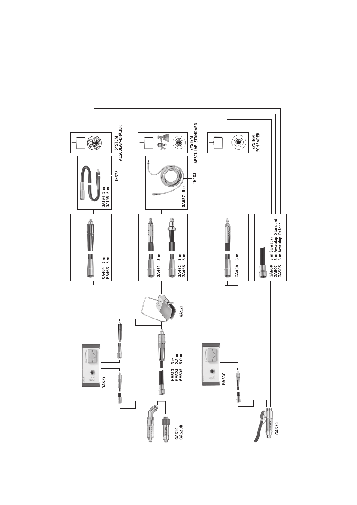
3.1 Components required for operation
When putting the HiLAN XS pneumatic motor into operation, the following components are required
1. Applicable to
► For item-specific instructions for use and information on material
compatibility, see also the Aesculap Extranet at
www.extranet.bbraun.com
2. Safe handling
CAUTION
Federal law restricts this device to sale by, or on order of a physician!
► Remove the transport packaging and clean the new product, either
manually or mechanically, prior to its initial sterilization.
► Prior to use, check that the product is in good working order.
► To prevent damage caused by improper setup or operation, and in order
not to compromise warranty and manufacturer liability:
– Use the product only according to these instructions for use.
– Follow the safety information and maintenance instructions.
– Only combine Aesculap products with each other.
► Ensure that the product and its accessories are operated and used only
by persons with the requisite training, knowledge, or experience.
► Keep the instructions for use accessible for the user.
► Only use handpieces and tools expressly approved for the HiLAN power
system.
Designation Special features Art. no.
Compressed-air supply with a minimum
of 6 bar (0.6 MPa)
Compressed-air tubes Aesculap Dräger system GA464 (3 m),
Foot control GA521
If compressed air is supplied via a compressedgas cylinder, use a pressure reducer
DIN connection GA461 (3 m, with
Motor tube GA513 (3 m)
Pressure reducer:
e.g., GA099
GA466 (5 m)
If needed, extension
tubes GA194 (3 m),
GA195 (5 m)
diffuser)
GA463 (3 m, without diffuser)
GA465 (5 m, without diffuser)
If needed, extension
tube GA087 (5 m)
GA523 (2.3 m)
GA505 (5 m)
If needed, extension
tubes GA194 (3 m),
GA195 (5 m)
HiLAN XS pneumatic
motor
Hi Line XS handpiece
3
Page 6
Aesculap® HiLAN
HiLAN pneumatic motor GA519/GA520R/GA529
3.2 Intended use
The HiLAN pneumatic motors GA519, GA520R, and GA529 are used for
powering the Aesculap Hi-Line handpieces in microsurgery, neurosurgery,
spinal surgery, ENT, and maxillary surgery, as well as in orthopedics.
3.3 Operating principle
3.3.1 HiLAN pneumatic motor
In the HiLAN pneumatic motor, the energy provided by the compressedair supply is converted into rotary movement.
The HiLAN pneumatic motor is equipped with a safety stop, which prevents any unintended startup of the HiLAN pneumatic motor.
3.3.2 Compressed-air tubes
All compressed-air tubes have a fast-lock coupling. Consequently, the
compressed-air tube need not be disconnected from the compressed-air
supply when changing the HiLAN pneumatic motor.
3.3.3 Exit-air recycling via the compressed-air tube
■ Complete exit-air recycling (Aesculap Dräger system): The exit air is
passed outside the operating room. Absence of air turbulence in the
operating room: no effect on either ambient air temperature or
hygiene in the operating room.
■ Partial exit-air recycling (DIN connection and others): The exit air
emerges from the tube end, either directly or through a diffuser inside
the operating room.
3.3.4 Foot control
The foot control GA521 is equipped with a forced ventilation system. As
soon as the foot control pedal is released, the supply air is vented on the
motor side. This allows the HiLAN pneumatic motor to stop more rapidly.
4.1 Compressed-air supply
Danger of fire and explosion when operating
devices that run on oxygen!
DANGER
CAUTION
4.1.1 Operation with central gas supply according to DIN 13260
and EN 737
The gas supply must provide clean, dry air and must be set as follows:
Nominal operating pressure 8 bar
Maximum allowable operating pressure 10 bar
Minimum operating pressure 6 bar
Minimum gas-supply delivery 300 l/min
4.1.2 Operation with compressed-gas cylinders according to
DIN 4664
The following conditions must be met:
► Never operate the HiLAN pneumatic motor with
oxygen.
► Operate the HiLAN pneumatic motor with com-
pressed air or nitrogen.
Operating pressures in excess of 10 bar will damage the HiLAN pneumatic motor!
► Set an operating pressure of between 6 bar and
10 bar.
■ Compressed air or nitrogen is used
■ An adequate stock of full gas cylinders is in place
■ Cylinder pressure reduced to operating pressure of 6 bar to 10 bar
through a pressure reducer (e.g., GA099)
► Operating pressure must be read from the scale on the device and set
with the T-screw.
4. Preparation
Non-compliance with the following instructions will preclude all responsibility and liability in this respect on the part of Aesculap.
► When setting up and operating the product, adhere to
– The national regulations for installation and operation
– National regulations on fire and explosion protection
► Prior to using the HiLAN pneumatic motor and its accessories, check
for any visible damage.
► Use the HiLAN pneumatic motor and its accessories only if they are in
perfect condition.
4
Page 7
5. Working with the HiLAN pneumatic
motor
5.1 System set-up
Injury to the operator and damage to the device
components can result from accidentally putting
WARNING
the HiLAN pneumatic motor into operation!
► Use the safety stop to prevent any accidental
activation of the HiLAN pneumatic motor.
► Only attach handpieces, tools, and the com-
pressed-air supply when the HiLAN pneumatic
motor is shut off.
Detaching the handpiece
► Turn or slide safety stop 20 or slide 18 on the HiLAN pneumatic
motor 1 to position "0".
► Turn threaded ring 24 in the direction of the arrow/rotation in
symbol as far as it will go.
► Remove handpiece 25 or 26 from the HiLAN pneumatic motor 1.
5.1.2 Connecting the compressed-air supply
Long tubes may cause a backup of exit air and thus a loss of performance
of the HiLAN pneumatic motor.
► Keep tube lines as short as possible.
► Make certain that the tube lines are not buckled or crushed.
► Use a suitable extension tube if necessary, see Components required
for operation.
Risk of infection and contamination! The HiLAN
pneumatic motor, its accessories, and the hand-
WARNING
pieces are delivered in an unsterile condition.
► Sterilize the HiLAN pneumatic motor, its acces-
sories, and the handpieces before putting them
into operation.
5.1.1 Connecting the accessories
Combinations of accessories that are not mentioned in the present
instructions for use may only be employed if they are specifically intended
for the respective application, and if they do not compromise the performance and safety characteristics of the products.
► Please contact your B. Braun/Aesculap partner or Aesculap Technical
Service (address: see Technical Service) with any inquiries in this
respect.
Coupling the Hi-Line or Hi-Line-XS handpiece (e.g., GB519R,
GB520R–GB535R, or GB740R-GB758R)
► Turn or slide safety stop 20 or slide 18 on the HiLAN pneumatic
motor 1 to position"0".
► Turn threaded ring 24 in the direction of the arrow/rotation in
symbol as far as it will go.
► Attach the Hi-Line handpiece to the HiLAN pneumatic motor 1 so that
the nibs 21 on the HiLAN pneumatic motor 1 engage in the
notches 23 on handpiece 25. The handpiece can be mounted in 4 different positions.
► Attach Hi-Line XS handpiece 26 to the HiLAN pneumatic motor 1 so
that the pin on the handpiece engages in one of the notches 22 on the
motor. The handpiece can be mounted in 15 different positions.
► Turn threaded ring 24 in the direction of the arrow/rotation in
symbol as far as it will go.
The handpiece is locked now.
► Make certain that the threaded ring is fastened to its limit stop,
because otherwise it may come loose due to vibrations during operation.
Note
The HiLAN pneumatic motors GA519/GA520R and GA529 including the
motor tube are sterile. Sterile separation takes place at the motor tube.
Connecting the HiLAN pneumatic motor at the foot control switch
Coupling:
► Pull back unlocking sleeve (motor-side) 3 on motor tube 5 and connect
the motor tube with its fast-lock coupling (motor-side) 2 to the tube
connection 19 on the HiLAN pneumatic motor 1.
► Release unlocking sleeve (motor-side) 3.
► Insert connector (foot control-side) 6 of motor tube 5 into socket (foot
control-side) 8 on the foot control switch until it engages.
Uncoupling:
► Pull back unlocking sleeve (motor-side) 3 on motor tube 5.
► Remove fast-lock coupling (motor-side) 2 from the HiLAN pneumatic
motor 1.
► Pull back unlocking sleeve (foot control-side) 7 on connector (foot
control-side) 6 of motor tube 5.
► Pull connector (foot control-side) 6 out of socket (foot control-side) 8
on the foot control switch.
5
Page 8

Aesculap® HiLAN
HiLAN pneumatic motor GA519/GA520R/GA529
Note
If coolant pump GA530 is employed for cooling/irrigating the tool blades,
connect the coolant pump between the foot control switch and the HiLAN
pneumatic motor, see TA022140.
Connecting the HiLAN pneumatic motor with hand lever to the compressed-air supply
The HiLAN pneumatic motor GA529 is controlled via hand lever 17 and is
connected to the compressed-air source directly via a tube.
Coupling:
► Make sure that slide 18 is in position "0".
► Select the compressed-air-tube system appropriate for the systems
installed at your site.
► Pull back unlocking sleeve (motor-side) 3 at fast-lock coupling 4 and
attach motor tube 5 to tube connection 19 on the HiLAN pneumatic
motor 1. Pull at 4 to check that the coupling is correct.
► Join connector (source-side) 14 and connecting tube 13 to the com-
pressed-air source in the operating room.
Connecting the foot control switch to the compressed-air supply
Aesculap Dräger system
Coupling:
► Pull back unlocking sleeve (foot control-side) 11 at connecting
tube 13 and connect the tube with fast-lock coupling 12 to connector
(foot control-side) 9 on the foot control switch.
► Release unlocking sleeve (foot control-side) 11.
► Insert connector (source-side) 14 of connecting tube 13 into the
Aesculap Dräger socket until it engages.
Uncoupling:
► Pull back unlocking sleeve (foot control-side) 11 at connecting
tube 13.
► Schnellabsperrkupplung 12 am Stecker (fußschalterseitig) 9 an der
Fußsteuerung abziehen.
► Pull back unlocking sleeve (source-side) 15 at connector (source-
side) 14 of connecting tube 13.
► Pull connector (source-side) 14 out of the Aesculap Dräger socket.
DIN connection
Coupling:
► Pull back unlocking sleeve (foot control-side) 11 at connecting
tube 13 and connect the tube with fast-lock coupling 12 to connector
(foot control-side) 9 on the foot control switch.
► Release unlocking sleeve (foot control-side) 11.
► Insert the DIN connector of connecting tube 13 into the DIN socket
until it engages.
Uncoupling:
► Pull back unlocking sleeve (foot control-side) 11 at connecting
tube 13.
► Remove fast-lock coupling 12 from connector (foot control-side) 9 on
the foot control switch.
► Pull back unlocking sleeve (source-side) 15 at connector (source-
side) 14 of connecting tube 13.
► Pull connector (source-side) 14 out of the DIN socket.
5.2 Function checks
► Always check the pneumatic motor system (HiLAN pneumatic motor,
foot control switch, tubes) by performing a trial run prior to use.
► Make certain that the HiLAN pneumatic motor and foot control switch
are in good working order.
► Make certain that all tubes are properly connected and free of leaks.
6
Page 9
5.3 Safe operation
Risk of burns to patient and user due to hot motor/
hot tool!
WARNING
WARNING
WARNING
WARNING
► Put down the motor/hot tool beyond reach of
the patient.
► Use a cloth to protect against burns when
changing the motor or tool.
Risk of injury and material damage due to inappropriate use of handpieces or motors!
► Always follow the safety advice and information
given in the instructions for use of the handpieces and motors.
► Do not exceed the specified maximum motor
speed.
Risk of injury and/or malfunction!
► Always carry out a function check prior to using
the product.
Danger of damage to patients’ hearing from sound
of motor!
► When using the HiLAN pneumatic motor in
otology, keep as much distance from the ear as
possible.
5.3.1 Operation with the hand lever
► Adjust the length of hand lever 17 to corresponding handpiece 25: To
do this, pull out lever extension 16 to a greater or lesser extent.
► Push slide 18 to position until it engages.
► Carefully press down hand lever 17.
The HiLAN pneumatic motor 1 starts to run.
► Adjusting speed: Press down hand lever 17 to a greater or lesser
extent.
► Maximum speed: Press down hand lever 17 as far as it will go.
► Switching off the HiLAN pneumatic motor, e.g., to change a tool or
handpiece intraoperatively: Turn safety stop 20 until the mark on the
unlocking sleeve is aligned with the “0” mark on the motor.
► Turn safety stop 20 on HiLAN pneumatic motors GA519 and GA520R
until the mark on safety stop 20 is aligned with the "I" mark on the
motor.
► Carefully press down the foot control pedal.
The motor starts running.
► Adjusting speed: Press down on the pedal to a greater or lesser extent.
► To select maximum speed: Press down on the pedal as far as it will go.
► Switching off the HiLAN pneumatic motor, e.g., to change a tool or
handpiece intraoperatively: Turn safety stop 20 until the mark on the
unlocking sleeve is aligned with the “0” mark on the HiLAN pneumatic
motor.
7
Page 10

Aesculap® HiLAN
HiLAN pneumatic motor GA519/GA520R/GA529
6. Validated reprocessing procedure
6.1 General safety instructions
Note
Adhere to national statutory regulations, national and international standards and directives, and local, clinical hygiene instructions for sterile processing.
Note
For patients with Creutzfeldt-Jakob disease (CJD), suspected CJD or possible variants of CJD, observe the relevant national regulations concerning
the reprocessing of products.
Note
Mechanical reprocessing should be favored over manual cleaning as it
gives better and more reliable results.
Note
Successful processing of this medical device can only be ensured if the processing method is first validated. The operator/sterile processing technician is responsible for this.
The recommended chemistry was used for validation.
Note
If there is no final sterilization, then a virucidal disinfectant must be used.
Note
For the latest information on reprocessing and material compatibility see
also the Aesculap extranet at www.extranet.bbraun.com
The validated steam sterilization procedure was carried out in the Aesculap
sterile container system.
6.2 General information
Dried or affixed surgical residues can make cleaning more difficult or ineffective and lead to corrosion. Therefore the time interval between application and processing should not exceed 6 h; also, neither fixating precleaning temperatures >45 °C nor fixating disinfecting agents (active
ingredient: aldehydes/alcohols) should be used.
Excessive measures of neutralizing agents or basic cleaners may result in
a chemical attack and/or to fading and the laser marking becoming
unreadable visually or by machine for stainless steel.
Residues containing chlorine or chlorides e.g. in surgical residues, medicines, saline solutions and in the service water used for cleaning, disinfection and sterilization will cause corrosion damage (pitting, stress corrosion) and result in the destruction of stainless steel products. These must
be removed by rinsing thoroughly with demineralized water and then drying.
Additional drying, if necessary.
Only process chemicals that have been tested and approved (e.g. VAH or
FDA approval or CE mark) and which are compatible with the product’s
materials according to the chemical manufacturers’ recommendations
may be used for processing the product. All the chemical manufacturer's
application specifications must be strictly observed. Failure to do so can
result in the following problems:
■ Optical changes of materials, e.g. fading or discoloration of titanium or
aluminum. For aluminum, the application/process solution only needs
to be of pH >8 to cause visible surface changes.
■ Material damage such as corrosion, cracks, fracturing, premature aging
or swelling.
► Do not use metal cleaning brushes or other abrasives that would dam-
age the product surfaces and could cause corrosion.
► Further detailed advice on hygienically safe and material-/value-pre-
serving reprocessing can be found at www.a-k-i.org, link to Publications, Red Brochure – Proper maintenance of instruments.
6.3 Preparations at the place of use
► Remove any visible surgical residues to the extent possible with a
damp, lint-free cloth.
► Transport the dry product in a sealed waste container for cleaning and
disinfection within 6 hours.
6.4 Preparation before cleaning
► Carry out non-fixating/NaCl-free pre-cleaning immediately after use.
8
Page 11
6.5 Cleaning/disinfection
6.5.1 Product-specific safety instructions for the reprocessing procedure
Fire hazard!
► Do not use flammable or explosive cleaning or
DANGER
CAUTION
CAUTION
disinfecting solutions.
► Ensure that no fluids will penetrate the product.
Damage to the product due to inappropriate cleaning/disinfecting agents!
► Only use cleaning/disinfecting agents approved
for surface cleaning. Follow the manufacturer’s
instructions for the respective cleaning/disinfecting agent.
Damage to the product due to inappropriate cleaning/disinfecting agents and/or excessive temperatures!
► Use cleaning and disinfecting agents according
to the manufacturer’s instructions which
– be approved for plastic material and high-
grade steel,
– do not attack softeners (e.g. in silicone).
– do not cause stress cracks in plastics (e.g.,
PPSU).
► Observe specifications regarding concentration,
temperature and exposure time.
► Do not exceed the maximum permitted cleaning
temperature of 55 °C.
► Dry the product for at least 10 minutes at a maximum of 120 °C.
Note
The indicated drying temperature is a guide temperature only. It must be
checked taking into account the specific conditions (e.g. load) and adjusted
if applicable.
► Do not clean motors/handpieces by ultrasonic treatment and do not
immerse them in any liquids. To avoid the risk of corrosion/malfunctioning, allow any fluid that has entered the product to drain out
immediately.
9
Page 12

Aesculap® HiLAN
HiLAN pneumatic motor GA519/GA520R/GA529
6.5.2 Validated cleaning and disinfection procedure
Validated procedure Special features Reference
Manual cleaning and
wipe disinfection
■ When cleaning instruments with movable hinges, ensure that these
are in an open position and, if applicable, move the joint while cleaning.
■ Drying phase: Use a lint-free cloth
■ Ensure that the product is positioned in such a way that water will
not enter the product e.g. through coupling interfaces. (Immediately
remove any fluid that entered the product inadvertently.)
Mechanical alkaline
cleaning and thermal
disinfecting
6.6 Manual cleaning/disinfecting
► Prior to manual disinfecting, allow water to drip off for a sufficient
length of time to prevent dilution of the disinfecting solution.
► After manual cleaning/disinfection, check visible surfaces visually for
residues.
► Repeat the cleaning/disinfection process if necessary.
6.6.1 Manual cleaning and wipe disinfecting
■ Insert the product in its proper position in the Eccos holder.
■ The products may only be cleaned mechanically with an appropriate
Eccos holder.
Chapter Manual cleaning/disinfecting and subsection:
■ Chapter Manual cleaning and wipe disin-
fecting
Chapter Mechanical cleaning/disinfecting and
subsection:
■ Chapter Mechanical alkaline cleaning and
thermal disinfecting
Phase Step T
[°C/°F]t[min]
I Cleaning RT (cold) - - D–W -
II Drying RT - - - -
III Wipe disinfection - >1 - - Meliseptol HBV wipes 50 % Propan-1-ol
IV Final rinse RT (cold) 0.5 - FD-W -
VDrying RT - - - -
D–W: Drinking water
FD–W: Fully desalinated water (demineralized, low microbiological contamination: drinking water quality at least)
RT: Room temperature
Phase I
► Clean the product under running faucet water, using a suitable clean-
ing brush until all visible residues have been removed from the surfaces.
► Mobilize non-rigid components, such as set screws, links, etc. during
cleaning.
Conc.
[%]
Water quality Chemical
Phase II
► Dry the product in the drying phase with suitable equipment (e.g. cloth,
compressed air), see Validated cleaning and disinfection procedure.
Phase III
► Wipe all surfaces of the product with a single-use disinfectant wipe.
10
Page 13

Phase IV
► After the specified exposure time (at least 1 min), rinse the disinfected
surfaces under running FD water.
► Drain any remaining water fully.
Phase V
► Dry the product in the drying phase with suitable equipment (e.g. cloth,
compressed air), see Validated cleaning and disinfection procedure.
6.7 Mechanical cleaning/disinfecting
Note
The cleaning and disinfection device must be of tested and approved effectiveness (e.g. FDA approval or CE mark according to DIN EN ISO 15883).
Note
The cleaning and disinfection device used for processing must be serviced
and checked at regular intervals.
6.7.1 Mechanical alkaline cleaning and thermal disinfecting
Machine type: single-chamber cleaning/disinfection device without ultrasound
Phase Step T
[°C/°F]t[min]
I Prerinse <25/77 3 D–W -
II Cleaning 55/131 10 FD-W
Water
quality
Chemical/Note
■ Concentrate, alkaline:
–pH = 13
– <5 % anionic surfactant
■ 0.5 % working solution
–pH = 11*
III Intermediate rinse >10/50 1 FD-W -
IV Thermal disinfecting 90/194 5 FD-W -
VDrying - - - According to the program for cleaning and disinfection device
D–W: Drinking water
FD–W: Fully desalinated water (demineralized, low microbiological contamination: drinking water quality at least)
*Recommended: BBraun Helimatic Cleaner alkaline
► Check visible surfaces for residues after mechanical cleaning/disinfect-
ing.
11
Page 14

Aesculap® HiLAN
HiLAN pneumatic motor GA519/GA520R/GA529
6.8 Inspection, maintenance and checks
► Allow the product to cool down to room temperature.
► Inspect the product after each cleaning and disinfecting cycle to be
sure it is: clean, functional, and undamaged.
► Spray through the HiLine motor/handpiece with Aesculap STERILIT oil
spray GB600 with adapter GB600820 until clear oil emerges from the
product.
► Check the product for any damage, abnormal running noise, overheat-
ing or excessive vibration.
► Inspect tools for broken, damaged or blunt edges.
► Set aside the product if it is damaged.
Note
Lubricating the HiLAN pneumatic motors with the original Aesculap oil
spray can lead to oil residues entering the compressed-air tubes. These oil
residues do not harm the materials from which the compressed-air tubes
are made.
6.9 Packaging
► Follow the instructions for use for the applied packaging and storage
systems (e.g. instructions for use TA009721 for Aesculap Eccos storage
system).
► Insert the product in its proper position in the Eccos holder, or put it
on a tray in such a way that the product is protected against damage.
Ensure that all cutting edges are protected.
► Pack trays appropriately for the sterilization process (e.g. in Aesculap
sterile containers).
► Ensure that the packaging will prevent a recontamination of the prod-
uct.
6.11 Sterilization for the US market
■ Aesculap advises against sterilizing the device by flash sterilization or
chemical sterilization.
■ Sterilization may be accomplished by a standard prevacuum cycle in a
steam autoclave.
-6
To achieve a sterility assurance level of 10
following parameters:
Aesculap Orga Tray/Sterile container (perforated bottom)
Minimum cycle parameters*
Sterilization
method
Prevacuum 270 °F/275 °F 4 min 20 min
*Aesculap has validated the above sterilization cycle and has the data on
file. The validation was accomplished in an Aesculap sterile container
cleared by FDA for the sterilization and storage of these products. Other
sterilization cycles may also be suitable, however individuals or hospitals
not using the recommended method are advised to validate any alternative method using appropriate laboratory techniques. Use an FDA cleared
accessory to maintain sterility after processing, such as a wrap, pouch, etc.
Temp. Time Minimum drying time
6.12 Storage
► Store sterile products in germ-proof packaging, protected from dust, in
a dry, dark, temperature-controlled area.
, Aesculap recommends the
6.10 Steam sterilization
Note
Regarding materials and temperatures, the HiLAN pneumatic motors have
been designed for steam sterilization. Consequently, do not sterilize HiLAN
pneumatic motors with hot air or ethylene oxide (EO).
HiLAN pneumatic motors can be sterilized in their storage device.
► Check to ensure that the sterilizing agent will come into contact with
all external and internal surfaces (e.g. by opening any valves and faucets).
► Validated sterilization process
– Disassemble the instrument
– Steam sterilization through fractionated vacuum process
– Steam sterilizer according to DIN EN 285 and validated according
to DIN EN ISO 17665
– Sterilization using fractionated vacuum process at 134 °C/holding
time 5 min
► When sterilizing several instruments at the same time in a steam ster-
ilizer, ensure that the maximum load capacity of the steam sterilizer
specified by the manufacturer is not exceeded.
12
7. Maintenance
To ensure reliable operation, the product must be maintained at least once
a year.
For technical service, please contact your national B. Braun/Aesculap
agency, see Technical Service.
Page 15

8. Troubleshooting list
Malfunction Detection Cause Remedy
HiLAN pneumatic motor not running
Insufficient power Safety stop 20 not set to "I" Insufficient air supply Turn safety stop 20 to "I"
Gas cylinder empty
Manometer set to "0"
No compressed air at the wall outlet
Safety stop 20 set to "0" Turn safety stop 20 to "I"
Slide 18 on hand lever 17 set
to "0"
Tubes not correctly connected Attach fast-lock coupling (motor-
Pedal can be easily pressed or cannot be pressed at all
Hand lever 17 can be easily pressed
or cannot be pressed at all
Operating pressure of central compressed-air supply too low (min.
6bar)
Pressure reducer on gas cylinder
defective
Pressure on pressure reducer set
too low
Tube too long High air resistance in the tube Use shorter tubes
No compressed air Have gas cylinder refilled or
changed
Open valve
Schieber 18 in
Stellung schieben
side) 2 fully
Foot control switch defective Have product repaired by the man-
ufacturer
Hand lever 17 defective Have product repaired by the man-
ufacturer
Have compressed-air supply
checked
Have pressure reducer checked
Set higher pressure
Tubes excessively buckled or
crushed
Exit-air ducting Unblock diffuser and exit-air duct
Motor does not run in spite of correct compressed-air supply
HiLAN pneumatic motor heats up Have product repaired by the man-
HiLAN pneumatic motor not running smoothly
HiLAN pneumatic motor defective Have product repaired by the man-
Do not buckle or crush tubes
ufacturer
ufacturer
Have product repaired by the manufacturer
13
Page 16

Aesculap® HiLAN
HiLAN pneumatic motor GA519/GA520R/GA529
9. Technical Service
Risk of injury and/or malfunction!
► Do not modify the product.
WARNING
► For service and repairs, please contact your national B. Braun/
Aesculapp agency.
Modifications carried out on medical technical equipment may result in
loss of guarantee/warranty rights and forfeiture of applicable licenses.
Service addresses
Aesculap Technischer Service
Am Aesculap-Platz
78532 Tuttlingen / Germany
Phone: +49 (7461) 95 -1601
Fax: +49 (7461) 14 -939
E-Mail: ats@aesculap.de
Or in the US:
Attn. Aesculap Technical Services
615 Lambert Pointe Drive
Hazelwood
MO, 63042 USA
Aesculap Repair Hotline
Phone: +1 (800) 214 -3392
Fax: +1 (314) 895 -4420
Other service addresses can be obtained from the address indicated above.
10. Accessories/Spare parts
Art. no. Designation
GB600 STERILIT Power Systems oil spray
GB600820 STERILIT Power Systems adapter
GA059 Special oil
GA530 HiLAN irrigation pump
GA513R (3 m)
GA523R (2.4 m)
GA505R (5 m)
GA506R (5 m) Motor tube for Aesculap Schrader system
GA507R (5 m) Motor tube for Aesculap standard system
GA521 (gas pedal) Foot control switch
GA194 (3 m)
GA195 (5 m)
GA087 (5 m) Extension tube for Aesculap standard system
GA464 (3 m)
GA466 (5 m)
GA461 (3 m)
GA463 (3 m)
GA465 (5 m)
GA468 (5 m) Connecting tube for Aesculap Schrader sys-
GA508R Angled tube adapter for GA519, GA529
Motor tube for Aesculap Dräger system
Extension tube for Aesculap Dräger system
Connecting tube for Aesculap Dräger system
Connecting tube for Aesculap standard system
tem
14
GB577R Storage (for HiLAN pneumatic motor with
angled tube adapter mounted)
GB559R Storage for motor GA519, GA529
GB560R Storage for motor GA520R
GB564R Storage for motor tube GA513R, GA523R,
GA505R
GB575R Storage for motor tube GA506R
GB576R Storage for motor tube GA507R
JF213R (64 mm) Tray
JK431 Container
GB473 Eccos storage mounting set
Page 17

11. Technical data
Motor type GA519 GA520R GA529
Operating pressure 8 ± 2 bar 8 ± 2 bar 8 ± 2 bar
Max. operating pressure 10 bar 10 bar 10 bar
Air consumption approx. 200 l/min approx. 200 l/min approx. 200 l/min
Max. permissible backup in the exit air 0.7 bar 0.7 bar 0.7 bar
Speed max. 100 000 1/min max. 100 000 1/min max. 110 000 1/min
Noise < 70 dB(A) at 1 m distance < 70 dB(A) at 1 m distance < 70 dB(A) at 1 m distance
Weight approx. 95 g approx. 170 g approx. 132 g
Size ∅ 21 mm x 80 mm ∅ 21 mm x 120 mm ∅ 21 mm x 80 (105) mm
11.1 Ambient conditions
Operation Storage and transport
Temperature
Relative
humidity
Atmospheric
pressure
12. Disposal
Note
The user institution is obliged to process the product before its disposal, see
Validated reprocessing procedure.
13. Distributor in the US/Contact in Canada for product information and complaints
Aesculap Inc.
3773 Corporate Parkway
Center Valley, PA, 18034,
USA
► Detailed information concerning the disposal of the product is avail-
able through your national B. Braun/Aesculap agency, see Technical
Service.
15
Page 18

Aesculap® HiLAN
HiLAN-Druckluftmotor GA519/GA520R/GA529
Aesculap® HiLANHiLAN-Druckluftmotor GA519/GA5 20R/GA529
Legende
Inhaltsverzeichnis
1 HiLAN-Druckluftmotor
2 Schnellabsperrkupplung (motorseitig)
3 Entriegelungshülse (motorseitig)
4 Schnellabsperrkupplung (zum Fassen)
5 Motorschlauch
6 Stecker (fußschalterseitig)
7 Entriegelungshülse (fußschalterseitig)
8 Dose (fußschalterseitig)
9 Stecker (fußschalterseitig)
10 Schlauchkupplung (quellenseitig)
11 Entriegelungshülse (fußschalterseitig)
12 Schnellabsperrkupplung (zum Fassen)
13 Anschlussschlauch für Fußschalter/Wanddose
14 Stecker (quellenseitig)
15 Entriegelungshülse (quellenseitig)
16 Hebelverlängerung
17 Handhebel
18 Schieber
19 Schlauchanschluss
20 Sicherheitsstopp
21 Nasen
22 Aussparungen (Motor)
23 Aussparungen (Handstück)
24 Schraubring
25 Hi-Line-Handstück
26 Hi-Line XS-Handstück
Symbole an Produkt und Verpackung
Achtung, allgemeines Warnzeichen
Achtung, Begleitdokumente beachten
Drehrichtung "rechts" zur Handstück-Entriegelung
Drehrichtung "links" zur Handstück-Verriegelung
I/
0
HiLAN-Druckluftmotor "betriebsbereit"
HiLAN-Druckluftmotor "aus"
1. Geltungsbereich 17
2. Sichere Handhabung 17
3. Gerätebeschreibung 17
3.1 Zum Betrieb erforderliche Komponenten 17
3.2 Verwendungszweck 18
3.3 Funktionsweise 18
HiLAN-Druckluftmotor 18
Druckluftschläuche 18
Abluftrückführung über die Druckluftschläuche 18
Fußsteuerung 18
4. Vorbereiten 18
4.1 Druckluftversorgung 18
Betrieb mit zentraler Gasversorgung nach DIN 13260 und
EN 737 18
Betrieb mit Druckgasflaschen nach DIN 4664 18
5. Arbeiten mit dem HiLAN- Druckluftmotor 19
5.1 Bereitstellen 19
Zubehör anschließen 19
Druckluftversorgung anschließen 19
5.2 Funktionsprüfung 20
5.3 Bedienung 21
Bedienung mit Handhebel 21
6. Validiertes Aufbereitungsverfahren 22
6.1 Allgemeine Sicherheitshinweise 22
6.2 Allgemeine Hinweise 22
6.3 Vorbereitung am Gebrauchsort 22
6.4 Vorbereitung vor der Reinigung 22
6.5 Reinigung/Desinfektion 23
Produktspezifische Sicherheitshinweise zum
Aufbereitungsverfahren 23
Validiertes Reinigungs- und Desinfektionsverfahren 24
6.6 Manuelle Reinigung/Desinfektion 24
Manuelle Reinigung und Wischdesinfektion 24
6.7 Maschinelle Reinigung/Desinfektion 25
Maschinelle alkalische Reinigung und thermische
Desinfektion 25
6.8 Kontrolle, Wartung und Prüfung 26
6.9 Verpackung 26
6.10 Dampfsterilisation 26
6.11 Lagerung 26
7. Instandhaltung 26
8. Fehler erkennen und beheben 27
9. Technischer Service 28
10. Zubehör/Ersatzteile 28
16
Page 19

11. Technische Daten 29
11.1 Umgebungsbedingungen 29
12. Entsorgung 29
1. Geltungsbereich
► Für artikelspezifische Gebrauchsanweisungen und Informationen zur
Materialverträglichkeit siehe auch Aesculap Extranet unter
www.extranet.bbraun.com
2. Sichere Handhabung
► Fabrikneues Produkt nach Entfernung der Transportverpackung und vor
der ersten Sterilisation reinigen (manuell oder maschinell).
► Vor der Anwendung des Produkts Funktionsfähigkeit und ordnungsge-
mäßen Zustand prüfen.
► Um Schäden durch unsachgemäßen Aufbau oder Betrieb zu vermeiden
und die Gewährleistung und Haftung nicht zu gefährden:
– Produkt nur gemäß dieser Gebrauchsanweisung verwenden.
– Sicherheitsinformationen und Instandhaltungshinweise einhalten.
– Nur Aesculap-Produkte miteinander kombinieren.
► Produkt und Zubehör nur von Personen betreiben und anwenden las-
sen, die die erforderliche Ausbildung, Kenntnis oder Erfahrung haben.
► Gebrauchsanweisung für den Anwender zugänglich aufbewahren.
► Nur die für das HiLAN-Motorensystem ausgewiesenen Handstücke und
Werkzeuge verwenden.
3. Gerätebeschreibung
3.1 Zum Betrieb erforderliche Komponenten
Zur Inbetriebnahme des HiLAN XS-Druckluftmotors werden folgende
Komponenten benötigt
Bezeichnung Besonderheiten Art.-Nr.
Druckluftversorgung
mit mind. 6 bar
(0,6 MPa)
Druckluftschläuche Aesculap-Dräger-Sys-
Bei Druckluftversorgung
mit Druckgasflasche
Druckminderer verwenden
tem
DIN-Anschluss GA461 (3 m, mit
Motorschlauch GA513 (3 m)
Druckminderer:
z. B. GA099
GA464 (3 m),
GA466 (5 m)
bei Bedarf Verlängerungsschläuche
GA194 (3 m), GA195
(5 m)
Diffusor)
GA463 (3 m, ohne
Diffusor)
GA465 (5 m, ohne
Diffusor)
bei Bedarf Verlängerungsschlauch
GA087 (5 m)
GA523 (2,3 m)
GA505 (5 m)
bei Bedarf Verlängerungsschläuche
GA194 (3 m), GA195
(5 m)
Fußsteuerung GA521
HiLAN XS-Druckluftmotor
Hi Line XS-Handstück
17
Page 20
Aesculap® HiLAN
HiLAN-Druckluftmotor GA519/GA520R/GA529
3.2 Verwendungszweck
Die HiLAN-Druckluftmotoren GA519, GA520R und GA529 werden als
Antrieb für die Aesculap-Hi-Line-Handstücke in der Mikro-, Neuro-, Wirbelsäulen-, HNO- und Kieferchirurgie sowie in der Orthopädie verwendet.
3.3 Funktionsweise
3.3.1 HiLAN-Druckluftmotor
Der HiLAN-Druckluftmotor wandelt die Energie, die durch die Druckluftversorgung zugeführt wird, in eine rotierende Bewegung um.
Der HiLAN-Druckluftmotor ist mit einem Sicherheitsstopp versehen. Der
Sicherheitsstopp verhindert ein unbeabsichtigtes Anlaufen des HiLANDruckluftmotors.
3.3.2 Druckluftschläuche
Alle Druckluftschläuche besitzen eine Schnellabsperrkupplung. Dadurch
muss der Druckluftschlauch beim Wechseln des HiLAN-Druckluftmotors
nicht von der Druckluftversorgung getrennt werden.
3.3.3 Abluftrückführung über die Druckluftschläuche
■ Vollständige Abluftrückführung (Aesculap-Dräger-System): Die Abluft
wird aus dem OP geleitet. Die Luft verwirbelt nicht im OP, OP-Klima
und Hygiene sind nicht beeinträchtigt.
■ Nichtvollständige Abluftrückführung (DIN-Anschluss und andere): Die
Abluft entweicht am Ende des Schlauchs offen oder über einen Diffusor innerhalb des OPs.
3.3.4 Fußsteuerung
Die Fußsteuerung GA521 ist mit einer Zwangsentlüftung ausgestattet.
Sobald das Pedal der Fußsteuerung losgelassen wird, wird die Zuluft
motorseitig entlüftet. Der HiLAN-Druckluftmotor kommt so schneller zum
Stillstand.
4. Vorbereiten
Wenn die folgenden Vorschriften nicht beachtet werden, übernimmt
Aesculap insoweit keinerlei Verantwortung.
► Beim Aufstellen und Betrieb des Produkts einhalten:
– die nationalen Installations- und Betreiber-Vorschriften
– die nationalen Vorschriften über Brand- und Explosionsschutz
► Vor der Verwendung HiLAN-Druckluftmotor und dessen Zubehör auf
sichtbare Schäden prüfen.
► Nur einwandfreien HiLAN-Druckluftmotor und Zubehörteile einsetzen.
4.1 Druckluftversorgung
Brand- und Explosionsgefahr bei der Verwendung
von Sauerstoff als Antriebsgas!
GEFAHR
VORSICHT
4.1.1 Betrieb mit zentraler Gasversorgung nach DIN 13260 und
EN 737
Die Gasversorgung muss trockene, saubere Luft liefern und wie folgt eingestellt sein:
Nenn-Betriebsdruck 8 bar
Maximal zulässiger Betriebsdruck 10 bar
Mindest-Betriebsdruck 6 bar
► HiLAN-Druckluftmotor nie mit Sauerstoff
antreiben.
► HiLAN-Druckluftmotor mit Druckluft oder
Stickstoff antreiben.
Beschädigung des HiLAN-Druckluftmotors durch
Betriebsdruck über 10 bar!
► Betriebsdruck zwischen 6 bar und 10 bar ein-
stellen.
18
Mindest-Fördermenge der Gasversorgung 300 l/min
4.1.2 Betrieb mit Druckgasflaschen nach DIN 4664
Folgende Voraussetzungen müssen erfüllt sein:
■ Druckluft oder Stickstoff verwendet
■ Ausreichender Vorrat an vollen Gasflaschen vorhanden
■ Flaschendruck mit Druckminderer (z. B. GA099) auf Betriebsdruck von
6 bar bis 10 bar reduziert
► Betriebsdruck auf der geräteseitigen Skala ablesen und an der Knebel-
schraube einstellen.
Page 21
5. Arbeiten mit dem HiLAN- Druckluftmotor
5.1 Bereitstellen
Verletzungen und Sachschäden durch unbeabsichtigtes Betätigen des HiLAN-Druckluftmotors!
WARNUNG
WARNUNG
5.1.1 Zubehör anschließen
Zubehörkombinationen, die nicht in der Gebrauchsanweisung erwähnt
sind, dürfen nur verwendet werden, wenn sie ausdrücklich für die vorgesehene Anwendung bestimmt sind. Leistungsmerkmale sowie Sicherheitsanforderungen dürfen nicht nachteilig beeinflusst werden.
► Bei Fragen wenden Sie sich an Ihren B. Braun/Aesculap-Partner oder
den Aesculap Technischen Service, Adresse siehe Technischer Service.
Hi-Line- bzw. Hi-Line-XS-Handstück kuppeln (z. B. GB519R,
GB520R-GB535R, bzw. GB740R-GB758R)
► Sicherheitsstopp 20 bzw. Schieber 18 am HiLAN-Druckluftmotor 1 in
Stellung "0" drehen bzw. schieben.
► Schraubring 24 bis zum Anschlag in Pfeil-/Drehrichtung des
Symbols drehen.
► Hi-Line-Handstück so auf den HiLAN-Druckluftmotor 1 stecken, dass
die Nasen 21 am HiLAN-Druckluftmotor 1 in die Aussparungen 23 am
Handstück 25 eingreifen. Es sind vier Stellungen des Handstücks möglich.
► Hi-Line XS-Handstück 26 so auf den HiLAN-Druckluftmotor 1 stecken,
dass der Stift am Handstück in eine der Aussparungen 22 am Motor
greift. Es sind 15 Stellungen des Handstücks möglich.
► Schraubring 24 in Pfeil-/Drehrichtung des Symbols bis zum
Anschlag drehen.
Das Handstück ist verriegelt.
► Sicherstellen, dass der Schraubring bis zum Anschlag festgezogen ist,
da er sich sonst während des Betriebs durch Vibrationen lösen kann.
► HiLAN-Druckluftmotor mit Sicherheitsstopp
gegen unbeabsichtigtes Betätigen sichern.
► Handstücke, Werkzeuge und Druckluftversor-
gung nur bei ausgeschaltetem HiLAN-Druckluftmotor anschließen.
Gefahr von Infektionen und Kontaminationen! Der
HiLAN-Druckluftmotor, die Zubehörteile und die
Handstücke werden unsteril geliefert.
► Vor Inbetriebnahme den HiLAN-Druckluftmo-
tor, die Zubehörteile und die Handstücke steril
aufbereiten.
Handstück entkuppeln
► Sicherheitsstopp 20 bzw. Schieber 18 am HiLAN-Druckluftmotor 1 in
Stellung "0" drehen bzw. schieben.
► Schraubring 24 in Pfeil-/Drehrichtung des Symbols bis zum
Anschlag drehen.
► Handstück 25 bzw. 26 vom HiLAN-Druckluftmotor 1 abnehmen.
5.1.2 Druckluftversorgung anschließen
Lange Schläuche können einen Abluft-Rückstau und somit eine Leistungsverringerung des HiLAN-Druckluftmotors verursachen.
► Auf möglichst kurze Schlauchleitungen achten.
► Sicherstellen, dass die Schlauchleitungen nicht geknickt oder
gequetscht werden.
► Falls nötig, passenden Verlängerungsschlauch verwenden, siehe Zum
Betrieb erforderliche Komponenten.
Hinweis
HiLAN-Druckluftmotor GA519/GA520R bzw. GA529 und Motorschlauch
sind steril. Die Steriltrennung erfolgt am Motorschlauch.
HiLAN-Druckluftmotor an Fußschalter anschließen
Kuppeln:
► Entriegelungshülse (motorseitig) 3 am Motorschlauch 5 zurückziehen
und Motorschlauch mit Schnellabsperrkupplung (motorseitig) 2 auf
den Schlauchanschluss 19 am HiLAN-Druckluftmotor 1 stecken.
► Entriegelungshülse (motorseitig) 3 loslassen.
► Stecker (fußschalterseitig) 6 des Motorschlauchs 5 in Dose (fußschal-
terseitig) 8 am Fußschalter einstecken, bis er einrastet.
Entkuppeln:
► Entriegelungshülse (motorseitig) 3 am Motorschlauch 5 zurückziehen.
► Schnellabsperrkupplung (motorseitig) 2 vom HiLAN-Druckluftmotor 1
abziehen.
► Entriegelungshülse (fußschalterseitig) 7 am Stecker
(fußschalterseitig) 6 des Motorschlauchs 5 zurückziehen.
► Stecker (fußschalterseitig) 6 aus der Dose (fußschalterseitig) 8 am
Fußschalter herausziehen.
19
Page 22

Aesculap® HiLAN
HiLAN-Druckluftmotor GA519/GA520R/GA529
Hinweis
Bei Verwendung der Kühlmittelpumpe GA530 zur Kühlung/Spülung der
Werkzeugschneiden, Kühlmittelpumpe zwischen Fußsteuerung und
HiLAN-Druckluftmotor anschließen, siehe TA022140.
HiLAN-Druckluftmotor mit Handhebel an die Druckluftversorgung
anschließen
Der HiLAN-Druckluftmotor GA529 wird über den Handhebel 17 gesteuert
und wird direkt mit einem Schlauch an die Druckluftquelle angeschlossen.
Kuppeln:
► Sicherstellen, dass der Schieber 18 in Stellung "0" steht.
► Je nach Hausinstallation passendes Druckluftschlauchsystem wählen.
► Entriegelungshülse (motorseitig) 3 an Schnellabsperrkupplung 4
zurückziehen und Motorschlauch 5 auf Schlauchanschluss 19 an
HiLAN-Druckluftmotor 1 aufstecken. Durch Ziehen bei 4 kontrollieren,
ob richtig gekuppelt ist.
► Stecker (quellenseitig) 14 und Anschlussschlauch 13 mit Druckluft-
quelle im OP verbinden.
Fußschalter an Druckluftversorgung anschließen
Aesculap-Dräger-System
Kuppeln:
► Entriegelungshülse (fußschalterseitig) 11 am Anschlussschlauch 13
zurückziehen und Schlauch mit Schnellabsperrkupplung 12 auf den
Stecker (fußschalterseitig) 9 an der Fußsteuerung stecken.
► Entriegelungshülse (fußschalterseitig) 11 loslassen.
► Stecker (quellenseitig) 14 des Anschlussschlauchs 13 in Aesculap-
Dräger-Dose stecken, bis er einrastet.
Entkuppeln:
► Entriegelungshülse (fußschalterseitig) 11 am Anschlussschlauch 13
zurückziehen.
► Schnellabsperrkupplung 12 am Stecker (fußschalterseitig) 9 an der
Fußsteuerung abziehen.
► Entriegelungshülse (quellenseitig) 15 am Stecker (quellenseitig) 14
des Anschlussschlauchs 13 zurückziehen.
► Stecker (quellenseitig) 14 aus der Aesculap-Dräger-Dose herauszie-
hen.
DIN-Anschluss
Kuppeln:
► Entriegelungshülse (fußschalterseitig) 11 am Anschlussschlauch 13
zurückziehen und Schlauch mit Schnellabsperrkupplung 12 auf den
Stecker (fußschalterseitig) 9 an der Fußsteuerung stecken.
► Entriegelungshülse (fußschalterseitig) 11 loslassen.
► DIN-Stecker des Anschlussschlauch 13 in DIN-Do se stecken , bis e r ein-
rastet.
Entkuppeln:
► Entriegelungshülse (fußschalterseitig) 11 am Anschlussschlauch 13
zurückziehen.
► Schnellabsperrkupplung 12 Stecker (fußschalterseitig) 9 an der Fuß-
steuerung abziehen.
► Entriegelungshülse (quellenseitig) 15 am Stecker (quellenseitig) 14
des Anschlussschlauchs 13 zurückziehen.
► Stecker (quellenseitig) 14 aus der DIN-Dose herausziehen.
5.2 Funktionsprüfung
► Druckluftmotorsystem (HiLAN-Druckluftmotor, Fußsteuerung, Schläu-
che) vor jedem Einsatz mit einem Probelauf prüfen.
► Sicherstellen, dass HiLAN-Druckluftmotor und Fußsteuerung ord-
nungsgemäß funktionieren.
► Sicherstellen, dass alle Schläuche korrekt gekuppelt und dicht sind.
20
Page 23
5.3 Bedienung
Verbrennungsgefahr für Patienten und Anwender
durch heißen Motor/heißes Werkzeug!
WARNUNG
WARNUNG
WARNUNG
WARNUNG
► Motor/heißes Werkzeug außer Reichweite des
► Beim Wechseln des Motors/Werkzeugs Tuch als
Verletzungsgefahr und Sachschäden durch unsachgemäßen Gebrauch der Handstücke bzw. Antriebe!
► Sicherheitsinformationen und Hinweise in der
► Angegebene maximale Antriebsdrehzahl einhal-
Verletzungsgefahr und/oder Fehlfunktion!
► Vor jedem Gebrauch Funktionsprüfung durch-
Gehörschäden beim Patienten durch Motorlaufgeräusche!
► Bei Einsatz des HiLAN-Druckluftmotors in der
Patienten ablegen.
Schutz vor Verbrennungen verwenden.
Gebrauchsanweisung der Handstücke bzw.
Antriebe einhalten.
ten.
führen.
Otologie möglichst großen Abstand zum Ohr
wählen.
5.3.1 Bedienung mit Handhebel
► Länge des Handhebels 17 auf entsprechendes Handstück 25 einstel-
len: Dazu Hebelverlängerung 16 mehr oder weniger weit herausziehen.
► Schieber 18 in Stellung schieben bis er einrastet.
► Handhebel 17 vorsichtig drücken.
Der HiLAN-Druckluftmotor 1 läuft an.
► Drehzahl regulieren: Handhebel 17 mehr oder weniger stark nieder-
drücken.
► Maximaldrehzahl: Handhebel 17 ganz durchdrücken.
► HiLAN-Druckluftmotor ausschalten, z. B. für intraoperativen Werk-
zeug- oder Handstückwechsel: Sicherheitsstopp 20 drehen, bis die
Markierung der Entriegelungshülse über der am Motor angebrachten
Markierung “0” steht.
► Sicherheitsstopp 20 bei den HiLAN-Druckluftmotoren GA519 und
GA520R drehen, bis die Markierung des Sicherheitsstopps 20 über der
am Motor angebrachten Markierung „I" steht.
► Pedal der Fußsteuerung vorsichtig drücken.
Der Motor setzt sich in Bewegung.
► Drehzahl regulieren: Pedal mehr oder weniger stark drücken.
► Maximaldrehzahl wählen: Pedal ganz durchdrücken.
► HiLAN-Druckluftmotor ausschalten, z. B. für intraoperativen Werk-
zeug- oder Handstückwechsel: Sicherheitsstopp 20 drehen, bis die
Markierung der Entriegelungshülse über der am HiLAN-Druckluftmotor
angebrachten Markierung “0” steht.
21
Page 24

Aesculap® HiLAN
HiLAN-Druckluftmotor GA519/GA520R/GA529
6. Validiertes Aufbereitungsverfahren
6.1 Allgemeine Sicherheitshinweise
Hinweis
Nationale gesetzliche Vorschriften, nationale und internationale Normen
und Richtlinien und die eigenen Hygienevorschriften zur Aufbereitung einhalten.
Hinweis
Bei Patienten mit Creutzfeldt-Jakob-Krankheit (CJK), CJK-Verdacht oder
möglichen Varianten bezüglich der Aufbereitung der Produkte die jeweils
gültigen nationalen Verordnungen einhalten.
Hinweis
Die maschinelle Aufbereitung ist aufgrund eines besseren und sichereren
Reinigungsergebnisses gegenüber der manuellen Reinigung vorzuziehen.
Hinweis
Es ist zu beachten, dass die erfolgreiche Aufbereitung dieses Medizinprodukts nur nach vorheriger Validierung des Aufbereitungsprozesses sichergestellt werden kann. Die Verantwortung hierfür trägt der Betreiber/Aufbereiter.
Zur Validierung wurde die empfohlene Chemie verwendet.
Hinweis
Wenn keine abschließende Sterilisation erfolgt, muss ein viruzides Desinfektionsmittel verwendet werden.
Hinweis
Aktuelle Informationen zur Aufbereitung und zur Materialverträglichkeit
siehe auch Aesculap Extranet unter www.extranet.bbraun.com
Das validierte Dampfsterilisationsverfahren wurde im Aesculap-Sterilcontainer-System durchgeführt.
6.2 Allgemeine Hinweise
Angetrocknete bzw. fixierte OP-Rückstände können die Reinigung
erschweren bzw. unwirksam machen und zu Korrosion führen. Demzufolge sollte ein Zeitraum zwischen Anwendung und Aufbereitung von 6 h
nicht überschritten, sollten keine fixierenden Vorreinigungstemperaturen
>45 °C angewendet und keine fixierenden Desinfektionsmittel (Wirkstoffbasis: Aldehyd, Alkohol) verwendet werden.
Überdosierte Neutralisationsmittel oder Grundreiniger können zu einem
chemischen Angriff und/oder zur Verblassung und visuellen oder maschinellen Unlesbarkeit der Laserbeschriftung bei nicht rostendem Stahl führen.
Bei nicht rostendem Stahl führen Chlor- bzw. chloridhaltige Rückstände
(z. B. OP-Rückstände, Arzneimittel, Kochsalzlösungen, im Wasser zur Reinigung, Desinfektion und Sterilisation) zu Korrosionsschäden (Lochkorrosion, Spannungskorrosion) und somit zur Zerstörung der Produkte. Zur
Entfernung muss eine ausreichende Spülung mit vollentsalztem Wasser
mit anschließender Trocknung erfolgen.
Nachtrocknen, wenn erforderlich.
Es dürfen nur Prozess-Chemikalien eingesetzt werden, die geprüft und
freigegeben sind (z. B. VAH- oder FDA-Zulassung bzw. CE-Kennzeichnung)
und vom Chemikalienhersteller hinsichtlich Materialverträglichkeit empfohlen wurden. Sämtliche Anwendungsvorgaben des Chemikalienherstellers sind strikt einzuhalten. Im anderen Fall kann dies zu nachfolgenden
Problemen führen:
■ Optische Materialveränderungen wie z. B. Verblassen oder Farbverän-
derungen bei Titan oder Aluminium. Bei Aluminium können sichtbare
Oberflächenveränderungen bereits bei einem pH-Wert von >8 in der
Anwendungs-/Gebrauchslösung auftreten.
■ Materialschäden, wie z. B. Korrosion, Risse, Brüche, vorzeitige Alterung
oder Quellung.
► Zur Reinigung keine Metallbürsten oder keine anderen die Oberfläche
verletzenden Scheuermittel verwenden, da sonst Korrosionsgefahr
besteht.
► Weitere detaillierte Hinweise zu einer hygienisch sicheren und materi-
alschonenden/werterhaltenden Wiederaufbereitung, siehe
www.a-k-i.org Rubrik Veröffentlichungen Rote Broschüre – Instrumentenaufbereitung richtig gemacht.
22
6.3 Vorbereitung am Gebrauchsort
► Sichtbare OP-Rückstände möglichst vollständig mit einem feuchten,
flusenfreien Tuch entfernen.
► Produkt trocken in geschlossenem Entsorgungscontainer binnen 6 h
zur Reinigung und Desinfektion transportieren.
6.4 Vorbereitung vor der Reinigung
► Unmittelbar nach der Anwendung nicht fixierende/NaCl-freie Vorreini-
gung durchführen.
Page 25

6.5 Reinigung/Desinfektion
6.5.1 Produktspezifische Sicherheitshinweise zum Aufbereitungsverfahren
Brandgefahr!
► Keine brennbaren und explosiven Reinigungs-
GEFAHR
VORSICHT
VORSICHT
und Desinfektionsmittel verwenden.
► Sicherstellen, dass keine Flüssigkeit in das Pro-
dukt eindringt.
Schäden am Produkt durch ungeeignete Reinigungs-/Desinfektionsmittel!
► Für die Flächenreinigung zugelassene Reini-
gungs-/Desinfektionsmittel nach Anweisung des
Herstellers verwenden.
Schäden am Produkt durch ungeeignete Reinigungs-/Desinfektionsmittel und/oder zu hohe Temperaturen!
► Reinigungs- und Desinfektionsmittel nach
Anweisungen des Herstellers verwenden,
– die für Kunststoffe und Edelstahl zugelassen
sind.
– die keine Weichmacher (z. B. in Silikon)
angreifen.
– die bei Kunststoffen (z. B. PPSU) keine Span-
nungsrisse auslösen.
► Angaben zu Konzentration, Temperatur und Ein-
wirkzeit beachten.
► Maximal zulässige Reinigungstemperatur von
55 °C nicht überschreiten.
► Produkt für mindestens 10 Minuten bei maximal 120 °C trocknen.
Hinweis
Die genannte Trocknungstemperatur dient nur als Richtwert. Sie muss
unter Berücksichtigung der spezifischen Gegebenheiten (z. B. Beladung)
geprüft und ggf. angepasst werden.
► Motoren/Handstücke nicht im Ultraschall-Bad reinigen oder in Flüssig-
keiten einlegen. Eingedrungene Flüssigkeit sofort auslaufen lassen,
sonst Korrosionsgefahr/Funktionsausfall.
23
Page 26

Aesculap® HiLAN
HiLAN-Druckluftmotor GA519/GA520R/GA529
6.5.2 Validiertes Reinigungs- und Desinfektionsverfahren
Validiertes Verfahren Besonderheiten Referenz
Manuelle Reinigung
und Wischdesinfektion
■ Produkt mit beweglichen Gelenken in geöffneter Stellung bzw. unter
Bewegung der Gelenke reinigen.
■ Trocknungsphase: Flusenfreies Tuch verwenden
■ Darauf achten, dass die Lage des Produkts so gewählt wird, dass kein
Wasser, z. B. über Kupplungsansätze, in das Produktinnere eindringt.
(Versehentlich eingedrungene Flüssigkeit sofort entfernen.)
Maschinelle alkalische
Reinigung und thermische Desinfektion
6.6 Manuelle Reinigung/Desinfektion
► Vor der manuellen Desinfektion das Spülwasser ausreichend vom Pro-
dukt abtropfen lassen, um eine Verdünnung der Desinfektionsmittellösung zu verhindern.
► Nach der manuellen Reinigung/Desinfektion einsehbare Oberflächen
visuell auf Rückstände prüfen.
► Falls nötig, den Reinigungs-/Desinfektionsprozess wiederholen.
6.6.1 Manuelle Reinigung und Wischdesinfektion
■ Produkt lagerichtig in die Eccos-Halterung einlegen.
■ Eine maschinelle Reinigung der Produkte ist nur mit entsprechender
Eccos-Halterung zulässig.
Kapitel Manuelle Reinigung/Desinfektion und
Unterkapitel:
■ Kapitel Manuelle Reinigung und Wischdes-
infektion
Kapitel Maschinelle Reinigung/Desinfektion und
Unterkapitel:
■ Kapitel Maschinelle alkalische Reinigung
und thermische Desinfektion
Phase Schritt T
[°C/°F]t[min]
I Reinigung RT (kalt) - - T–W -
II Trocknung RT - - - -
III Wischdesinfektion - >1 - - Meliseptol HBV Tücher 50 % Propan-1-ol
IV Schlussspülung RT (kalt) 0,5 - VE–W -
V Trocknung RT - - - -
T–W: Trinkwasser
VE–W: Vollentsalztes Wasser (demineralisiert, mikrobiologisch mindestens Trinkwasserqualität)
RT: Raumtemperatur
Phase I
► Unter fließendem Leitungswasser mit einer geeigneten Reinigungs-
bürste so lange reinigen, bis auf der Oberfläche keine Rückstände mehr
zu erkennen sind.
► Nicht starre Komponenten, wie z. B. Stellschrauben, Gelenke etc., bei
der Reinigung bewegen.
Konz.
[%]
Wasser-Qualität Chemie
Phase II
► Produkt in der Trocknungsphase mit den geeigneten Hilfsmitteln (z. B.
Tücher, Druckluft) trocknen, siehe Validiertes Reinigungs- und Desinfektionsverfahren.
Phase III
► Produkt vollständig mit Einmal-Desinfektionstuch abwischen.
24
Page 27

Phase IV
► Desinfizierte Oberflächen nach Ablauf der vorgeschriebenen Einwirk-
zeit (mindestens 1 min) unter fließendem VE-Wasser spülen.
► Restwasser ausreichend abtropfen lassen.
Phase V
► Produkt in der Trocknungsphase mit den geeigneten Hilfsmitteln (z. B.
Tücher, Druckluft) trocknen, siehe Validiertes Reinigungs- und Desinfektionsverfahren.
6.7 Maschinelle Reinigung/Desinfektion
Hinweis
Das Reinigungs- und Desinfektionsgerät muss grundsätzlich eine geprüfte
Wirksamkeit besitzen (z. B. FDA-Zulassung bzw. CE-Kennzeichnung entsprechend der DIN EN ISO 15883).
Hinweis
Das eingesetzte Reinigungs- und Desinfektionsgerät muss regelmäßig
gewartet und überprüft werden.
6.7.1 Maschinelle alkalische Reinigung und thermische Desinfektion
Gerätetyp: Einkammer-Reinigungs-/Desinfektionsgerät ohne Ultraschall
Phase Schritt T
[°C/°F]t[min]
IVorspülen <25/77 3 T–W -
II Reinigung 55/131 10 VE–W
WasserQualität
Chemie/Bemerkung
■ Konzentrat, alkalisch:
–pH ~ 13
– <5 % anionische Tenside
■ Gebrauchslösung 0,5 %
–pH ~ 11*
III Zwischenspülung >10/50 1 VE–W -
IV Thermodesinfektion 90/194 5 VE–W -
V Trocknung - - - Gemäß Programm für Reinigungs- und Desinfektionsgerät
T-W: Trinkwasser
VE–W: Vollentsalztes Wasser (demineralisiert, mikrobiologisch mindestens Trinkwasserqualität)
*Empfohlen: BBraun Helimatic Cleaner alcaline
► Nach der maschinellen Reinigung/Desinfektion einsehbare Oberflä-
chen auf Rückstände prüfen.
25
Page 28

Aesculap® HiLAN
HiLAN-Druckluftmotor GA519/GA520R/GA529
6.8 Kontrolle, Wartung und Prüfung
► Produkt auf Raumtemperatur abkühlen lassen.
► Produkt nach jeder Reinigung und Desinfektion prüfen auf: Sauberkeit,
Funktion und Beschädigung.
► HiLine-Motor/-Handstück mit Aesculap-STERILIT-Ölspray GB600 mit
Adapter GB600820 durchsprühen, bis klares Öl austritt.
► Produkt auf Beschädigungen, unregelmäßige Laufgeräusche, übermä-
ßige Erwärmung oder zu starke Vibration prüfen.
► Werkzeug auf abgebrochene, beschädigte und stumpfe Schneiden kon-
trollieren.
► Beschädigtes Produkt sofort aussortieren.
Hinweis
Durch das Ölen der HiLAN-Druckluftmotoren mit Original-AesculapÖlspray können Ölreste in die Druckluftschläuche gelangen. Diese Ölreste
greifen die Materialien der Druckluftschläuche nicht an.
6.9 Verpackung
► Gebrauchsanweisungen der verwendeten Verpackungen und Lagerun-
gen einhalten (z. B. Gebrauchsanweisung TA009721 für AesculapEccos-Lagerungssystem).
► Produkt lagerichtig in die Eccos-Halterung einlegen oder gegen
Beschädigungen geschützt auf Siebkorb legen. Sicherstellen, dass vorhandene Schneiden geschützt sind.
► Siebkörbe dem Sterilisationsverfahren angemessen verpacken (z. B. in
Aesculap-Sterilcontainern).
► Sicherstellen, dass die Verpackung eine Rekontamination des Produkts
verhindert.
6.10 Dampfsterilisation
Hinweis
Die HiLAN-Druckluftmotoren sind von den Werkstoffen und den Temperaturen für die Dampfsterilisation ausgelegt. HiLAN-Druckluftmotoren deshalb nicht mit Heißluft und nicht mit Ethylenoxid (EO) sterilisieren.
Die HiLAN-Druckluftmotoren können in der Lagerung sterilisiert werden.
► Sicherstellen, dass das Sterilisiermittel Zugang zu allen äußeren und
inneren Oberflächen hat (z. B. durch Öffnen von Ventilen und Hähnen).
► Validiertes Sterilisationsverfahren
– Produkt zerlegen
– Dampfsterilisation im fraktionierten Vakuumverfahren
– Dampfsterilisator gemäß DIN EN 285 und validiert gemäß DIN EN
ISO 17665
– Sterilisation im fraktionierten Vakuumverfahren bei 134 °C, Halte-
zeit 5 min
► Bei gleichzeitiger Sterilisation von mehreren Produkten in einem
Dampfsterilisator: Sicherstellen, dass die maximal zulässige Beladung
des Dampfsterilisators gemäß Herstellerangaben nicht überschritten
wird.
6.11 Lagerung
► Sterile Produkte in keimdichter Verpackung staubgeschützt in einem
trockenen, dunklen und gleichmäßig temperierten Raum lagern.
7. Instandhaltung
Um einen zuverlässigen Betrieb zu gewährleisten, muss eine Instandhaltung mindestens einmal jährlich durchgeführt werden.
Für entsprechende Serviceleistungen wenden Sie sich an Ihre nationale
B. Braun/Aesculap-Vertretung, siehe Technischer Service.
26
Page 29

8. Fehler erkennen und beheben
Störung Erkennung Ursache Behebung
HiLAN-Druckluftmotor läuft nicht Flasche leer
Manometer auf "0“
Keine Druckluft an Wandanschluss Ventil öffnen
Sicherheitsstopp 20 steht auf "0“ Sicherheitsstopp 20 auf „I“ drehen
Schieber 18 am Handhebel 17
steht auf „0”
Schläuche nicht richtig angeschlossen
Pedal lässt sich leicht oder gar
nicht betätigen
Handhebel 17 lässt sich leicht oder
gar nicht betätigen
Ungenügende Leistung Sicherheitsstopp 20 steht nicht auf
"I“
Betriebsdruck der zentralen Druckluftversorgung zu gering (min.
6bar)
Druckminderer an Gasflasche
defekt
Zu niedriger Druck an Druckminderer eingestellt
Zu langer Schlauch Hoher Luftwiderstand im Schlauch Kürzere Schläuche verwenden
Keine Druckluft Flasche auffüllen bzw. wechseln
Schieber 18 in
Stellung schieben
Schnellabsperrkupplung
(motorseitig) 2 ganz aufsetzen
Fußschalter defekt Vom Hersteller instand setzen las-
sen
Handhebel 17 defekt Vom Hersteller instand setzen las-
sen
Mangelnde Luftversorgung Sicherheitsstopp 20 auf "I“ drehen
Druckluftversorgung prüfen lassen
Druckminderer prüfen lassen
Höheren Druck einstellen
Schläuche zu stark abgeknickt oder
gequetscht
Verlegung der Abluft Diffusor bzw. Abluftkanal frei
Trotz korrekter Druckluftzuführung
läuft Motor nicht
HiLAN-Druckluftmotor wird heiß Vom Hersteller instand setzen las-
HiLAN-Druckluftmotor läuft nur
ruckartig
HiLAN-Druckluftmotor defekt Vom Hersteller instand setzen las-
Schläuche nicht knicken bzw. quetschen
machen
sen
sen
Vom Hersteller instand setzen lassen
27
Page 30

Aesculap® HiLAN
HiLAN-Druckluftmotor GA519/GA520R/GA529
9. Technischer Service
Verletzungsgefahr und/oder Fehlfunktion!
► Produkt nicht modifizieren.
WARNUNG
► Für Service und Instandsetzung wenden Sie sich an Ihre nationale
B. Braun/Aesculap-Vertretung.
Modifikationen an medizintechnischer Ausrüstung können zu einem Verlust der Garantie-/Gewährleistungsansprüche sowie eventueller Zulassungen führen.
Service-Adressen
Aesculap Technischer Service
Am Aesculap-Platz
78532 Tuttlingen / Germany
Phone: +49 7461 95-1601
Fax: +49 7461 14-939
E-Mail: ats@aesculap.de
Weitere Service-Adressen erfahren Sie über die oben genannte Adresse.
10. Zubehör/Ersatzteile
Art.-Nr. Bezeichnung
GB600 STERILIT-Power-Systems-Ölspray
GB600820 STERILIT-Power-Systems-Adapter
GA059 Spezialöl
GA530 HiLAN Spülpumpe
GA513R (3 m)
GA523R (2,4 m)
GA505R (5 m)
GA506R (5 m) Motorschlauch System Aesculap-Schrader
GA507R (5 m) Motorschlauch System Aesculap-Standard
GA521 (Gaspedal) Fußschalter
GA194 (3 m)
GA195 (5 m)
GA087 (5 m) Verlängerungsschlauch System Aesculap-
GA464 (3 m)
GA466 (5 m)
GA461 (3 m)
GA463 (3 m)
GA465 (5 m)
Motorschlauch System Aesculap-Dräger
Verlängerungsschlauch System AesculapDräger
Standard
Verbindungsschlauch System AesculapDräger
Verbindungsschlauch System Aesculap-Standard
GA468 (5 m) Verbindungsschlauch System Aesculap-
Schrader
GA508R Winkelschlauchadapter für GA519, GA529
GB577R Lagerung (für HiLAN-Druckluftmotor mit
montiertem Winkelschlauchadapter)
GB559R Lagerung für Motor GA519, GA529
GB560R Lagerung für Motor GA520R
GB564R Lagerung für Motorschlauch GA513R,
GA523R, GA505R
GB575R Lagerung für Motorschlauch GA506R
GB576R Lagerung für Motorschlauch GA507R
JF213R (64 mm) Siebkorb
JK431 Container
GB473 Eccos-Lagerungs-Montageset
28
Page 31

11. Technische Daten
Motortyp GA519 GA520R GA529
Betriebsdruck 8 ± 2 bar 8 ± 2 bar 8 ± 2 bar
Max. Betriebsdruck 10 bar 10 bar 10 bar
Luftverbrauch ca. 200 l/min ca. 200 l/min ca. 200 l/min
Max. zulässiger Rückstau in der Abluft 0,7 bar 0,7 bar 0,7 bar
Drehzahl max. 100 000 1/min max. 100 000 1/min max. 110 000 1/min
Lautstärke < 70 dB(A) in 1 m Abstand < 70 dB(A) in 1 m Abstand < 70 dB(A) in 1 m Abstand
Gewicht ca. 95 g ca. 170 g ca. 132 g
Abmessung ∅ 21 mm x 80 mm ∅ 21 mm x 120 mm ∅ 21 mm x 80 (105) mm
11.1 Umgebungsbedingungen
Betrieb Transport und Lagerung
Temperatur
Relative Luftfeuchtigkeit
Atmosphärischer Druck
12. Entsorgung
Hinweis
Das Produkt muss vor der Entsorgung durch den Betreiber aufbereitet werden, siehe Validiertes Aufbereitungsverfahren.
► Bei Fragen bezüglich der Entsorgung des Produkts wenden Sie sich an
Ihre nationale B. Braun/Aesculap-Vertretung, siehe Technischer Service.
29
Page 32

Aesculap® HiLAN
Moteur pneumatique HiLAN GA519/GA520R/GA529
Aesculap® HiLANMoteur pneumatique HiLAN GA 519/GA520R/GA529
Légende
Sommaire
1 Moteur pneumatique HiLAN
2 Raccord de fermeture rapide (côté moteur)
3 Douille de déverrouillage (côté moteur)
4 Raccord de fermeture rapide (pour préhension)
5 Tuyau du moteur
6 Connecteur (côté pédale de commande)
7 Douille de déverrouillage (côté pédale de commande)
8 Prise (côté commande à pédale)
9 Connecteur (côté pédale de commande)
10 Raccord de tuyau (côté source)
11 Douille de déverrouillage (côté pédale de commande)
12 Raccord de fermeture rapide (pour préhension)
13 Tuyau de raccord pour commande à pédale/prise murale
14 Connecteur (côté source)
15 Douille de déverrouillage (côté source)
16 Rallonge de levier
17 Levier manuel
18 Poussoir
19 Raccord de tuyau
20 Arrêt de sécurité
21 Crans
22 Evidements (moteur)
23 Evidements (pièce à main)
24 Anneau vissé
25 Pièce à main Hi-Line
26 Pièce à main Hi-Line XS
Symboles sur le produit et emballage
Attention, symbole général de mise en garde
Attention, tenir compte des documents d’accompagnement
Sens de rotation sur la «droite» pour déverrouiller la
pièce à main
Sens de rotation sur la «gauche» pour verrouiller la
pièce à main
I/
0 Moteur pneumatique HiLAN «off»
Moteur pneumatique HiLAN «prêt à fonctionner»
1. Domaine d'application 31
2. Manipulation sûre 31
3. Description de l’appareil 31
3.1 Composants nécessaires à l’utilisation 31
3.2 Champ d’application 32
3.3 Mode de fonctionnement 32
Moteur pneumatique HiLAN 32
Tuyaux d’air comprimé 32
Evacuation de l'air sortant par les tuyaux d’air comprimé 32
Commande à pied 32
4. Préparation 32
4.1 Alimentation en air comprimé 32
Fonctionnement avec alimentation centrale en gaz suivant
DIN 13260 et EN 737 32
Fonctionnement avec bouteilles d’air comprimé suivant DIN
4664 32
5. Utilisation du moteur pneumatique HiLAN 33
5.1 Mise à disposition 33
Raccord des accessoires 33
Branchement à l’alimentation en air comprimé 33
5.2 Vérification du fonctionnement 34
5.3 Manipulation 35
Manipulation avec levier manuel 35
6. Procédé de traitement stérile validé 36
6.1 Consignes générales de sécurité 36
6.2 Remarques générales 36
6.3 Préparation sur le lieu d’utilisation 36
6.4 Préparation avant le nettoyage 36
6.5 Nettoyage/décontamination 37
Consignes de sécurité spécifiques du produit pour le procédé
de traitement 37
Procédé de nettoyage et de décontamination validé 38
6.6 Nettoyage/décontamination manuels 38
Nettoyage manuel et décontamination par essuyage 38
6.7 Nettoyage/décontamination en machine 39
Nettoyage alcalin en machine et décontamination thermique 39
6.8 Vérification, entretien et contrôle 40
6.9 Emballage 40
6.10 Stérilisation à la vapeur 40
6.11 Stockage 40
7. Maintenance 40
8. Identification et élimination des pannes 41
9. Service Technique 42
30
Page 33

10. Accessoires/pièces de rechange 42
11. Caractéristiques techniques 43
11.1 Conditions ambiantes 43
12. Elimination 43
3. Description de l’appareil
3.1 Composants nécessaires à l’utilisation
Pour la mise en service du moteur pneumatique HiLAN XS, les composants
suivants sont nécessaires
1. Domaine d'application
► Pour obtenir le mode d’emploi d’un article ou des informations sur la
compatibilité des matériaux, voir aussi l’extranet d’Aesculap à l’adresse
suivante: www.extranet.bbraun.com
2. Manipulation sûre
► Nettoyer (à la main ou en machine) le produit neuf sortant d’usine
après le retrait du conditionnement de transport et avant la première
stérilisation.
► Vérifier le bon fonctionnement et le bon état du produit avant de l’uti-
liser.
► Pour éviter les dommages provoqués par un montage ou une utilisation
incorrects et ne pas remettre en cause les droits à prestations de
garantie et la responsabilité:
– N’utiliser ce produit que conformément au présent mode d’emploi.
– Respecter les informations sur la sécurité et les consignes de main-
tenance.
– Ne combiner entre eux que des produits Aesculap.
► Confier le fonctionnement et l’utilisation du produit et des accessoires
uniquement à des personnes disposant de la formation, des connaissances ou de l’expérience requises.
► Le mode d’emploi doit être conservé en un lieu accessible à l’utilisateur.
► Utiliser uniquement les pièces à main et outils spécialement prévus
pour le système de moteur HiLAN.
Désignation Particularités Art. n°
Alimentation en air
comprimé d’au moins
6 bar (0,6 MPa)
Tuyaux d’air comprimé
Commande à pied GA521
Utiliser un manodétendeur pour l’alimentation
en air comprimé avec
une bouteille d’air comprimé
Système AesculapDräger
Raccord DIN GA461 (3 m, avec
Tuyau du moteur GA513 (3 m)
Manodétendeur:
p. ex. GA099
GA464 (3 m),
GA466 (5 m)
si nécessaire tuyaux
de rallonge GA194
(3 m), GA195 (5 m)
diffuseur)
GA463 (3 m, sans
diffuseur)
GA465 (5 m, sans
diffuseur)
le cas échéant tuyau
de rallonge GA087
(5 m)
GA523 (2,3 m)
GA505 (5 m)
si nécessaire tuyaux
de rallonge GA194
(3 m), GA195 (5 m)
Moteur pneumatique
HiLAN XS
Pièce à main Hi Line
XS
31
Page 34

Aesculap® HiLAN
Moteur pneumatique HiLAN GA519/GA520R/GA529
3.2 Champ d’application
Les moteurs pneumatiques HiLAN GA519, GA520R et GA529 sont utilisés
comme entraînement pour les pièces à main Hi-Line d’Aesculap en microchirurgie, en neurochirurgie, en chirurgie vertébrale, ORL et maxillaire
ainsi qu’en orthopédie.
3.3 Mode de fonctionnement
3.3.1 Moteur pneumatique HiLAN
Le moteur pneumatique HiLAN transforme en mouvements rotatifs l’énergie fournie par l'alimentation en air comprimé.
Le moteur pneumatique HiLAN est équipé d’un arrêt de sécurité. L’arrêt de
sécurité empêche une mise en marche involontaire du moteur pneumatique HiLAN.
3.3.2 Tuyaux d’air comprimé
Tous les tuyaux d’air comprimé possèdent un raccord de fermeture rapide.
Il n’est ainsi pas nécessaire de séparer le tuyau d’air comprimé de l’alimentation en air comprimé lors du changement de moteur pneumatique
HiLAN.
3.3.3 Evacuation de l'air sortant par les tuyaux d’air comprimé
■ Evacuation intégrale de l'air sortant (système Aesculap-Dräger): l'air
sortant est évacué hors de la salle d'opération. Pas de tourbillons d'air
dans la salle d'opération, il n’y a pas d'influence négative sur la qualité
de l'air et sur l'hygiène de la salle d'opération.
■ Evacuation partielle de l’air sortant (raccord DIN et autres): l'air sor-
tant s'échappe à l'extrémité du tuyau, directement ou en passant par
un diffuseur, à l'intérieur de la salle d'opération.
3.3.4 Commande à pied
La commande à pied GA521 est équipée d’une purge forcée. Dès que la
pédale de la commande à pied est relâchée, l’air d’arrivée est purgé côté
moteur. Le moteur pneumatique HiLAN s’arrête ainsi plus rapidement.
4.1 Alimentation en air comprimé
Danger d’incendie et d’explosion en cas d’utilisation d’oxygène comme gaz d’entraînement!
DANGER
ATTENTION
4.1.1 Fonctionnement avec alimentation centrale en gaz suivant
DIN 13260 et EN 737
L'alimentation en gaz doit fournir un air sec et propre et être réglée selon
les paramètres suivants:
Pression de service nominale 8 bar
Pression de service maximale admissible 10 bar
Pression de service minimale 6 bar
Débit minimal de l’alimentation en gaz 300 l/min
4.1.2 Fonctionnement avec bouteilles d’air comprimé suivant DIN
4664
Les conditions suivantes doivent être remplies:
► Ne jamais faire fonctionner le moteur pneuma-
tique HiLAN à l’oxygène.
► Faites fonctionner le moteur pneumatique
HiLAN avec de l’air comprimé ou de l’azote.
Risque de détérioration du moteur pneumatique
HiLAN en cas de pression de service supérieure à
10 bar!
► Régler la pression de service entre 6 bar et
10 bar.
■ Utilisation d’air comprimé ou d’azote
■ Réserve suffisante de bouteilles de gaz pleines
■ Pression de bouteille réduite par manodétendeur (p.ex. GA099) à une
pression de service de 6 à 10 bar
► Lire la pression de service sur l’échelle située sur l’appareil et la régler
au moyen de la vis à garrot.
4. Préparation
Aesculap n’assume aucune responsabilité lorsque les obligations suivantes
ne sont pas respectées.
► Pour installer et faire fonctionner le produit, observer:
– les directives nationales relatives à l’installation et au fonctionne-
ment,
– les réglementations nationales relatives à la protection contre les
incendies et les explosions.
► Avant l’utilisation du moteur pneumatique HiLAN et de ses accessoires,
vérifiez l’absence de dommages visibles.
► Utilisez uniquement un moteur pneumatique HiLAN et des accessoires
en parfait état.
32
Page 35

5. Utilisation du moteur pneumatique
HiLAN
5.1 Mise à disposition
Risque de blessures et de dégâts matériels par
actionnement involontaire du moteur pneumatique
AVERTISSEMENT
AVERTISSEMENT
5.1.1 Raccord des accessoires
Les combinaisons d’accessoires non mentionnées dans le mode d’emploi
ne peuvent être utilisées que si elles sont expressément prévues pour
l’application projetée. Ceci ne doit pas porter préjudice aux caractéristiques de puissance ni aux exigences de sécurité.
► Pour toutes questions, adressez-vous à votre partenaire B. Braun/
Aesculap ou au Service Technique Aesculap, l’adresse voir Service
Technique.
Accouplement des pièces à main Hi-Line ou Hi-Line-XS (p. ex.
GB519R, GB520R-GB535R, ou GB740R-GB758R)
► Tourner ou pousser l’arrêt de sécurité 20 ou le poussoir 18 sur le
moteur pneumatique HiLAN 1 sur la position "0".
► Tourner l’anneau vissé 24 jusqu’à la butée dans le sens de rotation/de
la flèche du symbole .
► Ficher la pièce à main Hi-Line sur le moteur pneumatique HiLAN 1 de
manière à ce que les crans 21 sur le moteur pneumatique HiLAN 1
s’engagent dans les évidements 23 de la pièce à main 25. Quatre positions de la pièce à main sont possibles.
► Ficher la pièce à main Hi-Line XS 26 sur le moteur pneumatique
HiLAN 1 de sorte que la broche de la pièce à main s’engage dans l’un
des évidements 22 du moteur. 15 positions de la pièce à main sont
possibles.
► Tourner l’anneau vissé 24 jusqu’à la butée dans le sens de rotation/de
la flèche du symbole .
La pièce à main est accouplée.
► Vérifier que l’anneau vissé est serré à fond pour qu’il ne puisse se déta-
cher par vibrations pendant la marche.
HiLAN!
► Assurer le moteur pneumatique HiLAN contre
une mise en marche involontaire avec l’arrêt de
sécurité.
► Ne raccorder les pièces à main, les outils et l’ali-
mentation en air comprimé que lorsque le
moteur pneumatique HiLAN est éteint.
Risque d’infection et de contamination! Le moteur
pneumatique HiLAN, les accessoires et les pièces à
main sont livrés non stériles.
► Avant la mise en service, procéder au traitement
stérile du moteur pneumatique HiLAN, de ses
accessoires et des pièces à main.
Désaccouplement de la pièce à main
► Tourner ou pousser l’arrêt de sécurité 20 ou le poussoir 18 sur le
moteur pneumatique HiLAN 1 sur la position "0".
► Tourner l’anneau vissé 24 jusqu’à la butée dans le sens de rotation/de
la flèche du symbole .
► Retirer la pièce à main 25 ou 26 du moteur pneumatique HiLAN 1.
5.1.2 Branchement à l’alimentation en air comprimé
Des tuyaux longs peuvent provoquer un reflux de l’air sortant et entraîner
ainsi une baisse de puissance du moteur pneumatique HiLAN.
► Veiller à ce que les conduites par tuyaux soient les plus courtes pos-
sibles.
► Veiller à ce que les conduites par tuyaux ne soient pas pliées ni com-
primées.
► Si nécessaire, utiliser un tuyau de rallonge, voir Composants néces-
saires à l’utilisation.
Remarque
Le moteur pneumatique HiLAN GA519/GA520R ou GA529 et le tuyau du
moteur sont stériles. La séparation stérile se fait au niveau du tuyau du
moteur.
Raccord du moteur pneumatique HiLAN à la commande à pédale
Accouplement:
► Tirer vers l’arrière la douille de déverrouillage (côté moteur) 3 sur le
tuyau du moteur 5 et ficher le tuyau du moteur avec raccord de fermeture rapide (côté moteur) 2 sur le raccord de tuyau 19 du moteur
pneumatique HiLAN 1.
► Relâcher la douille de déverrouillage (côté pédale) 3.
► Brancher le connecteur (côté pédale) 6 du tuyau du moteur 5 dans la
prise (côté pédale) 8 de la commande à pédale jusqu’à ce qu’il
s’engage.
Désaccouplement:
► Tirer vers l’arrière la douille de déverrouillage (côté moteur) 3 sur le
tuyau du moteur 5.
► Retirer le raccord de fermeture rapide (côté moteur) 2 du moteur
pneumatique HiLAN 1.
► Tirer vers l’arrière la douille de déverrouillage (côté pédale) 7 du
connecteur (côté pédale) 6 du tuyau du moteur 5.
► Retirer le connecteur (côté pédale) 6 de la prise (côté pédale) 8 sur la
commande à pédale.
33
Page 36

Aesculap® HiLAN
Moteur pneumatique HiLAN GA519/GA520R/GA529
Remarque
En cas d’utilisation de la pompe à agent de refroidissement GA530 pour le
refroidissement/l’irrigation des tranchants d’outil, brancher la pompe à
agent de refroidissement entre la commande à pied et le moteur pneumatique HiLAN, voir TA022140.
Raccord du moteur pneumatique HiLAN avec levier manuel à l’alimentation en air comprimé
Le moteur pneumatique HiLAN GA529 est commandé par l’intermédiaire
du levier manuel 17 et directement raccordé par un tuyau à la source d’air
comprimé.
Accouplement:
► Vérifier que le poussoir 18 est sur la position "0".
► Choisir le système de tuyaux d’air comprimé adapté à l’installation du
local.
► Tirer vers l’arrière la douille de déverrouillage (côté moteur) 3 du rac-
cord de fermeture rapide 4 et ficher le tuyau du moteur 5 sur le raccord de tuyau 19 du moteur pneumatique HiLAN 1. Contrôler par une
traction sur 4 que l’accouplement est correct.
► Connecter le connecteur (côté source) 14 et le tuyau de raccord 13 à
la source d’air comprimé du bloc opératoire.
Raccord de la commande à pédale à l’alimentation en air comprimé
Système Aesculap-Dräger
Accouplement:
► Tirer vers l’arrière la douille de déverrouillage (côté pédale) 11 sur le
tuyau de raccord 13 et ficher le tuyau avec raccord de fermeture
rapide 12 sur le connecteur (côté pédale) 9 de la commande à pied.
► Relâcher la douille de déverrouillage (côté pédale) 11.
► Ficher le connecteur (côté source) 14 du tuyau de raccord 13 dans la
prise Aesculap-Dräger jusqu’à ce qu’il s’engage.
Désaccouplement:
► Tirer vers l’arrière la douille de déverrouillage (côté pédale) 11 sur le
tuyau de raccord 13.
► Schnellabsperrkupplung 12 am Stecker (fußschalterseitig) 9 an der
Fußsteuerung abziehen.
► Tirer vers l’arrière la douille de déverrouillage (côté source) 15 sur le
connecteur (côté source)14 du tuyau de raccord 13.
► Retirer le connecteur (côté source) 14 de la prise Aesculap-Dräger.
Raccord DIN
Accouplement:
► Tirer vers l’arrière la douille de déverrouillage (côté pédale) 11 sur le
tuyau de raccord 13 et ficher le tuyau avec raccord de fermeture
rapide 12 sur le connecteur (côté pédale) 9 de la commande à pied.
► Relâcher la douille de déverrouillage (côté pédale) 11.
► Ficher le connecteur DIN du tuyau de raccord 13 dans la prise DIN
jusqu’à ce qu’il s’engage.
Désaccouplement:
► Tirer vers l’arrière la douille de déverrouillage (côté pédale) 11 sur le
tuyau de raccord 13.
► Retirer le raccord de fermeture rapide 12 du connecteur (côté
pédale) 9 de la commande à pied.
► Tirer vers l’arrière la douille de déverrouillage (côté source) 15 sur le
connecteur (côté source) 14 du tuyau de raccord 13.
► Retirer le connecteur (côté source) 14 de la prise DIN.
5.2 Vérification du fonctionnement
► Avant chaque utilisation, contrôlez le système de moteur pneumatique
(moteur pneumatique HiLAN, commande à pied, tuyaux) par une
marche d'essai.
► Vérifiez que le moteur pneumatique HiLAN et la commande à pied
fonctionnent correctement.
► Vérifier que tous les tuyaux sont bien raccordés et étanches.
34
Page 37

5.3 Manipulation
Risque de brûlure pour le patient et l’utilisateur, dû
au moteur/aux outil brûlants!
AVERTISSEMENT
AVERTISSEMENT
AVERTISSEMENT
AVERTISSEMENT
► Poser le moteur/l’outil brûlant hors de portée du
patient.
► Pour le remplacement du moteur/de l’outil, uti-
liser une pièce textile comme protection contre
les brûlures.
Risque de blessure et de dommages matériels en cas
d’utilisation impropre des pièces à main et des
entraînements!
► Respecter les informations et les consignes de
sécurité des modes d'emploi des pièces à main et
des entraînements.
► Respecter la vitesse de rotation maximale indi-
quée pour l’entraînement.
Risque de blessure et/ou de dysfonctionnement!
► Procéder à un contrôle du fonctionnement
avant chaque utilisation.
Risque de troubles auditifs chez le patient en raison
des bruits du fonctionnement du moteur!
► En cas d’utilisation du moteur pneumatique
HiLAN en otologie, maintenir une distance aussi
grande que possible par rapport à l’oreille.
5.3.1 Manipulation avec levier manuel
► Ajuster la longueur du levier manuel 17 en fonction de la pièce à
main 25: pour cela, déployer plus ou moins la rallonge de levier 16.
► Pousser le poussoir de sécurité 18 en position jusqu’à ce qu’il
s’engage.
► Appuyer avec précautions sur le levier manuel 17.
Le moteur pneumatique HiLAN 1 démarre.
► Régulation du régime: abaisser plus ou moins fortement le levier
manuel 17.
► Régime maximal: appuyer à fond sur le levier manuel 17.
► Mise à l’arrêt du moteur pneumatique HiLAN, p. ex. pour le change-
ment d’outil ou de pièce à main pendant l’opération: Tourner l’arrêt de
sécurité 20 jusqu’à ce que le repère sur la douille de déverrouillage se
trouve au-dessus du repère "0" sur le moteur.
► Tourner l’arrêt de sécurité 20 sur les moteurs pneumatiques HiLAN
GA519 et GA520R, jusqu’à ce que le repère de l’arrêt de sécurité 20 se
trouve au-dessus du repère "I" sur le moteur.
► Presser avec précaution la pédale de la commande à pied.
Le moteur se met en mouvement.
► Régulation du régime: appuyer plus ou moins fort sur la pédale.
► Sélection du régime maximal: appuyer à fond sur la pédale.
► Mise à l’arrêt du moteur pneumatique HiLAN, p. ex. pour le change-
ment d’outil ou de pièce à main pendant l’opération: Tourner l’arrêt de
sécurité 20 jusqu’à ce que le repère sur la douille de déverrouillage se
trouve au-dessus du repère "0" sur le moteur pneumatique HiLAN.
35
Page 38

Aesculap® HiLAN
Moteur pneumatique HiLAN GA519/GA520R/GA529
6. Procédé de traitement stérile validé
6.1 Consignes générales de sécurité
Remarque
En matière de traitement stérile, respecter les prescriptions légales nationales, les normes et directives nationales et internationales ainsi que les
propres dispositions relatives à l’hygiène.
Remarque
Pour les patients atteints de la maladie de Creutzfeldt-Jakob (CJ), soupçonnés d’être atteints de CJ ou d’éventuelles variantes, respecter les réglementations nationales en vigueur pour la préparation stérile des produits.
Remarque
Le traitement stérile en machine doit être préféré au nettoyage manuel du
fait de résultats de nettoyage meilleurs et plus fiables.
Remarque
On notera que la réussite du traitement stérile de ce produit médical ne
peut être garantie qu’après validation préalable du procédé de traitement
stérile. La responsabilité en incombe à l’exploitant/au responsable du traitement stérile.
Pour la validation, les produits chimiques recommandés ont été utilisés.
Remarque
Si aucune stérilisation finale n'a lieu, des produits de décontamination
virocides doivent être utilisés.
Remarque
Pour des informations actuelles sur le traitement stérile et la compatibilité
avec les matériaux, voir également l'Extranet Aesculap à l'adresse
www.extranet.bbraun.com
Le procédé validé de stérilisation à la vapeur a été réalisé dans le système
de conteneurs stériles Aesculap.
6.2 Remarques générales
Les résidus opératoires incrustés ou fixés peuvent faire obstacle au nettoyage ou le rendre inefficace et entraîner une corrosion. Un intervalle de
6 h entre utilisation et traitement stérile ne devrait par conséquent pas
être dépassé, de même qu’il ne faut pas appliquer de températures de prélavage fixantes >45 °C ni utiliser de produits désinfectants fixants (substance active: aldéhyde, alcool).
Un surdosage du produit de neutralisation ou du détergent de base peut
entraîner une agression chimique et/ou le palissement et l’illisibilité
visuelle ou mécanique de l’inscription laser sur l’acier inoxydable.
Sur l’acier inoxydable, les résidus contenant du chlore ou des chlorures
(p. ex. les résidus opératoires, médicaments, solutions salines, eau pour le
nettoyage, la décontamination et la stérilisation) entraînent des dégâts
dus à la corrosion (corrosion perforatrice, sous contrainte) et donc la
dégradation des produits. Les résidus sont éliminés par rinçage suffisamment abondant à l’eau déminéralisée et séchage consécutif.
Sécher ensuite si nécessaire.
Seuls doivent être utilisés des produits chimiques de traitement contrôlés
et validés (p. ex. agrément VAH ou FDA ou marquage CE) et recommandés
par le fabricant des produits chimiques quant à la compatibilité avec les
matériaux. Toutes les prescriptions d’application du fabricant des produits
chimiques doivent être strictement respectées. Dans le cas contraire, les
problèmes suivants peuvent survenir:
■ Modification d’aspect du matériau, p. ex. palissement ou altérations de
couleur du titane ou de l’aluminium. Sur l’aluminium, des altérations
de surface visibles peuvent se produire dès une valeur de pH de >8 dans
la solution utilisée.
■ Détériorations de matériau telles que corrosion, fissures, cassures,
vieillissement prématuré ou dilatations.
► Pour le nettoyage, ne pas utiliser de brosses métalliques, ni d’autres
produits abrasifs pouvant abîmer la surface, faute de quoi il y a risque
de corrosion.
► Pour des informations plus détaillées sur un retraitement hygiénique-
ment sûr qui ménage les matériaux et conserve leur valeur aux produits, consulter www.a-k-i.org à la rubrique “Veröffentlichungen Rote
Broschüre” - Le traitement correct des instruments de chirurgie.
36
6.3 Préparation sur le lieu d’utilisation
► Retirer si possible complètement les résidus opératoires visibles avec
un chiffon humide non pelucheux.
► Pour le nettoyage et la décontamination, transporter le produit sec
dans un container d’élimination des déchets fermé dans un délai de
6h.
6.4 Préparation avant le nettoyage
► Effectuer immédiatement après l’utilisation un nettoyage préalable
non fixant et sans NaCl.
Page 39

6.5 Nettoyage/décontamination
6.5.1 Consignes de sécurité spécifiques du produit pour le procédé
de traitement
Risque d’incendie!
► Ne pas utiliser de produits de nettoyage et de
DANGER
ATTENTION
ATTENTION
décontamination inflammables et explosifs.
► Contrôler qu’aucun liquide ne pénètre dans le
produit.
Risque de détériorations du produit du fait d’un
produit de nettoyage/décontamination inadéquat!
► Utiliser uniquement des produits de nettoyage/
décontamination agréés pour le nettoyage des
surfaces en respectant les instructions du fabricant.
Risque de détérioration du produit avec un produit
de nettoyage/décontamination inadéquat et/ou des
températures trop élevées!
► Utiliser en respectant les instructions du fabri-
cant des produits de nettoyage et de décontamination
– agréés pour les matières plastiques et l’acier
spécial.
– qui n’attaquent pas les plastifiants (p. ex. en
silicone).
– qui déclenchent des fissures par contrainte
sur les matières synthétiques (p. ex. le PPSU).
► Respecter les indications sur la concentration, la
température et le temps d’action.
► Ne pas dépasser la température de nettoyage
maximale autorisée de 55 °C.
► Sécher le produit pendant au moins 10 minutes à 120 °C maximum.
Remarque
La température de séchage n’est donnée qu’à titre indicatif. Elle devra être
vérifiée et adaptée si nécessaire en tenant compte des circonstances spécifiques (p. ex. chargement).
► Ne pas nettoyer les moteurs/pièces à main dans un bain aux ultrasons
ni les plonger dans des liquides. Faire immédiatement s’écouler le
liquide ayant pénétré, faute de quoi il y a risque de corrosion/de panne
de fonctionnement.
37
Page 40

Aesculap® HiLAN
Moteur pneumatique HiLAN GA519/GA520R/GA529
6.5.2 Procédé de nettoyage et de décontamination validé
Procédé validé Particularités Réf. dorsale
Nettoyage manuel et
décontamination par
essuyage
■ Nettoyer le produit en ouvrant les articulations mobiles ou en les
actionnant.
■ Phase de séchage: Utiliser un chiffon non pelucheux
■ Veiller à choisir pour le produit une position dans laquelle il est
impossible que de l’eau ne pénètre à l’intérieur du produit, p. ex. via
les embouts d’accouplement. (immédiatement éliminer le liquide
ayant pénétré par erreur.)
Nettoyage alcalin en
machine et décontamination thermique
6.6 Nettoyage/décontamination manuels
► Avant de procéder à la décontamination manuelle, laisser l’eau de rin-
çage s’égoutter suffisamment du produit afin d’éviter une dilution de
la solution de décontamination.
► Après le nettoyage/la décontamination manuels, vérifier par contrôle
visuel la présence éventuelle de résidus sur les surfaces visibles.
► Si nécessaire, répéter le processus de nettoyage/décontamination.
6.6.1 Nettoyage manuel et décontamination par essuyage
■ Poser le produit en position correcte dans la fixation Eccos.
■ Le nettoyage en machine des produits est uniquement autorisé en cas
d'utilisation d'une fixation Eccos correspondante.
Chapitre Nettoyage/décontamination manuels
et sous-chapitre:
■ Chapitre Nettoyage manuel et décontamina-
tion par essuyage
Chapitre Nettoyage/décontamination en
machine et sous-chapitre:
■ Chapitre Nettoyage alcalin en machine et
décontamination thermique
Phase Etape T
[°C/°F]t[min]
I Nettoyage TA
(froid)
II Séchage TA - - - -
III Décontamination par
essuyage
IV Rinçage final TA
VSéchage TA - - - -
EP: Eau potable
EDém: Eau déminéralisée (au moins de qualité eau potable du point de vue microbiologique)
TA: Température ambiante
Phase I
► Nettoyer le produit sous l’eau courante avec une brosse de nettoyage
appropriée jusqu’à ce qu’aucun résidu ne soit plus visible sur la surface.
► Pendant le nettoyage, faire bouger les composants non rigides tels que
vis de réglage, articulations, etc.
38
- >1 - - Chiffons Meliseptol HBV propane-1-ol 50 %
(froid)
-- EP -
0,5 - EDém -
Conc.
[%]
Qualité de l’eau Chimie
Phase II
► Sécher le produit dans la phase de séchage avec les moyens adaptés
(p. ex. lingettes, air comprimé), voir Procédé de nettoyage et de décontamination validé.
Page 41

Phase III
► Essuyer entièrement le produit avec un chiffon décontaminant à usage
unique.
Phase IV
► Rincer les surfaces décontaminées sous de l'eau déminéralisée cou-
rante après le temps d’action prescrit (au moins 1 minute).
► Laisser s’égoutter suffisamment l’eau résiduelle.
Phase V
► Sécher le produit dans la phase de séchage avec les moyens adaptés
(p. ex. lingettes, air comprimé), voir Procédé de nettoyage et de décontamination validé.
6.7 Nettoyage/décontamination en machine
Remarque
L’appareil de nettoyage et de décontamination doit posséder en tout état
de cause une efficacité contrôlée (p. ex. agrément FDA ou marquage CE
conformément à la norme DIN EN ISO 15883).
Remarque
L'appareil de nettoyage et de décontamination utilisé doit être régulièrement entretenu et contrôlé.
6.7.1 Nettoyage alcalin en machine et décontamination thermique
Type d’appareil: appareil de nettoyage/décontamination à une chambre sans ultrasons
Phase Etape T
[°C/°F]t[min]
I Rinçage préalable <25/77 3 EP -
II Nettoyage 55/131 10 EDém
Qualité
de l’eau
Chimie/remarque
■ Concentré, alcalin:
–pH ~ 13
– <5 % de dérivés tensioactifs anioniques
■ Solution d’usage 0,5 %
–pH ~ 11*
III Rinçage intermédiaire >10/50 1 EDém -
IV Thermodécontamina-
tion
VSéchage - - - Selon le programme pour l'appareil de nettoyage et de décontamination
EP: Eau potable
EDém: Eau déminéralisée (au moins de qualité eau potable du point de vue microbiologique)
*Recommandé: BBraun Helimatic Cleaner alcalin
► Après le nettoyage/la décontamination en machine, vérifier la présence
éventuelle de résidus sur les surfaces visibles.
90/194 5 EDém -
39
Page 42

Aesculap® HiLAN
Moteur pneumatique HiLAN GA519/GA520R/GA529
6.8 Vérification, entretien et contrôle
► Laisser refroidir le produit à la température ambiante.
► Après chaque nettoyage et décontamination, vérifier sur le produit les
éléments suivants: propreté, bon fonctionnement et absence de détériorations.
► Vaporiser de part en part le moteur/la pièce à la main HiLine avec le
spray d'huile Aesculap-STERILIT GB600 à l'aide de l'adaptateur
GB600820, jusqu’à ce que de l’huile claire en sorte.
► Contrôler sur le produit l’absence de détériorations, de bruits de fonc-
tionnement irréguliers, d’échauffement excessif et de trop fortes vibrations.
► Vérifier que les tranchants de l’outil ne sont pas rompus, endommagés
ou émoussés.
► Mettre immédiatement au rebut le produit endommagé.
Remarque
Par le huilage des moteurs pneumatiques HiLAN avec le spray d’huile
Aesculap d’origine, des résidus d’huile peuvent pénétrer dans les tuyaux
d’air comprimé. Ces résidus d’huile n’attaquent pas les matériaux des
tuyaux d’air comprimé.
6.9 Emballage
► Respecter les modes d’emploi des emballages et des rangements utili-
sés (p. ex. mode d’emploi TA009721 pour le système de rangement
Aesculap Eccos).
► Placer le produit en position correcte dans la fixation Eccos ou le poser
sur le panier perforé en le protégeant contre les détériorations. Veiller
à ce que les éventuels tranchants soient protégés.
► Emballer les paniers perforés de manière adaptée au procédé de stéri-
lisation (p. ex. dans des containers de stérilisation Aesculap).
► Veiller à ce que l’emballage empêche une recontamination du produit.
6.10 Stérilisation à la vapeur
Remarque
Les moteurs pneumatiques HiLAN sont conçus pour la stérilisation à la
vapeur pour ce qui est des matériaux et de la température. Pour cette raison, ne pas stériliser les moteurs pneumatiques HiLAN à l’air chaud ni à
l’oxyde d’éthylène (EO).
Les moteurs pneumatiques HiLAN peuvent être stérilisés dans le rangement.
► Veiller à ce que le produit de stérilisation ait accès à toutes les surfaces
extérieures et intérieures (p. ex. en ouvrant les valves et les robinets).
► Procédé de stérilisation validé
– Démonter le produit
– Stérilisation à la vapeur avec procédé du vide fractionné
– Stérilisateur à la vapeur selon DIN EN 285 et validé selon DIN EN
ISO 17665
– Stérilisation par procédé du vide fractionné à 134 °C, durée de
maintien de 5 min
► En cas de stérilisation simultanée de plusieurs produits dans un stéri-
lisateur à vapeur: veiller à ce que le chargement maximal autorisé du
stérilisateur à vapeur indiqué par le fabricant ne soit pas dépassé.
6.11 Stockage
► Stocker les produits stériles en emballage étanche aux germes, proté-
gés contre la poussière, dans une pièce sèche, obscure et de température homogène.
7. Maintenance
Pour garantir un fonctionnement fiable, il faut effectuer au moins une
maintenance par an.
Pour les prestations de service correspondantes, adressez-vous à votre
représentation nationale B. Braun/Aesculap, voir Service Technique.
40
Page 43

8. Identification et élimination des pannes
Problème Identification Cause Elimination
Le moteur pneumatique HiLAN ne
fonctionne pas
Puissance insuffisante L'arrêt de sécurité 20 n'est pas sur
Bouteille vide
Manomètre sur «0»
Pas d’air comprimé au raccord
mural
L’arrêt de sécurité 20 est sur la
position «0»
Le poussoir 18 du levier manuel 17
est sur la position «0»
Tuyaux mal raccordés Bien enfoncer le raccord de ferme-
Actionnement faible ou nul de la
pédale
Le levier manuel 17 ne peut être
actionné que légèrement ou pas du
tout
"I"
Pression de service de l’alimentation centrale en air comprimé trop
faible (min. 6 bar)
Détendeur sur la bouteille de gaz
défectueux
Pas d’air comprimé Remplir ou remplacer la bouteille
Ouvrir la vanne
Tourner l’arrêt de sécurité 20 sur
"I"
Schieber 18 in
Stellung schieben
ture rapide (côté moteur) 2
Commande à pédale défectueuse Réparation par le fabricant
Levier manuel 17 défectueux Réparation par le fabricant
Alimentation insuffisante en air Tourner l'arrêt de sécurité 20 sur
"I"
Faire vérifier l’alimentation en air
comprimé
Faire contrôler le détendeur
Trop faible pression réglée sur le
détendeur
Tuyau trop long Résistance de l’air élevée dans le
Tuyaux trop fortement pliés ou
comprimés
Déplacement de l’air sortant Dégager le diffuseur ou le canal
Le moteur ne fonctionne pas malgré une arrivée correcte de l’air
comprimé
Le moteur pneumatique HiLAN
chauffe
Le moteur pneumatique HiLAN ne
fonctionne que par à-coups
tuyau
Moteur pneumatique HiLAN défectueux
Régler une pression plus élevée
Utiliser des tuyaux plus courts
Ne pas plier ni comprimer les
tuyaux
d’évacuation de l’air
Réparation par le fabricant
Réparation par le fabricant
Réparation par le fabricant
41
Page 44

Aesculap® HiLAN
Moteur pneumatique HiLAN GA519/GA520R/GA529
9. Service Technique
Risque de blessure et/ou de dysfonctionnement!
► Ne pas modifier le produit.
AVERTISSEMENT
► Pour le service et la réparation, veuillez vous adresser à votre distribu-
teur national B. Braun/Aesculap.
Les modifications effectuées sur les équipements techniques médicaux
peuvent entraîner une perte des droits à garantie de même que d’éventuelles autorisations.
Adresses de service
Aesculap Technischer Service
Am Aesculap-Platz
78532 Tuttlingen / Germany
Phone: +49 7461 95-1601
Fax: +49 7461 14-939
E-Mail: ats@aesculap.de
Pour obtenir d’autres adresses de service, contactez l’adresse ci-dessus.
10. Accessoires/pièces de rechange
Art. n° Désignation
GB600 Spray d’huile STERILIT Power Systems
GB600820 Adaptateur STERILIT Power Systems
GA059 Huile spéciale
GA530 Pompe d’irrigation HiLAN
GA513R (3 m)
GA523R (2,4 m)
GA505R (5 m)
GA506R (5 m) Tuyau de moteur système Aesculap-Schrader
GA507R (5 m) Tuyau de moteur système Aesculap-Standard
GA521 (pédale de gaz) Commande au pied
GA194 (3 m)
GA195 (5 m)
GA087 (5 m) Tuyau de rallonge système Aesculap-Stan-
GA464 (3 m)
GA466 (5 m)
GA461 (3 m)
GA463 (3 m)
GA465 (5 m)
Tuyau de moteur système Aesculap-Dräger
Tuyau de rallonge système Aesculap-Dräger
dard
Tuyau de jonction système Aesculap-Dräger
Tuyau de jonction système Aesculap-Standard
GA468 (5 m) Tuyau de jonction système Aesculap-Schra-
der
GA508R Adaptateur coudé pour tuyau pour GA519,
GA529
GB577R Rangement (pour moteur pneumatique
HiLAN avec adaptateur coudé pour tuyau
monté)
GB559R Rangement pour moteur GA519, GA529
GB560R Rangement pour moteur GA520R
GB564R Rangement pour tuyau de moteur GA513R,
GA523R, GA505R
GB575R Rangement pour tuyau de moteur GA506R
GB576R Rangement pour tuyau de moteur GA507R
JF213R (64 mm) Panier grillagé
JK431 Container
GB473 Kit de montage de rangement Eccos
42
Page 45

11. Caractéristiques techniques
Type de moteur GA519 GA520R GA529
Pression de service 8 ± 2 bar 8 ± 2 bar 8 ± 2 bar
Pression de service max. 10 bar 10 bar 10 bar
Consommation d’air env. 200 l/min env. 200 l/min env. 200 l/min
Reflux maximal autorisé dans la conduite
d’air sortant
Régime 100 000 1/min max. 100 000 1/min max. 110 000 1/min max.
Puissance sonore < 70 dB(A) à 1 m de distance < 70 dB(A) à 1 m de distance < 70 dB(A) à 1 m de distance
Poids env. 95 g env. 170 g env. 132 g
Dimensions ∅ 21 mm x 80 mm ∅ 21 mm x 120 mm ∅ 21 mm x 80 (105) mm
0,7 bar 0,7 bar 0,7 bar
11.1 Conditions ambiantes
Fonctionnement Transport et stockage
Température
Humidité relative de l'air
Pression
atmosphérique
12. Elimination
Remarque
Avant son évacuation, le produit doit avoir été traité par l’exploitant, voir
Procédé de traitement stérile validé.
► Pour toute question portant sur l’évacuation du produit, veuillez vous
adresser à votre représentation nationale B. Braun/Aesculap, voir Service Technique.
43
Page 46

Aesculap® HiLAN
Motor neumático HiLAN GA519/GA520R/GA529
Aesculap® HiLANMotor neumático HiLAN GA519/GA520R/ GA529
Leyenda
Índice
1 Motor neumático HiLAN
2 Acoplamiento de cierre rápido (lado del motor)
3 Casquillo de desenclavamiento (lado del motor)
4 Acoplamiento de cierre rápido (para sujeción)
5 Tubo del motor
6 Conector macho (lado del pedal)
7 Casquillo de desenclavamiento (lado del pedal)
8 Conector hembra (lado del pedal)
9 Conector macho (lado del pedal)
10 Acoplamiento para tubo (lado de la fuente)
11 Casquillo de desenclavamiento (lado del pedal)
12 Acoplamiento de cierre rápido (para sujeción)
13 Tubo de conexión para pedal/base de enchufe de la pared
14 Conector (lado de la fuente)
15 Casquillo de desenclavamiento (lado de la fuente)
16 Prolongación de la palanca
17 Palanca
18 Introducir la corredera
19 Boquilla
20 Girar el bloqueo de seguridad
21 Salientes
22 Escotaduras (motor)
23 Escotaduras (pieza de mano)
24 Anillo roscado
25 Pieza de mano Hi-Line
26 Pieza de mano Hi-Line XS
Símbolos en el producto y envase
Atención, señal de advertencia general
Atención, observar la documentación adjunta
Girar a la derecha para desbloquear la pieza de mano
Girar a la izquierda para bloquear la pieza de mano
I/
0
Motor neumático HiLAN ”listo para funcionar”
Motor neumático HiLAN "apagado"
1. Campo de aplicación 45
2. Manipulación correcta 45
3. Descripción del aparato 45
3.1 Componentes necesarios para el servicio 45
3.2 Finalidad de uso 46
3.3 Modo de funcionamiento 46
Motor neumático HiLAN 46
Tubos neumáticos 46
Recirculación del aire de escape mediante los tubos
neumáticos 46
Mando de pedal 46
4. Preparación 46
4.1 Alimentación de aire comprimido 46
Funcionamiento con sistema central de alimentación de gas
según DIN 13260 y EN 737 46
Funcionamiento con botellas de gas comprimido según DIN
4664 46
5. Utilizar el motor neumático HiLAN 47
5.1 Puesta a punto 47
Conexión de los accesorios 47
Conectar la alimentación de aire comprimido 47
5.2 Comprobación del funcionamiento 48
5.3 Manejo del producto 49
Manejo con palanca 49
6. Proceso homologado del tratamiento de instrumental
quirúrgico 50
6.1 Advertencias de seguridad generales 50
6.2 Indicaciones generales 50
6.3 Preparación en el lugar de uso 50
6.4 Preparación previa a la limpieza 50
6.5 Limpieza/Desinfección 51
Advertencias específicas de seguridad a la hora de realizar el
proceso de tratamiento. 51
Proceso homologado de limpieza y desinfección 52
6.6 Limpieza/desinfección manuales 52
Limpieza manual y desinfección con un paño 52
6.7 Limpieza/Desinfección automáticas 53
Limpieza alcalina automática y desinfección térmica 53
6.8 Control, mantenimiento e inspección 54
6.9 Envase 54
6.10 Esterilización a vapor 54
6.11 Almacenamiento 54
7. Conservación 54
8. Identificación y subsanación de fallos 55
9. Servicio de Asistencia Técnica 56
44
Page 47

10. Accesorios/piezas de recambio 56
11. Datos técnicos 57
11.1 Condiciones ambientales 57
12. Eliminación de residuos 57
3. Descripción del aparato
3.1 Componentes necesarios para el servicio
Para poner en funcionamiento el motor neumático se necesitan los
siguientes componentes HiLAN XS
1. Campo de aplicación
► Para consultar información actualizada sobre la compatibilidad con el
material, visite también Aesculap nuestra extranet en la siguiente
dirección www.extranet.bbraun.com
2. Manipulación correcta
► Limpiar a mano o a máquina el producto nuevo de fábrica después de
haberlo desembalado y antes de la primera esterilización.
► Antes de utilizar el producto comprobar que funcione y que se encuen-
tre en perfecto estado.
► Para evitar daños causados por un montaje o uso inadecuados y con-
servar así los derechos de garantía y responsabilidad del fabricante:
– Utilizar el producto sólo conforme a las presentes instrucciones de
uso.
– Respetar la información sobre las medidas de seguridad y las ins-
trucciones de mantenimiento.
– Sólo combinar entre sí productos Aesculap.
► Confiar la aplicación y el uso del producto y de los accesorios exclusi-
vamente a personal con la formación requerida para ello o que disponga de los conocimientos o experiencia necesarios.
► Conservar las instrucciones en un lugar accesible para el operario.
► Con el sistema a motor HiLAN, utilizar sólo las piezas de mano y herra-
mientas indicadas.
Descripción Particularidades N.º art.
Alimentación de aire
comprimido de al
menos 6 bar (0,6 MPa)
Tubos neumáticos Sistema Aesculap-
En la alimentación de
aire comprimido utilizar
un manorreductor con
botella de aire comprimido
Dräger
Conexión DIN GA461 (3 m, con
Tubo del motor GA513 (3 m)
Manorreductor:
p. ej. GA099
GA464 (3 m),
GA466 (5 m)
si es necesario, las
prolongaciones
GA194 (3 m) o
GA195 (5 m)
difusor)
GA463 (3 m, sin
difusor)
GA465 (5 m, sin
difusor)
si es necesario, la
prolongación
GA087 (5 m)
GA523 (2,3 m)
GA505 (5 m)
si es necesario, las
prolongaciones
GA194 (3 m) o
GA195 (5 m)
Mando de pedal GA521
Motor neumático
HiLAN XS
Pieza de mano Hi Line
XS
45
Page 48

Aesculap® HiLAN
Motor neumático HiLAN GA519/GA520R/GA529
3.2 Finalidad de uso
Los motores neumáticos HiLAN GA519, GA520R y GA529 se utilizan para
accionar las piezas de mano Hi-Line de Aesculapen microcirugía, neurocirugía, cirugía de la columna vertebral, cirugía otorrinolaringológica, cirugía maxilofacial y ortopedia.
3.3 Modo de funcionamiento
3.3.1 Motor neumático HiLAN
El motor neumático HiLAN transforma la energía suministrada por el sistema de alimentación de aire comprimido en movimiento rotatorio.
El motor neumático HiLAN va provisto de un bloqueo de seguridad. El bloqueo de seguridad evita el accionamiento involuntario del motor neumático HiLAN.
3.3.2 Tubos neumáticos
Todos los tubos neumáticos cuentan con un acoplamiento de cierre rápido.
Gracias a este acoplamiento no es necesario desconectar el tubo neumático de la alimentación de aire comprimido para cambiar el motor neumático HiLAN.
3.3.3 Recirculación del aire de escape mediante los tubos neumáticos
■ Recirculación completa del aire de escape (Sistema Aesculap-Dräger):
El aire se extrae del quirófano de forma que no se arremolina en éste y
no se perjudican el ambiente ni la higiene del mismo.
■ Recirculación incompleta del aire de escape (conexión DIN y otros
modelos): El aire de escape sale por el extremo del tubo libremente o
a través del difusor y se queda en el quirófano.
3.3.4 Mando de pedal
El mando de pedal GA521 va provisto de un sistema de purga forzada. Al
soltar el pedal de mando, se purga el aire del conducto de entrada al
motor. De este modo, el motor neumático HiLAN se detendrá con mayor
rapidez.
4.1 Alimentación de aire comprimido
Riesgo de provocar incendios y explosiones si se
utiliza oxígeno como gas propulsor existe.
PELIGRO
ATENCIÓN
4.1.1 Funcionamiento con sistema central de alimentación de gas
según DIN 13260 y EN 737
El sistema central de alimentación de gas deberá proveer de aire seco y
limpio y deberá ajustarse del siguiente modo:
Presión de trabajo nominal 8 bar
Presión máxima de trabajo permitida 10 bar
Presión mínima de trabajo 6 bar
Caudal mínimo de aire suministrado 300 l/min
4.1.2 Funcionamiento con botellas de gas comprimido según DIN
4664
Deben cumplirse las condiciones previas siguientes:
► No accionar el motor neumático HiLAN con oxí-
geno bajo ningún concepto.
► Accionar el motor neumático HiLAN con aire
comprimido o con nitrógeno.
Se correrá el riesgo de ocasionar daños al motor
neumático HiLAN si la presión de trabajo sobrepasa
los 10 bar.
► Ajustar la presión de trabajo entre 6 bar y
10 bar.
■ Utilización de aire comprimido o nitrógeno
■ Reserva suficiente de botellas de gas llenas
■ Presión de la botella con manorreductor (p. ej.GA099) reducida a una
presión de trabajo de 6-10bar
► Leer la presión de trabajo que indica la escala del aparato y ajustarla
mediante un tornillo de muletilla.
4. Preparación
Si no se observan las siguientes normas, Aesculap declina cualquier responsabilidad.
► Al instalar y poner en funcionamiento el producto, deberán respetarse:
– los reglamentos de instalación y operación vigentes a nivel nacional
– las normas nacionales sobre prevención de incendios y explosiones
► Comprobar que no haya daños visibles antes de utilizar el motor neu-
mático HiLAN y sus accesorios.
► Utilizar únicamente motores neumáticos y accesorios HiLAN en per-
fecto estado.
46
Page 49

5. Utilizar el motor neumático HiLAN
5.1 Puesta a punto
Un accionamiento involuntario del motor neumático HiLAN puede provocar lesiones y daños mate-
ADVERTENCIA
ADVERTENCIA
5.1.1 Conexión de los accesorios
Las combinaciones de accesorios no mencionadas en las instrucciones de
uso sólo podrán ser utilizadas si están expresamente destinadas para la
aplicación prevista. No deben influir negativamente en las características
de rendimiento ni en los requisitos de seguridad.
► En caso de duda, consultar a la persona de contacto correspondiente
de B. Braun/Aesculap o al Servicio de Asistencia Técnica de Aesculap,
dirección: ver Servicio de Asistencia Técnica.
Acoplamiento de las piezas de mano Hi-Line y Hi-Line-XS (p. ej.,
GB519R, GB520R-GB535R, o GB740R-GB758R)
► Poner o deslizar el bloqueo de seguridad 20 o la corredera 18 del
motor neumático HiLAN 1 en posición "0".
► Girar el anillo roscado 24 hasta el tope en el sentido de la flecha/de
giro del símbolo .
► Acoplar la pieza de mano Hi-Line en el motor neumático HiLAN 1 de
forma que los salientes 21 del motor neumático HiLAN 1 en las
escotaduras 23 de la pieza de mano 25. La pieza de mano tiene cuatro
posiciones.
► Insertar la pieza de mano Hi-Line XS 26 en el motor neumático
HiLAN 1 de tal manera que la clavija de la pieza de mano se agarre a
las escotaduras 22 del motor. La pieza de mano tiene 15 posiciones.
► Girar el anillo roscado 24 hasta el tope en el sentido de la flecha/de
giro del símbolo .
La pieza de mano está bloqueada.
► Asegurarse de que el anillo roscado está apretado al máximo ya que,
de lo contrario, éste podría aflojarse por las vibraciones durante el funcionamiento.
riales
► Asegurar el motor neumático HiLAN contra un
accionamiento involuntario con el bloqueo de
seguridad.
► Conectar las piezas de mano, los útiles y la ali-
mentación de aire al motor neumático HiLAN
sólo cuando esté desactivado.
Peligro de infecciones y contaminaciones. El motor
neumático HiLAN, sus accesorios y piezas de mano
se suministran sin esterilizar.
► Antes de la puesta en servicio, esterilizar el
motor neumático HiLAN, los accesorios y las
piezas de mano.
Desacoplamiento de la pieza de mano
► Poner o deslizar el bloqueo de seguridad 20 o la corredera 18 del
motor neumático HiLAN 1 en posición "0".
► Girar el anillo roscado 24 hasta el tope en el sentido de la flecha/de
giro del símbolo .
► Retirar la pieza de mano 25 o 26 del motor neumático HiLAN 1.
5.1.2 Conectar la alimentación de aire comprimido
Los tubos de gran longitud pueden provocar un remanso en el escape de
aire y, como consecuencia, una disminución de la potencia del motor neumático HiLAN.
► Procurar utilizar los tubos más cortos posible.
► Asegurarse de que los tubos no tienen dobleces ni aplastamientos.
► Utilizar, si es necesario, la prolongación adecuada, ver Componentes
necesarios para el servicio.
Nota
Los motores neumáticos HiLAN GA519/GA520R y GA529 y el tubo del
motor son estériles. El resto de componentes no son estériles.
Conexión del motor neumático HiLAN al sistema de alimentación de
aire comprimido
Acoplamiento:
► Retirar el casquillo de desenclavamiento (lado del motor) 3 situado en
el tubo del motor 5 y conectar el tubo del motor con el acoplamiento
de cierre rápido (lado del motor) 2 a la conexión de aire
comprimido 19 del motor neumático HiLAN 1.
► Soltar el casquillo de desenclavamiento (lado del motor) 3.
► Introducir el conector macho (lado del pedal) 6 del tubo del motor 5
en el conector hembra (lado del pedal) 8 del pedal hasta que quede
enclavado.
Desacoplamiento:
► Retirar el casquillo de desenclavamiento (lado del motor) 3 del tubo
del motor 5.
► Separar el acoplamiento de cierre rápido (lado del motor) 2 del motor
neumático HiLAN 1.
► Retirar el casquillo de desenclavamiento (lado del pedal) 7 del conec-
tor macho (lado del pedal) 6 del tubo del motor 5.
► Retirar el conector macho (lado del pedal) 6 del conector hembra (lado
del pedal) 8 del pedal.
47
Page 50

Aesculap® HiLAN
Motor neumático HiLAN GA519/GA520R/GA529
Nota
Cuando se utiliza la bomba de líquido refrigerante GA530 para la refrigeración/lavado de los filos del útil, conectar la bomba de líquido refrigerante
entre el mando de pedal y el motor neumático HiLAN, ver TA022140.
Conexión del motor neumático HiLANcon palanca al sistema de alimentación de aire comprimido
El motor neumático HiLAN GA529 se controla a través de la palanca 17 y
se conecta directamente mediante un tubo a la fuente de aire comprimido.
Acoplamiento:
► Asegurarse de que la corredera 18 se encuentra en la posición “0”.
► Utilizar el sistema de alimentación de aire comprimido adecuado para
la instalación.
► Retirar el casquillo de desenclavamiento (lado del motor) 3 del acopla-
miento de cierre rápido 4 y conectar el tubo del motor 5 a la
boquilla 19 del motor neumático HiLAN 1. Controlar si el conjunto 4
está bien acoplado tirando del acoplamiento
► Unir el conector (lado de la fuente) 14 y el tubo de conexión 13 a la
fuente de aire comprimido del quirófano.
Conexión del pedal al sistema de alimentación de aire comprimido
Sistema Aesculap-Dräger
Acoplamiento:
► Retirar el casquillo de desenclavamiento (lado del pedal) 11 situado en
el tubo de conexión 13 y conectar el tubo del motor con el acoplamiento de cierre rápido 12 al conector macho (lado del pedal) 9
situado en el mando de pedal.
► Soltar el casquillo de desenclavamiento (lado del pedal) 11.
► Introducir el conector macho (lado de la fuente) 14 del tubo de
conexión 13 en el conector hembra DIN Aesculap-Dräger hasta que
quede enclavado.
Desacoplamiento:
► Retirar el casquillo de desenclavamiento (lado del pedal) 11 situado en
el tubo de conexión 13.
► Schnellabsperrkupplung 12 am Stecker (fußschalterseitig) 9 an der
Fußsteuerung abziehen.
► Retirar el casquillo de desenclavamiento (lado de la fuente) 15 del
conector macho (lado de la fuente) 14 del tubo de conexión 13.
► Retirar el conector macho (lado de la fuente) 14 del conector hembra
Aesculap-Dräger.
Conexión DIN
Acoplamiento:
► Retirar el casquillo de desenclavamiento (lado del pedal) 11 situado en
el tubo de conexión 13 y conectar el tubo del motor con el acoplamiento de cierre rápido 12 al conector macho (lado del pedal) 9
situado en el mando de pedal.
► Soltar el casquillo de desenclavamiento (lado del pedal) 11.
► Introducir el conector macho DIN del tubo de conexión 13 en el conec-
tor hembra DIN hasta que quede enclavado.
Desacoplamiento:
► Retirar el casquillo de desenclavamiento (lado del pedal) 11 situado en
el tubo de conexión 13.
► Extraer el acoplamiento de cierre rápido 12 Retirar el conector macho
(lado del pedal) 9 situado en el mando de pedal.
► Retirar el casquillo de desenclavamiento (lado de la fuente) 15 del
conector macho (lado de la fuente) 14 del tubo de conexión 13.
► Retirar el conector macho (lado de la fuente) 14 del conector hembra.
5.2 Comprobación del funcionamiento
► El sistema completo de motor neumático (motor neumático HiLAN,
mando de pedal, tubos flexibles) debe someterse siempre a una prueba
de funcionamiento antes de su uso.
► Asegurarse de que el motor neumático HiLAN y el mando de pedal fun-
cionan correctamente.
► Asegurarse de que todos los tubos flexibles se han acoplado correcta-
mente y que no tienen fugas.
48
Page 51

5.3 Manejo del producto
Peligro de quemaduras para los pacientes y para el
usuario por calentamiento del motor/del útil.
ADVERTENCIA
ADVERTENCIA
ADVERTENCIA
ADVERTENCIA
► Mantener el motor/el útil caliente fuera del
alcance del paciente.
► Al cambiar el motor/el útil utilizar un paño para
protegerse de posibles quemaduras.
Peligro de lesiones y de daños materiales por un
manejo inadecuado de las piezas de mano y de los
accionamientos.
► Respetar la información y las advertencias de
seguridad indicadas en las instrucciones de
manejo tanto de las piezas de mano como de los
accionamientos.
► No superar la velocidad máxima indicada para el
accionamiento.
Peligro de lesiones y/o fallos de funcionamiento.
► Comprobar el funcionamiento antes de cada
uso.
Lesiones en el oído del paciente por el ruido provocado por la marcha del motor.
► Seleccionar la distancia de separación máxima
del oído cuando se utilice el motor neumático
HiLAN en intervenciones otológicas.
5.3.1 Manejo con palanca
► Ajustar la longitud de la palanca 17 a la pieza de mano
correspondiente 25: Para ello extraer 16 más o menos la prolongación
de la palanca.
► Introducir la corredera 18 en la posición hasta que encaje.
► Apretar con cuidado la palanca 17.
El motor neumático HiLAN 1 arranca.
► Regulación de la velocidad: Apretar la palanca 17 con mayor o menor
intensidad.
► Velocidad máxima: Apretar a fondo la palanca 17.
► Desconexión del motor neumático HiLAN p. ej. para el cambio del útil
o de la pieza de mano durante la operación: Girar el bloqueo de
seguridad 20 hasta que la marca del casquillo de desenclavamiento se
encuentre sobre la marca “0” dispuesta en el motor.
► Poner o deslizar el bloqueo de seguridad 20 de los motores neumáticos
HiLAN GA519 y GA520R, hasta que la marca del bloqueo de seguridad
20 se encuentre sobre la marca “I” dispuesta en el motor.
► Pisar con cuidado el pedal de mando.
El motor se pone en movimiento.
► Regulación de la velocidad: Pisar el pedal con mayor o menor intensi-
dad.
► Selección de la velocidad máxima: Pisar a fondo el pedal.
► Desconexión del motor neumático HiLAN p. ej. para el cambio del útil
o de la pieza de mano durante la operación: Poner o deslizar el bloqueo
de seguridad 20 hasta que la marca del casquillo de desenclavamiento
se encuentre sobre la marca “0” dispuesta en el motor neumático
HiLAN.
49
Page 52

Aesculap® HiLAN
Motor neumático HiLAN GA519/GA520R/GA529
6. Proceso homologado del tratamiento
de instrumental quirúrgico
6.1 Advertencias de seguridad generales
Nota
Cumplir las disposiciones legales y las normas y directrices nacionales e
internacionales, además de las normas higiénicas del centro donde se va a
llevar a cabo el tratamiento de los productos.
Nota
En el caso de pacientes que padezcan la enfermedad de Creutzfeldt-Jakob,
o con sospecha de padecer dicha enfermedad o sus variantes, deberá cumplirse la normativa vigente del país en cada caso con respecto al tratamiento de los productos
Nota
Se dará preferencia al tratamiento automático frente a la limpieza manual,
ya que se obtiene un resultado más seguro y eficaz.
Nota
Deberá tenerse en cuenta que la correcta limpieza de este producto sanitario sólo podrá ser garantizada mediante una validación previa del proceso
de tratamiento. En este caso, la responsabilidad recaerá en el usuario/responsable de dicho proceso.
Para la validación se han utilizado las sustancias químicas recomendadas.
Nota
Deberá utilizarse un agente de limpieza virucida si no va a esterilizarse el
producto a continuación.
Nota
Para consultar información actualizada sobre cómo tratar los productos y
sobre la compatibilidad con el material, visite también en Aesculap nuestra
extranet en la siguiente dirección www.extranet.bbraun.com
El método homologado de esterilización a vapor se ha realizado en el sistema de contendores estériles Aesculap.
6.2 Indicaciones generales
Los residuos resecos o incrustados de intervenciones quirúrgicas pueden
dificultar la limpieza o hacerla ineficaz, provocando daños por corrosión.
Por esa razón, no deberían transcurrir más de 6 horas entre el uso y la limpieza de los mismos, ni deberían emplearse temperaturas de prelavado
superiores a >45 °C, ni usarse desinfectantes con fijador (con principios
activos base de aldehído y alcohol) que puedan favorecer la incrustación.
Una dosis excesiva de agentes neutralizantes o disolventes puede provocar
agresiones químicas y/o decoloración, así como la ilegibilidad visual o
automática de las inscripciones de láser en el acero inoxidable.
En el caso de productos de acero inoxidable, los restos de cloro y sustancias cloradas (p. ej., los contenidos en residuos de intervenciones quirúrgicas, fármacos, soluciones salinas, agua para limpieza, desinfección y
esterilización) pueden provocar daños irreversibles por corrosión (corrosión por picaduras, corrosión interna) en dichos productos y acabar destruyéndolos. Para eliminar cualquier resto, deberán aclararse a fondo los
productos con agua completamente desmineralizada, secándolos a continuación.
Efectuar un secado final, si es necesario.
Se deben utilizar únicamente productos químicos de proceso comprobado
y autorizado (p. ej., autorizados por VAH/DGHM o la FDA, o con marcado
CE), y recomendados por el fabricante en cuanto a su compatibilidad con
el material. Deberán cumplirse estrictamente todas las instrucciones del
fabricante para el producto químico. De lo contrario, podrían surgir los
siguientes problemas:
■ Alteraciones ópticas del material, como decoloración o cambio de color
en el caso del titanio o del aluminio. En las superficies de aluminio pueden aparecer alteraciones visibles a partir de valores pH superiores a 8
en la solución de trabajo.
■ Daños en el material como corrosión, grietas, roturas, envejecimiento
prematuro o hinchamiento.
► No limpiar nunca la superficie con cepillos metálicos u otros agentes
abrasivos, ya que existe peligro de corrosión.
► Para más información sobre una esterilización y limpieza higiénica,
segura y respetuosa con los materiales, consulte www.a-k-i.org, sección "Veröffentlichungen - Rote Broschüre - El método correcto para
el tratamiento de instrumentos".
50
6.3 Preparación en el lugar de uso
► Eliminar por completo con un paño húmedo que no deje pelusa los res-
tos visibles de intervenciones quirúrgicas.
► Introducir los productos secos en el contenedor de residuos, cerrarlo y
proceder a la limpieza y desinfección en un plazo máximo de 6 horas
tras su utilización.
6.4 Preparación previa a la limpieza
► Realizar un prelavado sin fijador y sin NaCl inmediatamente después
de la aplicación.
Page 53

6.5 Limpieza/Desinfección
6.5.1 Advertencias específicas de seguridad a la hora de realizar el
proceso de tratamiento.
Peligro de incendio.
► No utilizar agentes de limpieza o desinfección
PELIGRO
ATENCIÓN
ATENCIÓN
inflamables o explosivos.
► Asegurarse de que no penetra ningún líquido en
el producto.
Peligro de dañar el producto debido al uso de desinfectantes/agentes de limpieza incorrectos.
► Utilizar únicamente desinfectantes/agentes de
limpieza autorizados para la limpieza de la
superficie y según las instrucciones del fabricante.
Pueden producirse daños en el producto debido al
uso de desinfectantes/agentes de limpieza no adecuados y/o a temperaturas demasiado elevadas.
► Utilizar únicamente desinfectantes/agentes de
limpieza indicados por el fabricante
– que sean aptos para su utilización en plásti-
cos y acero inoxidable.
– que no ataquen a los plastificantes (p. ej. en
la silicona).
– que no pueda provocar fisuras por tensión en
plásticos, como por ejemplo PPSU.
► Respetar los valores de concentración, tempera-
tura y tiempo de actuación.
► No exceder la temperatura máxima de limpieza
permitida de 55 °C.
► Secar el producto durante al menos 10 minutos a 120 °C como
máximo.
Nota
La temperatura de secado mencionada es sólo un valor orientativo. Debe
examinarse y, en caso necesario, adaptarse teniendo en cuenta las circunstancias específicas (p. ej. carga).
► No limpiar los motores/piezas de mano en baño de ultrasonidos ni
sumergirlas en líquidos. Evacuar en seguida el líquido que haya podido
penetrar para evitar el riesgo de corrosión y de fallos.
51
Page 54

Aesculap® HiLAN
Motor neumático HiLAN GA519/GA520R/GA529
6.5.2 Proceso homologado de limpieza y desinfección
Proceso homologado Particularidades Referencia dorsal
Limpieza manual y desinfección con un paño
■ Efectuar la limpieza de los instrumentos con articulaciones móviles
en posición abierta, o bien moviendo las articulaciones.
■ Fase de secado: utilizar un paño sin pelusa.
■ Poner el producto en una posición que evite la penetración de agua
en el interior del mismo, p. ej., a través de los acoplamientos. (Eliminar
de inmediato el líquido que haya podido penetrar.)
Limpieza alcalina automática y desinfección
térmica
6.6 Limpieza/desinfección manuales
► Antes de proceder a la desinfección manual, dejar escurrir primero los
restos del agua de irrigación con el fin de evitar luego que el desinfectante se diluya.
► Después de la limpieza/desinfección manuales, comprobar visualmente
que no han quedado restos en las superficies visibles.
► Si fuera necesario, repetir el proceso de limpieza/desinfección.
6.6.1 Limpieza manual y desinfección con un paño
■ Colocar el producto correctamente en el soporte Eccos.
■ Sólo está permitido realizar la limpieza automática los productos con
el correspondiente soporte Eccos.
Capítulo Limpieza/desinfección manuales y el
apartado:
■ Capítulo Limpieza manual y desinfección con
un paño
Capítulo Limpieza/Desinfección automáticas y
el apartado:
■ Capítulo Limpieza alcalina automática y des-
infección térmica
Fase Paso T
[°C/°F]t[min]
ILimpieza TA (frío) - - AP -
II Secado TA - - - -
III Desinfección con paño - >1 - - Meliseptol toallitas anti VHB con propan-1-ol al 50 %
IV Aclarado final TA (frío) 0,5 - ACD -
VSecado TA - - - -
AP: Agua potable
ACD: Agua completamente desmineralizada y desde el punto de vista microbiológico, con calidad de agua potable, como mínimo
TA: Temperatura ambiente
Fase I
► Lavar el producto bajo un chorro de agua corriente y utilizar un cepillo
de limpieza adecuado hasta eliminar todos los restos de la superficie.
► Durante la limpieza, mover los componentes móviles, como p. ej., tor-
nillos de ajuste, articulaciones, etc.
Conc.
[%]
Calidad del agua Sust. químicas
Fase II
► Secar el producto durante la Fase de secado con toallitas o con aire
comprimido de uso médico, ver Proceso homologado de limpieza y desinfección.
Fase III
► Limpiar el producto a fondo con un paño de desinfección de un solo
uso.
52
Page 55

Fase IV
► Una vez finalizado el tiempo de actuación estipulado (al menos 1 min),
aclarar las superficies desinfectadas con agua corriente completamente desmineralizada.
► Dejar escurrir suficientemente los restos de agua.
Fase V
► Secar el producto durante la Fase de secado con toallitas o con aire
comprimido de uso médico, ver Proceso homologado de limpieza y desinfección.
6.7 Limpieza/Desinfección automáticas
Nota
La eficacia del aparato de limpieza y desinfección deberá estar acreditada
(p. ej. autorizada por la FDA y con marcado CE conforme a la norma DIN EN
ISO 15883).
Nota
Se realizarán una inspección y un mantenimiento periódicos del aparato de
limpieza y desinfección.
6.7.1 Limpieza alcalina automática y desinfección térmica
Tipo de aparato: Aparato de limpieza/desinfección de una cámara sin ultrasonido
Fase Paso T
[°C/°F]t[min]
IPrelavado <25/77 3 AP -
II Limpieza 55/131 10 ACD
Calidad
del agua
Química/Observación
■ Concentrado, alcalino:
–pH ~ 13
– <5 % agentes tensioactivos aniónicos
■ Solución al 0,5 %
–pH ~ 11*
III Aclarado intermedio >10/50 1 ACD -
IV Termodesinfección 90/194 5 ACD -
VSecado - - - De acuerdo con el programa para el aparato de limpieza y desinfección
AP: Agua potable
ACD: Agua completamente desmineralizada y desde el punto de vista microbiológico, con calidad de agua potable, como mínimo
*Recomendación: BBraun Helimatic Cleaner alcalino
► Después de la limpieza/desinfección automáticas, comprobar que no
han quedado restos en las superficies visibles.
53
Page 56

Aesculap® HiLAN
Motor neumático HiLAN GA519/GA520R/GA529
6.8 Control, mantenimiento e inspección
► Dejar que el producto se enfríe a temperatura ambiente.
► Tras limpiar y desinfectar el producto, comprobar que: esté limpio, fun-
cione debidamente y no tenga defectos.
► Rociar la pieza de mano/el motor HiLine con aceite en spray Aesculap-
STERILIT GB600 utilizando el adaptador GB600820 hasta que el aceite
salga limpio.
► Comprobar que el producto no presenta daños, ruidos de funciona-
miento anormales, sobrecalentamiento ni una vibración excesiva.
► Comprobar que los filos de los útiles no están fragmentados, dañados
ni desafilados.
► Retirar inmediatamente el producto si está dañado.
Nota
Podrían introducirse restos de aceite en los tubos de aire comprimido después de lubricar los motores neumáticos HiLAN con el aceite en espray original de Aesculap. Dicho aceite no deteriora el material de los tubos de aire
comprimido.
6.9 Envase
► Seguir las instrucciones de uso de los envases y soportes utilizados (p.
ej. las Instrucciones TA009721 para el sistema de soportes Eccos de
Aesculap).
► Colocar el producto en la posición correcta en el soporte Eccos o bien
en la cesta protegido de posibles daños. Asegurarse de que los filos cortantes existentes están protegidos.
► Envasar las cestas de acuerdo con el procedimiento de esterilización (p.
ej. en contenedores estériles de Aesculap).
► Asegurarse de que el envase impedirá una recontaminación del pro-
ducto durante su almacenamiento.
6.10 Esterilización a vapor
Nota
Debido a sus características térmicas y a su material, los motores neumáticos HiLAN deben esterilizarse al vapor. No esterilizar nunca los motores
neumáticos HiLAN con aire caliente u óxido de etileno (EtO).
Los motores neumáticos HiLAN pueden esterilizarse en el soporte.
► Asegurarse de que el medio esterilizador tiene acceso a todas las
superficies externas e internas (abriendo las válvulas y las llaves, por
ejemplo).
► Método de esterilización autorizado
– Desmontar el producto
– Esterilización a vapor con el método de vacío fraccionado
– Esterilizador a vapor según DIN EN 285 y validado según DIN EN
ISO 17665
– Esterilización en el método de vacío fraccionado a 134 °C durante
5 min
► Si se esterilizan varios productos al mismo tiempo en un esterilizador
a vapor: Asegurarse de que no se sobrepasa la carga máxima del esterilizador a vapor permitida por el fabricante.
6.11 Almacenamiento
► Almacenar los productos estériles en un envase con barrera antibacte-
riana y en un lugar seco y oscuro, protegido contra el polvo y a temperatura constante.
7. Conservación
Para garantizar un funcionamiento fiable es necesario realizar un mantenimiento una vez al año como mínimo.
Si el producto necesita alguna reparación debe dirigirse al representante
de B. Braun/Aesculap, ver Servicio de Asistencia Técnica de su país.
54
Page 57

8. Identificación y subsanación de fallos
Fallo Detección Causa Subsanación
El motor neumático HiLAN no funciona
Potencia insuficiente El bloqueo de seguridad 20 no se
Botella vacía
Manómetro en posición “0”
No sale aire comprimido de la toma
de aire
El bloqueo de seguridad 20 se
encuentra en posición "0“
La corredera 18 de la palanca 17
se encuentra en posición "0“
Los tubos no están conectados
correctamente
El pedal va duro o está totalmente
bloqueado
La palanca 17 va dura o está totalmente bloqueada
encuentra en posición "I“
Presión de trabajo del sistema central de alimentación de aire comprimido demasiado baja (mín 6bar)
Manorreductor de la botella de gas
defectuoso
Se ha ajustado una presión demasiado baja en el manorreductor
No hay aire comprimido Rellenar o cambiar la botella
Abrir la válvula
Poner el bloqueo de seguridad 20
en posición "I“
Schieber 18 in
Stellung schieben
Asentar bien el acoplamiento de
cierre rápido (lado del motor) 2.
Pedal defectuoso Hacer que el fabricante lo repare
La palanca 17 está defectuosa Hacer que el fabricante lo repare
Alimentación de aire insuficiente Girar el bloqueo de seguridad 20
en posición "I“
Revisar el sistema de alimentación
de aire comprimido
Revisar el manorreductor
Ajustar una presión más alta
Tubo demasiado largo El aire pasa con dificultad por el
Los tubos tienen dobleces demasiado pronunciadas o se están
aplastando
Obstrucción del escape de aire Desobstruir el difusor o el conducto
El motor no funciona a pesar de
una alimentación de aire correcta
El motor neumático HiLAN se recalienta
El motor neumático HiLAN funciona de forma entrecortada
tubo
Motor neumático HiLAN defectuoso
Utilizar tubos más cortos
No doblar ni aplastar los tubos
de escape
Hacer que el fabricante lo repare
Hacer que el fabricante lo repare
Hacer que el fabricante lo repare
55
Page 58

Aesculap® HiLAN
Motor neumático HiLAN GA519/GA520R/GA529
9. Servicio de Asistencia Técnica
Peligro de lesiones y/o fallos de funcionamiento.
► No modificar el producto.
ADVERTENCIA
► Para asistencia técnica y reparaciones, diríjase a su distribuidor nacio-
nal de B. Braun/Aesculap.
Si se realizan modificaciones en el equipo médico técnico, se extinguirá la
garantía y el derecho de garantía, así como las posibles homologaciones.
Direcciones de la Asistencia Técnica
Aesculap Technischer Service
Am Aesculap-Platz
78532 Tuttlingen / Germany
Phone: +49 7461 95-1601
Fax: +49 7461 14-939
E-Mail: ats@aesculap.de
En la dirección especificada anteriormente se le facilitará información
sobre otras direcciones de Asistencia Técnica.
10. Accesorios/piezas de recambio
N.º art. Descripción
GB600 Aceite en spray STERILIT Power Systems
GB600820 Adaptador STERILIT Power Systems
GA059 Aceite especial
GA530 Bomba de irrigación HiLAN
GA513R (3 m)
GA523R (2,4 m)
GA505R (5 m)
GA506R (5 m) Sistema del tubo del motor Aesculap-
GA507R (5 m) Sistema del tubo del motor Aesculap están-
GA521 (acelerador) Pedal
GA194 (3 m)
GA195 (5 m)
GA087 (5 m) Sistema del tubo de prolongación Aesculap
GA464 (3 m)
GA466 (5 m)
Sistema del tubo del motor Aesculap-Dräger
Schrader
dar
Sistema del tubo de prolongación AesculapDräger
estándar
Sistema del tubo de conexión AesculapDräger
GA461 (3 m)
GA463 (3 m)
GA465 (5 m)
GA468 (5 m) Sistema del tubo de conexión Aesculap
GA508R Adaptador acodado para tubos para GA519,
GB577R Soporte (para motor neumático HiLAN con
GB559R Soporte para motor GA519, GA529
GB560R Soporte para motor GA520R
GB564R Soporte para el tubo del motor GA513R,
GB575R Soporte para tubo del motor GA506R
GB576R Soporte para tubo del motor GA507R
JF213R (64 mm) Cestas
JK431 Contenedor
GB473 Kit de montaje para soportes Eccos
Sistema del tubo de conexión Aesculap
estándar
Schrader
GA529
adaptador acodado para tubos montado)
GA523R, GA505R
56
Page 59

11. Datos técnicos
Tipo de motor GA519 GA520R GA529
Presión de trabajo 8 ± 2 bar 8 ± 2 bar 8 ± 2 bar
Presión de trabajo máxima 10 bar 10 bar 10 bar
Caudal de aire aprox. 200 l/min aprox. 200 l/min aprox. 200 l/min
Presión máxima de remanso en el escape 0,7 bar 0,7 bar 0,7 bar
Número de revoluciones máx. 100.000 1/min máx. 100.000 1/min máx. 110 000 1/min
Nivel de ruido < 70 dB(A) a 1 m de distancia < 70 dB(A) a 1 m de distancia < 70 dB(A) a 1 m de distancia
Peso aprox. 95 g aprox. 170 g aprox. 132 g
Dimensiones ∅ 21 mm x 80 mm ∅ 21 mm x 120 mm ∅ 21 mm x 80 (105) mm
11.1 Condiciones ambientales
Funcionamiento Transporte y almacena-
miento
Temperatura
Humedad relativa del aire
Presión atmosférica
12. Eliminación de residuos
Nota
La empresa explotadora debe limpiar el producto antes de su eliminación,
ver Proceso homologado del tratamiento de instrumental quirúrgico.
► Si desea hacer una consulta sobre la eliminación del producto, diríjase
al representante de B. Braun/Aesculap de su país, ver Servicio de Asistencia Técnica.
57
Page 60

Aesculap® HiLAN
Motore pneumatico HiLAN GA519/GA520R/GA529
Aesculap® HiLANMotore pneumatico HiLAN GA 519/GA520R/GA529
Legenda
Indice
1 Motore pneumatico HiLAN
2 Attacco a bloccaggio rapido (lato motore)
3 Camicia di rilascio (lato motore)
4 Attacco a bloccaggio rapido (da afferrare)
5 Tubo flessibile del motore
6 Connettore (lato comando a pedale)
7 Camicia di rilascio (lato comando a pedale)
8 Presa (lato comando a pedale)
9 Connettore (lato comando a pedale)
10 Attacco del tubo flessibile (lato sorgente)
11 Camicia di rilascio (lato comando a pedale)
12 Attacco a bloccaggio rapido (da afferrare)
13 Tubo flessibile di collegamento per comando pedale/presa a muro
14 Connettore (lato sorgente)
15 Camicia di rilascio (lato sorgente)
16 Prolunga della leva
17 Leva manuale
18 Tirare indietro l'elemento scorrevole
19 Attacco per tubo flessibile
20 Arresto di sicurezza
21 Nasetti
22 Feritoie (motore)
23 Feritoie (manipolo)
24 Anello filettato
25 Manipolo Hi-Line
26 Manipolo Hi-Line XS
Simboli del prodotto e imballo
Attenzione, simbolo di avvertimento generale
Attenzione, rispettare i documenti allegati
Senso di rotazione “destrorso” per lo sblocco del
manipolo
Senso di rotazione ”sinistrorso” per il blocco del
manipolo
I/
0
Motore pneumatico HiLAN ”pronto a funzionare”
Motore pneumatico HiLAN spento
1. Ambito di validità 59
2. Manipolazione sicura 59
3. Descrizione dell’apparecchio 59
3.1 Componenti necessari alla messa in funzione 59
3.2 Destinazione d'uso 60
3.3 Funzionamento 60
Motore pneumatico HiLAN 60
Tubi flessibili dell’aria compressa 60
Ricircolo dell’aria di scarico tramite i tubi flessibili dell’aria
compressa 60
Comando a pedale 60
4. Preparazione 60
4.1 Alimentazione dell’aria compressa 60
Funzionamento con alimentazione del gas centralizzata a
norma DIN 13260 e EN 737 60
Funzionamento con bombole del gas compresso a norma
DIN 4664 60
5. Operatività con il motore pneumatico HiLAN 61
5.1 Approntamento 61
Collegamento degli accessori 61
Collegamento all’alimentazione dell’aria compressa 61
5.2 Controllo del funzionamento 62
5.3 Operatività 63
Comando con leva manuale 63
6. Procedimento di preparazione sterile validato 64
6.1 Avvertenze generali di sicurezza 64
6.2 Avvertenze generali 64
6.3 Preparazione nel luogo d’utilizzo 64
6.4 Preparazione prima della pulizia 64
6.5 Pulizia/Disinfezione 65
Avvertenze di sicurezza specifiche per il prodotto per il
procedimento di preparazione 65
Procedimento di preparazione sterile e disinfezione validato 66
6.6 Pulizia/disinfezione manuale 66
Pulizia manuale e disinfezione per strofinamento 66
6.7 Pulizia/disinfezione automatiche 67
Pulizia automatica alcalina e disinfezione termica 67
6.8 Controllo, manutenzione e verifica 68
6.9 Imballo 68
6.10 Sterilizzazione a vapore 68
6.11 Conservazione 68
7. Manutenzione ordinaria 68
8. Identificazione ed eliminazione dei guasti 69
9. Assistenza tecnica 70
58
Page 61

10. Accessori/Ricambi 70
11. Specifiche tecniche 71
11.1 Condizioni ambientali 71
12. Smaltimento 71
3. Descrizione dell’apparecchio
3.1 Componenti necessari alla messa in funzione
Per mettere in funzione il motore pneumatico HiLAN XS sono necessari i
seguenti componenti
1. Ambito di validità
► Per istruzioni specifiche sui prodotti e informazioni sulla compatibilità
con i materiali si rimanda a Aesculap Extranet all'indirizzo
www.extranet.bbraun.com
2. Manipolazione sicura
► Prima della prima sterilizzazione sottoporre il prodotto nuovo di fab-
brica, previa rimozione dell'imballo da trasporto, a un ciclo di pulizia
(manuale o automatico).
► Prima di utilizzare il prodotto verificarne l’idoneità funzionale ed
accertarsi che sia in perfette condizioni.
► In questo modo è possibile evitare danni dovuti a un montaggio o un
esercizio non corretto e che, come tali, pregiudicano la garanzia:
– Utilizzare il prodotto solo in conformità alle presenti istruzioni per
l’uso.
– Rispettare le informazioni sulla sicurezza e le avvertenze per la
manutenzione.
– Combinare solamente prodotti Aesculap
► Far usare il prodotto e gli accessori solo a personale che disponga di
adeguata formazione, conoscenze ed esperienze.
► Conservare le istruzioni per l’uso in modo che siano accessibili per
l’utente.
► Utilizzare solo manipoli ed utensili certificati per il sistema motore
HiLAN.
Descrizione Particolarità Cod. art.
Alimentazione
dell’aria compressa da
almeno 6 bar
(0,6 MPa)
Tubi flessibili dell’aria
compressa
Comando a pedale GA521
Per l’alimentazione
dell’aria compressa
mediante bombola
dell’aria compressa, utilizzare un riduttore di
pressione
Sistema AesculapDräger
Attacco DIN GA461 (3 m, con
Tubo flessibile del
motore
Riduttore di pressione:
ad es. GA099
GA464 (3 m),
GA466 (5 m)
se necessario tubi
flessibili di prolunga
GA194 (3 m), GA195
(5 m)
diffusore)
GA463 (3 m, senza
diffusore)
GA465 (5 m, senza
diffusore)
se necessario tubo
flessibile di prolunga GA087 (5 m)
GA513 (3 m)
GA523 (2,3 m)
GA505 (5 m)
se necessario tubi
flessibili di prolunga
GA194 (3 m), GA195
(5 m)
Motore pneumatico
HiLAN XS
Manipolo Hi Line XS
59
Page 62

Aesculap® HiLAN
Motore pneumatico HiLAN GA519/GA520R/GA529
3.2 Destinazione d'uso
I motori pneumatici HiLAN GA519, GA520R e GA529 sono utilizzati quali
azionamento per i manipoli Hi-Line Aesculap in microchirurgia, neurochirurgia, chirurgia spinale, chirurgia ORL e maxillare nonché in ortopedia.
3.3 Funzionamento
3.3.1 Motore pneumatico HiLAN
Il motore pneumatico HiLAN converte l’energia apportata dall’alimentazione dell’aria compressa in moto rotatorio.
Il motore pneumatico HiLAN è dotato di un arresto di sicurezza. L'arresto
di sicurezza impedisce avviamenti involontari del motore pneumatico
HiLAN.
3.3.2 Tubi flessibili dell’aria compressa
Tutti i tubi flessibili dell’aria compressa sono dotati di un attacco a bloccaggio rapido. Pertanto, alla sostituzione del motore pneumatico HiLAN il
tubo flessibile dell’aria compressa non deve essere staccato dall’alimentazione dell’aria compressa.
3.3.3 Ricircolo dell’aria di scarico tramite i tubi flessibili dell’aria
compressa
■ Ricircolo dell’aria completo (sistema Aesculap-Dräger): L’aria di scarico
è convogliata fuori dalla sala operatoria. In questo modo non crea turbolenze in sala operatoria e pertanto non ne pregiudica né il clima né
l’igiene.
■ Ricircolo dell’aria di scarico incompleto (attacco DIN ed altri): L'aria di
scarico defluisce nella sala operatoria tramite un'estremità aperta del
tubo flessibile o un diffusore.
3.3.4 Comando a pedale
Il comando a pedale GA521 è dotato di uno sfiato forzato. Non appena il
pedale del comando a pedale è rilasciato, l’aria di alimentazione è sfiatata
sul lato motore. In questo modo il motore pneumatico HiLAN si arresta più
rapidamente.
4.1 Alimentazione dell’aria compressa
Pericolo di incendi ed esplosione in caso di utilizzo
dell’ossigeno quale gas di azionamento!
PERICOLO
ATTENZIONE
4.1.1 Funzionamento con alimentazione del gas centralizzata a
norma DIN 13260 e EN 737
L’alimentazione del gas deve erogare aria secca e pulita e deve essere
regolata come segue:
Pressione di esercizio nominale 8 bar
Massima pressione di esercizio ammessa 10 bar
Pressione di esercizio minima ammessa 6 bar
Portata minima dell’alimentazione del gas 300 l/min
4.1.2 Funzionamento con bombole del gas compresso a norma
DIN 4664
Devono essere soddisfatte le seguenti premesse:
► Non azionare mai il motore pneumatico HiLAN
ad ossigeno.
► Azionare il motore pneumatico HiLAN con aria
compressa o azoto.
Danni al motore pneumatico HiLAN causati da
pressioni di esercizio superiori a 10 bar!
► Regolare la pressione di esercizio tra 6 e 10 bar.
■ devono essere utilizzati aria compressa o azoto
■ deve essere disponibile una sufficiente riserva di bombole del gas piene
■ la pressione della bombola deve essere ridotta (ad es.GA099) alla pres-
sione di esercizio di 6—10bar mediante un apposito riduttore
► Leggere la pressione di esercizio sulla scala sul lato apparecchio ed
impostarla sulla vite ad alette.
4. Preparazione
Il mancato rispetto delle seguenti disposizioni fa sì che Aesculap non si
assuma alcuna garanzia in merito.
► Nell’installazione e l’esercizio del prodotto è necessario rispettare:
– le norme nazionali sull’installazione e l’esercizio
– la normativa nazionale sulla protezione da incendi ed esplosioni
► Prima dell’utilizzo sottoporre il motore pneumatico HiLAN ed i relativi
accessori ad un controllo visivo mirante ad escludere la presenza di
danni visibili.
► Utilizzare il motore pneumatico HiLAN e gli accessori soltanto se in
perfette condizioni.
60
Page 63

5. Operatività con il motore pneumatico
HiLAN
5.1 Approntamento
Attivazioni involontarie del motore pneumatico
HiLAN possono causare lesioni e danni materiali!
AVVERTENZA
► Proteggere il motore pneumatico HiLAN da
eventuali attivazioni volontarie mediante l’arresto di sicurezza.
► Collegare i manipoli, gli utensili e l’alimenta-
zione dell’aria compressa solo a motore pneumatico HiLAN disattivato.
Distacco del manipolo
► Girare l’arresto di sicurezza 20 o spingere il pressore 18 del motore
pneumatico HiLAN 1 sulla posizione "0".
► Ruotare l’anello filettato 24 nella direzione della freccia/di rotazione
del simbolo fino all'arresto.
► Togliere il manipolo 25 o 26 dal motore pneumatico HiLAN 1.
5.1.2 Collegamento all’alimentazione dell’aria compressa
I tubi flessibili lunghi possono provocare ristagni dell’aria di scarico, con
conseguente degrado delle prestazioni del motore pneumatico HiLAN.
► Fare in modo che le tubature flessibili siano più corte possibile.
► Accertarsi che le linee di tubi flessibili non siano piegate o schiacciate.
► Se necessario utilizzare un tubo di prolunga idoneo, vedere Compo-
nenti necessari alla messa in funzione.
Rischio di infezioni e contaminazioni! Al momento
della consegna il motore pneumatico HiLAN, gli
AVVERTENZA
accessori ed i manipoli non sono sterili.
► Prima dell’utilizzo sottoporre il motore pneuma-
tico HiLAN, gli accessori ed i manipoli ad un idoneo ciclo di preparazione sterile.
5.1.1 Collegamento degli accessori
Le combinazioni di accessori non menzionate nelle istruzioni per l’uso possono essere utilizzate soltanto se espressamente destinate all’applicazione
prevista. Caratteristiche e sicurezza non devono risultare pregiudicate.
► Per eventuali problemi rivolgersi al partner B. Braun/Aesculap o
all’Assistenza Tecnica Aesculap, indirizzo vedere Assistenza tecnica.
Collegamento del manipolo Hi-Line o Hi-Line-XS (ad es.. GB519R,
GB520R-GB535R, o GB740R-GB758R)
► Girare l’arresto di sicurezza 20 o spingere il pressore 18 del motore
pneumatico HiLAN 1 sulla posizione "0".
► Ruotare l’anello filettato 24 fino all’arresto nella direzione della frec-
cia/di rotazione del simbolo .
► Inserire il manipolo Hi-Line sul motore pneumatico HiLAN 1 in modo
che i nasetti 21 del motore pneumatico HiLAN 1 si inseriscano nelle
feritoie 23 del manipolo 25. Sono possibili quattro posizioni del manipolo.
► Inserire il manipolo Hi-Line XS 26 sul motore pneumatico HiLAN 1 in
modo che il perno del manipolo vada ad inserirsi in una delle
feritoie 22 dell’attacco del manipolo. Sono possibili 15 posizioni del
manipolo.
► Ruotare l’anello filettato 24 nella direzione della freccia/di rotazione
del simbolo fino all'arresto.
Il manipolo è bloccato.
► Assicurarsi che l’anello filettato sia stretto fino all’arresto, in quanto
altrimenti durante il funzionamento può staccarsi a causa delle vibrazioni.
Nota
Il motore pneumatico HiLAN GA519/GA520R o GA529 ed il tubo flessibile
del motore sono sterili. La separazione sterile avviene in corrispondenza al
tubo flessibile del motore.
Collegamento del motore pneumatico HiLAN al comando a pedale
Collegamento:
► Far arretrare la camicia di rilascio (lato motore) 3 del tubo flessibile del
motore 5 ed inserire il tubo flessibile del motore con l’attacco a bloccaggio rapido (lato motore) 2 nell’attacco per tubo flessibile 19 del
motore pneumatico HiLAN 1.
► Rilasciare la camicia di rilascio (lato motore) 3.
► Inserire il connettore (lato comando a pedale) 6 del tubo flessibile del
motore 5 nella presa (lato comando a pedale) 8 del comando a pedale
finché scatta in posizione.
Distacco:
► Fare arretrare la camicia di rilascio (lato motore) 3 del tubo flessibile
del motore 5.
► Rimuovere l'attacco a bloccaggio rapido (lato motore) 2 dal motore
pneumatico HiLAN 1.
► Fare arretrare la camicia di rilascio (lato comando a pedale) 7 del con-
nettore (lato comando a pedale) 6 del tubo flessibile del motore 5.
► Estrarre il connettore (lato comando a pedale) 6 dalla presa (lato
comando a pedale) 8 del comando a pedale.
61
Page 64

Aesculap® HiLAN
Motore pneumatico HiLAN GA519/GA520R/GA529
Nota
Se per il raffreddamento/l’irrigazione dei taglienti dell’utensile si utilizza la
pompa del refrigerante GA530, collegare la pompa del refrigerante tra il
comando a pedale ed il motore pneumatico HiLAN, vedi TA022140.
Collegamento del motore pneumatico HiLAN con leva manuale all’alimentazione dell’aria compressa
Il motore pneumatico HiLAN GA529 viene controllato dalla leva
manuale 17 e collegato direttamente con un tubo flessibile alla sorgente
di aria compressa.
Collegamento:
► Assicurarsi che lo scorrevole 18 sia sulla posizione "0".
► Scegliere il sistema di tubi flessibili dell’aria compressa a seconda
dell’impianto dell’ospedale.
► Fare arretrare la camicia di rilascio (lato motore) 3 nell’attacco a bloc-
caggio rapido 4 e inserire il tubo flessibile motore 5 sull’attacco del
tubo flessibile 19 al motore pneumatico HiLAN 1. Controllare che sia
stato correttamente inserito trazionando 4.
► Collegare il connettore (lato sorgente) 14 e il tubo flessibile di colle-
gamento 13 con la sorgente di aria compressa della sala operatoria.
Collegamento del comando a pedale all’alimentazione dell’aria compressa
Sistema Aesculap-Dräger
Collegamento:
► Fare arretrare la camicia di rilascio (lato comando a pedale) 11 del
tubo flessibile di collegamento 13 ed inserire il tubo flessibile con
l’attacco a bloccaggio rapido 12 nel connettore (lato comando a
pedale) 9 del comando a pedale.
► Rilasciare la camicia di rilascio (lato comando a pedale) 11.
► Collegare il connettore (lato sorgente) 14 del tubo flessibile di
collegamento 13 nella presa Aesculap-Dräger, finchè non scatta in
posizione.
Distacco:
► Fare arretrare la camicia di rilascio (lato comando a pedale) 11 del
tubo flessibile di collegamento 13.
► Schnellabsperrkupplung 12 am Stecker (fußschalterseitig) 9 an der
Fußsteuerung abziehen.
► Fare arretrare la camicia di rilascio (lato sorgente) 15 del connettore
(lato sorgente) 14 del tubo flessibile di collegamento 13.
► Estrarre il connettore (lato sorgente) 14 dalla presa Aesculap-Dräger.
Attacco DIN
Collegamento:
► Fare arretrare la camicia di rilascio (lato comando a pedale) 11 del
tubo flessibile di collegamento 13 ed inserire il tubo flessibile con
l’attacco a bloccaggio rapido 12 nel connettore (lato comando a
pedale) 9 del comando a pedale.
► Rilasciare la camicia di rilascio (lato comando a pedale) 11.
► Inserire il connettore DIN del tubo flesibile di collegamento 13 nella
presa DIN, finchè non scatta in posizione.
Distacco:
► Fare arretrare la camicia di rilascio (lato comando a pedale) 11 del
tubo flessibile di collegamento 13.
► Rimuovere l’attacco a bloccaggio rapido 12 connettore (lato comando
a pedale) 9 del comando a pedale.
► Fare arretrare la camicia di rilascio (lato sorgente) 15 del connettore
(lato sorgente) 14 del tubo flessibile di collegamento 13.
► Estrarre il connettore (lato sorgente) 14 dalla presa DIN.
5.2 Controllo del funzionamento
► Prima di ogni utilizzo sottoporre il sistema motore pneumatico (motore
pneumatico HiLAN, comando a pedale, tubi flessibili) ad un funzionamento di prova.
► Accertarsi che il motore pneumatico HiLAN ed il comando a pedale
funzionino correttamente.
► Assicurarsi che tutti i tubi flessibili siano correttamente collegati ed
ermetici.
62
Page 65

5.3 Operatività
Pericolo di lesioni a carico del paziente e dell’utente
dovute a motore ed utensile caldo!
AVVERTENZA
AVVERTENZA
AVVERTENZA
AVVERTENZA
► Riporre il motore/l’utensile caldo fuori dalla
► Nel sostituire il motore/l’utensile usare un telo
Pericolo di lesioni e danni materiali causati da inidonei utilizzi dei manipoli o gli azionamenti!
► Rispettare le informazioni di sicurezza e le
► Rispettare il massimo numero di giri ammesso
Pericolo di lesioni e/o malfunzionamenti!
► Prima di ogni utilizzo eseguire un controllo del
Lesioni uditive a carico del paziente causate dai
rumori di funzionamento del motore!
► Se si utilizza il motore pneumatico HiLAN in
portata del paziente.
come protezione dalle ustioni.
avvertenze di cui alle istruzioni per l’uso dei
manipoli o gli azionamenti.
per l’azionamento.
funzionamento.
otologia tenere la massima distanza possibile
dall’orecchio.
5.3.1 Comando con leva manuale
► Impostare la lunghezza della leva manuale 17 del rispettivo
manipolo 25: Per far ciò estrarre più o meno la prolunga della leva 16.
► Premere lo scorrevole 18 in posizione finché scatta in posizione.
► Premere la leva manuale 17 con attenzione.
Il motore pneumatico HiLAN 1 si avvia.
► Regolazione del numero di giri: Abbassare più o meno forte la leva
manuale 17.
► Massimo numero di giri: Premere completamente la leva manuale 17.
► Spegnere il motore pneumatico HiLAN ad es. per la sostituzione intrao-
peratoria dell’utensile o del manipolo: Girare l’arresto di sicurezza 20
finché la marcatura della camicia di rilascio viene a trovarsi sopra a
quella “0” del motore.
► Girare l’arresto di sicurezza 20 dei motori pneumatici HiLAN GA519 e
GA520R finché la marcatura dell’arresto di sicurezza 20 viene a trovarsi sopra a quella „I" del motore.
► Premere cautamente il pedale del comando a pedale.
Il motore si mette in moto.
► Regolazione del numero di giri: Premere il pedale più o meno forte.
► Selezione del massimo numero di giri: Premere completamente il
pedale.
► Spegnere il motore pneumatico HiLAN, ad es. per la sostituzione
intraoperatoria dell’utensile o del manipolo: Girare l’arresto di
sicurezza 20 finché la marcatura della camicia di rilascio viene a trovarsi sopra a quella “0” del motore pneumatico HiLAN.
63
Page 66

Aesculap® HiLAN
Motore pneumatico HiLAN GA519/GA520R/GA529
6. Procedimento di preparazione sterile
validato
6.1 Avvertenze generali di sicurezza
Nota
Osservare la legislazione nazionale, le norme e linee guida nazionali e
internazionali nonché le norme igieniche interne vigenti in materia di preparazione sterile.
Nota
Per i pazienti con morbo di Creutzfeldt-Jakob (CJ), sospetto CJ o possibili
varianti del medesimo rispettare le normative nazionali vigenti in relazione
alla preparazione sterile dei prodotti.
Nota
A fronte dei risultati della pulizia migliori e più sicuri, va preferita la preparazione sterile automatica rispetto alla pulizia manuale.
Nota
È necessario tener presente che una preparazione riuscita di questo presidio medico-chirurgico può essere assicurata soltanto previa validazione
nel processo di preparazione. La responsabilità di ciò ricade sul gestore/
preparatore.
Per la validazione è stata utilizzata la chimica raccomandata.
Nota
Se non vi è alcuna sterilizzazione successiva, occorre utilizzare un disinfettante viricida.
Nota
Per informazioni aggiornate sulla preparazione sterile si rimanda anche
alla Aesculap Extranet all'indirizzo www.extranet.bbraun.com
Il procedimento di sterilizzazione a vapore validato è stato eseguito nel
container per sterilizzazione Aesculap.
6.2 Avvertenze generali
Eventuali residui operatori essiccati o fissati possono rendere più difficile
o inefficace la pulizia, causando corrosione. Pertanto tra l’uso e la preparazione non si deve superare un periodo di 6 ore, per la pulizia preliminare
non si devono usare temperature fissanti >45 °C e non si devono impiegare disinfettanti fissanti (principi attivi di base: aldeidi, alcool).
Neutralizzatori o detergenti profondi sovradosati possono causare aggressioni chimiche e/o per l’acciaio inossidabile far sbiadire e rendere illeggibili visivamente o meccanicamente le incisioni al laser.
Per l’acciaio inossidabile i residui contenenti cloro e cloruri (come ad es.
quelli operatori, di farmaci, soluzioni saline, dell'acqua usata per la pulizia,
disinfezione e sterilizzazione) possono causare danni da corrosione (corrosione perforante, tensocorrosione), con conseguente distruzione dei
prodotti. Per la rimozione è necessario eseguire un adeguato risciacquo
con acqua completamente desalinizzata e successiva asciugatura.
Asciugare, se necessario.
Possono essere usate soltanto sostanze chimiche di processo testate e
omologate (ad es. omologazione VAH o FDA oppure marchio CE) e raccomandate dal produttore in relazione alla compatibilità con i materiali.
Devono essere scrupolosamente rispettate tutte le indicazioni per l'uso del
produttore di sostanze chimiche. Altrimenti possono emergere i seguenti
problemi:
■ Alterazioni ottiche dei materiali, come ad es. scoloriture o alterazioni
cromatiche per il titanio o l’alluminio. Per l’alluminio alterazioni superficiali visibili possono verificarsi già a partire da un valore pH >8 della
soluzione d’uso.
■ Danni materiali, come ad es. corrosione, crepe, rotture, invecchiamento
precoce o rigonfiamenti.
► Per la pulizia non usare spazzolini metallici o altri mezzi abrasivi che
potrebbero danneggiare la superficie, in quanto altrimenti sussiste il
pericolo di corrosione.
► Per ulteriori indicazioni dettagliate su una preparazione sterile igieni-
camente sicura ed in grado di salvaguardare i materiali preservandone
il valore d’uso, si rimanda alla www.a-k-i.org rubrica Pubblicazioni
Libretto rosso – Corretta preparazione sterile degli strumenti chirurgici.
64
6.3 Preparazione nel luogo d’utilizzo
► Rimuovere i residui operatori visibili in maniera più completa possibile
con un telo per pulizia non sfilacciato umido.
► Avviare il prodotto asciutto alla pulizia e disinfezione in un container
da riporto chiuso entro 6 ore.
6.4 Preparazione prima della pulizia
► Subito dopo l’uso eseguire una pulizia preliminare non fissante/senza
NaCl.
Page 67

6.5 Pulizia/Disinfezione
6.5.1 Avvertenze di sicurezza specifiche per il prodotto per il procedimento di preparazione
Pericolo d’incendio!
► Non utilizzare detergenti e disinfettanti infiam-
PERICOLO
ATTENZIONE
ATTENZIONE
mabili ed esplosivi.
► Accertarsi che nel prodotto non penetri alcun
liquido.
Danni al prodotto causati da detergenti/disinfettanti non idonei!
► Usare detergenti/disinfettanti ammessi per la
disinfezione delle superfici secondo le istruzioni
del produttore.
Danni al prodotto causati da detergenti/disinfettanti non idonei e/o temperature troppo elevate!
► Utilizzare soltanto detergenti e disinfettanti che
secondo le istruzioni del produttore
– siano ammessi per le plastiche e l’acciaio
inossidabile,
– non aggrediscano i rammolitori (ad es. in sili-
cone).
– che sulle plastiche (ed as. PPSU) non provo-
chino tensocorrosione.
► Rispettare le indicazioni relative a concentra-
zione, temperatura e tempo d’azione.
► Non superare la temperatura massima ammessa
per la pulizia di 55°C.
► Asciugare il prodotto per almeno 10 minuti a max. 120 °C.
Nota
La temperatura di asciugatura indicata serve come valore di riferimento.
Deve essere verificata ed eventualmente adattata prendendo in considerazione le condizioni specifiche (per es. carico).
► Non pulire i motori/manipoli in bagno ad ultrasuoni e non immergerli
in liquidi. Far defluire immediatamente gli eventuali liquidi penetrati,
altrimenti sussiste il pericolo di corrosione/anomalie funzionali.
65
Page 68

Aesculap® HiLAN
Motore pneumatico HiLAN GA519/GA520R/GA529
6.5.2 Procedimento di preparazione sterile e disinfezione validato
Procedimento validato
Pulizia manuale e
disinfezione per strofinamento
Particolarità Riferimento
■ Pulire il prodotto con snodi mobili in posizione aperta oppure muo-
vendone le parti articolate.
■ Fase di asciugatura: Usare un panno privo di lanugine
■ Accertarsi che la posizione del prodotto venga scelta in modo che
l'acqua non possa penetrare al suo interno, ad es. tramite gli attacchi.
(Eliminare immediatamente i liquidi penetrati per errore.)
Pulizia automatica
alcalina e disinfezione
termica
6.6 Pulizia/disinfezione manuale
► Prima della disinfezione far sgocciolare l'acqua di risciacquo del pro-
dotto, per evitare che si diluisca con la soluzione disinfettante.
► Dopo la pulizia/disinfezione manuali sottoporre le superfici visibili a un
controllo ottico finalizzato a escludere la presenza di residui.
► Se necessario, ripetere il processo di pulizia/disinfezione.
■ Mettere il prodotto nell'alloggiamento Eccos, rispettando la posizione
prescritta.
■ Il lavaggio automatico dei prodotti è ammesso solo con speciale sup-
porto Eccos.
Capitolo Pulizia/disinfezione manuale e sottocapitolo:
■ Capitolo Pulizia manuale e disinfezione per
strofinamento
Capitolo Pulizia/disinfezione automatiche e sottocapitolo:
■ Capitolo Pulizia automatica alcalina e disin-
fezione termica
6.6.1 Pulizia manuale e disinfezione per strofinamento
Fase Punto T
[°C/°F]t[min]
IPulizia TA
(fredda)
II Asciugatura TA - - - -
III Disinfezione per strofi-
namento
IV Risciacquo finale TA
V Asciugatura TA - - - -
A–P: Acqua potabile
A–CD: Acqua completamente desalinizzata (demineralizzata, dal punto di vista microbiologico almeno di qualità dell’acqua potabile)
TA: Temperatura ambiente
Fase I
► Pulire sotto acqua di rubinetto corrente con uno spazzolino per pulizia
idoneo, finché sulla superficie non è più visibile alcun residuo.
► Durante la pulizia muovere i componenti non rigidi, come ad es. viti di
arresto, snodi, ecc.
- >1 - - Salviettine Meliseptol HBV al 50 % di propan-1-olo
(fredda)
-- A–P -
0,5 - A–CD -
Conc.
[%]
Qualità
dell’acqua
Chimica
Fase II
► Asciugare il prodotto in fase di asciugatura con i mezzi adeguati (per
es. teli, aria compressa), vedere Procedimento di preparazione sterile e
disinfezione validato.
66
Page 69

Fase III
► Strofinare completamente il prodotto con una salviettina disinfettante
monouso.
Fase IV
► Una volta trascorso il tempo d’azione prescritto (almeno 1 min) sciac-
quare le superfici disinfettate sotto acqua corrente CD.
► Far sgocciolare sufficientemente l’acqua residua.
Fase V
► Asciugare il prodotto in fase di asciugatura con i mezzi adeguati (per
es. teli, aria compressa), vedere Procedimento di preparazione sterile e
disinfezione validato.
6.7 Pulizia/disinfezione automatiche
Nota
In linea di principio la lavatrice/disinfettore deve avere un’efficacia testata
(ad es. omologazione FDA oppure marchio CE a norma DIN EN ISO 15883).
Nota
Il disinfettore impiegato deve essere regolarmente verificato e sottoposto
a manutenzione.
6.7.1 Pulizia automatica alcalina e disinfezione termica
Modello di apparecchio: Lavatrice/disinfettore monocamera senza ultrasuoni
Fase Punto T
[°C/°F]t[min]
I Prerisciacquo <25/77 3 A–P -
II Pulizia 55/131 10 A–CD
Qualità
dell’acqua
Chimica/Osservazione
■ Concentrato, alcalino:
–pH ~ 13
– <5 % tensioattivi anionici
■ Soluzione pronta all’uso allo 0,5 %
–pH ~ 11*
III Risciacquo intermedio >10/50 1 A–CD -
IV Disinfezione termica 90/194 5 A–CD -
V Asciugatura - - - In base al programma per lavatrice/disinfettore
A-P Acqua potabile
A–CD: Acqua completamente desalinizzata (demineralizzata, dal punto di vista microbiologico almeno di qualità dell’acqua potabile)
*Raccomandato: BBraun Helimatic Cleaner alcaline
► Dopo la pulizia/disinfezione automatiche verificare che le superfici
visibili non presentino residui.
67
Page 70

Aesculap® HiLAN
Motore pneumatico HiLAN GA519/GA520R/GA529
6.8 Controllo, manutenzione e verifica
► Far raffreddare il prodotto a temperatura ambiente.
► Dopo ogni pulizia e disinfezione, verificare che il prodotto sia pulito,
perfettamente funzionante e non danneggiato.
► Spruzzare il motore/manipolo HiLine con olio spray Aesculap-STERILIT
GB600 con l'adattatore GB600820, finché l’olio che fuoriesce è trasparente.
► Controllare che il prodotto non presenti danni, rumori da funziona-
mento anomali, surriscaldamenti eccessivi o vibrazioni troppo forti.
► Sottoporre l’utensile ad un controllo mirante ad escludere che i
taglienti siano rotti, danneggiati e smussi.
► Se il prodotto è danneggiato, scartarlo immediatamente.
Nota
Quando i motori pneumatici HiLAN sono oliati con l’olio spray originale
Aesculap dei residui d'olio possono penetrare nei tubi flessibili dell'aria
compressa. Tali residui non danneggiano comunque in alcun modo i materiali dei tubi.
6.9 Imballo
► Rispettare le istruzioni per l’uso degli imballi e gli alloggiamenti usati
(ad es. istruzioni per l’uso del sistema di alloggiamenti Eccos TA009721
Aesculap).
► Mettere il prodotto nell'alloggiamento Eccos rispettando la posizione
prescritta oppure riporlo nel cestello in maniera protetta dai danni.
Verificare che i taglienti presenti siano adeguatamente protetti.
► Imballare i cestelli in maniera idonea per il procedimento di sterilizza-
zione (ad es. in Aesculap container per sterilizzazione).
► Accertarsi che l'imballo impedisca eventuali ricontaminazioni del pro-
dotto.
6.10 Sterilizzazione a vapore
Nota
I motori pneumatici HiLAN sono concepiti, per materiali e temperature, per
la sterilizzazione a vapore. Pertanto non sterilizzare i motori pneumatici
HiLAN né ad aria calda né ad ossido di etilene.
I motori pneumatici HiLAN possono essere sterilizzati nell’alloggiamento.
► Verificare che il mezzo sterilizzante abbia accesso a tutte le superfici
esterne ed interne (ad es. aprendo valvole e rubinetti).
► Procedimento di sterilizzazione validato
– Disassemblare il prodotto
– Sterilizzazione a vapore con procedimento a vuoto frazionato
– Sterilizzatrice a vapore a norma DIN EN 285 e validata a norma DIN
EN ISO 17665
– Sterilizzazione con procedimento a vuoto frazionato a 134 °C,
durata 5 min
► Per la sterilizzazione contemporanea di più prodotti in una sterilizza-
trice a vapore: accertarsi che non venga superato il carico massimo
ammesso per la sterilizzatrice secondo le indicazioni del produttore.
6.11 Conservazione
► Conservare i prodotti sterili in un imballo ermetico ai batteri in un
ambiente protetto dalla polvere, asciutto, buio e con una temperatura
costante.
7. Manutenzione ordinaria
Per garantire un funzionamento affidabile deve venir eseguita almeno una
manutenzione ordinaria all’anno.
Per i corrispondenti interventi di assistenza rivolgersi alla rappresentanza
nazionale B. Braun/Aesculap, vedere Assistenza tecnica.
68
Page 71

8. Identificazione ed eliminazione dei guasti
Anomalia Identificazione Causa Rimedio
Il motore pneumatico HiLAN non
funziona
Potenza insufficiente L’arresto di sicurezza 20 non si
Bombola vuota
Manometro sullo "0“
Aria compressa dalla presa a muro
mancante
L’arresto di sicurezza 20 si trova
sullo "0“
Lo scorrevole 18 del manipolo 17
si trova sullo "0“
Tubi flessibili non correttamente
collegati
Il pedale può essere azionato con
troppa poca forza oppure non può
essere azionato affatto
La leva manuale 17 può essere
azionata con troppa poca forza
oppure non può essere azionata
affatto
trova su "I“
Pressione di esercizio dell’alimentazione centralizzata dell’aria compressa troppo bassa (min. 6 bar)
Manca l’aria compressa Ricaricare o sostituire la bombola
Aprire la valvola
Ruotare l’arresto di sicurezza 20 su
„I“
Schieber 18 in
Stellung schieben
Applicare l'attacco a bloccaggio
rapido (lato motore) 2 completamente
Comando a pedale guasto Far riparare dal produttore
Leva manuale 17 difettosa Far riparare dal produttore
Alimentazione dell’aria insufficiente
Ruotare l'arresto di sicurezza 20 su
„I“
Far verificare l’alimentazione
dell’aria compressa
Riduttore di pressione della bombola del gas guasto
Sul riduttore di pressione è impostata una pressione troppo bassa
Tubo flessibile troppo lungo Elevata resistenza dell’aria nel tubo
Tubi flessibili troppo piegati o
schiacciati
Posa dello scarico dell’aria Liberare il diffusore o il canale di
Il motore non funziona nonostante
l’alimentazione dell’aria compressa
sia corretta
Il motore pneumatico HiLAN si surriscalda
Il motore pneumatico HiLAN funziona a scatti
flessibile
Motore pneumatico HiLAN guasto Far riparare dal produttore
Far controllare il riduttore di pressione
Impostare una pressione superiore
Usare tubi flessibili più corti
Non piegare né schiacciare i tubi
flessibili
scarico dell’aria
Far riparare dal produttore
Far riparare dal produttore
69
Page 72

Aesculap® HiLAN
Motore pneumatico HiLAN GA519/GA520R/GA529
9. Assistenza tecnica
Pericolo di lesioni e/o malfunzionamenti!
► Non modificare il prodotto.
AVVERTENZA
► Per qualsiasi intervento di assistenza e riparazione rivolgersi alla rap-
presentanza nazionale B. Braun/Aesculap.
Eventuali modifiche delle attrezzature medico-chirurgiche possono comportare il decadere dei diritti di garanzia e delle omologazioni.
Indirizzi dei centri assistenza
Aesculap Technischer Service
Am Aesculap-Platz
78532 Tuttlingen / Germany
Phone: +49 7461 95-1601
Fax: +49 7461 14-939
E-Mail: ats@aesculap.de
Gli altri indirizzi dell'assistenza possono essere richiesti all'indirizzo pre-
detto.
10. Accessori/Ricambi
Cod. art. Descrizione
GB600 Olio spray Power Systems STERILIT-Power-
Systems-Ölspray
GB600820 Adattatore Power Systems STERILIT
GA059 Olio speciale
GA530 Pompa di irrigazione HiLAN
GA513R (3 m)
GA523R (2,4 m)
GA505R (5 m)
GA506R (5 m) Sistema tubo flessibile motore Aesculap-
GA507R (5 m) Sistema tubo flessibile motore Aesculap-
GA521 (pedale del gas) Comando a pedale
GA194 (3 m)
GA195 (5 m)
GA087 (5 m) Tubo flessibile di prolunga sistema Aesculap
GA464 (3 m)
GA466 (5 m)
Sistema tubo flessibile motore AesculapDräger
Schrader
Standard
Tubo flessibile di prolunga sistema AesculapDräger
Tubo flessibile di collegamento sistema
Aesculap-Dräger
GA461 (3 m)
GA463 (3 m)
GA465 (5 m)
GA468 (5 m) Tubo flessibile di collegamento Aesculap-
GA508R Adattatore angolare per tubi flessibili per
GB577R Alloggiamento (per motore pneumatico
GB559R Alloggiamento per motore GA519, GA529
GB560R Alloggiamento per motore GA520R
GB564R Alloggiamento per tubo flessibile del motore
GB575R Alloggiamento per tubo flessibile del motore
GB576R Alloggiamento per tubo flessibile del motore
JF213R (64 mm) Cestello
JK431 Container
GB473 Set di montaggio per alloggiamenti Eccos
Tubo flessibile di collegamento sistema
Aesculap-Standard
Schrader
GA519, GA529
HiLAN con adattatore angolare per tubi flessibili montato)
GA513R, GA523R, GA505R
GA506R
GA507R
70
Page 73

11. Specifiche tecniche
Modello di motore GA519 GA520R GA529
Pressione di esercizio 8 ± 2 bar 8 ± 2 bar 8 ± 2 bar
Max. pressione di esercizio 10 bar 10 bar 10 bar
Consumo d’aria circa 200 l/min circa 200 l/min circa 200 l/min
Ristagno massimo ammesso nell’aria di scarico
Numero di giri max. 100 000 1/min max. 100 000 1/min max. 110 000 1/min
Volume < 70 dB(A) in 1 m di distanza < 70 dB(A) in 1 m di distanza < 70 dB(A) in 1 m di distanza
Peso ca. 95 g ca. 170 g ca. 132 g
Misura ∅ 21 mm x 80 mm ∅ 21 mm x 120 mm ∅ 21 mm x 80 (105) mm
0,7 bar 0,7 bar 0,7 bar
11.1 Condizioni ambientali
Esercizio Trasporto e conserva-
zione
Temperatura
Umidità relativa dell’aria
Pressione
atmosferica
12. Smaltimento
Nota
Prima dello smaltimento il gestore deve sottoporre il prodotto a preparazione, vedere Procedimento di preparazione sterile validato.
► Per eventuali chiarimenti relativi allo smaltimento del prodotto rivol-
gersi alla rappresentanza nazionale B. Braun/Aesculap, vedere Assistenza tecnica.
71
Page 74

Aesculap® HiLAN
Motor pneumático HiLAN GA519/GA520R/GA529
Aesculap® HiLANMotor pneumático HiLAN GA51 9/GA520R/GA529
Legenda
Indice
1 Motor pneumático HiLAN
2 Acoplador de fecho rápido (lado do motor)
3 Bucha de desengate (lado do motor)
4 Acoplador de fecho rápido (para segurar)
5 Tubo flexível do motor
6 Conector (lado do comando de pedal)
7 Bucha de desengate (lado do comando de pedal)
8 Tomada (lado do pedal)
9 Conector (lado do comando de pedal)
10 Acoplador do tubo flexível (lado da fonte)
11 Bucha de desengate (lado do comando de pedal)
12 Acoplador de fecho rápido (para segurar)
13 Tubo flexível para ligação ao comando a pedal/tomada de parede
14 Conector (lado da fonte)
15 Bucha de desengate (lado da fonte)
16 Extensão da alavanca
17 Alavanca de comando
18 Corrediça
19 Ligação de tubo flexível
20 Paragem de segurança
21 Ressaltos
22 Entalhes (motor)
23 Entalhes (peça de mão)
24 Anel roscado
25 Peça de mão Hi-Line
26 Peça de mão Hi-Line XS
Símbolos existentes no produto e embalagem
Atenção, símbolo de aviso geral
Atenção, consultar os documentos em anexo
Sentido de rotação ”direita” para desbloquear a peça
de mão
Sentido de rotação ”esquerda” para bloquear a peça
de mão
I/
0
Motor pneumático HiLAN “pronto a funcionar”
Motor pneumático HiLAN "desligado"
1. Campo de aplicação 73
2. Manuseamento seguro 73
3. Descrição do aparelho 73
3.1 Componentes necessários ao funcionamento 73
3.2 Aplicação 74
3.3 Modo de funcionamento 74
Motor pneumático HiLAN 74
Tubos flexíveis de ar comprimido 74
Recirculação do ar evacuado através dos tubos flexíveis de ar
comprimido 74
Comando a pedal 74
4. Preparação 74
4.1 Alimentação de ar comprimido 74
Funcionamento com rede de distribuição de gás segundo DIN
13260 e EN 737 74
Funcionamento com botijas de gás segundo DIN 4664 74
5. Trabalhar com o motor pneumático HiLAN 75
5.1 Preparação 75
Acoplamento dos acessórios 75
Ligar à fonte de alimentação de ar comprimido 75
5.2 Teste de funcionamento 76
5.3 Utilização 77
Operação com a alavanca 77
6. Método de reprocessamento validado 78
6.1 Instruções gerais de segurança 78
6.2 Informações gerais 78
6.3 Preparação no local de utilização 78
6.4 Preparação antes da limpeza 78
6.5 Limpeza/desinfecção 79
Instruções de segurança específicas dos produtos para o
método de reprocessamento 79
Processo de limpeza e desinfecção validado 80
6.6 Limpeza/desinfecção manual 80
Limpeza manual e desinfecção mecânico-química 80
6.7 Limpeza/desinfecção automática 81
Limpeza alcalina automática e desinfecção térmica 81
6.8 Controlo, manutenção e verificação 82
6.9 Embalagem 82
6.10 Esterilização a vapor 82
6.11 Armazenamento 82
7. Manutenção 82
8. Detecção e resolução de erros 83
9. Serviço de assistência técnica 84
72
Page 75

10. Acessórios/Peças sobressalentes 84
11. Dados técnicos 85
11.1 Condições ambientais 85
12. Eliminação 85
3. Descrição do aparelho
3.1 Componentes necessários ao funcionamento
Para colocar o motor pneumático HiLAN XS em funcionamento, são
necessários os seguintes componentes
1. Campo de aplicação
► Para as instruções de utilização específicas dos artigos e informações
sobre a compatibilidade dos materiais, ver também a Extranet da
Aesculap em www.extranet.bbraun.com
2. Manuseamento seguro
► Limpar o produto novo após remover a embalagem de transporte e
antes da primeira esterilização (limpeza manual ou em máquina).
► Antes da utilização do produto, verificar a capacidade operacional e o
bom estado deste.
► De forma a evitar danos devido a montagem ou funcionamento incor-
recto e para não comprometer a garantia e a responsabilidade do fabricante:
– Utilizar o produto apenas de acordo com estas instruções de utili-
zação.
– Respeitar as informações de segurança e as instruções de manuten-
ção.
– Combinar apenas produtos da Aesculap entre si.
► Os produtos e os acessórios apenas podem ser operados e utilizados por
pessoas que possuam a formação, os conhecimentos ou a experiência
necessários.
► Guardar as instruções de utilização num lugar acessível ao utilizador.
► Usar apenas as peças de mão e ferramentas indicadas para o sistema
de motores HiLAN.
Designação Características Art. n.º
Sistema de alimentação de ar comprimido
com, pelo menos, 6
bar (0,6 MPa)
Tubos flexíveis de ar
comprimido
Comando a pedal GA521
No caso da alimentação
de ar comprimido através de botijas de ar
comprimido, utilizar o
redutor de pressão
Sistema AesculapDräger
Ligação DIN GA461 (3 m, com
Tubo flexível do motor GA513 (3 m)
Redutor de pressão:
por ex. GA099
GA464 (3 m),
GA466 (5 m)
em caso de necessidade, extensões de
tubo flexível GA194
(3 m), GA195 (5 m)
difusor)
GA463 (3 m, sem
difusor)
GA465 (5 m, sem
difusor)
em caso de necessidade, extensão de
tubo flexível GA 087
(5 m)
GA523 (2,3 m)
GA505 (5 m)
em caso de necessidade, extensões de
tubo flexível GA194
(3 m), GA195 (5 m)
Motor pneumático
HiLAN XS
Peça de mão Hi Line
XS
73
Page 76

Aesculap® HiLAN
Motor pneumático HiLAN GA519/GA520R/GA529
3.2 Aplicação
Os motores pneumáticos HiLAN GA519, GA520R e GA529 são utilizados
para o accionamento das peças de mão Aesculap Hi-Line, na microcirurgia, neurocirurgia, cirurgia da coluna vertebral, na cirurgia otorrinolaringologista e maxilofacial, como também na ortopedia.
3.3 Modo de funcionamento
3.3.1 Motor pneumático HiLAN
O motor pneumático HiLAN transforma a energia alimentada pelo sistema
de ar comprimido num movimento rotativo.
O motor pneumático HiLAN está equipado com uma paragem de segurança. Esta evita um arranque inadvertido do motor pneumático HiLAN.
3.3.2 Tubos flexíveis de ar comprimido
Todos os tubos flexíveis do ar comprimido possuem um acoplador de fecho
rápido. Daí que não seja necessário separar o tubo flexível da fonte do ar
comprimido, quando se procede à troca do motor HiLAN.
3.3.3 Recirculação do ar evacuado através dos tubos flexíveis de ar
comprimido
■ Recirculação completa do ar comprimido (sistema Aesculap-Dräger): O
ar evacuado é conduzido para fora da sala de operações. O ar não é agitado na sala de operações; o ambiente operatório e a higiene não são
comprometidos.
■ Recirculação incompleta do ar evacuado (ligação DIN e outras): o ar é
evacuado livremente pela extremidade do tubo flexível ou por um difusor localizado dentro da sala de operações.
3.3.4 Comando a pedal
O comando a pedal GA521 possui uma ventilação forçada. Logo que se
larga o comando a pedal, o ar alimentado é evacuado pelo lado do motor.
Isto provoca uma paragem mais rápida do motor pneumático HiLAN.
4.1 Alimentação de ar comprimido
Perigo de incêndio e de explosão em caso de utilização de oxigénio como gás propulsor!
PERIGO
CUIDADO
4.1.1 Funcionamento com rede de distribuição de gás segundo DIN
13260 e EN 737
A rede de distribuição do gás tem de fornecer ar seco e limpo e deve ser
regulada conforme se segue:
Pressão de serviço nominal 8 bar
Pressão máxima de serviço 10 bar
Pressão mínima de serviço 6 bar
Débito mínimo da rede de alimentação de gás 300 l/min
4.1.2 Funcionamento com botijas de gás segundo DIN 4664
Os seguintes requisitos têm que estar cumpridos:
► Nunca accionar o motor pneumático HiLAN com
oxigénio.
► Accionar o motor pneumático HiLAN com ar
comprimido ou com nitrogénio.
Perigo de danificação do motor pneumático HiLAN
no caso de pressões de serviço superiores a 10 bar!
► Regular uma pressão de serviço entre 6 e 10 bar.
■ Utilizar ar comprimido ou nitrogénio
■ Existência de um stock suficiente de botijas cheias
■ Reduzir a pressão da botija para uma pressão de serviço de 6 a 10 bar
através do redutor de pressão (por ex. GA099)
► Ler a pressão de serviço na escala localizada do lado do aparelho e
regulá-la no parafuso de manípulo.
4. Preparação
A Aesculap não assume quaisquer responsabilidades no caso da não observância das seguintes instruções.
► Aquando da instalação e do serviço do produto respeitar o seguinte:
– os regulamentos nacionais relativos à instalação e ao serviço
– as normas sobre protecção contra incêndios e explosões, aplicáveis
a nível nacional
► Antes da aplicação, verificar se o motor pneumático HiLAN e os seus
acessórios estão livres de quaisquer danos visíveis.
► Utilizar apenas motores pneumáticos HiLAN e acessórios em condições
impecáveis.
74
Page 77

5. Trabalhar com o motor pneumático
HiLAN
5.1 Preparação
Ferimentos e danos materiais quando do arranque
inadvertido do motor pneumático HiLAN!
ATENÇÃO
ATENÇÃO
5.1.1 Acoplamento dos acessórios
As combinações de acessórios que não estejam mencionadas nas instruções de utilização só poderão ser utilizadas se estas se destinarem expressamente à aplicação prevista. As características funcionais, assim como os
requisitos de segurança, não devem ser influenciados negativamente.
► Se tiver quaisquer questões acerca do produto, dirija-se ao represen-
tante local da B. Braun/Aesculap ou à Aesculap Assistência Técnica,
para o endereço ver Serviço de assistência técnica.
Acoplar a peça de mão Hi-Line ou Hi-Line-XS (por ex. GB519R,
GB520R–GB535R ou GB740R-GB758R)
► Rodar ou deslocar a paragem de segurança 20 ou a corrediça 18 no
motor pneumático HiLAN 1 para a posição "0".
► Rodar o anel roscado 24 na direcção da seta do símbolo/no sentido de
rotação , até alcançar o ponto limite.
► Inserir a peça de mão Hi-Line no motor pneumático HiLAN 1 de forma
a que os ressaltos 21 no motor pneumático HiLAN 1 engatem nos
entalhes 23 da peça de mão 25. A peça de mão permite um acoplamento em quatro posições diferentes.
► Inserir a peça de mão Hi-Line XS 26 no motor pneumático HiLAN 1 de
forma a que o pino integrado na peça de mão engate num dos
entalhes 22 do motor. A peça de mão permite um acoplamento em 15
posições diferentes.
► Rodar o anel roscado 24 na direcção da seta do símbolo/no sentido de
rotação , até alcançar o ponto limite.
A peça de mão está travada.
► Assegurar que o anel roscado está rodado firmemente até ao ponto
limite, sob pena de soltar-se durante o funcionamento devido às vibrações.
► Proteger o motor pneumático HiLAN contra um
accionamento inadvertido mediante a paragem
de segurança.
► Acoplar as peças de mão, as ferramentas e a ali-
mentação de ar comprimido apenas depois de se
ter desligado o motor pneumático HiLAN.
Perigo de infecções e de contaminações! O motor
pneumático HiLAN, os acessórios e as peças de mão
são fornecidos em condições não esterilizadas.
► Antes de colocar o aparelho em funcionamento,
esterilizar o motor pneumático HiLAN, os acessórios e as peças de mão.
Desacoplar a peça de mão
► Rodar ou deslocar a paragem de segurança 20 ou a corrediça 18 no
motor pneumático HiLAN 1 para a posição "0".
► Rodar o anel roscado 24 na direcção da seta do símbolo/no sentido de
rotação , até alcançar o ponto limite.
► Retirar a peça de mão 25 ou 26 do motor pneumático HiLAN 1.
5.1.2 Ligar à fonte de alimentação de ar comprimido
Os tubos flexíveis compridos para ar comprimido podem provocar uma
contra-pressão no fluxo do ar evacuado e, desta maneira, reduzir a capacidade do motor pneumático HiLAN.
► Utilizar, tanto quanto possível, tubos flexíveis curtos.
► Assegurar que os tubos flexíveis não são dobrados nem entalados.
► Quando necessário, utilizar um tubo flexível de extensão no compri-
mento adequado, ver Componentes necessários ao funcionamento.
Nota
O motor pneumático HiLAN GA519/GA520R ou GA529, bem como o tubo
flexível para motor são fornecidos em condições esterilizadas. A separação
entre os lados esterilizado e não esterilizado realiza-se no tubo do motor.
Ligar o motor pneumático HiLAN ao comando a pedal
Acoplar:
► Abrir a bucha de desengate (lado do motor) 3 no tubo do motor 5 e
colocar o tubo do motor com o acoplamento de fecho rápido (lado do
motor) 2 na ligação 19 do motor pneumático HiLAN 1.
► Largar a bucha de desengate (lado do motor) 3.
► Meter o conector (lado do pedal) 6 do tubo do motor 5 na tomada
(lado do pedal) 8 prevista para o efeito no comando a pedal, até engatar.
Desacoplar:
► Abrir a bucha de desengate (lado do motor) 3 no tubo do motor 5.
► Retirar o acoplador de fecho rápido (lado do motor) 2 do motor pneu-
mático HiLAN 1.
► Abrir a bucha de desengate (lado do comando de pedal)7 no conector
(lado do pedal) 6 do tubo do motor 5.
► Remover o conector (lado do pedal) 6 da tomada (lado do pedal) 8 no
comando a pedal.
75
Page 78

Aesculap® HiLAN
Motor pneumático HiLAN GA519/GA520R/GA529
Nota
Quando se utiliza a bomba de líquido de refrigeração GA530 para a refrigeração/irrigação dos gumes de ferramentas de corte, acoplar a bomba entre
o comando a pedal e o motor pneumático HiLAN, ver TA022140.
Ligar o motor pneumático HiLAN com alavanca de comando à fonte
de ar comprimido
O motor pneumático HiLAN GA529 é controlado através da alavanca de
comando 17 e é ligado directamente à fonte de ar comprimido através de
um tubo flexível.
Acoplar:
► Assegurar que a corrediça 18 está na posição "0".
► O sistema de tubos flexíveis deve ser escolhido em conformidade com
a instalação hospitalar.
► Abrir a bucha de desengate (lado do motor) 3 no acoplador de fecho
rápido 4 e encaixar o tubo do motor 5 na ligação 19 do motor pneumático HiLAN 1. Puxando em 4 verificar se está correctamente acoplado.
► Ligar o conector (lado da fonte) 14 e o tubo flexível 13 à fonte de ar
comprimido na sala de operações.
Ligar o comando a pedal à fonte de ar comprimido
Sistema Aesculap-Dräger
Acoplar:
► Abrir a bucha de desengate (lado do comando de pedal) 11 no tubo fle-
xível de ligação 13 e inserir o tubo com o acoplador de fecho rápido 12
no conector (lado do pedal) 9 no comando a pedal.
► Abrir a bucha de desengate (lado do comando de pedal) 11.
► Inserir o conector (lado da fonte) 14 do tubo flexível de ligação 13 na
tomada Aesculap-Dräger, até engatar.
Desacoplar:
► Abrir a bucha de desengate (lado do comando de pedal) 11 no tubo fle-
xível de ligação 13.
► Schnellabsperrkupplung 12 am Stecker (fußschalterseitig) 9 an der
Fußsteuerung abziehen.
► Abrir a bucha de desengate (lado da fonte) 15 no conector (lado da
fonte) 14 do tubo flexível de ligação 13.
► Retirar o conector (lado da fonte) 14 da tomada Aesculap-Dräger.
Ligação DIN
Acoplar:
► Abrir a bucha de desengate (lado do comando de pedal) 11 no tubo fle-
xível de ligação 13 e inserir o tubo com o acoplador de fecho rápido 12
no conector (lado do pedal) 9 no comando a pedal.
► Abrir a bucha de desengate (lado do comando de pedal) 11.
► Meter o conector DIN do tubo flexível para ligação 13 na tomada DIN,
até engatar.
Desacoplar:
► Abrir a bucha de desengate (lado do comando de pedal) 11 no tubo fle-
xível de ligação 13.
► Remover o acoplador de fecho rápido 12 do conector (lado do pedal) 9
no comando a pedal.
► Abrir a bucha de desengate (lado da fonte) 15 no conector (lado da
fonte) 14 do tubo flexível de ligação 13.
► Retirar o conector (lado da fonte) 14 da tomada DIN.
5.2 Teste de funcionamento
► Submeter a unidade completa (motor pneumático HiLAN, unidade de
comando a pedal, tubos flexíveis) a uma marcha de ensaio antes de
cada utilização.
► Assegurar que o motor pneumático HiLAN e a unidade de comando a
pedal estão a funcionar em devidas condições.
► Assegurar que todos os tubos flexíveis estão correctamente acoplados
e estanques.
76
Page 79

5.3 Utilização
Perigo de queimaduras para o doente e o utilizador
devido a um motor ou uma ferramenta quente!
ATENÇÃO
ATENÇÃO
ATENÇÃO
ATENÇÃO
► Colocar o motor ou a ferramenta quente fora do
► Aquando da mudança do motor ou da ferra-
Perigo de ferimento e de danos materiais no caso de
uso impróprio das peças de mão e dos accionamentos!
► Atender às informações de segurança e avisos
► Cumprir a velocidade máxima de rotação indi-
Perigo de ferimentos e/ou avarias de funcionamento!
► Antes de cada utilização, realizar um teste de
Danos da audição do doente devido aos ruídos de
funcionamento do motor!
► Se o motor pneumático HiLAN for utilizado na
alcance do doente.
menta, usar um pano para protecção contra
queimaduras.
constantes nas instruções de utilização das
peças de mão e dos accionamentos.
cada.
funcionamento.
otologia, seleccionar uma distância maior possível o ouvido.
5.3.1 Operação com a alavanca
► Adaptar o comprimento da alavanca de comando 17 à peça de mão 25
usada: Para o efeito, puxar a extensão da alavanca 16 mais ou menos
para fora.
► Deslocar a corrediça 18 para a posição até engatar.
► Pressionar cuidadosamente a alavanca de comando 17.
O motor pneumático HiLAN 1 põe-se em marcha.
► Regular a velocidade: accionar a alavanca de comando 17 com mais ou
menos força.
► Velocidade de rotação: accionar a alavanca de comando 17 total-
mente.
► Desligar o motor pneumático HiLAN para, por ex., trocar a ferramenta
ou o cabo durante a operação: Rodar a paragem de segurança 20 até
a marcação da bucha ficar sobre a marcação “0” existente no motor.
► Rodar a paragem de segurança 20 nos motores pneumáticos HiLAN
GA519 e GA520R, até a marcação da paragem de segurança 20 ficar
sobre a marcação “I” existente no motor.
► Accionar cuidadosamente o pedal do comando a pedal.
O motor começa a trabalhar.
► Regular a velocidade: pressionar o pedal mais ou menos forte.
► Seleccionar a velocidade máxima: pressionar o pedal completamente
para baixo.
► Desligar o motor pneumático HiLAN para, por ex., trocar a ferramenta
ou o cabo durante a operação: Rodar a paragem de segurança 20 até
a marcação da bucha ficar sobre a marcação “0” existente no motor
pneumático HiLAN.
77
Page 80

Aesculap® HiLAN
Motor pneumático HiLAN GA519/GA520R/GA529
6. Método de reprocessamento validado
6.1 Instruções gerais de segurança
Nota
Respeitar a legislação nacional, as normas e directivas aplicáveis a nível
nacional e internacional, bem como as próprias normas de higiene aplicáveis aos métodos de reprocessamento.
Nota
Em doentes com a doença de Creutzfeldt-Jakob (DCJ), com suspeita de DCJ
ou possíveis variantes, respeitar as legislações em vigor no país de aplicação relativamente ao reprocessamento dos produtos.
Nota
Com vista à obtenção de melhores e mais seguros resultados de limpeza, é
recomendável dar preferência ao reprocessamento automático em vez da
limpeza manual.
Nota
Ter em atenção que só se poderá assegurar um reprocessamento bemsucedido deste produto médicos após a validação prévia do processo de
reprocessamento. Nesta situação, o utilizador/pessoa encarregue do reprocessamento assume toda a responsabilidade pelo reprocessamento.
Para a validação foram utilizadas as características químicas recomendadas.
Nota
Caso a esterilização não seja concluída, deve ser usado um produto de
desinfecção virucida.
Nota
Para informações actuais sobre o reprocessamento e a compatibilidade dos
materiais, ver também a Extranet da Aesculap em
www.extranet.bbraun.com
O método homologado de esterilização a vapor foi efectuado no Aesculap
sistema de contentor de esterilização.
6.2 Informações gerais
As incrustações ou resíduos da intervenção cirúrgica podem dificultar a
limpeza ou torná-la pouco eficiente, provocando corrosão. Por conseguinte, não se deve exceder um intervalo de tempo de 6 h entre a aplicação e a preparação, nem se devem utilizar temperaturas de pré-limpeza
>45 °C ou desinfectantes que fixem as incrustações (base da substância
activa: aldeído, álcool).
Os produtos de neutralização ou detergentes básicos, quando usados
excessivamente em aço inoxidável, podem provocar corrosão química e/ou
desbotamento e ilegibilidade visual ou automática das inscrições a laser.
Os resíduos de cloro ou cloretados, tais como resíduos provenientes da
intervenção cirúrgica, fármacos, soro fisiológico ou os resíduos contidos
na água usada para a limpeza, desinfecção e esterilização, quando aplicados em aço inoxidável, podem causar corrosão (corrosão punctiforme, corrosão por tensão) e, desta forma, provocar a destruição dos produtos. Para
a remoção, lavar abundantemente com água completamente dessalinizada e deixar secar.
Secagem final, quando necessário.
Só é permitida a utilização de produtos químicos processuais testados e
homologados (por exemplo, homologação VAH ou FDA ou marcação CE) e
que tenham sido recomendados pelo fabricante relativamente à compatibilidade dos materiais. Respeitar rigorosamente todas as instruções de
aplicação do fabricante dos produtos químicos. Caso contrário, poderão
surgir os seguintes problemas:
■ Alterações ópticas do material, por exemplo, desbotamento ou altera-
ções de cor no titânio ou alumínio. No caso do alumínio, podem ocorrer
alterações visíveis da superfície mesmo em soluções de aplicação/utilização com um valor de pH >8.
■ Danos no material, por exemplo, corrosão, fendas, rupturas, desgaste
prematuro ou dilatação.
► Para a limpeza, não utilizar escovas de metal ou outros produtos agres-
sivos que possam danificar a superfície, caso contrário, existe perigo de
corrosão.
► Para mais informações sobre um reprocessamento higienicamente
seguro e compatível com o material e conservador do mesmo, ver em
www.a-k-i.org o item ”Publications” – ”Red brochure – Proper maintenance of instruments”.
78
6.3 Preparação no local de utilização
► Remover completamente os resíduos visíveis da cirurgia, tanto quanto
possível, com um pano húmido e que não desfie.
► Transportar o produto seco num contentor de eliminação fechado, num
período de 6 horas, para os processos de limpeza e desinfecção.
6.4 Preparação antes da limpeza
► Imediatamente após a utilização, realizar uma pré-lavagem não fixa-
dora/isenta de NaCl.
Page 81

6.5 Limpeza/desinfecção
6.5.1 Instruções de segurança específicas dos produtos para o
método de reprocessamento
Perigo de incêndio!
► Não utilizar produtos de limpeza e de desinfec-
PERIGO
CUIDADO
CUIDADO
ção inflamáveis e explosivos.
► Assegurar-se de que não haja infiltração de
qualquer líquido no produto.
Perigo de danos no produto no caso de utilização de
produtos de limpeza/desinfecção inadequados!
► Usar apenas produtos de limpeza/desinfecção
admitidos para a limpeza de superfícies e aplicálos segundo as instruções do fabricante.
Danos no produto devido à utilização de produtos
de limpeza/desinfecção inadequados e/ou a temperaturas demasiado elevadas!
► Utilizar produtos de limpeza e desinfecção
segundo as instruções do fabricante. Estes produtos
– devem estar homologados para materiais sin-
téticos e aço inoxidável,
– e que não devem ser corrosivos para plastifi-
cantes (por exemplo, em silicone).
– que não causem fendas devido à tensão em
materiais sintéticos (por ex. PPSU).
► Ter em consideração as indicações relativas à
concentração, temperatura e tempo de reacção.
► Não exceder uma temperatura de limpeza
máxima admissível de 55 °C.
► Secar o produto durante pelo menos 10 minutos no máximo a 120 ºC.
Nota
A temperatura de secagem indicada serve apenas de valor de referência.
Deve ser verificada mediante a observação das particularidades específicas
(por ex. carga) e, se necessário, deve ser adequada.
► Não limpar os motores/peças de mão em banhos de ultra-sons nem
mergulhá-los em líquidos. Deixar escorrer imediatamente qualquer
líquido que tenha eventualmente penetrado no aparelho, sob pena de
existir o risco de corrosão ou falha de funcionamento.
79
Page 82

Aesculap® HiLAN
Motor pneumático HiLAN GA519/GA520R/GA529
6.5.2 Processo de limpeza e desinfecção validado
Processo validado Características Referência
Limpeza manual e
desinfecção mecânicoquímica
■ Para limpar produtos com articulações móveis, abri-los ou mover as
articulações.
■ Fase de secagem: Usar um pano que não largue pêlos
■ Certificar-se de que a posição do produto é escolhida de forma a que
não penetre água no interior do produto, através, por exemplo, dos
acoplamentos. (Retirar imediatamente o líquido que entre acidentalmente.)
Limpeza alcalina automática e desinfecção
térmica
6.6 Limpeza/desinfecção manual
► Antes da desinfecção manual, deixar escorrer bem a água de lavagem
do produto para evitar uma diluição da solução desinfectante.
► Após a limpeza/desinfecção manual, verificar se as superfícies visíveis
apresentam resíduos.
► Se necessário, repetir o processo de limpeza/desinfecção.
6.6.1 Limpeza manual e desinfecção mecânico-química
■ Colocar o produto, correctamente posicionado, na fixação Eccos.
■ A limpeza à máquina dos produtos só é permitida com o respectivo
suporte Eccos.
Capítulo Limpeza/desinfecção manual e subcapítulo:
■ Capítulo Limpeza manual e desinfecção
mecânico-química
Capítulo Limpeza/desinfecção automática e
subcapítulo:
■ Capítulo Limpeza alcalina automática e
desinfecção térmica
Fase Passo T
[°C/°F]t[min]
ILimpeza TA (frio) - - A–P -
II Secagem TA - - - -
III Desinfecção mecânico-
química
IV Lavagem final TA (frio) 0,5 - A–CD -
V Secagem TA - - - -
A-P: Água potável
A-CD: Água completamente dessalinizada (desmineralizada, em termos microbiológicos, no mínimo com qualidade de água potável)
TA: Temperatura ambiente
Fase I
► Limpar o produto sob água corrente, utilizando uma escova de limpeza
adequada, até que os resíduos sejam completamente removidos da
superfície.
► Não mover os componentes fixos, por exemplo, parafusos de ajuste,
articulações, etc., durante a limpeza.
- >1 - - Toalhetes Meliseptol HBV 50 % de propan-1-ol
Conc.
[%]
Qualidade da
água
Fase II
► Secar produto no período de secagem com os meios auxiliares apro-
Fase III
► Limpar completamente o produto com um pano de desinfecção descar-
Características químicas
priados (por ex. toalhetes, ar comprimido), ver Processo de limpeza e
desinfecção validado.
tável.
80
Page 83

Fase IV
► Lavar as superfícies desinfectadas com água corrente completamente
dessalinizada depois de decorrido o tempo de reacção previsto (no
mínimo, 1 min).
► Deixar escorrer bem a água excedente.
Fase V
► Secar produto no período de secagem com os meios auxiliares apro-
priados (por ex. toalhetes, ar comprimido), ver Processo de limpeza e
desinfecção validado.
6.7 Limpeza/desinfecção automática
Nota
O aparelho de desinfecção e de limpeza deve possuir, em regra, uma eficácia testada (por ex. homologação pela FDA ou marcação CE correspondente a DIN EN ISO 15883).
Nota
O aparelho de limpeza e desinfecção utilizado deve ser submetido a manutenção e verificação regulares.
6.7.1 Limpeza alcalina automática e desinfecção térmica
Tipo de aparelho: aparelho de limpeza/desinfecção de câmara única sem ultra-sons
Fase Passo T
[°C/°F]t[min]
I Lavagem prévia <25/77 3 A–P -
II Limpeza 55/131 10 A–CD
Qualidade
da água
Características químicas/observação
■ Concentrado, alcalino:
–pH ~ 13
– <5 % de tensioactivos aniónicos
■ Solução de uso 0,5 %
–pH ~ 11*
III Lavagem intermédia >10/50 1 A–CD -
IV Desinfecção térmica 90/194 5 A–CD -
V Secagem - - - Conforme o programa para o aparelho de limpeza e desinfecção
A-P Água potável
A-CD: Água completamente dessalinizada (desmineralizada, em termos microbiológicos, no mínimo com qualidade de água potável)
*Recomenda-se: BBraun Helimatic Cleaner alcaline
► Após uma limpeza/desinfecção automática, verificar as superfícies
visíveis quanto à presença de possíveis resíduos.
81
Page 84

Aesculap® HiLAN
Motor pneumático HiLAN GA519/GA520R/GA529
6.8 Controlo, manutenção e verificação
► Deixar arrefecer o produto até à temperatura ambiente.
► Verificar o produto, depois de cada limpeza e desinfecção, quanto a:
limpeza, bom funcionamento e danos.
► Pulverizar o motor/peça de mão HiLine com óleo em spray Aesculap-
STERILIT GB600 com o adaptador GB600820, até sair óleo límpido pelo
orifício.
► Verificar o produto quanto a danos, ruídos de funcionamento irregula-
res, aquecimento excessivo ou vibrações demasiado fortes.
► Verificar a ferramenta quanto a gumes quebrados, danificados e rom-
bos.
► Eliminar de imediato um produto danificado.
Nota
Aquando da lubrificação dos motores pneumáticos HiLAN com o óleo pulverizador original da Aesculap, os resíduos do óleo podem penetrar nos
tubos flexíveis para ar comprimido. Estes resíduos de óleo não corroem o
material dos tubos flexíveis.
6.9 Embalagem
► Cumprir as instruções de utilização das embalagens e alojamentos usa-
dos (por ex. instruções de utilização TA009721 para o sistema de alojamentos Eccos da Aesculap).
► Colocar o produto, correctamente posicionado, na fixação Eccos ou
num cesto de rede, devidamente protegido contra possíveis danos.
Garantir que as lâminas existentes estão protegidas.
► Colocar os cestos de rede em recipientes adequados ao processo de
esterilização (por ex. em contentores de esterilização Aesculap).
► Assegurar que a embalagem evita uma recontaminação do produto.
6.10 Esterilização a vapor
Nota
Os motores pneumáticos HiLAN, em termos de material e temperatura,
estão concebidos para a esterilização a vapor. Por isso, não esterilizar os
motores pneumáticos HiLAN com ar quente nem com óxido de etileno (EO).
Os motores pneumáticos HiLAN podem ser esterilizados no alojamento.
► Assegurar-se de que o produto de esterilização tem acesso a todas as
superfícies externas e internas (por ex. abrindo válvulas e torneiras).
► Processo de esterilização validado
– Desmontar o produto
– Esterilização a vapor no processo de vácuo fraccionado
– Esterilizador a vapor segundo a DIN EN 285 e validado segundo a
DIN EN ISO 17665
– Esterilização no processo de vácuo fraccionado a 134 °C, tempo de
não contaminação de 5 min
► No caso de esterilização simultânea de vários produtos num esteriliza-
dor a vapor: assegurar que a carga máxima admissível do esterilizador
a vapor, definida pelo fabricante, não é excedida.
6.11 Armazenamento
► Armazenar os produtos esterilizados numa embalagem esterilizada e
num local protegido do pó, seco, com pouca luminosidade e com uma
temperatura estável.
7. Manutenção
Para garantir um funcionamento fiável, deve realizar-se, no mínimo, uma
manutenção por ano.
Para serviços de manutenção, contacte o seu representante local da
B. Braun/Aesculap, ver Serviço de assistência técnica.
82
Page 85

8. Detecção e resolução de erros
Falha Diagnóstico Causa Resolução
O motor pneumático HiLAN não
funciona
Capacidade insuficiente A paragem de segurança 20 não
Botija vazia
Manómetro em posição "0"
Falta de ar comprimido na tomada
da parede
a paragem de segurança 20 está na
posição "0"
a corrediça 18 na alavanca de
comando 17 está na posição "0"
Tubos flexíveis ligados incorrectamente
Só se consegue accionar o penal
facilmente ou não se consegue
absolutamente
A alavanca de comando 17 só é
accionada facilmente ou não é
accionada absolutamente
está na posição "I“
A pressão de serviço na rede de ar
comprimido é muito baixa (pelo
menos 6 bar)
Redutor da pressão avariado na
botija
Falta de ar comprimido Encher ou substituir a botija
Abrir a válvula
Rodar a paragem de segurança 20
para „I“
Schieber 18 in
Stellung schieben
Inserir o acoplador de fecho rápido
(lado do motor) 2 totalmente
Comando a pedal avariado Enviar ao fabricante para reparação
Alavanca de comando 17 defeituosa
Falta de alimentação de ar Rodar a paragem de segurança 20
Enviar ao fabricante para reparação
para "I“
Mandar verificar a fonte do ar
comprimido
Mandar verificar o redutor da pressão
Pressão regulada no redutor da
pressão é muito baixa
Tubo flexível muito comprido Resistência do ar no tubo flexível é
Tubos flexíveis demasiado dobrados ou entalados
Condução do ar evacuado Libertar o difusor e/ou canal do ar
O motor não funciona apesar de ser
correctamente alimentado com ar
comprimido
O motor pneumático HiLAN aquece
muito
O motor pneumático HiLAN funciona aos solavancos
muito alta
Motor pneumático HiLAN com
defeito
Regular uma pressão maior
Utilizar tubos flexíveis mais curtos
Não dobrar nem entalar os tubos
flexíveis
evacuado
Enviar ao fabricante para reparação
Enviar ao fabricante para reparação
Enviar ao fabricante para reparação
83
Page 86

Aesculap® HiLAN
Motor pneumático HiLAN GA519/GA520R/GA529
9. Serviço de assistência técnica
Perigo de ferimentos e/ou avarias de funcionamento!
ATENÇÃO
► Para trabalhos de manutenção e reparação, contacte o seu represen-
tante local da B. Braun/Aesculap.
Todas as modificações nos equipamentos médicos podem originar uma
perda dos direitos decorrentes da garantia e responsabilidade do fabricante, bem como de possíveis licenças.
Endereços de assistência técnica
Aesculap Technischer Service
Am Aesculap-Platz
78532 Tuttlingen / Germany
Phone: +49 7461 95-1601
Fax: +49 7461 14-939
E-Mail: ats@aesculap.de
Pode obter outros endereços de assistência técnica através do endereço
acima referido.
► Não modificar o produto.
10. Acessórios/Peças sobressalentes
Art. n.º Designação
GB600 Spray de óleo para sistema STERILIT Power
GB600820 Adaptador para sistema STERILIT Power
GA059 Óleo especial
GA530 Bomba de irrigação HiLAN
GA513R (3 m)
GA523R (2,4 m)
GA505R (5 m)
GA506R (5 m) Tubo flexível de motor sistema Aesculap-
GA507R (5 m) Tubo flexível de motor sistema Aesculap
GA521 (pedal a gás) Comando a pedal
GA194 (3 m)
GA195 (5 m)
GA087 (5 m) Extensão de tubo flexível sistema Aesculap
GA464 (3 m)
GA466 (5 m)
Tubo flexível de motor sistema AesculapDräger
Schrader
standard
Extensão de tubo flexível sistema AesculapDräger
standard
Tubo flexível para ligação sistema AesculapDräger
GA461 (3 m)
GA463 (3 m)
GA465 (5 m)
GA468 (5 m) Tubo flexível para ligação sistema Aesculap
GA508R Adaptador de tubo angulado para GA519,
GB577R Alojamento (para motor pneumático HiLAN
GB559R Alojamento para o motor GA519, GA529
GB560R Alojamento para o motor GA520R
GB564R Alojamento para tubo de motor GA513R,
GB575R Alojamento para o tubo flexível de motor
GB576R Alojamento para o tubo flexível de motor
JF213R (64 mm) Cesto de rede
JK431 Contentor
GB473 Kit montagem de alojamentos Eccos
Tubo flexível para ligação sistema Aesculap
standard
Schrader
GA529
com adaptador de tubo angulado)
GA523R, GA505R
GA506R
GA507R
84
Page 87

11. Dados técnicos
Tipo de motor GA519 GA520R GA529
Pressão de serviço 8 ± 2 bar 8 ± 2 bar 8 ± 2 bar
Pressão máxima de serviço 10 bar 10 bar 10 bar
Consumo de ar aprox. 200 l/min aprox. 200 l/min aprox. 200 l/min
Contra-pressão máx. admissível no ar evacuado
Número de rotações máx. 100 000 1/min máx. 100 000 1/min máx. 110 000 1/min
Volume de som < 70 dB(A) a 1 m de distância < 70 dB(A) a 1 m de distância < 70 dB(A) a 1 m de distância
Peso aprox. 95 g aprox. 170 g aprox. 132 g
Dimensões ∅ 21 mm x 80 mm ∅ 21 mm x 120 mm ∅ 21 mm x 80 (105) mm
0,7 bar 0,7 bar 0,7 bar
11.1 Condições ambientais
Operação Transporte e armazena-
mento
Temperatura
Humidade relativa do ar
Pressão atmosférica
12. Eliminação
Nota
O produto tem de ser reprocessado pelo utilizador antes de ser eliminado,
ver Método de reprocessamento validado.
► Em caso de dúvidas sobre como eliminar o produto, dirija-se ao repre-
sentante nacional da B. Braun/Aesculap, ver Serviço de assistência técnica.
85
Page 88

Aesculap® HiLAN
HiLAN-persluchtmotor GA519/GA520R/GA529
Aesculap® HiLANHiLAN-persluchtmot or GA519/GA520R/GA52 9
Legenda
Inhoudsopgave
1 HiLAN-persluchtmotor
2 Snelsluitkoppeling (aan motorzijde)
3 Ontgrendelingshuls (aan motorzijde)
4 Snelsluitkoppeling (om te grijpen)
5 Motorslang
6 Stekker (aan voetschakelaarzijde)
7 Ontgrendelingshuls (aan voetschakelaarzijde)
8 Contactdoos (aan voetschakelaarzijde)
9 Stekker (aan voetschakelaarzijde)
10 Slangkoppeling (aan bronzijde)
11 Ontgrendelingshuls (aan voetschakelaarzijde)
12 Snelsluitkoppeling (om te grijpen)
13 Verbindingsslang voor voetschakelaar/wandstopcontact
14 Stekker (aan zijde van voorziening)
15 Ontgrendelingshuls (aan zijde van voorziening)
16 Hendelverlengstuk
17 Handhendel
18 Schuif
19 Slangaansluiting
20 Veiligheidsstop
21 Nokken
22 Uitsparingen (motor)
23 Uitsparingen (handstuk)
24 Ringmoer
25 Hi-Line-handstuk
26 Hi-Line XS-handstuk
Symbolen op het product en verpakking
Let op: algemeen waarschuwingssymbool
Let op: volg de bijgesloten documentatie
Draairichting "rechts" om handstuk te ontgrendelen
Draairichting "links" om handstuk te vergrendelen
I/
0
HiLAN-persluchtmotor "bedrijfsklaar"
HiLAN-persluchtmotor "uit"
1. Toepassingsgebied 87
2. Veilig gebruik 87
3. Beschrijving van het apparaat 87
3.1 Benodigde componenten voor het gebruik 87
3.2 Gebruiksdoel 88
3.3 Werkingsprincipe 88
HiLAN-persluchtmotor 88
Persluchtslangen 88
Luchtafvoer via de persluchtslangen 88
Voetbediening 88
4. Voorbereiding 88
4.1 Persluchtvoorziening 88
Aandrijving met centrale gastoevoer conform DIN 13260 en
EN 737 88
Gebruik met gasflessen conform DIN 4664 88
5. Gebruik van de HiLAN-persluchtmotor 89
5.1 Opstellen 89
Accessoires aansluiten 89
Persluchtvoorziening aansluiten 89
5.2 Functionele test 90
5.3 Gebruik 91
Bediening met handhendel 91
6. Gevalideerd reinigings- en desinfectieproces 92
6.1 Algemene veiligheidsrichtlijnen 92
6.2 Algemene aanwijzingen 92
6.3 Voorbereiding op de plaats van gebruik 92
6.4 Voorbereiding voor de reiniging 92
6.5 Reiniging/desinfectie 93
Productspecifieke veiligheidsrichtlijnen voor reinigen en
steriliseren 93
Gevalideerd reinigings- en desinfectieprocédé 94
6.6 Handmatige reiniging/desinfectie 94
Handmatige reiniging en wisdesinfectie 94
6.7 Machinale reiniging/desinfectie 95
Machinale alkalische reiniging en thermische desinfectie 95
6.8 Controle, onderhoud en inspectie 96
6.9 Verpakking 96
6.10 Stoomsterilisatie 96
6.11 Opslag 96
7. Onderhoud 96
8. Opsporen en verhelpen van fouten 97
9. Technische dienst 98
10. Accessoires/Reserveonderdelen 98
11. Technische specificaties 99
11.1 Omgevingsvoorwaarden 99
12. Verwijdering 99
86
Page 89

1. Toepassingsgebied
► Artikelspecifieke gebruiksaanwijzingen en informatie over materiaal-
compatibiliteit vindt u ook op het Aesculap-extranet onder
www.extranet.bbraun.com
3. Beschrijving van het apparaat
3.1 Benodigde componenten voor het gebruik
Voor de ingebruikname van de HiLAN XS-persluchtmotor zijn de volgende
componenten vereist
2. Veilig gebruik
► Haal een nieuw product uit de transportverpakking en reinig het
(handmatig of machinaal) vóórdat u het voor het eerst steriliseert.
► Controleer de juiste werking en de goede staat van het product voordat
u het gebruikt.
► Om beschadiging ten gevolge van een onoordeelkundige montage of
foutief gebruik te vermijden en de garantie en aansprakelijkheid niet in
het geding te brengen:
– Gebruik dit product uitsluitend volgens deze gebruiksaanwijzing.
– Volg de veiligheidsinformatie en de onderhoudsinstructies op.
– Combineer uitsluitend Aesculap-producten.
► Dit product en de accessoires mogen uitsluitend worden gebruikt door
personen die over de daartoe benodigde opleiding, kennis en ervaring
beschikken.
► Bewaar deze gebruiksaanwijzing op een plaats die toegankelijk is voor
de gebruiker.
► Gebruik alleen de voor het HiLAN-motorsysteem aanbevolen hand-
stukken en werktuigen.
Benaming Bijzonderheden Art.nr.
Persluchtvoorziening
met minimaal 6 bar
(0,6 MPa)
Persluchtslangen Aesculap-Dräger-
Bij persluchtvoorziening
met een gasfles moet
een drukregelaar worden gebruikt
systeem
DIN-aansluiting GA461 (3 m, met
Motorslang GA513 (3 m)
Drukregelaar:
bijv. GD099
GA464 (3 m),
GA466 (5 m)
indien nodig verlengslangen GA194
(3 m), GA195 (5 m)
diffusor)
GA463 (3 m, zonder
diffusor)
GA465 (5 m, zonder
diffusor)
indien nodig verlengslang GA087
(5 m)
GA523 (2,3 m)
GA505 (5 m)
indien nodig verlengslangen GA194
(3 m), GA195 (5 m)
Voetbediening GA521
HiLAN XS-persluchtmotor
Hi Line XS-handstuk
87
Page 90

Aesculap® HiLAN
HiLAN-persluchtmotor GA519/GA520R/GA529
3.2 Gebruiksdoel
De HiLAN-persluchtmotoren GA519, GA520R en GA529 worden in de
micro-, neuro-, wervelkolom-, KNO- en kaakchirurgie alsook in de orthopedie gebruikt als aandrijving voor de Aesculap-Hi-Line-handstukken.
3.3 Werkingsprincipe
3.3.1 HiLAN-persluchtmotor
De HiLAN-persluchtmotor zet de energie, die door de persluchtvoorziening
wordt aangevoerd, om in een roterende beweging.
De HiLAN-persluchtmotor is uitgerust met een veiligheidsstop. De veiligheidsstop voorkomt het onbedoeld starten van de HiLAN-persluchtmotor.
3.3.2 Persluchtslangen
Alle persluchtslangen hebben een snelsluitkoppeling. Daardoor hoeft de
persluchtslang bij het vervangen van de HiLAN-persluchtmotor niet van
de persluchtvoorziening te worden afgekoppeld.
3.3.3 Luchtafvoer via de persluchtslangen
■ Volledige luchtafvoer (Aesculap-Dräger-systeem): De uitlaatlucht
wordt uit de operatiezaal afgevoerd. De lucht wervelt niet op in de operatiezaal, het klimaat en de hygiëne van de operatiezaal komen niet in
gevaar.
■ Onvolledige luchtafvoer (DIN-aansluiting en andere): De uitlaatlucht
ontsnapt aan het uiteinde van de slang vrij of via een diffusor in de
operatiezaal.
3.3.4 Voetbediening
De voetbediening GA521 is uitgerust met een geforceerde ontluchting.
Zodra het pedaal van de voetsturing wordt losgelaten, wordt de luchttoevoer aan motorzijde ontlucht. De HiLAN-persluchtmotor komt zo sneller
tot stilstand.
4.1 Persluchtvoorziening
Brand- en ontploffingsgevaar bij gebruik van zuurstof als drijfgas!
GEVAAR
VOORZICHTIG
4.1.1 Aandrijving met centrale gastoevoer conform DIN 13260 en
EN 737
De gastoevoer moet droge, zuivere lucht leveren en als volgt worden ingesteld:
Nominale bedrijfsdruk 8 bar
Maximale bedrijfsdruk 10 bar
Minimale bedrijfsdruk 6 bar
Minimumdebiet van de gastoevoer 300 l/min
4.1.2 Gebruik met gasflessen conform DIN 4664
Aan de volgende voorwaarden moet zijn voldaan:
► Drijf de HiLAN-persluchtmotor nooit aan met
zuurstof.
► Drijf de HiLAN-persluchtmotor aan met pers-
lucht of stikstof.
Beschadiging van de HiLAN-persluchtmotor door
bedrijfsdruk hoger dan 10 bar!
► Stel de bedrijfsdruk in tussen 6 en 10 bar.
■ Perslucht of stikstof gebruikt
■ Voldoende voorraad volle gasflessen beschikbaar
■ Flesdruk door middel van drukregelaar (bijv.GA099) gereduceerd tot
bedrijfsdruk van 6 tot 10 bar
► Bedrijfsdruk aflezen op meter aan zijde van apparaat en met de kne-
velschroef instellen.
4. Voorbereiding
Wanneer de volgende voorschriften niet worden nageleefd, wijst Aesculap
elke aansprakelijkheid van de hand.
► Bij de opstelling en het gebruik van dit product dient u de volgende
voorschriften na te leven:
– de nationale installatie- en gebruikersvoorschriften,
– de nationale voorschriften aangaande brand- en explosiepreventie
► Controleer de HiLAN-persluchtmotor en zijn toebehoren voor elk
gebruik op zichtbare beschadigingen.
► Gebruik de HiLAN-persluchtmotor en toebehoren uitsluitend in per-
fecte staat.
88
Page 91

5. Gebruik van de HiLAN-persluchtmotor
5.1 Opstellen
Verwonding en materiële schade door onopzettelijke inschakeling van de HiLAN-persluchtmotor!
WAARSCHUWING
WAARSCHUWING
5.1.1 Accessoires aansluiten
Combinaties van accessoires die niet in deze gebruiksaanwijzing worden
vermeld, mogen uitsluitend worden gebruikt als ze uitdrukkelijk voor de
beoogde toepassing bestemd zijn. De vermogenskenmerken en veiligheidsaspecten mogen daarbij niet nadelig worden beïnvloed.
► Als u nog vragen hebt, kunt u contact opnemen met uw B. Braun/
Aesculap-partner of de Technische Service van Aesculap, adres zie
Technische dienst.
Hi-Line- respectievelijk Hi-Line-XS-handstuk aankoppelen (bijv.
GB519R, GB520R–GB535R of GB740R-GB758R)
► Draai of duw de veiligheidsstop 20 of de schuif 18 op de HiLAN-
persluchtmotor 1 op stand "0" .
► Draai ringmoer 24 tot de aanslag in de pijl-/draairichting van het sym-
bool .
► Steek Hi-Line het handstuk zodanig op de HiLAN-persluchtmotor 1 dat
de nokken 21 op de HiLAN-persluchtmotor 1 in de uitsparingen 23 op
het handstuk 25 grijpen. Het handstuk heeft vier mogelijke standen.
► Steek Hi-Line XS handstuk 26 zodanig op de HiLAN-persluchtmotor 1
dat de pin op het handstuk in een van de uitsparingen 22 op de motor
grijpt. Het handstuk heeft 15 mogelijke standen.
► Draai ringmoer 24 tot de aanslag in de pijl-/draairichting van het
symbool .
Het handstuk is nu vergrendeld.
► Vergewis u ervan dat de ringmoer tot de aanslag vastgedraaid is,
omdat hij anders tijdens het gebruik los kan raken door de trillingen
van het apparaat.
► Beveilig de HiLAN-persluchtmotor met behulp
van de veiligheidsstop tegen onbedoeld inschakelen.
► Sluit handstukken, werktuigen en perslucht-
voorziening uitsluitend aan bij uitgeschakelde
HiLAN-persluchtmotor.
Gevaar voor infecties en besmetting! De HiLANpersluchtmotor, de toebehoren en de handstukken
worden onsteriel geleverd.
► Voor het eerste gebruik moeten de HiLAN-pers-
luchtmotor, de toebehoren en de handstukken
worden gereiniigd en gesteriliseerd.
Handstuk loskoppelen
► Draai veiligheidsstop 20 of duw schuif 18 op de HiLAN-
persluchtmotor 1 op stand "0" .
► Draai ringmoer 24 tot de aanslag in de pijl-/draairichting van het
symbool .
► Neem handstuk 25 respectievelijk 26 van HiLAN-persluchtmotor 1 af.
5.1.2 Persluchtvoorziening aansluiten
Lange slangen kunnen een opstuwing van de uitlaatlucht veroorzaken,
waardoor het vermogen van de HiLAN-persluchtmotor afneemt.
► Houd de slangen daarom altijd zo kort mogelijk.
► Zorg ervoor dat de slangleidingen niet worden geknikt of afgekneld.
► Gebruik indien nodig een passende verlengslang, zie Benodigde com-
ponenten voor het gebruik.
Opmerking
HiLAN-persluchtmotor GA519/GA520R of GA529 en motorslang zijn steriel. De scheiding tussen steriel en niet-steriel gebied bevindt zich ter
hoogte van de motorslang.
HiLAN -persluchtmotor op de voetschakelaar aansluiten
Vastkoppelen:
► Trek ontgrendelingshuls (aan motorzijde) 3 op motorslang 5 terug en
plaats de motorslang met snelsluitkoppeling (aan motorzijde) 2 op de
slangaansluiting 19 op de HiLAN-persluchtmotor 1.
► Laat ontgrendelingshuls (aan motorzijde) 3 los.
► Steek de stekker (aan voetschakelaarzijde) 6 van de motorslang 5 in de
contactdoos (aan voetschakelaarzijde) 8 op de voetschakelaar, tot deze
vastklikt.
Loskoppelen:
► Trek ontgrendelingshuls (aan motorzijde) 3 op motorslang 5 terug.
► Trek de snelsluitkoppeling (aan motorzijde) 2 van de HiLAN-
persluchtmotor 1 af.
► Trek de ontgrendelingshuls (aan voetschakelaarzijde) 7 op de stekker
(aan voetschakelaarzijde) 6 van de motorslang 5 terug.
► Trek de stekker (aan voetschakelaarzijde) 6 uit de contactdoos (aan
voetschakelaarzijde) 8 op de voetschakelaar.
89
Page 92

Aesculap® HiLAN
HiLAN-persluchtmotor GA519/GA520R/GA529
Opmerking
Bij gebruik van een koelmiddelpomp GA530 om de werktuigsneden te koelen/spoelen, moet de koelmiddelpomp worden aangesloten tussen de voetsturing en de HiLAN-persluchtmotor, zie TA022140.
HiLAN-persluchtmotor met handhendel aansluiten op de persluchtvoorziening
De HiLAN-persluchtmotor GA529 wordt via de handhendel 17 aangestuurd, en wordt met een slang rechtstreeks op de persluchtbron aangesloten.
Vastkoppelen:
► Zorg ervoor dat de schuif 18 op stand "0" staat.
► Kies het passende persluchtslangsysteem, afhankelijk van de huisin-
stallatie.
► Trek ontgrendelingshuls (aan motorzijde) 3 op de snelsluitkoppeling 4
terug en steek motorslang 5 op de slangaansluiting 19 van HiLANpersluchtmotor 1. Controleer door te trekken bij 4 of deze correct
aangekoppeld is.
► Verbind de stekker (aan zijde van voorziening) 14 en aansluitslang 13
met de persluchtbron in de operatiekamer.
Voetschakelaar aansluiten op persluchtvoorziening
Aesculap-Dräger-systeem
Vastkoppelen:
► Trek de ontgrendelingshuls (aan voetschakelaarzijde) 11 op de
aansluitslang 13 terug en steek de slang met snelsluitkoppeling 12 op
de stekker (aan voetschakelaarzijde) 9 van de voetbediening.
► Trek de ontgrendelingshuls (aan voetschakelaarzijde) 11 los.
► Steek de stekker (aan zijde van voorziening) 14 van de
aansluitslang 13 in Aesculap-Dräger-contactdoos, totdat deze vastklikt.
Loskoppelen:
► Trek de ontgrendelingshuls (aan voetschakelaarzijde) 11 op de
aansluitslang 13 terug.
► Schnellabsperrkupplung 12 am Stecker (fußschalterseitig) 9 an der
Fußsteuerung abziehen.
► Trek de ontgrendelingshuls (aan zijde van voorziening) 15 op de stek-
ker (aan zijde van voorziening) 14 van de aansluitslang 13 terug.
► Trek de stekker (aan zijde van voorziening) 14 uit de Aesculap-Dräger-
contactdoos.
DIN-aansluiting
Vastkoppelen:
► Trek de ontgrendelingshuls (aan voetschakelaarzijde) 11 op de
aansluitslang 13 terug en steek de slang met snelsluitkoppeling 12 op
de stekker (aan voetschakelaarzijde) 9 van de voetbediening.
► Laat de ontgrendelingshuls (aan voetschakelaarzijde) 11 los.
► Steek de DIN-stekker van de aansluitslang 13 in de DIN-contactdoos,
totdat deze vastklikt.
Loskoppelen:
► Trek de ontgrendelingshuls (aan voetschakelaarzijde) 11 op de
aansluitslang 13 terug.
► Trek de snelsluitkoppeling 12 van de stekker (aan
voetschakelaarzijde) 9 van de voetbediening af.
► Trek de ontgrendelingshuls (aan zijde van voorziening) 15 op de stek-
ker (aan zijde van voorziening) 14 van de aansluitslang 13 terug.
► Trek de stekker (aan zijde van voorziening) 14 uit de DIN-contactdoos.
5.2 Functionele test
► Laat het persluchtmotorsysteem (HiLAN-persluchtmotor, voetbedie-
ning, slangen) voor elk gebruik even proefdraaien.
► Controleer of de HiLAN-persluchtmotor en voetbediening goed functi-
oneren.
► Zorg ervoor dat alle slangen correct aangekoppeld en dicht zijn.
90
Page 93

5.3 Gebruik
WAARSCHUWING
WAARSCHUWING
WAARSCHUWING
WAARSCHUWING
Verbrandingsgevaar voor patiënt en gebruiker door
de hete motor/werktuig!
► Leg de motor/het hete werktuig buiten het
bereik van de patiënt neer.
► Gebruik bij de vervanging van de motor/het
werktuig een doek om brandwonden te voorkomen.
Gevaar voor verwonding en materiële schade door
onoordeelkundig gebruik van de handstukken of
aandrijvingen!
► Respecteer de veiligheidsinformatie en aanwij-
zingen in de gebruiksaanwijzing van de handstukken of aandrijvingen.
► Respecteer het voorgeschreven maximum toe-
rental.
Gevaar voor letsel en/of slechte werking!
► Voer voor elk gebruik een functionele test uit.
Gehoorbeschadiging bij patiënt door motorgeluid!
► Bij gebruik van de HiLAN-persluchtmotor in de
otologie moet de motor zo ver mogelijk van het
oor worden verwijderd.
5.3.1 Bediening met handhendel
► De lengte van de handhendel 17 op het betreffende handstuk 25
instellen: Trek daarvoor het hendelverlengstuk 16 verder of minder ver
uit.
► Duw schuif 18 in stand tot hij vastklikt.
► Druk handhendel 17 voorzichtig in.
De HiLAN-persluchtmotor 1 start.
► Toerental regelen: Druk handhendel 17 dieper of minder diep in.
► Maximum toerental: Druk handhendel 17 helemaal in.
► HiLAN-persluchtmotor uitschakelen, bijv. voor het tijdens de operatie
verwisselen van werktuig of handstuk: Draai de veiligheidsstop 20 tot
het merkteken op de ontgrendelingshuls tegenover het merkteken "0"
op de motor staat.
► Draai veiligheidsstop 20 bij de HiLAN-persluchtmotoren GA519 en
GA520R, totdat het merkteken op de veiligheidsstop 20 tegenover het
op de motor aangebrachte merkteken „I" staat.
► Druk het pedaal van de voetbediening voorzichtig in.
De motor begint te draaien.
► Toerental regelen: Druk het pedaal dieper of minder diep in.
► Maximum toerental kiezen: Druk het pedaal helemaal in.
► HiLAN-persluchtmotor uitschakelen, bijv. voor het tijdens de operatie
verwisselen van werktuig of handstuk: Draai veiligheidsstop 20 tot het
merkteken op de ontgrendelingshuls tegenover het merkteken "0" op
de HiLAN-persluchtmotor staat.
91
Page 94

Aesculap® HiLAN
HiLAN-persluchtmotor GA519/GA520R/GA529
6. Gevalideerd reinigings- en desinfectieproces
6.1 Algemene veiligheidsrichtlijnen
Opmerking
Voer de reiniging en sterilisatie uit in overeenstemming met de nationale
wettelijke voorschriften, nationale en internationale normen en richtlijnen
en de eigen hygiënische voorschriften.
Opmerking
Bij patiënten die zeker of vermoedelijk aan de ziekte van Creutzfeldt-Jakob
(CJ) of mogelijke varianten van deze aandoening lijden, moeten de nationale voorschriften voor de reiniging en sterilisatie van de producten worden nageleefd.
Opmerking
Machinale reiniging en desinfectie verdienen de voorkeur boven handmatige reiniging met het oog op een beter en veiliger reinigingsresultaat.
Opmerking
Wij wijzen erop dat een succesvolle reiniging en desinfectie van dit medische hulpmiddel uitsluitend kan worden gegarandeerd na een voorafgaande validatie van het reinigings- en desinfectieproces. Hiervoor is de
gebruiker/het reinigingspersoneel verantwoordelijk.
Voor de validering werden de aanbevolen chemische middelen gebruikt.
Opmerking
Indien geen afsluitende sterilisatie plaatsvindt, moet een viricide desinfectiemiddel worden gebruikt.
Opmerking
Actuele informatie over reiniging en desinfectie en over materiaalcompatibiliteit vindt u ook op het Aesculap extranet onder
www.extranet.bbraun.com
Het gevalideerde stoomsterilisatieproces werd in het Aesculap-sterielecontainersysteem uitgevoerd.
6.2 Algemene aanwijzingen
Vastgekoekte of afgezette operatieresten kunnen de reiniging bemoeilijken of ineffectief maken en tot de corrosie leiden. Daarom mag de tijdspanne tussen het gebruik en de voorbereiding voor verder gebruik niet
langer dan 6 uur zijn en mogen er geen fixerende voorreinigingstemperaturen >45 °C noch fixerende desinfectantia (op basis van: aldehyde, alcohol) worden gebruikt.
Overdosering van neutralisatiemiddelen of basisreinigers kan chemische
aantasting en/of verbleking van de laseropschriften veroorzaken bij roestvrij staal, waardoor deze visueel of machinaal onleesbaar worden.
Chloor- en chloridehoudende residuen (bijv. in operatieresten, medicijnen,
zoutoplossingen, het reinigingswater, desinfectie en sterilisatie) leiden bij
roestvrij staal tot corrosie (putcorrosie, spanningscorrosie) en bijgevolg tot
beschadiging van de producten. Om de resten te verwijderen is een grondige spoeling met gedemineraliseerd water en een daaropvolgende droging noodzakelijk.
Nadrogen, indien noodzakelijk.
Er mogen alleen proceschemicaliën worden ingezet, die gecontroleerd en
vrijgegeven zijn (bijvoorbeeld VAH- of FDA- toelating, respectievelijk CEmerk) en door de fabrikant van de chemicaliën met het oog op de materiaalverdraagzaamheid werden aanbevolen. Alle toepassingsrichtlijnen van
de chemicaliënfabrikant moeten strikt worden nageleefd. In het andere
geval kan dit tot de volgende problemen leiden:
■ Optische verandering van het materiaal, bijv. verbleken of kleurveran-
dering van titanium of aluminium. Bij aluminium kunnen zichtbare
oppervlakteveranderingen reeds optreden bij een pH-waarde vanaf 8 in
de gebruiksoplossing.
■ Materiële schade zoals corrosie, scheurtjes, barsten, vroegtijdige ver-
oudering of opzetten.
► Gebruik voor de reiniging geen metaalborstels of andere middelen met
een schurende werking die het oppervlak kunnen beschadigen, om corrosie te voorkomen.
► Gedetailleerde aanwijzingen voor een veilige, hygienische en materi-
aalvriendelijke/sparende reiniging en desinfectie vindt u op
www.a-k-i.org rubriek Publicaties, Rode brochure: instrumenten op de
juiste wijze onderhouden.
92
6.3 Voorbereiding op de plaats van gebruik
► Verwijder zichtbare operatieresten zo grondig mogelijk met een voch-
tige, pluisvrije doek.
► Breng het product binnen 6 uur droog in een gesloten afvoercontainer
weg voor reiniging en desinfectie.
6.4 Voorbereiding voor de reiniging
► Voer onmiddellijk na gebruik een niet-fixerende/NaCl-vrije voorreini-
ging uit.
Page 95

6.5 Reiniging/desinfectie
6.5.1 Productspecifieke veiligheidsrichtlijnen voor reinigen en steriliseren
Brandgevaar!
► Gebruik geen brandbare of explosieve reini-
GEVAAR
VOORZICHTIG
VOORZICHTIG
gings- en desinfectiemiddelen.
► Zorg ervoor dat er geen vloeistof in het product
binnendringt.
Beschadiging van het product door gebruik van
verkeerd reinigings-/desinfectiemiddel!
► Gebruik uitsluitend een toegestaan reinigings-/
desinfectiemiddel voor oppervlaktereiniging en
volg de aanwijzingen van de fabrikant op.
Beschadiging van het product door gebruik van
ongeschikte reinigings-/desinfectiemiddelen en/of
te hoge temperaturen!
► Gebruik reinigings- en desinfectiemiddelen vol-
gens de aanwijzingen van de fabrikant,
– die zijn toegelaten voor kunststoffen en
edelstaal.
– die geen weekmakers (bijv. in siliconen) aan-
tasten.
– die bij kunststoffen (bijv. PPSU) geen span-
ningsscheurtjes veroorzaken.
► Volg de aanwijzingen met betrekking tot con-
centratie, temperatuur en inwerkingsduur.
► Houd de maximale reinigingstemperatuur van
55 °C aan.
► Droog het product gedurende ten minste 10 minuten bij maximaal
120 °C.
Opmerking
De genoemde droogtemperatuur is slechts een richtwaarde. Deze moet in
het licht van de specifieke omstandigheden (bijvoorbeeld lading) worden
getest en eventueel aangepast.
► Reinig de motoren/handstukken niet in een ultrasoonbad en dompel ze
niet onder in vloeistoffen. Laat binnengesijpelde vloeistof onmiddellijk
weglopen, om corrosie en storingen te voorkomen.
93
Page 96

Aesculap® HiLAN
HiLAN-persluchtmotor GA519/GA520R/GA529
6.5.2 Gevalideerd reinigings- en desinfectieprocédé
Gevalideerd procédé Bijzonderheden Referentie
Handmatige reiniging
en wisdesinfectie
■ Reinig scharnierende instrumenten met een geopend scharnier of
met bewegend scharnier.
■ Droogfase: Gebruik een pluisvrije doek
■ Zorg ervoor dat het product op een plaats wordt neergezet waar er
geen water in het product kan binnendringen, bijv. via de koppelstukken. (Laat per ongeluk binnengesijpelde vloeistof onmiddellijk weglopen.)
Machinale alkalische
reiniging en thermische
desinfectie
6.6 Handmatige reiniging/desinfectie
► Laat vóór de handmatige desinfectie het spoelwater voldoende van het
product afdruipen, om een verdunning van de desinfectiemiddeloplossing te voorkomen.
► De zichtbare oppervlakken na de handmatige reiniging/desinfectie
visueel op residuen controleren.
► Herhaal het reinigings-/desinfectieproces, indien nodig.
6.6.1 Handmatige reiniging en wisdesinfectie
■ Plaats het product in de juiste positie in de Eccos-houder.
■ Een machinale reiniging van de producten is uitsluitend toegestaan
met een bijpassende Eccos-houder.
Paragraaf Handmatige reiniging/desinfectie en
subhoofdstukken:
■ Paragraaf Handmatige reiniging en wisdes-
infectie
Paragraaf Machinale reiniging/desinfectie en
subhoofdstukken:
■ Paragraaf Machinale alkalische reiniging en
thermische desinfectie
Fase Stap T
[°C/°F]t[min]
IReinigen KT
(koud)
II Drogen KT - - - -
III Wisdesinfectie - >1 - - Meliseptol HBV doekjes 50 % propaan-1-ol
IV Naspoelen KT
(koud)
VDrogen KT - - - -
D–W: Drinkwater
DM–W: Gedemineraliseerd water (microbiologisch minstens drinkwaterkwaliteit)
KT: Kamertemperatuur
Fase I
► Reinig het product onder stromend leidingwater met een geschikte rei-
nigingsborstel totdat er op het oppervlak geen residuen meer te
bespeuren zijn.
► Beweeg alle bewegende onderdelen, zoals stelschroeven, scharnieren
enz. tijdens de reiniging.
94
-- D–W -
0,5 - DM-W -
Conc.
[%]
Waterkwaliteit Chemie
Fase II
► Het product moet in de droogfase met geschikte hulpmiddelen (bij-
voorbeeld doeken, perslucht) worden gedroogd, zie Gevalideerd reinigings- en desinfectieprocédé.
Page 97

Fase III
► Wis het product volledig met een wegwerp-desinfectiedoekje.
Fase IV
► Spoel de gedesinfecteerde oppervlakken na de voorgeschreven inwer-
kingsduur (minstens 1 min) onder stromend, gedemineraliseerd water.
► Laat het restvocht voldoende afdruipen.
Fase V
► Het product moet in de droogfase met geschikte hulpmiddelen (bij-
voorbeeld doeken, perslucht) worden gedroogd, zie Gevalideerd reinigings- en desinfectieprocédé.
6.7 Machinale reiniging/desinfectie
Opmerking
Het reinigings- en desinfectieapparaat moet in principe een bewezen
werkzaamheid bezitten (bijvoorbeeld FDA-toelating respectievelijk CEmerk conform DIN EN ISO 15883).
Opmerking
Het gebruikte reinigings- en desinfectieapparaat moet regelmatig worden
onderhouden en geïnspecteerd.
6.7.1 Machinale alkalische reiniging en thermische desinfectie
Type apparaat: enkele kamer-reinigings-/desinfectieapparaat zonder ultrasoonreiniging
Fase Stap T
[°C/°F]t[min]
I Voorspoelen <25/77 3 D–W -
II Reinigen 55/131 10 DM-W
Waterkwaliteit
Chemie/opmerking
■ Concentraat, alkalisch:
–pH ~ 13
– < 5% anionische tensiden
■ Gebruiksoplossing 0,5%
–pH ~ 11*
III Tussenspoelen >10/50 1 DM-W -
IV Thermische desinfectie 90/194 5 DM-W -
VDrogen - - - Conform het programma voor reinigings- en desinfectieapparaat
D-W Drinkwater
DM–W: Gedemineraliseerd water (microbiologisch minstens drinkwaterkwaliteit)
*Aanbevolen: BBraun Helimatic Cleaner alkaline
► Na de machinale reiniging/desinfectie moeten zichtbare oppervlakken
op resten worden gecontroleerd.
95
Page 98

Aesculap® HiLAN
HiLAN-persluchtmotor GA519/GA520R/GA529
6.8 Controle, onderhoud en inspectie
► Laat het product afkoelen tot kamertemperatuur.
► Controleer het product na elke reiniging en desinfectie op: reinheid,
goede werking en beschadiging.
► Spuit de HiLine-motor/het -handstuk door met Aesculap-STERILIT-
oliespray GB600 met adapter GB600820, totdat er heldere olie uitloopt.
► Inspecteer het product op beschadigingen, abnormale geluiden, bui-
tensporige verhitting of te sterke trillingen.
► Inspecteer het werktuig op afgebroken, beschadigde en botte sneden.
► Houd beschadigde producten onmiddellijk apart.
Opmerking
Door de smering van de HiLAN-persluchtmotoren met originele Aesculapoliespray kunnen er olieresten in de persluchtslangen terechtkomen. Deze
olieresten tasten het materiaal van de persluchtslangen niet aan.
6.9 Verpakking
► Volg de gebruiksaanwijzingen van de gebruikte verpakkingen en hou-
ders (bijv. gebruiksaanwijzing TA009721 voor Aesculap-Eccos-houdersysteem).
► Plaats het product in de juiste positie in de Eccos-houder of leg het
zodanig in de zeefkorf dat het tegen beschadiging is beschermd. Zorg
ervoor dat de snijkanten zijn beschermd.
► Pak de zeefkorven in volgens de vereisten voor het betreffende sterili-
satieprocédé (bijv. in steriele containers van Aesculap).
► Zorg ervoor dat de verpakking herverontreiniging van het product ver-
hindert.
6.10 Stoomsterilisatie
Opmerking
De HiLAN-persluchtmotoren zijn qua materialen en temperaturen geschikt
voor stoomsterilisatie. Steriliseer de HiLAN-persluchtmotoren daarom niet
met hete lucht of ethyleenoxide (EtO).
De HiLAN-persluchtmotoren kunnen in de houder worden gesteriliseerd.
► Zorg ervoor dat alle buiten- en binnenvlakken van het product aan het
sterilisatiemiddel worden blootgesteld (bijv. door het openen van ventielen en kranen).
► Gevalideerd sterilisatieproces
– Demonteer het product
– Stoomsterilisatie met gefractioneerd vacuümprocedé
– Stoomsterilisator conform DIN EN 285 en gevalideerd conform DIN
EN ISO 17665
– Sterilisatie volgens gefractioneerd vacuümprocedé bij 134 °C, ver-
blijftijd 5 min
► Wanneer meerdere producten tegelijk worden gesteriliseerd in de
stoomsterilisator: Let erop dat de maximale belading van de stoomsterilisator, die de fabrikant opgeeft, niet wordt overschreden.
6.11 Opslag
► Bewaar de steriele producten in een kiemdichte verpakking, beschermd
tegen stof, op een droge en donkere plaats bij een constante temperatuur.
7. Onderhoud
96
Om een betrouwbare werking te garanderen, moet na ten hoogste
300 reinigings- en sterilisatiebeurten of minstens eenmaal per jaar onderhoud worden uitgevoerd.
Neem contact op met uw plaatselijke B. Braun/Aesculap-vertegenwoordiger voor service en reparaties, zie Technische dienst.
Page 99

8. Opsporen en verhelpen van fouten
Storing Opsporing Oorzaak Oplossing
HiLAN-persluchtmotor draait niet Fles leeg
Manometer op "0“
Geen perslucht aan de muuraansluiting
Veiligheidsstop 20 staat op "0" Draai veiligheidsstop 20 op „I“
Schuif 18 op handhendel 17 staat
op "0"
Slangen niet juist aangesloten Plaats de snelsluitkoppeling (aan
Pedaal moeilijk of helemaal niet
indrukbaar
Handhendel 17 moeilijk of helemaal niet indrukbaar
Onvoldoende vermogen De veiligheidsstop 20 staat niet op
"I“
Bedrijfsdruk van de centrale persluchtvoorziening te laag (min.
6bar)
Drukregelaar aan gasfles defect Laat de drukregelaar controleren
Te lage druk ingesteld aan drukregelaar
Te lange slang Hoge luchtweerstand in de slang Kortere slang gebruiken
Geen perslucht Fles vullen of vervangen
Ventiel openen
Schieber 18 in
Stellung schieben
motorzijde) 2 er helemaal op
Voetschakelaar defect Door de fabrikant laten repareren
Handhendel 17 defect Door de fabrikant laten repareren
Gebrekkige luchtvoorziening Draai de veiligheidsstop 20 op „I“
Laat de persluchtvoorziening controleren
Stel een hogere druk in
Slangen te sterk geknikt of afgekneld
Luchtafvoer verleggen Diffusor of afvoerkanaal vrijmaken
Ondanks correcte persluchttoevoer
draait motor niet
HiLAN-persluchtmotor wordt heet Door de fabrikant laten repareren
HiLAN-persluchtmotor draait
schokkend
HiLAN-persluchtmotor defect Door de fabrikant laten repareren
Slangen niet knikken of knellen
Door de fabrikant laten repareren
97
Page 100

Aesculap® HiLAN
HiLAN-persluchtmotor GA519/GA520R/GA529
9. Technische dienst
Gevaar voor letsel en/of slechte werking!
► Geen modificaties aan het product aanbrengen.
WAARSCHUWING
► Neem contact op met uw plaatselijke B. Braun/Aesculap-vertegen-
woordiger voor service en reparaties.
Wijzigingen aan medischtechnische hulpmiddelen kunnen leiden tot het
verlies van elke aanspraak op garantie en het intrekken van eventuele
goedkeuringen.
Service-adressen
Aesculap Technischer Service
Am Aesculap-Platz
78532 Tuttlingen / Germany
Phone: +49 7461 95-1601
Fax: +49 7461 14-939
E-Mail: ats@aesculap.de
Andere service-adressen zijn verkrijgbaar op het bovengenoemde adres.
10. Accessoires/Reserveonderdelen
Art.nr. Benaming
GB600 STERILIT-Power-Systems-oliespray
GB600820 STERILIT-Power-Systems-adapter
GA059 Speciale olie
GA530 HiLAN Spoelpomp
GA513R (3 m)
GA523R (2,4 m)
GA505R (5 m)
GA506R (5 m) Motorslang systeem Aesculap-Schrader
GA507R (5 m) Motorslang systeem Aesculap-standaard
GA521 (gaspedaal) Voetschakelaar
GA194 (3 m)
GA195 (5 m)
GA087 (5 m) Verlengslang systeem Aesculap-standaard
GA464 (3 m)
GA466 (5 m)
GA461 (3 m)
GA463 (3 m)
GA465 (5 m)
Motorslang systeem Aesculap-Dräger
Verlengslang systeem Aesculap-Dräger
Verlengslang systeem Aesculap-Dräger
Verbindingsslang systeem Aesculap-standaard
GA468 (5 m) Verbindingsslang systeem Aesculap-Schrader
GA508R Haakse slangadapter voor GA519, GA529
GB577R Houder (voor HiLAN-persluchtmotor met
gemonteerde haakse slangadapter)
GB559R Houder voor motor GA519, GA529
GB560R Houder voor motor GA520R
GB564R Houder (voor motorslang) GA513R, GA523R,
GA505R
GB575R Houder voor motorslang GA506R
GB576R Houder voor motorslang GA507R
JF213R (64 mm) Zeefkorf
JK431 Container
GB473 Eccos-houder-montageset
98
 Loading...