

Page 1
360INFUSER™
SERVICE
MANUAL
B
BRAUN
8874
Rev C (10/03)
Page 2

8874
Rev C (10/03)
Page 3
360INFUSER™
>
THIS
MANUAL
OR
MACHINE-READABLE
©
2003
B.
‘WORKING
B-D
AND
TOGETHER
PLASTIPAK
BRAUN
MAY
NOT,
MEDICAL
FOR
ARE
IN
WHOLE
FORM
WITHOUT
INC.
EXCELLENCE
REGISTERED
SERVICE
OR
IN
PART,
PRIOR
ALL
RIGHTS
IN
SAFETY,
TRADEMARKS
BE
COPIED,
AND
OF
PHOTOCOPIED,
360INFUSER
BECTON
WRITTEN CONSENT
RESERVED.
MANUAL
REPRODUCED, TRANSLATED,
OF
B.
BRAUN
ARE
TRADEMARKS
DICKINSON
MEDICAL
OF
INC.
B.
BRAUN
OR
CONVERTED
MEDICAL
INC.
TO
AND
ANY
ELECTRONIC
ITS
AFFILIATES.
B
BRAUN
Page 4

8874
Rev C (10/03)
Page 5
TABLE
OF
CONTENTS
LK
2.0
RECEIVING
TABLE
Si
eg
1.1Disclaimers.....................................
1.2
1.3
1.4
1.5
1.6
1.7
2.1
2.2
2.3
24
e V reina
Intended
Pump
1.3.1
1.3.2
1.3.3
Theory
Specifications.......
Trackind
Service & Performance
Introduction
2.1.1
2.1.2
2.1.3
2.1.4
2.1.5
Receivinginspeciion........................................
Operating
Displays
Use
of
Service
Safety
Warnihgs...............
Cautions.....................................
Attentions.....
of
PROCEDURE
Notices...
Damaged
Goods
Late
Expedited
iii
Operation
cnonnncncaoncnronnnananncanencnnnnnrnnn
ice
Goods...
Received
Shipments............
Shipments
Procedure..
and
Alarms
OF
Manual.
eee
eee
Information...
in
Error.
CONTENTS
:
eee
rn
sern
ron
ee
ss
ran
orar
1
eee
orar
eee eee
ememeeemenenn
ii
아아
1
„3
...4
4
ER
SES
4
6
9
anna
11
...
11
nenene
11
…
11
a
3.0
SIMULATED
3.1
4.0
CLEANING & DISINFECTING..
5.0
TROUBLESHOOTING
5.1
6.0
REMOVAL
6.1
6.2
8874
Rev C (10/03)
USE
Inspection
3.1.1
3.1.2
3.1.3
3.1.4
3.1.5
6.2.1
6.2.2
6.23
6.2.4
Equipment
Unit
Infusion
DOcclusion
Time
General
AND
INSTALLATION
Sub
Assembly
Assembly
Front
Split
Curtains.......................
RearCaseAssembly..............................
AND
Procedure
Initialization
Test...
Troubleshooting
Repair
Case
Ring
PERFORMANCE
.........................
Required
Test.............
Complete
TeSt
PROCEDURES...
and
Repair
Instructions................
Assembly
and
Retainer....................................
CHECKS
...........
Tone
Test.
000000000
ον
Guide...
Service
.pe
i
οκοωο
εκτ
Kits.
nenene
νοκ
iii
rei
renerne
nene
nenene
eee
neem
ee
een
ean
„17
…
…
…
renerne
een
…
… 35
… 35
… 38
… 39
17
17
17
18
18
20
23
25
30
40
Page 6
360INFUSER
SYRINGE
PUMP™
SERVICE
MANUAL
7.0
CALIBRATION
7.1
6.2.5
6.2.6
6.2.7
6.2.8
6.2.9
6.2.10
6.2.11
6.2.12
6.2.13
6.2.14
6.2.15
6.2.16
6.2.17
7.1.1
7.1.2
7.1.3
7.1.4
Battery
Wired
Instruction
PC
EPROM..........
Microprocessor.
LCD.....................
LCD
Crystal
Buzzer..............
Motor
Clamp
PusherBlock..........................................
PROCEDURES
Alignment
Equipment
Initial
Home
Occlusion
DoOT
in
Battery
Board........
Terminal.......
Label.................
Display
With
Block.....
Test
Setup
Position
Driver.
.................
Gear..
sinon
Procedures
Required.....
.................
Alignment
Adjustment......................
..
n
8874
Rev C (10/03)
Page 7
INTRODUCTION
CHAPTER
1.0
INTRODUCTION
IN
THIS
CHAPTER
*
The
intended
*
This
manual
troubleshooting,
It
is
suggested
material
ensure
delivery
components
any
liability
Do
not
permanently
equipment
is
carefully
that
the
of
spare
accepts
associated
use
the
damage
in
question.
designed
and
that
360infuser
pump
About
*
Of
+
How
modular
before
to
become
parts
responsibility
in
the
the
warnings,
to
contact
to
help
repair
attempting
familiar
will
for
the
360infuser,
with
the
the
presence
pump.
use
of
important
cautions,
B.
the
biomedical
of
the
any
with
perform
device
For
dependably
for
the
incurred
of
strong
further
YOU
WILL
this
service
features
Braun
of
and
disclaimers
Customer
engineer
B.Braun
360infuser
maintenance
the
unit.
This
and
the
party
performing
performance
at
the
electromagnetic
information,
LEARN:
manual.
the
360infuser
related
Service
perform
Syringe
or
repair
will
help
accurately
the
of
the
device
time
of
the
fields.
consult
pumps.
to
the
use
and
Technical
routine
functions,
avoid
repair
the
maintenance,
Pump.
review
possible
at
all
times.
installation
and,
in
and
The
field
manufacturer
of
this
manual.
Support.
basic
this
damage
By accepting
of
said
addition,
in
the
accepts
future.
may
of
the
and
To
facilitate
user-replaceable
Problems
engineer,
Services
1.1
DISCLAIMERS
Due
service
qualified
course.
not
microprocessor
devices,
which
8874
Rev C (10/03)
maintenance
parts
and/or
but
at
to
repairs
should
1-800-627-PUMP
the
critical
on
this
product
biomedical
Repairs
be
attempted
testing,
have
not
and
repair,
(see
Chapter
not
covered
be
referred
to
(1-800-627-7867).
nature
should
by
controlled
static
specifically
of
be
performed
repair
not
other
than
control
product
professional
be
attempted
electronics,
been
B.Braun
6).
in
this
our
Technical
performance,
only
qualified
and
soldering
identified
has
designed
manual
who
without a current
personnel
digital
Service
by
an
has
and
should
not
Department
B.Braun
authorized
attended
that
analog
techniques.
in
this
Service
the
360infuser
be
attempted
recommends
B.Braun
the
B.Braun
Service
are
knowledgeable
circuitry,
Repairs
should
Manual.
to
include
by
the
at
B.Braun
that
Service
service
Manual.
electromechanical
Repairs
not
specific
biomedical
Technical
all
required
Center
training
in
the
areas
be
attempted
Page 1 of
or
a
should
of
70
Page 8
360INFUSER
E + WARNING:
2/
component
undergo
calibrations
patient
360infuser
patient
cause
(©
CAUTION:
7.
unless
soldering
consent
Representative.
&
CAUTION:
7
and
has
B.Braun
to
SYRINGE
care.
use
bodily
personnel
will
void
been
test
complete
PUMP™
If
the
product
or
assembly
and
pass
all
and/or
All
final
must
be
with an
harm
Rework
of
have
techniques
has
been
obtained
Failure
Individual
any and
obiained
recommends
circuit
SERVICE
is
partially
has
been
performance
tests
as
outlined
performance
performed
exception
and
will
void
multi-layer
attended
for
this
type
from
to
do
component
all
warranties
from
an
authorized
board
replacement
function
MANUAL
or
completely
replaced
checks
in
this
testing
with
syringes
for
sterility
all
warranties.
boards
and
passed
of
board
an
authorized
so
will
void
replacement
unless
B.Braun
to
factory
disassembled,
or
repaired,
and
the
appropriate
manual
and
that
only.
should
an
and
prior
calibration
are
Failure
not
be
accredited
express
B.Braun
all
warranties.
is
not
recommended
express
written
Represeniative.
as
it
may
specifications.
the
unit
to
use
of
the
acceptable
to
do
so
attempted
course
written
consent
not
be
possible
or
must
for
for
may
a
in
By
performing
acknowledge
harmless
including
repairs.
You
also
dental
rized
and
experience
beyond
B.Braun
additional
accepts
ing
the
The
information
Page 2 of
any
repairs
and
agree
that
from
and
against
attorney's
understand
or
consequential
or
unauthorized
fees,
that
repair
of
personnel
loss,
B.Braun's.control,
neither
no
warranty
70
assumes,
liability
financial
or
period.
contained
responsibility
obligations
with
or
B.Braun
any
and
directly
neither
or
B.Braun
damage,
of
this
performing
directly
nor
authorizes
for
in
this
manual
without
all
use
and
its
damages,
indirectly
nor
or
expense
device
affect
in
any
since
repairs,
the
any
connection
institution's
is
current
of
this
manual
distributors
liabilities,
arising
its
distributors
directly
the
as
device
other
shall
out
of
or
quality
well
as
other
and
the
person
with
to
repair
authorized
as
of
the
as a reference,
be
indemnified
actions
of
results
or
causes
or
resulting
shall
be
liable
indirectly
repair,
arising
and
factors
obtained from
assume
of
date
for
this
device.
or
unauthorized
of
issue.
you
and held
of
action,
from
such
for
any
from
the
knowledge
relating
it,
8874
to
any
other
B.Braun
repair
Rev C (10/03)
hereby
inci-
autho-
matters
its
use.
or
dur-
Page 9
1.2
INTENDED
This
manual
troubleshooting
performed
each
service
recommended.
the
training
institution
is
intended
and
by a qualified
professional
Please
classes
until a service
ATTENTION:
B.Braun.
in
maintaining
contained
than
for
component
herein
trade
secrets,
USE
to
repair
biomedical
contact
and
fee
professional
This
This
herein
the
maintenance
parts.
may
subject
OF
SERVICE
be
used
by a qualified
of
the
referenced
service
be
certified
B.Braun,
structure.
manual
by
B.Braun
contains
information
and
servicing
may
be
Any
unauthorized
the
user
copyright,
MANUAL
equipment.
professional.
B.Braun
Inc.
Technical
withholds
has
been
certified
information
is
provided
the
360infuser.
duplicated
and
servicing
to
substantial
and
patents.
biomedical
Repair
Although
prior
to
servicing
Service
the
right
by
B.Braun.
and
solely
for
None
or
used
in-any
of
the
use
of
the
liability
INTRODUCTION
service
for
pumps
information
professional
of
the
device
it
is
not
the
360infuser,
additional
to
sell
parts
data
proprietary
technical
of
the
information
manner
or
their
for
infringement
personnel
for
should
mandatory
only
it
information
to
any
to
other
contained
of
the
be
that
is
on
This
Service
Please
syringe
Additionally,
described
refer
pump.
below.
Manual
to
the
throughout
ATTENTION:
topic
NOTE:
this
IS
CAUTIONS
“4
recommendations
the
patient.
is
Methods
in
this
This
manual.
or
organized
of
Use
this
manual
This
icon
manual.
icon
will
provide
WARNINGS:
in
into
seven
section
are
will
provide
This
order
Chapters
of
the
Operator's.Guide
icons
which
additional
additional
icon
will
to
prevent
as
outlined
identify
supplemental
information
information
provide
accident
safety
or
in
the
Contents.
for
the
intended
for a given
for a given
injury
to
the
use
of
information
topic
user
as
in
or
this
8874
Rev C (10/03)
Page 3 of
70
Page 10
360INFUSER
1.3
PUMP
SYRINGE
SAFETY
PUMP™
SERVICE
MANUAL
1.3.1
Warnings
© . WARNING:
X/
cleaning.
“ai,
WARNING:
2.
component
undergo
calibrations
patient
360infuser
patient
cause
© „ WARNING:
^
cleaning.
To
If
the
or
and
and/or
care.
must
use
with an
bodily
To
avoid
electrical
product
assembly
pass
ail
tests
All
final
be
performed
exception
harm
and
avoid
electrical
shock,
is
partially
has
been
performance
as
outlined
performance
with
for
will
void
all
shock,
tum
the
pump
or
completely
replaced
checks
in
testing
this
and
and
manual
syringes
sterility.only.
disassembled,
or
repaired,
the
calibration
that
are-acceptable
Failure
warranties.
turn
the
pump
off
before
the
unit
appropriate
prior
to
use
of
the
to
do
so
off
before
or
must
for
for
may
a
1.3.2
my
Cautions
CAUTION:
unless
soldering
consent
Rework
personnel
techniques
has
been
Represeniative.
CAUTION:
and
has
B.Braun
to
test
Individual
will
void
been
obtained
recommends
complete
any
of
multi-layer
have
attended
for
obtained
Failure
component
and
all
from
board
circuit
function
boards
and
this
type
of
from
an
to
do
so
will
replacement
warranties
an
authorized
replacement
to
factory
should
passed
board
an
and
authorized
void
all
warranties.
is
unless
express
B.Braun
as
it
specifications.
not
be
attempted
accredited
express
course
written
B.Braun
not
recommended
written
consent
Representative.
may
not
be
possible
in
Page 4 of
70
8874
Rev C (10/03)
Page 11
INTRODUCTION
“i,
CAUTION:
1,
Attention
to
needed,
©
CAUTION:
‘autoclave
©
CAUTION:
By
solutions
abrasive
©
CAUTION:
Sy
Autoclaving
press
If
during
LED
the
Stop
remove
To
or
To
containing
cleaners
the
flashes.
Infusion
the
avoid
mechanical
immerse
avoid
mechanical
on
syringe
glutaraldehyde,
Sterilization
is
not
recommended.
infusion
To
deactivate
button,
the
pump
the
instrument.
of
the
an
from
or
in
damage,
pump
occlusion
the
occlusion
unlock
the
the
pusher.
electronic
any
fluids
DO
ammonium
using
ethylene
alarm
syringe
damage,
or
cleaning
NOT
chlorides
oxide
appears,
alarm,
head
DO
NOT
solutions.
use
acetone,
(EtO)
the
you
and,
or
red
have
if
steam
gas
or
L
CAUTION:
©
Caution:
4”
provided
attached
©
CAUTION:
Sy
Compressing
©
CAUTION:
7
the
Do
not
When
and
take
to
the
Do
not
the
Federal
order
of a physician.
clean
the
reattaching
care
not
J1
connector
compress
spring
(U.S.A.)
will
pump
the
back
to
bend
or
the
spring
affect
law
restricts
using
any
the
high-pressure
case,
use
or
crimp
other
when
the
wires.
tightening
occlusion
this
device
devices.
the
three
ribbon
pressure
to
sale
screws
cable
the
set
readings.
by
screw.
or
on
8874
Rev C (10/03)
Page 5 of
70
Page 12

360INFUSER
SYRINGE
PUMP™
SERVICE
MANUAL
1.3.3
Attentions
ATTENTION:
/ ! \
use.
Ί
ATTENTION: A new
ATTENTION:
the
studs
ATTENTION:
EPROMs.
ATTENTION:
connector.
Refer
It
or
For
Some
is
very
case
all
to
Operator’s
syringe
important
halves
old
revisions,
devices
should
when
may
Guide
to
closing
for
be
used
avoid
the
B.Braun
require
complete
for
each
pinching
unit.
should
to
desolder
.
directions
test.
any
remove
34
u
wires
the
pins
for
between
obsolete
of
LCD
VAN
ZN
ATTENTION:
there
is a jumper
the
display
ATTENTION:
chassis.
in
place,
location.
ATTENTION:
off
In
discard
Cut
with a pair
If
the
driver
Some
this
case,
off
If
you
of
PC
board
wire
from
U5.
units
remove
the
buzzer,
one
of
the
can
not
pliers.
displays
pin 0 of
may
new
remove
have
the
screw
and
install
buzzer's
part
the
the
the
number
LCD
buzzer
holding
the
new
mounting
.035"
set
PD-7790,
connector
mounted
the
damaged
buzzer
arms
screw,
ensure
to
pin
to
the
in
the
for
fit.
pry the
32
of
buzzer
same
gear
Page 6 of
70
8874
Rev C (10/03)
Page 13
A
1.4
THEORY
The
360infuser
to
administer
and
is
capable
The
unit's
indicator
battery
completed,
of
the
lights
voltage
LCD.
ATTENTION:
B.Braun.
in
maintaining
contained
than
for
component
herein
trade
secrets,
is a microprocessor
This
This
herein
the
parts.
may
subject
OF
OPERATION
intermittent
of
delivery
Power
the
On
button
are
sequentially
is
read
(internal
unit
automatically
manual
information
and
servicing
may
be
maintenance
Any
unauthorized
the
user
copyright,
controlled,
infusions.
times
The
ranging
activates
activated
to
the
presets
contains information
is
provided
the
duplicated
and
servicing
to
substantial
and
patents.
pump
from
an
automatic
as
are
unit,
not
the
timer
solely
360infuser.
or
used
of
the
use
of
the
liability
battery
accepts
10
the
displayed).
syringe
to
60
system
LCD
at
30
operated,
minutes.
check.
bars,
When
minutes,
for
None
in
INTRODUCTION
and
data
proprietary
technical
of
the
any
manner
pumps
information
sizes
the
or
for
infringement
portable
ranging
During
buzzer
this
system
displaying
to
personnel
information
other
their
contained
of
syringe
this
tone
from
self-
sounds,
check
the
first
pump
3cc
test,
has
used
to
60ce,
all
and
been
12
the
bars
After a syringe
proper
determines
determines
infusion
has
The
the
displacement
established
automatically
timer
reset
have
infusion
the
the
has
been
been
detected
occlusion
syringe
clamp
in
off.
When
ali
variables
to
remove
mechanism
resulting
the
interrupt
has
been
speed
and
syringe
period
diameter,
and
completed,
and
the
against
from
product
the
the
infusion
used
to
the
syringe
placed
in
the
pump
occlusion
width
the
Stop
is
contained
an
internal
the
specification,
infusion,
is
calculate
from
pressure.
the
pusher
of
motor
Stop
Infusion
Infusion
spring.
pressure
activate
restarted,
the
the
pusher
and
To
block
impulses
button
button
within
has
the
The
on
the
spring.
the
Occlusion
an
audible
the
unit
infusion
parameters
to
reset
the
time
has
perform
these
position,
to
govern
has
been
been
pressed.
syringe
clamp
occlusion
If
the
Alarm
alarm,
will
ignore
the
occlusion
been
set,
calculations,
and
the
clamp
the
plunger
pressed,
and
operates
wiper
constantly
displacement
is
activated.
and
turn
the
initial
(except
occlusion
pressure
the
unit
calculates
the
unit
block
position,
speed
until the
or
an
alarm
condition
by
depressing
monitors
exceeds
The
both
the
calculations,
the
unit will
motor
and
pressure).
to
zero.
the
first
then
the
value
and
the
will
You
8874
Rev C (10/03)
Page 7 of
70
Page 14
360INFUSER
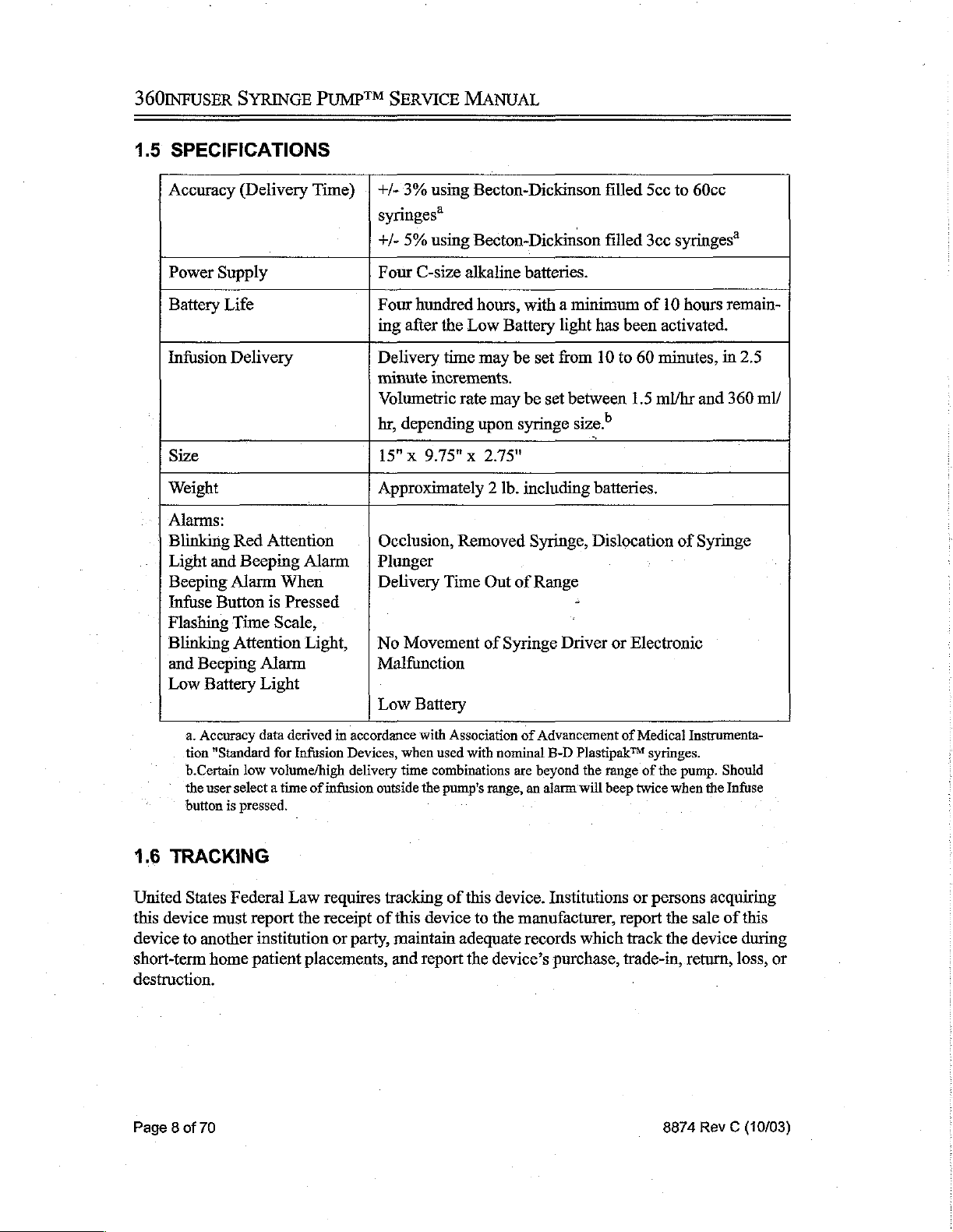
1.5
SPECIFICATIONS
Accuracy
Power
Battery
Infusion
Size
Weight
Alarms:
Blinking
Light
Beeping
Infuse
Flashing
Blinking Attention
and
Low
Supply
Life
Delivery
Red
and
Alarm
Button
Time
Beeping
Battery
a.
Accuracy
tion
"Standard
b.Certain low
the
user
select a time
button
is
SYRINGE
(Delivery
Attention
Beeping
When
is
Pressed
Scale,
Alarm
Light
data
derived
for
Infusion
volume/high
pressed.
PUMP™
Time) | +/-
Alarm | Plunger
Light, | No
in
of
infusion
SERVICE
3%
syringes*
+/-
5%
Four
C-size
Four
hundred
ing
after
Delivery
minute
Volumetric
hr,
depending
15"x
9.75" x 2.75"
Approximately 2 Ib.
Occlusion,
Delivery
Movement
Malfunction
Low
accordance
Devices,
delivery
Battery
with
when
time
outside
the
MANUAL
using
Becton-Dickinson
using
Becton-Dickinson
alkaline
hours,
the
Low
Battery
time
may
be
increments.
rate
may
upon
syringe
Removed
Time
Out
of
of
Syringe
Association
used
with
nominal
combinations
pump's
are
range,
filled
filled
batteries.
with a minimum
light
has
set
from
10
to
be
set
between
size?
|
including
Syringe,
Range
of
Advancement
beyond
an
alarm
batteries.
Dislocation
+
‘
Driver
B-D Plastipak™
the
will
or
of
range
beep
5cc
to
60cc
3cc
syringes*
of
10
hours
been
activated.
60
minutes,
1.5
ml/hr
of
Syringe
Electronic
Medical
twice
Instrumenta-
syringes.
of
the
pump.
when
remain-
in
and
Should
the
Infuse
2.5
360
ml/
1.6
TRACKING
United
this
device
short-term
destruction.
Page 8 of
States
device
to
another
70
Federal
must
home
Law
requires
report
the
receipt
institution
patient
or
placements,
tracking
of
this
device
party,
maintain adequate
and
report
of
this
device.
to
the
the
device’s
Institutions
manufacturer,
records
which
purchase,
or
persons
report
the
track
the
trade-in,
8874
acquiring
sale
of
this
device
return,
during
loss,
Rev C (10/03)
or
Page 15
1.7
SERVICE
Ifthe
pump
manual,
and
fails
to
the
cause
&
PERFORMANCE
respond
to
cannot
the
operating
be
determined,
INFORMATION
or
troubleshooting
discontinue
using
INTRODUCTION
procedures
the
pump.
listed
in
this
Service
contacting:
Product
With
a
and
occurred,
Should
(preferably
manufacturer
while
Authorization
contact
Number.
and
product
compiaints
each
complaint,
description
volume,
they
of
the
and
it
be
necessary
in
are
Customer
the
difficulty
type
any
other
the
original
cannot
in
transit.
to
return
Service
performance
B.
1601
Carrollton,
Attn.:
(800)
(800)
may
be sent
please
include
experienced,
of
I.V.
fluid
information
to
return
packing),
assume
any
products
at
the
information
Braun
Medical
Wallace
Texas
Drive,
Manager
627-PUMP
627-7867
to
the
Manager
the
serial
information
in
use,
the
alarms
which
the
pump
and
responsibility
must
above
to
ship
be
received
phone
might
the
it
may
be
obtained
Inc.
Suite
150
75006
of
Service
of
Quality
number
or
lot
regarding
displayed
aid
in
the
manufacturer,
prepaid
for
number
to
the
loss
or
from
B.Braun
for a Returned
from
the
Assurance
number
at
investigation
the
the
at
of
time
time
carefully
above
address.
damage
・
to
returned
prior
Goods
to
manufacturer
the
above
address.
the
product
setting,
the
of
pack
shipment.
syringe
difficulty
the
complaint.
the
pump
The
instruments
Authorization
by
involved,
size
Please
With
each
question
*
opump's
* - description
+ © initial
*
type
*
amount
noticed
・
alarms
*
catalog
8874
Rev C (10/03)
or
serial
of
volume
of
fluid
of
time
displayed
and
lot
complaint,
number
the
difficulty
to
be
infused
between
at
the
time
number
of
please
the
include
experienced
start
the
difficulty
the
set(s)
of
the
infusion
in
use.
the:
occurred
and
the
time
the
difficulty
was
Page 9 of
70
Page 16
360INFUSER
SYRINGE
PUMP™
SERVICE
MANUAL
.
This
page
intentionally
left
blank.
Page
10
of
70
8874
Rev C (10/03)
Page 17

RECEIVING
PROCEDURE
CHAPTER
RECEIVING
IN
*
*
*
+
2.14
INTRODUCTION
211
If
been
appropriate
All
acceptable
cause
Notices
the
product
replaced
final
bodily
is
partially
or
calibrations
performance
for
patient
harm
2.0
PROCEDURE
THIS
CHAPTER
How
to
properly
How
to
perform a receiving
What
procedures
Ofthe
repaired,
testing
use
and
system
or
completely
the
and/or
with
will
void
unit
tests
of
an
YOU
receive
to
follow
displays
disassembled,
must
undergo
as
outlined
the
360infuser
exception
all
warranties.
WILL
in a pump.
inspection.
when
and
alarms
and
in
must
for
syringe
LEARN:
checking
and
their
or a component
pass
all
this
manual
be
performed
sterility
in a pump.
indications
or
performance
prior
to
use
with a syringe
only.
Failure
assembly
checks
for
and
patient
that
to
do
so
has
the
care.
is
may
2.1.2
Upon
chandise
extent
agent
notify
an
age,
indicating
Carrollton,
must
portation
2.1.3
Items
Service
ordered
Damaged
receipt,
should
of
the
of
the
the
transportation
inspection
and
file a claim
the
Texas
be
accompanied
company
Goods
ordered
is
notified
in
error
Goods
count and
not
damage
transportation
inspect
be
accepted.
or
loss
company.
company
report
rendered.
with
the
item
and
quantity
office
(see
by a delivery
has
properly
Received
or
shipped
(see
must
in
in
Section
be
returned
your
Identify
noted
on
immediately,
B.Braun
carrier,
damaged
Section
noted
Error
error
may
1.7),
freight
freight
before
any
the
customer's copy
If
damage
will
be
providing
or
not
1.7),
and
receipt
such
be
and
or
damage
returned
the
products
prepaid
the
items
that
is
discovered
and request
happy
to
your
request
received
received
an
within
inspection
or
loss.
to
the
are
by.
the
carrier
are
damaged
of
that
departs.
the
delivery
after
receipt
inspection
issue a credit
and
the
are
promptly
ten
days.
report
upon
warehouse
returned
provided
within
customer.
Damaged
or
lost,
and
document
of
shipment,
be
for
the
loss
carrier's
freight
forwarded
The
claim request
which
Customer
14
days.
mer-
have
made
or
to
the
trans-
Items
the
by
an
and
dam-
bill
the
8874
Rev C (10/03)
Page
11
of
70
Page 18
360INFUSER
SYRINGE
PUMP™
SERVICE
MANUAL
Credit
*
»
+
*
Certain
*
*
Except
tomer.
2.1.4
B.Braun
cause
acts
tial
tials,
will
Proper
Products
Products
Merchandise
products
Products
Products
in
Late
beyond
of
God,
shortages,
equipment,
be
issued
authorization
are
in
the
are
current
has
are
which
whose
the
case
of a B.
Shipments
shall
be
excused
its
or
its
war,
acts
fire,
flood,
or
transportation.
for
ail
returns
has
been
original
inventory
been
shipped
not
eligible
have been
labels
or
seals
Braun
from
suppliers'
of
government,
strike,
for
goods
obtained
undamaged
items,
for
and
billed
return
and
used.
have
been
error,
items
any
delay,
or
subcontractors’
acts
labor
trouble,
received
(refer
to
Section
cases,
suitable
to
the
customer
for
credit.
These
tampered
must
be
returned
or
impossibility
control,
of
purchase
sabotage
in
error
provided:
1.7),
for
immediate
by
are:
with
or
removed.
freight
of
performance,
including,
priorities
or
delay
or
in
resale,
B.
Braun.
prepaid
due
but
not
allocations,
obtaining
by
the
to
any
limited
raw
mate-
labor,
mate-
cus-
to:
2.1.5
When
Expedited
expedited
specified
added
to
2.2
RECEIVING
Each
360infuser
There
is,
however,
therefore,
receipt
by
the
your
Checks."
1.
Before
obvious
open
to
return
the
opening
the
place
damaged
company,
Carefully
case
the
Shipments
transportation,
by
the
customer,
the
invoice.
INSPECTION
is
factory
the
following
(customer)
the
damage.
container
responsibility
equipment
whether
remove
pump
ever
tested
possibility
inspection
policy,
shipping
If
damage
until a representative
for
or
the
pump
has
to
specialized
an
additional
and
of
in-transit
is
refer
container,
is
present,
shipping
to
the
not
the
company
from
be
shipped
services,
charge
inspected
to
prior
damage
recommended.
to
Chapter
inspect
notify
of
damage
manufacturer
the
shipping
for
3.0
it
the
the
shipping
after
unless
is
responsible
carton.
repair.
or
alternate
cover
the
premium
to
its
final
packaging
which
If
carefully
freight carrier
may
functional
"Simulated
to
assure
company
the
shipping
container
specifically
for
the
Retain
the
transportation
expense
and
or
may
not
be
testing
is
required
Use
and
Performance
the
absence
immediately,
is
present.
is
opened).
authorized
repair.
packaging
modes
will
be
shipment.
obvious;
upon
of
and
wait
(It
is
difficult
Do
to
do
so
materials
in
are
to
not
by
Page
12
of
70
8874
Rev C (10/03)
Page 19

RECEIVING
PROCEDURE
Carefully
of
shipping
Make
5.
Make
Check
2.3
OPERATING
Refer
to
1.
Press
displaying
completed,
Move
away
Insert
positioned
Once
Pusher
rim
inspect
damage
sure
the
sure
there
the
pole
the
360infuser
the
360infuser
all
the
the
Pusher
from
the
the
filied
in
again,
Block
is
positioned
the
pusher
are
no
clamp
PROCEDURE
Operator's
24
LCD
time
scale
Block
unit,
then
syringe
the
clamp
pressing
down
until
between
pump
block
visible
for
ease
Power
time
is
to
the
slide
in
the
notch.
on
the
it
the
for
dents,
of
the
dents,
of
Guide
On
bars
automatically
top
the
Syringe
Pusher
catches
plunger
scratches,
pump
tears
operation.
for
button.
and
all 4 LEDs,
of
the
The
unit
entire
Clamp,
Block
the
rim
lock
slides
up
or
scratches
complete
system
set
at
by
pulling
Pusher
Block
making
and
pulling
of
the
notch
missing
and
down
on
operation
will
perform
one
at a time.
30
minutes.
the
upwards.
sure
the
syringe
and
the
parts,
or
any
easily.
the
pump
instructions.
an
When
Plunger
the
rim
Plunger
plunger.
syringe
driver
other
obvious
membrane
electronic
this
test
Lock
as
far
of
the
syringe
Lock
back,
Make
sure
notch.
signs
panel.
self-test,
has
been
as
possible
barrel
is
slide
the
the
plunger
Set
the
delivery
indicates
If
an
upon
+
the
audible
the
pump
For
units
bell
symbol
Tone
button
determine
Infusion
light
stays
end
of
begun,
button,
*
Forunits
button,
bell
symbol's
not.
+
For
units
Alarm
activation.
time
using
established
tone
at
the
version):
with
the
in
the
(these
if
the
audible
Complete
on
as
long
the
infusion
press
the
Stop
and
finally,
with
the
press
the
Infusion
appearance
with
no
bell
Tone
Off
button
the
Increase
delivery
end
of
the
Infusion
LCD,
versions
Complete
press
alarm
Tone
(On)
as
the
has
been
Infusion
press
the
bell
symbol
Complete
in
symbol
to
disable
or
Decrease
time
throughout
infusion
Tone
the
Infusion
operate
button
activated.
Infuse
identically)
had
been
button
and,
is
pressed,
button,
button
in
the
display and
To
then
Tone
the
display
in
the
display
all
audible
buttons.
the
is
desired,
On
or
Infusion
Complete
before
selected
ifa
after the
beep
then
activate
press
(to
continue
the
(On)
button.
indicates
and
the
alarms
The
infusion.
perform
the
Complete
Tone
On
the
infusion
infusion
sounds
the
this
the
whether
Alarm
and
audible
alarm
Infusion
the
infusion).
Infusion
The
presence
this
Tone
for
one
top
bar
following
Tone
or
Infusion
begins.
begins,
the
Infusion
alarm
after the
Complete
Complete
or
alarm
Off
minute
after
on
the
screen
(depending
without
Complete
To
press
Complete
signalling
infusion
Tone
(On)
Tone
(On)
absence
is
activated
button,
press
their
the
the
has
of
or
the
the
the
8874
Rev C (10/03)
Page
13
of
70
Page 20
360INFUSER SYRINGE
7.
To
begin
infusion, press
light
and
the
top
bar
8.
9.
10.
down,
The
An
Stop
without
To
press
ing
Infusion
infusion
Infusion
as,
’
reset
the
the
one
bar
below
Complete
may
button.
altering
the
CAUTION:
Attention
to
press
the
needed,
the
remove
delivery
appropriate
Infuse
button.
be
If
LED
PUMP™
the
for
the
the
top
light
stopped
The
Stop
original
during
the
flashes.
Stop
Infusion
the
time
after the
Increase
SERVICE
Infuse
time
that
bar
will
will
blink
at
any
Infusion
time
setting.
infusion
To
syringe
or
Decrease
MANUAL
button.
has
During
been
disappear
when
time
by
pressing
button
an
occlusion
deactivate
button,
infusion
from
unlock
the
has
Time
set
will
every
the
infusion
allows
the
pusher.
begun,
Set
the
infusion,
both
flash.
2.5
minutes.
has
either
the
the
operator
alarm
occlusion
the
syringe
press
button.
the
green
As
been
completed.
Power
to
appears,
alarm,
head
the
Stop
Restart
Infuse
the
time
Off
button
resume
the red
you
and,
Infusion
the
infusion
indicator
scale
or
the
have
if
button,
by
counts
the
infusion
then
press-
Page
14
of
70
This
space
intentionaily
left
blank.
8874
Rev C (10/03)
Page 21
2.4
DISPLAYS
AND
ALARMS
RECEIVING
PROCEDURE
Blinking
Blinking
Beeping
Yellow
Green
Indicates
an
Red
Indicates
plunger
Driver
an
has
stops,
Alarm
Indicates
properly
Low
the
placed.
Battery
Attention
Indicates a minimum
activated).
Red
Infusion
Signals
Infusion
Provides
Complete
the
Complete
an
Infuse
Light
infusion
occlusion
been
moved
and
the
When
set
delivery
Light
Infuse
Complete
end
of
the
Tone
audible
is
in
progress.
Light
and
in
the
up
or
Stop
Infusion
Button
time
of
10
hours
the
infusion
Light
infusion.
signal
at
Beeping
IV
set,
down
is
out
the
end
the
syringe
during
button
is
Pressed
of
range
remains
in
progress
of
the
Alarm
has
an
infusion.
must
be
for
the
in
the
battery
and replace
infusion.
been
removed,
In
pressed
syringe
(after
the
a
|
or
these
instances,
to
deactivate
size,
or
the
light
batteries.
the
the
has
syringe
the
Syringe
the
alarm.
syringe
first
is
not
been
Flashing
Indicates
units,
was
infusing.
Time
no
this
Scale,
movement
may
indicate
The
Blinking
of
the
that
unit
should
This
Attention
Syringe
the
syringe
be
sent
to
space
intentionally
Light,
Driver
and
or
was
removed
Biomedical
Beeping
an
electronic
from
Engineering.
left
blank.
Alarm
malfunction.
the
clamp
while
In
certain
the
unit
8874
Rev C (10/03)
Page
15
of
70
Page 22

360INFUSER
SYRINGE
PUMP™
SERVICE
MANUAL
This
page
intentionally
left
blank.
|
Page
16
of
70
8874
Rev C (10/03)
Page 23
SIMULATED
USE
AND
PERFORMANCE
CHECKS
CHAPTER
SIMULATED
3.1
INSPECTION
The
following
unit's
case.
diagnostic
3.1.1
*。 . Stopwatch
*
Pressure
*
Syringes
*
B.Braun
«
Three
inspection
This
procedure
procedure
Equipment
least 1 second).
meter
(Becton
Cat.
way
3.0
USE
IN
THIS
CHAPTER
*
What
equipment
Performance
+
How
to
PROCEDURE
procedure
may
and
at
the
Required
(the
longest
(0-50
Dickinson
No
V6512
stopcock
AND
Checks.
perform
permits
be
used
completion
test
will
psig
minimum
Plastipak™
Extension
with
luer
PERFORMANCE
YOU
WILL
is
required
the
Simulated
testing
for
periodic
of
every
be
approximately 1 hour.
range,
Set (60
fittings.
LEARN:
to
perform
Use
of
the
inspection.
repair.
with
3cc, Sec,
inch
the
Simulated
and
Performance
360infuser
It
should
Record
0.1
10cc,
microbore
all
Resolution
psig
resolution).
20cc, 30cc,
tubing
CHECKS
Use
Checks.
without
be
data
for
and
set).
and
opening
performed
this
should
the
section.
be
60cc).
as
at
a
3.1.2
1.
Install
2.
Press
3.
Press
4.
Press
+
*
8874
Rev C (10/03)
Unit
batteries.
Power
Power
*
Beep
*
Each
minutes.
*
Each
*
The
*
On
bell
Infuse
Observe
Unit does
Initialization
Do
not
Off
button.
On
button.
is
activated
segment
LED
LCD
bar
some
units,
symbol,
button
double
not
once.
of
LCD
flashes
graph
the
instructions
with
beep.
infuse.
Test
piace a syringe
Observe
bar
in
order
indicates
bell
graph
from
symbol
the
30
appears
pertaining
no
syringe
in
the
following
is
activated
bottom
to
minutes.
within
to
its
in
place.
clamp.
sequence
except
top.
the
ZERO
function
appear
of
for
one
events:
indicating
bar.
(If
on
the
the
unit
rear
ZERO
has
case
Page
the
label.)
17
of
70
Page 24
360INFUSER
SYRINGE
PUMP™
SERVICE
MANUAL
3.1.3
1.
Place
Infusion
*
*
.
Press
+
*
*
3.
Press
*
3.1.4
^
See
Figure
Infusion
an
Observe
On
some
Infuse
Observe
Observe
LCD
Power
Observe
Occlusion
Complete
unfilled
Complete
single
units,
button.
single
green
display
Off
button.
all
displays
Test
10cc
Tone
beep.
observe
beep.
Infuse
activated.
ATTENTION: A new
3-1
for
pressure
Tone
syringe
(On)
bell
LED
and
lights
syringe
meter
Test
in
the
clamp,
button
(if
symbol
blinking.
turn
should
set
up
description.
set
the
time
applicable).
disappears
off.
be
used
in
for
to
ZERO
each
+
30
minutes,
bar.
test.
and
press
the
1.
Place a 3cc
pusher
Do
not
.
Press
.
Set
the
Connect
Extension
.
Advance
the
3-way
meter
.
Close
.
Press
.
When
syringe
block.
push
down
Power
the
Infuse button.
On
delivery
the
pressure
Set
(Cat.
the
pusher
valve
(to
zero
vent
the
system
*
the
Attention
*
the
alarm
*
the
motor
button.
time
(all
the
system).
valve
detects
beeps,
stops
filled
with
on
the
for
10
meter
No
V6512).
toward
air
is
out
and
zero-out
an
LED
and
running.
3.0
cc
syringe
using
minutes.
to
the
syringe
the
clamp
of
the
system)
the
occlusion:
flashes,
of
water
into
position
pusher
block; a loose
through a 3-way
until 2 or 3 drops
and
zero
relative
meter.
in
the
stopcock
of
water
pressure
clamp
mounting
and a B.Braun
appear
is
block
and
is
desired.
at
the
end
applied
to
of
the
Page
18
of
70
8874
Rev C (10/03)
Page 25

SIMULATED
USE
AND
PERFORMANCE
CHECKS
9.
10.
11.
These
Press
ing
reads
events
Power
Repeat
Attention
between
Press
Power
ol
ии
щен
1-9
ЕГЕРЕЕЕЕ!
should
Off
button.
using
LED,
5.0
Off
occur
60cc
syringe
multiple
and
button
when
beeps,
13.2
psig.
and
disconnect
the
pressure
filled
with
and
60
cc
unit
shutdown)
the
unit
reading
of
water.
from
the
Syringe
is
between
The
should
test
20.0
and
occlusion
occur
apparatus.
alarms
when
46.8
(blink-
the
meter
psig.
OOo
Figure
3-1:Occlusion
<
O
J]
Test,
——
———
Pressure
V6512
Three-Way
Microbore
Transducer
Transducer
Pressure
Meter
Stopcock
Electrical
Meter
Setup
Tubing
Cord
8874
Rev C (10/03)
Page
19
of
70
Page 26

360INFUSER
SYRINGE
PUMP™
SERVICE
MANUAL
3.1.5
Time
Test
3.1.5.1
1.
Insert
clamp.
2.
Press
>
Set
Observe
decrease.
Set
P
Press
MH
Observe
NO
At
Complete
and
part
8.
Press
3.1.5.2
High
Speed
an
empty
Power
delivery
the
the
stopwatch
Infuse
flashing
the
moment
alarm)
10
minutes
of
the
syringe
Power
Low
Speed
60
cc
On
button.
interval
LCD
button
to
bar
to
zero.
and
green
when
the
stopwatch
18
seconds.
tip
Off
button.
syringe
10
minutes
graph
decrease
start
the
LED
the
syringe
as
an
indicator
with
plunger
by
stopwatch
and
downward
bottoms
should
Look
pressing
with one
read
for
the
of
the
extended
at
the
motion
out
between 9 minutes
stopper
syringe
Time
beep
same
(do not
pressing
bottoming
to
60
Set
Down
for
every
time.
of
plunger.
wait
cc
against
into
the
syringe
button.
incremental
for
an
Infusion
42
seconds
the
angled
out.
1.
Insert a new,
clamp.
2.
Press
3.
Set
delivery
*
Observe
increase.
4.
Set
the
5.
Press
6.
Observe
7.
At
the
Complete
and
61
part of
8.
Press
Power
Infuse
On
intervai
the
stopwatch
button
the
flashing
moment
alarm)
minutes
the
syringe
Power
Off
empty
button.
LCD
to
when
the
48
tip
button.
5cc
syringe
to
60
minutes
bar
graph
zero.
and
start
green
LED
the
syringe
stopwatch
seconds.
as
an
indicator
with
by
increase
the
stopwatch
and
bottoms
should
Look
for
plunger
pressing
one
extended
beep
at
the
downward
out
read
between
the
stopper
of
the
syringe
Time
for
every
same
motion
(do
not
pressing
bottoming
to 5 cc
Set
Up
incremental
time.
of
plunger.
wait
58
minutes
into
the
button.
for
an
Infusion
12
against
the
out.
syringe
seconds
angled
Page
20
of
70
8874
Rev C (10/03)
Page 27

Serial
Number
Tested
Dept./Location
Date
Test
Unit
Infusion
Occlusion - 3
Occlusion - 60
High
Low
By
Initialization
Complete
Speed
Speed
(time
(time
SIMULATED
Tone
сс
ce
test)
test)
Data
mins
mins
Sheet
Pass
USE AND
for
Testing
psi
psi
secs
(9min,42secs
secs
(58min,12secs
PERFORMANCE
360infuser
Fail
(20.0
to
46.8
psi)
(5.0
to
13.2
psi)
to
10min,18secs)
to
61min,48secs)
CHECKS
Comments:
8874
Rev C (10/03)
Page
21
of
70
Page 28

360INFUSER
SYRINGE
PUMP™
This
SERVICE
page
intentionally
MANUAL
left
blank.
Page
22
of
70
8874
Rev C (10/03)
Page 29

CLEANING
&
DISINFECTING
CHAPTER
CLEANING
WW
i
}
Clean
the
pump
following
Once
lint-free
with a soft,
Please
further
recommended
*
Household
+ © Isopropyl
*
Warm
the
infusion
cloth
refer
information.
ZEN
WARNING:
Sy
cleaning.
&
NN
Ml)
Én
)
with a swab
Alcohol
Soapy
pump
to
remove
lint-free
to
the
hospital's
4.0
DISINFECTING
IN
THIS
CHAPTER
+
Recommended
or
soft,
solutions:
Bleach
Water
is
all
cloth.
To
avoid
and
90%
cleaned,
wipe
remaining
housekeeping,
electrical
YOU
cleaning
lint-free
Water
the
cloth
entire
WILL
solutions
LEARN:
and
dampened
pump
twice with
cleaner/disinfectant.
central
shock,
service,
turn
the
procedures.
(not
saturated)
fresh
Thoroughly
or
infection
pump
off
before
with
water
dry
the
control
department
any
of
the
using a soft,
instrument
for
Ge.
CAUTION:
2
autoclave
|
¿Py
CAUTION:
‘©
solutions
abrasive
“ip,
CAUTION:
ペン
Autoclaving
8874
Rev C (10/03)
To
avoid
mechanical
or
immerse
To
avoid
containing
cleaners
Sterilization
is
not
the
mechanical
glutaraldehyde,
on
the
of
recommended.
or
electronic
pump
in
any
damage,
instrument.
the
pump
using
damage,
fluids
or
DO
NOT
ammonium
ethylene
DO
cleaning
use
acetone,
chlorides
oxide (EtO)
NOT
steam
solutions.
or
gas
or
Page
23
of
70
Page 30

360INFUSER
©
SYRINGE
CAUTION:
Do
PUMP™
not
clean
SERVICE
the
pump
MANUAL
using
high-pressure
devices.
This
space
intentionally
left
blank.
Page
24
of
70
8874
Rev C (10/03)
Page 31

TROUBLESHOOTING
CHAPTER
5.0
TROUBLESHOOTING
IN
THIS
CHAPTER
*
The
main
assemblies
*
This
chapter
configuration
designed
has
been
for
replacement
provides
of
to
aid the
identified,
General
detailed
the
360infuser.
bioengineer
Chapter 6 of
and
repair.
troubleshooting
information
The
General
in
pinpointing
this
manual
YOU
WILL
of
the
procedures.
regarding
Troubleshooting
problems
provides
LEARN:
pump
the
information
and
their
location.
mechanical
Guide
and
their
sources.
on
and
electrical
detailed
ordering
in
Once
and
Section
the
5.1
problem
procedures
is
8874.
Rev C (10/03)
Page
25
of
70
Page 32

360INFUSER
SYRINGE
PUMP™
SERVICE
MANUAL
=
5
à
$ a
2
|
o 2
= =
을
È
o
m
3
8
©
B
a
=
8
=
&
g
a
동
5
B E E
¿sz
=
$
E
=
8
о
5
> 5
>
2
E
2
2
=
= 3
5
2
ош
&
Ec
$
5
을
3
o
Assembly
Block
Pusher
@
>
6
©
№
N
N
N
à
>
~
N
NÍ
NN
AN
>
5
Е
È
<
= κ
e
Page
2
3
=
S
8
26
of
70
o
x
8
>
Е
5
<
2
9
a
5 5
5
o
Figure
\
\
à
5-1:
Exploded
View
8 a
a
3
>
E
6
=
5
©
8874
Rev C (10/03)
Page 33

TROUBLESHOOTING
Pin
on
PC
Board
Pin
14
to
Pin
25
Pin
30
Pin
31
Pin
32
Pin
33
Pin2
Pin3
[Pin
35
Pin
36
Pin
37
Pin
38
¡Pin6
Pin
7
Pin
27
Pin
28
Wire
Color
Ribbon
Cable
White/Blue
White/Yellow
White/Green
White/Red
Red
Black
_¡Green
Yellow
Orange
Brown
Red
Red/Black
Orange
White
KEY
|
Connector
Jt
J2
i
"JE
JB
Controls
Switch
Panel
Clamp
Block
Power
Resistor
Strip
Meter
Alarm
Figure
5-2:
PC
Board
8874
Rev C (10/03)
Page
27
of
70
Page 34

360INFUSER
SYRINGE
PUMP™
SERVICE
MANUAL
Figure
5-3:
Electrical
Schematic
Page
28
of
70
8874
Rev C (10/03)
Page 35

360
Infusion
Component
Controller
Side
install
Insulated
(From
to
Pin
TROUBLESHOOTING
cp
Connector - Back
Jumper
Pin
Marked 0 of
32
of
U5)
Wire
LCD
as
Shown
Connector
Side
Figure
Revision - Compoment
Infusion
Controller
LCD
Side
Path
Copper
Cut
in
Location
Shown
Side
of
Figure
5-4:
Board
LCD
install
Wire
Infusion
LCD
Controller
Insulated
in
Location
5-5:
Infusion
Controller,
Jumper
as
Shown
Controller,
Component
LCD
Side
Side
From
Pin 35
of
Socket
8874
Rev C (10/03)
Page
29
of
70
Page 36

360INFUSER
5.1
GENERAL
Problem
On
key
LCD
indicators
sound
Not
ali
One
or
function
LCD
timer
to
30
minutes
Displays
LCD
time
accordance
Tone
does
infusion
No
tone
is
pressed
Multiple
is
pressed
Alarm
starting
sounds
is
pressed,
LCD
indicators
more
LED
does
are
erratic
display
with
not
is
sounded
tones
an
infusion
SYRINGE
TROUBLESHOOTING
light,
not
at
end
Time
sound
sound
within a few
PUMP™
but
nothing
but
tones
light
indicators
automatically
of
system
does
not
move
Set
keys
at
the
end
when
START
when
START
happens
do
do not
check.
in
of
key
seconds
SERVICE
not | +
set
MANUAL
GUIDE
Possible
*
・
*
*
*
*
Causes
Check
Check
Check
position
Check
Check
Check
LCD
shifted
LCD
driver
replacement
Check
Check
Check
batteries
membrane
membrane
on
PC
buzzer
voltage
transistor
(U5)
LED
LED
driver
microprocessor
(U8)
Check
placement
(US)
Check
LCD
Check
Determine
Check
Check
key
of
Check
Check
Check
Check
Check
Check
potentiometer
Adjust
shifted
board
(On)
was
(Off)
activated,
seating
or
membrane
properly
if
INFUSION
activated
membrane
membrane
syringe
syringe
wiring
syringe
occlusion
plunger
clamp
assembly
switch
switch
board
level
at
(Q8)
or
LCD
(U7)
and
seating
.
of
the
microprocessor
poor
contact
switch
or
INFUSION
switch
switch
placement
clamp
switch
from
clamp
for
presence
circuit
driver
wiper
strip
is
in
correct
connector
require
(U10)
and
of
at
the
is
plugged
COMPLETE
switch
of
occlusion
and
wiper
and
contact
EPROM
EPROM
(U10)
connector
into
Tone
TONE
with
Page
30
of
70
8874
Rev C (10/03)
Page 37

Infusion
but
after
Infusion
All
sounds
infusion
Upon
minutes
Attention
occlusion
starts
alarm
sounds
approximately
time
indicators
immediately
power
with
alarm
present.
and
functions
and
all
15
minutes
delivery
blink
up
LCD
continuous
is
and
upon
locks
sounds
normally
displays
inaccurate
alarm
starting
alarm
and
tone
at
60
there
flash,
is
*
*
*
・
If
Technical
+
an
Contact
7867.
*
*
*
*
no
The
mechanical
properly.
Check
Check
Conduct
unable
Condition
Check
motor
plunger
with
drive
to
properly
Services
electronics
B.Braun
placement
(U8)
Check
Replace
The
was
seating
crystal
syringe
in
progress.
TROUBLESHOOTING
drive
and
drive
driver
train
alignment
is
the
failure.
was
procedure.
align,
800-627-7867.
result
Technical
and
of
the
(Y1)
removed
is
not
functioning
train
and
its
engagement
contact
of
Services
seating
microprocessor
if
necessary
an
internal
of
while
B.Braun
800-627-
EPROM
(U10)
an
infusion
8874
Rev C (10/03)
Page
31
of
70
Page 38

360INFUSER
SYRINGE
PUMP™
This
SERVICE
page
intentionally
MANUAL
left
blank.
Page
32
of
70
8874
Rev C (10/03)
Page 39

REMOVAL
AND
INSTALLATION
PROCEDURES
CHAPTER
REMOVAL
\
72
uu
SS
SS
\K
MAİ»
In
order
be
opened. The
Test
Procedures
that
is
opened.
3,
should
See
the
following pages
versions
»
H
2)
4
to
replace
batteries
and
In
be
performed
ATTENTION:
the
studs
of
the
360infuser™.
any
addition,
6.0
AND
IN
THIS
*
What
*
How
What
*
What
component
should
the
Occlusion
on
every
It
is
or
case
for
INSTALLATION
CHAPTER
tools/equipment
to
repair
Subassembly
tests
are
or
be
the
test
unit.
very
important
halves
information
YOU
and/or
and
required
assembly
removed
Adjustment
procedures
when
on
WILL
are
required
replace
to
how
the
Repair
after
each
(except
prior
to
Procedure
pertaining
avoid
closing
to
order
LEARN:
to
repair
major
Service
repair.
for
the
opening
must
to
delivery
pinching
the
unit.
the
correct
PROCEDURES
the
pump.
subassemblies
Kits
are
instruction
the
pump
be
performed
time,
any
wires
parts
of
available
label),
case.
detailed
between
for
the
pump.
the
unit
The
Alignment
on
every
in
the
different
must
unit
Chapter
To
Order:
Call
your
revision,
For
information
627-PUMP
8874
Rev C (10/03)
authorized
and
guantity
(1-800-627-7867).
B.Braun
information
regarding
Customer
spare
available
parts
and
Service representative.
as
well
as a Purchase
repair,
call
B.Braun
Have
Order
Technical
the
Catalog
number.
Service
Number,
at
1-800-
Page
33
of
70
Page 40

360INFUSER
6.1
SUB
Cat
#
FZ8850
FZ8851
FZ8852
FZ8853
FZ8854
FZ8856
FZ8861
FZ8862
FZ8863
FZ8864
FZ8865
FZ8867
FZ8868
FZ8871
FZ8872
8874
FZ8877
FZ8898
FZ8899
8900
FZ401073
FZ0044
SYRINGE
ASSEMBLY
PUMP™
AND
SERVICE
REPAIR
Description
Front
Case
Pusher
Display
Curtains
Rear Case
Motor
Microprocessor
LCD
Wired
Battery
Split
Assembly
Block
Driver
Assembly
with
Gear
Battery
Door
Ring
Buzzer
Clamp
PC
Block
Board
Rev2
Crystal
Service
EPROM
Pole
Rear
Operation Guide
Home
Kit,
Manual
Rev
Clamp
Label
Position
Boot
Installation
Rev
MANUAL
SERVICE
Terminal
7
7
Alignment
KITS
Spacer
i
(Too!)
Page
34
of
70
8874
Rev C (10/03)
Page 41

6.2
ASSEMBLY
REMOVAL
REPAIR
AND
INSTRUCTIONS
INSTALLATION
PROCEDURES
6.2.1
Front
6.2.1.1
6.2.1.2
Case
Assembly
Materials
* 1 Front
* 2 Curtains
* 1 Battery
* 3 No 6 Case
Procedure
1
The
PN
HP
Case
Door
Remove
case
procedure. A heat
Remove
Remove
With
Remove:
‧
* © the
Remove
the
label
should
for
the
batteries.
the
the
pump
the
buzzer
power
the
Assembly
with
Positive
Screws
instruction
be
label
removed
replacement
gun
is
3.back
chassis
case
lying
on
connector
connector
by
disconnecting:
Battery
from
cleanly
label
that will
useful
screws.
its
face,
at
J6,
at
J3.
Terminal
the
and
in
removing
remove
and
back
case.
conipletely
be
applied
the
the
back
7
in
at
the
label.
case.
order
to
prepare
completion
of
the
this
8874
Rev C (10/03)
+
*
*
*
Set
the
Remove
Set
the
Discard
Attach
8.
Reinstall
9.
10.
Reinstali
11.
Reconnect
+
the
motor
connector
the
switch
the
clamp
the
resistor
chassis
the 2 screws
PC
the
the
motor connector
block
aside.
board
damaged
curtain
the
PC
the
chassis.
the:
panel
strip
aside.
to
board
at
J5,
connector
connector
connector
that
hold
front
case.
the
new
front
into
the
at
J5
with
at
J1,
at
J2,
at
J4.
the
PC
case.
front
the
red
and
board
case.
lead
in
place.
towards
motor,
Page
35
of
70
Page 42

360INFUSER
©
#
SYRINGE
*
*
*
12.
Reconnect:
+
»
13.
Proceed
14.
Attach
tioning.
Caution:
provided
attached
PUMP™
the
switch
the
clamp
the
resistor
the
buzzer
the
power
connections
to
Chapter 7 for
the
back
When
and
to
reattaching
take
the
J1
SERVICE
panel
connector
block
connector
strip
connector
connector
connector
towards
case
while
the
care
not
to
connector
MANUAL
at
JI,
at
J2,
and
at
J4.
at
J6,
and
at
J3,
with
the
motor.
Calibration
holding
back
bend
or
any
procedures.
the
case,
or
crimp
other
orange
battery
use
the
door
the
ribbon
wires.
and
three
red
in
its
cable
leads
of
channel
sorews
both
for
posi-
15.
16.
Replace
Proceed
batteries
to
(ordered
Chapter 3 for
separately).
Simulated
Use
and
Performance
Checks.
Page
36
of
70
-
8874
Rev C (10/03)
Page 43

REMOVAL
AND
INSTALLATION
PROCEDURES
8874
Rev C (10/03)
Figure
6-1:
Back
Case
Page
37
of
70
Page 44

360INFUSER
SYRINGE
PUMP™
SERVICE
MANUAL
6.2.2
Split
6.2.2.1
6.2.2.2
Ring
and
Materiais
* 1 Split
Procedure
1.
N
Ring
Remove
The
label
case
for
procedure. A
Remove
Remove
With
the
Aaa
Remove
の
Place
the
コロ
Proceed
の
Attach
ing.
the
Retainer
with
Ring
the
instruction
should
the
be
replacement
heat
gun
batteries.
the 3 back
pump
lying
any
broken
ring
retainer
to
Chapter 6 for
back
case
Retainer
label
removed
label
is
useful
case
screws.
on
its
pieces
between
Calibration
while
holding
from
cleanly
that
in
face,
of
the
the 2 case
the
back
and
completely
will
be
removing
remove
ring
the
retainer
procedures.
the
battery
case.
applied
the
label.
back
from
halves.
door
in
at
the
case.
inside
in
its
order
to
prepare
completion
the
pump.
channel
for
the
of
this
position-
E
>/
Caution:
provided
attached
Attach a new
9.
10.
Replace
11.
Proceed
When
and
take
to
the
batteries.
to
reattaching
care
not
J1
connector
instruction
Chapter 3 for
the
back
to
bend
or
any
label
(order
Simulated
case,
or
other
crimp
wires.
use
the
separately).
Use
and
the
three
ribbon
Performance
cable
screws
Checks.
Page
38
of
70
8874
Rev C (10/03)
Page 45

REMOVAL
AND
INSTALLATION
PROCEDURES
6.2.3
Curtains
6.2.3.1
6.2.3.2
Materials
* 2 Curtains
Procedure
1.
Remove
The
case
the
label
should
for the
procedure. A heat
Remove
Remove
PN
With
P
Replace
M
Replace
A,
Proceed
Attach
PN
ing.
batteries.
the 3 back
the
pump
the
the
to
the
instruction
be
label
removed
replacement
gun
is
case
lying
on
curtain
curtain
on
on
the
the
Chapter 7 for
case
halves
while
from
the
cleanly
label
that
will
useful
in
removing
screws.
its
face,
remove
back
case
front case.
Calibration
holding
back
case.
and
completely
be
applied
the
label.
the
back
case.
and
set
the
back
procedures.
battery
door
at
in
in
order
the
case
its
channel
to
prepare
completion
aside.
for
position-
of
the
this
“is,
re
wy
Caution:
provided
attached
Attach a new
9.
10.
Replace
11.
Proceed
When
and
take
to
the
batteries.
to
reattaching
care
not
J1
connector
instruction
Chapter 3 for
the
back
to
bend
or
any
label
(order
Simulated
case,
or
crimp
other
wires.
separately).
Use
and
use
the
the
ribbon
Performance
three
cable
screws
Checks.
8874
Rev C (10/03)
Page
39
of
70
Page 46

360INFUSER
SYRINGE
PUMP™
SERVICE
MANUAL
6.2.4
Rear
6.2.4.1
6.2.4.2
Case
Assembly
Materials
* 1
Rear
case
Assembly
* 2 Curtains
* 3 No 6 Case
Procedure
1.
Remove
The
case
procedure. A heat
Remove
EN
Remove
With
WP
Ifthe
A
new
Reconnect:
the
label
should
for
the
batteries.
the 3 back
the
pump
pump
buzzer
Screws
instruction
be
label
removed
replacement
gun
is
case
lying
on
has a buzzer
is
premounted
from
cleanly and
label
that will
useful
screws.
its
face,
mounted
on
the
in
removing
remove
on
the
the
new
back
case.
completely
be
applied
the
and
discard
chassis,
back
case.
+
in
‘at
the
label.
the
remove
order
to
prepare
completion
damaged
it
and
discard.
back
of
the
this
case.
am,
2
*.
*
Proceed
8.
Attach
tioning.
Caution:
provided
attached
9.
Attach a new
10.
Replace
11.
Proceed
the
buzzer
the
power
connections
to
Chapter 7 for
the
case
When
and
to
reattaching
take
the
J1
batteries.
to
Chapter 3 for
connector
connector
towards
halves
while
the
care
not
to
connector
instruction
label
at
J6,
and
at
J3,
with
the
motor.
Calibration
holding
back
bend
or
any
Simulated
case,
or
crimp
other
(order
Use
procedures.
the
separately)./
orange
battery
use
the
the
wires.
and
Performance
and
red
door
three
ribbon
leads
in
its
screws
cable
Checks.
of
both
channel
for
posi-
Page
40
of
70
8874
Rev C (10/03)
Page 47

6.2.5
Battery
REMOVAL
Door
AND
INSTALLATION
PROCEDURES
6.2.5.1
6.2.5.2
©
Caution:
Sy
provided
attached
Materials
*
Baitery
Procedure
1.
Remove
The
case
procedure. A heat
Remove
Remove
YN
Proceed
Attach
vB
tioning.
Door
the
label
for
the
batteries.
the 3 back
to
the
When
and
take
to
the
should
Chapter 7 for
case
reattaching
J1
with
Positive
instruction
be
replacement
halves
care
label
removed
label
gun
is
case
screws.
while
the
not
to
connector
Battery
Terminal
from
the
cleanly
and
that will
useful
Calibration
holding
back
bend
or
any
in
removing
procedures.
the
case, use
or
crimp
other
back
case.
completely
be
applied
the
s
battery
the
the
wires.
at
the
label.
door
three
ribbon
in
order
to
completion
in
its
channel
screws
cable
prepare
of
this
for
posi-
the
6.
Attach a new
7.
Replace
8.
Proceed
instruction
batteries.
to
Chapter 3 for
label
(order
Simulated
separately).
Use
and
Performance
Checks.
8874
Rev
(10/03)
C
Page
41
of
70
Page 48

360INFUSER
SYRINGE
PUMP™
SERVICE
MANUAL
6.2.6
Wired
6.2.6.1
6.2.6.2
Battery
Terminal
Materials
*
Wired
Procedure
1.
battery
Remove
The
label
case
for
the
should
the
replacement
procedure. A heat
Remove
Remove
With
ры
Remove:
»
*
Remove
If
necessary,
the
tact.
batteries.
the 3 back
the
pump
the
buzzer
the
power
the
battery
terminal
Treminal
instruction
be
removed
gun
label
is
case
lying
on
connector
connector
damaged
trim
back
and
battery
case
from
cleanly and
label
that
useful
screws.
its
face,
at
J6,
at
J3.
terminal
so
there
the
back
the
back
will
be
in
removing
remove
and
and
is
clearance
case.
Do
case.
completely
applied
the
at
label.
-
the
back
case.
discard.
between
notcrimp
in
order
the
completion
the
the
terminal's
to
prepare
of
positive
metal
the
this
end
con-
of
©
ペン
Slide
back
Pinch
it
onto
10.
Reconnect:
*
‧
11.
Proceed
12.
Attach
tioning.
Caution:
provided
attached
the
positive end
case.
the
metal
the
post
the
buzzer
the
power
connections
to
Chapter 7 for
the
case
When
and
to
reattaching
take care
the
J1
of
the
contact
portion
connector
connector
halves
on
of
towards
while
the
not
to
connector
battery
the
the
at
at
J3,
motor.
Calibration
bend
or
terminal
negative
battery
J6,
and
with
holding
back
case, use
or
crimp
any
other
compartment
the
procedures.
the
onto
end
of
orange
battery
the
the
wires.
its
mounting
the
battery
spring.
and
red
door
three
ribbon
terminal
leads
in
its
screws
cable
location
of
both
channel
and
for
on
the
slide
posi-
Page
42
of
70
8874
Rev C (10/03)
Page 49

REMOVAL
13.
Attach a new
14.
Replace
15.
Proceed
instruction
batteries.
to
Chapter 3 for
AND
label
INSTALLATION
(order
Simulated
separately).
Use
and
Performance
PROCEDURES
Checks.
6.2.7
Instruction
6.2.7.1
6.2.7.2
Label
Materials
*
Instruction
Label
Procedure
1.
Remove
The
case
the
label
for
the
should
procedure. A heat
2.
Remove
3.
Attach
4.
Replace
batteries.
the
new
Batteries.
instruction
be
replacement
instruction
label
removed
label
gun
is
from
cleanly
that
useful
label.
the
back
and
will
in
removing
case.
completely
be
applied
the
in
at
the
label.
order
to
prepare
completion
of
the
this
8874
Rev C (10/03)
This
space
intentionally
left
blank.
Page
43
of
70
Page 50

360INFUSER
SYRINGE
PUMP™
SERVICE
MANUAL
6.2.8
PC
6.2.8.1
6.2.8.2
Board
Materials
+ 1
PC
Board
+ 2 Support
per
Cushions
Procedure
1.
Remove
The
case
procedure. A heat
Remove
Remove
With
BRN
Remove:
A
+
*
6.
Remove
the
label
should
for the
batteries.
the 3 back
the
pump
the
buzzer
the
power
the
replacement
Revision
per
Revision
instruction
be
label
removed
label
gun
is
case
screws.
lying
on
its
connector
connector
chassis
by:
from
cleanly and
that
useful
face,
at
J6,
at
J3.
in
and
the
back
will
be
removing
remove
case.
completely
applied
the
the
back
at
label.
case.
in
order
the
completion
to
prepare
of
the
this
*
*
+ © the
Set
7.
Remove
Set the
8.
Discard
9.
Install
10.
Reconnect:
+
*
*
11.
Reconnect:
+
* © the
12.
Proceed
disconnecting
the
switch
clamp
the
chassis
front
the
the
the
the
the
aside.
the 2 screws
case
the
damaged
new
PC
motor
connector
switch
resistor
buzzer
power
connections
to
Chapter 7 for
the
motor
panel
connector
block
connector
that
aside.
PC
board.
board
into
panel
connector
strip
connector
connector
connector
towards
Calibration
connector
hold
the
the
at
J5
with
at
J6,
at
J3,
with
motor.
at
JI,
at
J2,
and
PC
board
front
case.
the
red
at
J1,
the
at
J4.
and
the
procedures.
at
J5,
the
resistor
in
Reinstall
lead
clamp
orange
place
towards
block
and
red
strip
connector
the
chassis.
motor,
connector
leads
of
at
J2,
both
at
J4.
and
Page
44
of
70
8874
Rev C (10/03)
Page 51

REMOVAL
13.
©
SA
Attach
tioning.
CAUTION:
provided
attached
14.
Attach a new
15.
Repiace
16.
Proceed
the
When
and
take
to
the
batteries.
to
back
case
reattaching
care
J1
connector
instruction
Chapter 3 for
while
not
AND
to
INSTALLATION
holding
the
back
bend
or
or
any
other
label
(order
Simulated
the
battery
case, use
crimp
the
wires.
separately).
Use
and
Performance
door
in
the
three
ribbon
cable
PROCEDURES
its
channel
screws
Checks.
for
posi-
6.2.9
EPROM
ATTENTION:
EPROMs.
6.2.9.1
6.2.9.2
For
Materials
+
Programmed
Procedure:
1.
Remove
The
case
procedure. A heat
Remove
the
labei
should
for the
batteries.
op
Remove
With
pop
a
Remove:
the 3 back
the
pump
all
old
revisions,
EPROM
instruction
per
be
removed
replacement
gun
is
case
lying
on
B.Braun
Revision
label
from
cleanly
label
that
useful
screws.
its
face,
the
and
will
in
removing
remove
~
should
í
back
case.
completely
be
applied
the
the
back
remove
in
at
the
label.
case.
the
obsolete
order
to
prepare
completion
of
the
this
8874
Rev C (10/03)
6.
+
the
*
the
Remove
+
disconnecting
*
the
»
the
*
the
buzzer
power
the
switch
clamp
resistor
connector
connector
chassis
panel
block
strip
at
at
by:
the
motor
connector
connector
connector
J6,
and
J3.
connector
at
J1,
at
J2,
at
J4.
at
and
J5,
Page
45
of
70
Page 52

360INFUSER
SYRINGE
Set
the
7.
Carefully
8.
Install
on
the
not
bend
9.
Reinstall
10.
Reconnect:
+
+
*
*
Reconnect:
11.
ㆍ
*
12.
Proceed
PUMP™
chassis
the
EPROM
the
the
the
the
the
the
connections
aside.
remove
new
EPROM,
and
the
EPROM's
the
chassis.
motor
connector
switch
clamp
resistor
buzzer
power
to
panel
block
strip
connector
connector
Chapter 7 for
SERVICE
the
EPROM.
making
the
orientation
pins.
connector
connector
connector
towards
Calibration
MANUAL
at
J5
with
at
J6,
at
J3,
with
motor.
sure
the
indicator
the
at
J1,
at
J2,
and
at
J4,
and
the
procedures.
orientation
marking
red
lead
towards
orange
and
is
correct
on
the
motor,
red
leads
(note
PC
of
the
notch
board).
both
Do
13.
.
CAUTION:
provided
attached
14.
15.
16.
Attach
back
When
and
take
to
the
J1
Attach a new
Replace
Proceed
batteries.
to
Chapter 3 for
case
while
holding
reattaching
care
not
to
connector
instruction
the
battery
the
back
case,
bend
or
or
any
other
label
(order
Simulated
door
use
crimp
the
wires.
separately).
Use
and
Performance
in
its
channel
the
three
ribbon
screws
cable
Checks.
for
positioning.
Page
46
of
70
8874
Rev C (10/03)
Page 53

REMOVAL
AND
INSTALLATION
PROCEDURES
6.2.10
Microprocessor
6.2.10.1
6.2.10.2
Materials
*
Microprocessor
Procedure:
1.
Remove
The
case
the
label
should
for
the
procedure. A heat
Remove
Remove
EŞ MR
Pp
With
인
Remove:
*
*
6.
Carefully
7.
Install
batteries.
the 3 back
the
pump
the
buzzer
and
the
remove
the
new
instruction
be
label
removed
replacement
gun
is
case
screws.
lying
on
its
connector
power
connector
the
microprocessor.
microprocessor.
from
cleanly and
label
that
useful
face,
at
J6,
at
the
back
wili
in
removing
remove
13.
case.
completely
be
applied
the
the
back
in
at
the
label.
case.
order
to
prepare
completion
of
the
this
“es,
2
Make
and
the
microprocessor's
8.
Reconnect:
,
+
*
9.
Proceed
10.
Attach
tioning.
CAUTION:
provided
attached
11.
12.
and
to
Attach a new
Proceed
sure
the
orientation
orientation
the
buzzer
the
power
connections
to
the
When
take
the
connector
connector
Chapter 7 for
back
reattaching
care
J1
connector
instruction
to
Chapter 3 for
indicator
pins.
towards
case
while
not
is
correct
marking
at
J6,
and
at
J3,
with
motor.
Calibration
holding
the
back
case,
to
bend
or
or
any
other
label
(order
Simulated
(note
the
notch
on
the
PC
the
orange
procedures.
the
battery
crimp
wires.
use
the
door
the
ribbon
separately)
Use
and
Performance
on
the
board).
and
red
in
its
three
cable
and
replace
microprocessor
Do
not
bend
the
leads
of
both
channel
for
posi-
screws
batteries.
Checks.
8874
Rev C (10/03)
Page
47
of
70
Page 54

360INFUSER SYRINGE
PUMP™
SERVICE
MANUAL
6.2.11
LCD
6.2.11.1
6.2.11.2
Materials
・
1LCD
* 2 Support
Cushions
Procedure:
1.
Remove
The
case
procedure. A heat
Remove
.
Remove
た の
With
ゆい
Remove:
‧
+
6.
Remove
the
label
should
for
the
batteries.
the 3 back
the
pump
the
buzzer
and
the
the
replacement
instruction
be
lying
label
removed
gun
is
case
on
connector
power
chassis
connector
by:
from
cleanly and
label
that
useful
screws.
its
face,
at
J6,
at
the
back
will
in
removing
remove
J3.
case.
completely
be
applied
the
the
back
。
in
at
the
label.
case.
order
to
prepare
completion
of
the
this
ATTENTION:
connector.
Set the
7.
Set
8.
This
9.
10.
Solder
next
*
‘disconnecting
*
the
switch
*
the
clamp
*
the
resistor
chassis
Remove
Remove
the 2 screws
the
front
the
operation
Slide
the
damaged
Some
Install
to
the
new
the
the
panel
block
strip
aside.
case
aside.
LCD
support
facilitates
LCD
devices
new
LCD
LCD
into
"0"
and
the
motor
connector
connector
connector
that
hold
cushions
removal
straight
may
require
and
support
place
aligning
hole
marked
connector
at
Jl,
at
J2,
and
at
J4.
the
PC
board
from
of
the
back
out of
to
cushions.
the
"BP"
at
5;
in
place.
the
PC
LCD.
its
desolder
board
between
next
to
board
socket
34 pins
the
"60".
and
discard.
and
discard.
of
the
hole
LCD
marked
"BP"
Page
48
of
70
8874
Rev C (10/03)
Page 55

REMOVAL
11.
Reinstall
12.
Reinstall
13.
Reconnect:
Reconnect:
14,
15.
Proceed
16.
Attach
the
PC
board
the
chassis.
the
motor
the
switch
the
clamp
the
resistor
the
buzzer
the
power
connector
panel
block
strip
connector
connector
connections
to
Chapter 7 for
the
back
case
AND
into
at
connector
connector
connector
towards
Calibration
while
INSTALLATION
the
front
case.
J5
with
the
at
J1,
at
J2,
and
at
J4.
at
J6,
and
at
J3,
with
the
motor.
procedures.
holding
the
-
red
lead
orange
battery
towards
and
red
door
in
PROCEDURES
motor,
leads
of
both
its
channel
for
posi-
tioning.
©
Sus
CAUTION:
provided
attached
When
and
to
the
reattaching
take
care
J1
connector
not
the
to
bend
or
any
back
or
case,
crimp
other
use
the
wifes.
the
three
ribbon
screws
cable
17.
Attach a new
18.
Proceed
instruction
to
Chapter 3 for
label
(order
Simulated
separately) and replace
Use
and
Performance
Checks.
batteries.
8874
Rev C (10/03)
Page
49
of
70
Page 56

360INFUSER
SYRINGE
PUMP™
SERVICE
MANUAL
6.2.12
LCD
6.2.12.1
6.2.12.2
Display
Driver
Materials
* 1 LCD
* 2 Support
Display
Cushions
Procedure:
Remove
1.
The
case
the
label
should
for the
replacement
procedure. A heat
Remove
Remove
With
Remove:
ABN
+
‧
Remove
batteries.
the 3 back
the
pump
the
buzzer
the
power
the
Driver
instruction
be
lying
connector
connector
chassis by
label
removed
gun
is
case
on
disconnecting:
from
cleanly and
label
that will
useful
screws.
its
face,
|
at
J6,
at
13.
the
back
be
in
removing
remove
and
case.
completely
applied
the
the
label.
back
at
case.
in
order
the
completion
to
prepare
of
the
this
*
the
*
the
*
the
‧
theresistor
Set
the
Remove
Set
the
Remove
This
operation
Slide
ATTENTION:
LCD
connector.
10.
Remove
11.
Install the
motor
switch
clamp
chassis
the 2 screws
front
case
the
LCD
the
LCD
Some
the
LCD
new
connector
panel
block
strip
at
connector
connector
connector
aside.
that
aside.
support
facilitates
straight
devices
US
back
may
driver
chip.
removal
from
J5,
at
JI,
at
J2,
at
J4.
hold
the
PC
cushions
of
out
of
its
require
PCB
and
board
from
the
the
LCD.
socket
to
desoider
by
desoldering
in
PC
and
place
board
set
34 pins
all
and
aside.
pins.
discard.
of
the
Page
50
of
70
8874
Rev C (10/03)
Page 57

REMOVAL
Make
sure
the
orientation
tation
ATTENTION:
there
the
damage
12.
Solder
Trim
is a jumper
display
13.
Clean
14.
Reinstall
15.
Reinstall
16.
Reinstall
17.
Reconnect:
indicator
the
US
U5
If
the
driver
the
LCD.
in
place.
lead
PC
wire
U5.
PC
the
LCD.
the
PC
the
chassis.
marking
to
0.020"
board
board.
board
from
AND
on
maximum
INSTALLATION
is
correct
the
PC
displays
pin O of
into
the
front
(note
board).
before
part
the
LCD
case.
the
notch
Bend
installing
number
connector
PROCEDURES
on
the
over
all
pins
LCD.
PD-7790,
to
pin
chip
and
so
ensure
32
as
of
the
not
orien-
to
©
2%
*
+
*
*
18.
Reconnect:
¢
*
19.
Proceed
20.
Attach
tioning.
CAUTION:
provided
attached
21.
Attach a new
22.
Replace
the
motor
the
switch
the
clamp
the
resistor
the
buzzer
the
power
connections
to
Chapter 7 for
the
back
When
and
to
reattaching
take
the
J1
care
connector
instruction
batteries.
connector
panei
connector
block
connector
strip
connector
connector
connector
towards
case
while
not
to
at
J5
with
the
at
J1,
at
J2,
at
J4.
at
J6,
and
at
J3,
with
motor.
Calibration
holding
the
bend
or
any
label
back
or
other
(order
the
case,
crimp
red
lead
towards
a
and“
the
orange
procedures.
battery
use
the
and
door
the
ribbon
wires.
separately)
red
leads
in
its
three
cable
motor,
of
channel
screws
both
for
posi-
8874
Rev
23.
Proceed
C.(10/03)
to
Chapter 3 for
Simulated
Use
and
Performance
Checks.
Page
51
of
70
Page 58

360INFUSER
SYRINGE
PUMP™
SERVICE
MANUAL
6.2.13
Crystal
6.2.13.1
6.2.13.2
Materials
+
Quartz
Procedure:
1.
Remove
The
label
case
for
Crystal
the
should
the
replacement
procedure. A heat
Remove
5.
Remove
With
a 5
Remove:
»
*
Remove
+
*
* — the
+
Set
the
the
the
the
the
the
the
chassis
batteries.
the 3 back
pump
buzzer
power
the
motor
switch
clamp
resistor
instruction
be
lying
connector
connector
chassis
connector
panel
block
strip
label
removed
gun
is
case
on
by
disconnecting:
connector
connector
connector
aside.
from
cleanly
label
that will
useful
screws.
its
face,
at
J6,
at
J3.
at
J5,
the
back
and
in
removing
remove
and
at
Ji,
at
J2,
and
at
14.
case.
completely
be
applied
the
the
back
4
in
at
the
label.
case.
order
to
prepare
completion
of
the
this
Page
52
of
10.
11.
12.
70
Remove
Set
the 2 screws
the
front
Desolder
Install
marked
The
board
the
on
crystal
and
place.
Reinstall
Reinstall
Reconnect:
*
the
motor
+
the
switch
case
the
damaged
new
the
should
the
the
PC
the
chassis.
aside.
crystal
PC
board.
lay
double
board
connector
panel
that
hold
crystal
with
flat
sided
with
tape
into
at
from
the
the
J5
with
connector
the
PC
board
PCB
and
body
of
the
the
terminals
facing
front case.
at
the
Jl,
the
red
in
place.
discard.
crystal
facing
outside
lead
of
towards
Clean
aligned
the
inside
the
PC
motor,
all
contact
within
8874
the
of
the
board.
Solder
Rev C (10/03)
holes.
area
PC
in
Page 59

REMOVAL
+
the
clamp
block
.
*
the
©
By
13.
Reconnect:
+
*
14.
Proceed
15.
Attach
tioning.
CAUTION:
provided
attached
16.
Attach a new
17,
Replace
resistor
the
buzzer
the
power
connections
to
the
When
and
take
to
the
batteries.
strip
connector
connector
Chapter 7 for
back
case
reattaching
care
J1
connector
instruction
AND
connector
connector
at
towards
Calibration
while
the
not
to
or
label
INSTALLATION
at
32,
and
at
J4.
at
Jó,
and
J3,
with
the
motor.
procedures.
holding
bend
any
back
or
other
(order
the
case,
crimp
separately).
orange
battery
use
thé
door
the
ribbon
wires.
and
three
PROCEDURES
red
leads
of
both
in
its
channel
screws
cable
for
posi-
18.
Proceed
to
Chapter 3 for
Simulated
Use
and
Performance
Checks.
8874
Rev C (10/03)
Page
53
of
70
Page 60

360INFUSER
SYRINGE
PUMP™
SERVICE
MANUAL
6.2.14
Buzzer
6.2.14.1
6.2.14.2
Materials
*
Buzzer
Procedure:
1.
Remove
The
case
the
label
for
the
should
replacement
procedure. A heat
Remove
ピロ
Remove
の
With
お
원
Remove:
*
* — the
6.
Carefully
7.
Install
batteries.
the 3 back
the
pump
the
buzzer
power
remove
the
new
instruction
be
lying
connector
connector
buzzer
label
removed
gun
is
case
on
the old
in
from
cleanly
label
that
useful
screws.
its
face,
at
J6,
at
J3.
buzzer
the
alternate
the
back
and
will
be
in
removing
remove
and
and
discard.
mounting
case.
completely
applied
the
the
label.
back
at
case.
located
in
order
the
completion
on
the
to
prepare
back
the
of
this
case.
#N
=
Use a flat-tipped
posts
and
8.
Reconnect:
*
the
*
the
connections,
9,
Proceed
10.
Attach
tioning.
CAUTION:
provided
attached
When
and
to
the
soldering
secure
buzzer
power
to
the
the
connector
connector
Chapter 7 for
back
case
reattaching
take care
J1
connector
buzzer.
towards
while
not
to
tool
or
equivalent
at
J6,
and
at
J3,
with
the
motor.
Calibration
holding
the
back
bend
or
any
procedures.
the
case, use
or
crimp
other
to
orange
battery
the
wires.
slightly
and
red
door
in
its
the
three
ribbon
cable
melt
leads
channel
screws
the
mounting
of
both
for
posi-
Page
54
of
70
8874
Rev C (10/03)
Page 61

VAN
ATTENTION:
chassis.
in
place,
location.
11.
12.
13.
In
discard
Cut
Attach a new
Replace
Proceed
REMOVAL
Some
this
units
case,
the
off
one
instruction
batteries.
to
Chapter 3 for
AND
may
have
remove
buzzer, and
of
the
the
new
label
Simulated
INSTALLATION
the
buzzer
screw
install
holding
the
buzzer's
(order
separately).
Use
mounted
the
new
mounting
and
Performance
damaged
buzzer
arms
PROCEDURES
to
the
buzzer
in
the
same
for
fit.
Checks.
8874
Rev C (10/03)
This
space
intentionally
left
blank.
Page
55
of
70
Page 62

360INFUSER
SYRINGE
PUMP™
SERVICE
MANUAL
6.2.15
Motor
6.2.15.1
6.2.15.2
With
Gear
Materials
* 1
Motor
* 1 Motor
* 3 Motor
・LOCTITE
Gear
Screws
242
Procedure:
1.
Remove
The
case
the
label
for
the
should
replacement
procedure. A heat
YN
wr
6.
Remove
Remove
With
Remove:
‧
* © the
Remove
batteries.
the 3 back
the
pump
the
buzzer
power
the
and
Set
Screw
instruction
lying
connector
connector
chassis
label
be
removed
gun
is
case
on
by
disconnecting:
from
cleanly
label
that will
useful
screws.
its
face,
at
J6,
at
J3.
the
back
and
be
in
removing
remove
and
case.
completely
applied
the
the
back
3
"
at
label.
case.
in
order
the
completion
to
prepare
of
the
this
/N
Page
56
of
*
the
*
the
*
the
*
the
Set
the
7.
Remove
8.
Remove
ATTENTION:
off
with a pair
9.
Install
notch
10.
Install
+
© Place a drop
70
motor
switch
clamp
resistor
chassis
the
old
the 3 motor
If
you can
of
pliers.
the
new
in
the
chassis.
the
new
connector
panel
connector
block
connector
strip
connector
aside.
motor
gear
screws
not
remove
motor,
motor
of
making
gear.
LOCTITE®
at
J5,
and
and
sure
at
J1,
at
J2,
and
at
J4.
discard.
discard
the
.035”
to
align
242
on
the
damaged
set
the
the
.035"
screw,
flat
of
the
set
motor.
pry the
motor
screw.
8874
gear
shaft
with
the
Rev C (10/03)
Page 63

REMOVAL
»
Slide
the
motor
with
the
flat
» o Tightenthe
11.
Reinstali
12,
Reconnect:
the
set
chassis.
gear
on
the
screw.
AND
onto
shaft
INSTALLATION
the
shaft
so
that
and
the
gear
is
aligned
the
PROCEDURES
.035"
set
screw
with
its
mating
lines
gear.
up
©
7
+ © the
»
*
‧
Reconnect:
13.
+
*
14.
Proceed
15.
Attach
CAUTION:
provided
to
the
J1
16.
Attach a new
17.
Replace
motor connector
the
switch
the
clamp
block
the
resistor
the
buzzer
the
power
connections
to
Chapter 7 for
back
case
When
and
reattaching
take
care
connector
instruction
batteries.
panel
connector
connector
strip
connector
connector
connector
towards
while
holding
not
to
or
any
other
at
J5
with
the
at
JI,
at
J2,
and
at
J4.
at
J6,
and
at
J3,
with
the
motor.
Calibration
the
the
back
bend
procedures.
battery
case, use
or
crimp
wires.
label
(order
separately).
red
lead
orange
door
the
-
towards
and
red
in
its
channel
the
three
ribbon
motor,
leads
screws
cable
of
both
for
positioning.
attached
8874
Rev C (10/03)
18.
Proceed
to
Chapter 3 for
This
space
Simulated
intentionally
Use
left
and
Performance
blank.
Checks.
Page
57
of
70
Page 64

360INFUSER
SYRINGE
PUMP™
SERVICE
MANUAL
6.2.16
Clamp
6.2.16.1
6.2.16.2
Block
Materials
»
Clamp
+
Clamp
Block
Block
Procedure:
1.
Remove
The
case
the
label
for
the
should
replacement
procedure. A heat
Remove
ゆい
Remove
With
お の
원
Remove:
*
*
Remove
batteries.
the 3 back
the
pump
the
buzzer
the
power
the
Assembly
Wiper
instruction
be
removed
gun
label
is
case
lying
on
connector
connector
chassis by
disconnecting:
from
cleanly
label
that
useful
screws.
its
face,
at
J6,
at
13.
the
back
and
will
be
in
removing
remove
and
case.
completely
applied
the
the
back
at
label.
case.
in
order
the
completion
to
prepare
of
the
this
*
the
*
the
+
the
*
the
Set
the
Loosen
motor
switch
clamp
resistor
case
front
the
set
connector
panel
block
strip
at
J5,
connector
connector
connector
aside.
screw ( 1/16")
This
space
intentionally
on
at
at
at
the
Jl,
J2,
J4.
clamp
and
left
collar.
blank.
Page
58
of
70
8874
Rev C (10/03)
Page 65

REMOVAL
1.
Remove
the
collar,
AND
spring,
and
INSTALLATION
washer,
along
with
PROCEDURES
the
clamp.
Wiper
Le
.
EM
.
Remove
Discard
Check
the
‘Figure
any
grease
damaged
bottom
6-2:
remaining
clamp.
rod
for
Clamp
burrs
on
by
the
Block
clamp
sliding
end
the
Syringe
of
the
collar
Compression
Clamp
chassis
along
the
rods.
rod.
Spring
Assembly
8874
Rev C (10/03)
・
・
5.
Attach
clamp.
A
flat-tipped
taken
6.
Slide
The
clamp
collar
7.
Position
the
set
ness.
Remove
Lightly
the
new
so
as
not
the
new
should
(in
that
the
clamp
screw
any
burrs
using a flat
relubricate
wiper
soldering
to
melt
clamp
order).
located
to
iron
these
onto
slide
on
See
so
that
on
the
the
the collar.
rods
after
clamp
on a low
nibs
the
rods.
easily.
Figure
it
is
flush
file.
filing.
by
melting
setting
is
recommended.
completely.
Slide on
8.
with
Locate
the
the
chassis
collar
the
plastic
washer,
end
to
remove
nibs
the
spring,
bracket
all
located
Care
should
and
and
spring
Page
on
the
be
the
tighten
loose-
59
of
70
Page 66

360INFUSER
© , CAUTION:
</
SYRINGE
Do
Compressing
8.
Reinstall
9.
Reconnect:
»
the
+
the
*
the
*
the
10.
Proceed
11,
Reconnect:
»
the
*
the
connections
12,
Attach
tioning.
PUMP™
not
compress
the
spring
the
chassis.
motor
connector
switch
clamp
panel
block
resistor
to
Chapter 7 for
buzzer
power
the
connector
connector
back
case
SERVICE
will
connector
connector
strip
connector
towards
while
MANUAL
the
spring
affect
at
J5
the
with
at
at
J2,
at
J4.
J1,
Calibration
at
J6,
and
at
J3,
with
motor.
holding
when
tightening
occlusion
the
red
lead
and
procedures.
the
orange
the
battery
the set
pressure
towards
and
red
leads
door
in
its
screw.
readings.
motor,
of
both
channel
for
posi-
fs
®/
CAUTION:
provided
to
the
J1
13.
Attach a new
14.
Replace
15.
Proceed
When
and
reattaching
take care
connector
instruction
batteries.
to
Chapter 3 for
This
or
not
any
space
the
back
case,
to
bend
or
crimp
other
wires.
label
(order
Simulated
Use
intentionally
use
the
the
ribbon
separately).
and
Performance
left
blank.
three
cable
screws
attached
Checks.
Page
60
of
70
8874
Rev C (10/03)
Page 67

REMOVAL
AND
INSTALLATION
PROCEDURES
6.2.17
Pusher
6.2.17.1
6.2.17.2
Block
Materials
+ 1 Pusher
¢ 1
Wiper
Block
Procedure:
1.
Remove
The
case
the
label
for
the
should
replacement
procedure. A heat
Remove
ο
Remove
sw
With
a
Remove:
+
+
Remove
batteries.
the 3 back
the
pump
the
buzzer
the
power
the
Assembly
instruction
lying
connector
connector
chassis
label
be
removed
gun
is
case
on
by
disconnecting: o .
from
cleanly
label
that
useful
screws.
its
face,
at
J6,
at
J3.
the
back
and
will
in
removing
remove
and
case.
completely
be
applied
the
the
back
in
at
the
label.
case.
order
to
prepare
completion
of
the
this
Set
9.
10.
+
the
*
the
*
the
*
the
Set
the
Loosen
Remove
the
Move
the
Loosen
the
resistor
upper
bracket
motor
switch
clamp
resistor
case
front
the
set
the
collar,
clamp
block
damaged
the 2 set
strip),
and
connector
panel
connector
block
connector
strip
connector
aside.
screw
on
spring,
aside.
pusher
screws
and
slide
out
of
at
J5,
the
clamp
and
block
that
the
the
pusher
at
at
at
washer,
to
hold
the
bottom
J1,
J2,
and
J4.
|
collar.
along
the
upper
bottom
guide
block
with
bracket
guide
rod
out
groove.
the
clamp
block.
end
(top
position).
rod
(the
one
about 2 inches
away
from
from
the
8874
Rev C (10/03)
|
Page
61
of
70
Page 68

360INFUSER
Lead
Screw
SYRINGE
PUMP™
SERVICE
MANUAL
Half-Nut
Pusher
Pusher
(optional)
Release
Button
の
の
et
7
|
Pointed
.
(e.g.
È
x
É
р
Implement
Scribe)
Pin
‘Pusher
Pusher
(optional)
Access
Release
Button
Hole
Page
62
of
70
11.
Replace
12.
Attach
A
flat-tipped
taken
13.
Pull
move
so
up
the
the
the
wiper
as
not
the
pusher
damaged
Figure
wiper
(facing
by
melting
soldering
to
melt
release
pusher
6-3:
Pusher
the
clamp).
the
plastic
iron on a low
these
nibs
completely.
to
keep
the
block
out
Block
nibs
setting
of
half
the
is
nut
chassis.
located
recommended.
away
on
the
from
pusher.
Care
lead
screw
8874
should
Rev C (10/03)
and
be
re-
Page 69

REMOVAL
14.
Position
¢
*
15.
Tighten 2 set
16.
Reinstall
17,
Reinstall
18.
Reconnect:
the
Pull
up
groove
Slide
block
the
the
pusher
the
half
to
the top
the
bottom
and
into
screws
clamp
chassis.
AND
block
with
nut
(use
guide
guide
the
hole
that
hold
block.
INSTALLATION
the
wiper
toward
the
rod.
rod
on
the
upper
pusher
through
release)
the
bracket.
bottom
guide
the
and
other
rod.
PROCEDURES
clamp
block.
hook
pusher
side
groove
of
block
the
pusher
ον
:>7
+ © the
‧
・
*
19.
Proceed
20.
Reconnect:
*
*
21.
Attach
tioning.
CAUTION:
provided
to
the
J1
22.
Attach a new
23.
Replace
motor
the
switch
the
clamp
the
resistor
to
Chapter 7 for
the
buzzer
the
power
connections
the
back
When
and
reattaching
take
care
connector
instruction
batteries.
connector
panel
connector
block
connector
strip
connector
connector
connector
towards
case
while
not
to
or
any
other
at
J5
with
the
at
J1,
at
J2,
at
J4.
Calibration
at
J6,
and
at
J3,
with
motor.
holding
the
bend
back
or
the
case,
crimp
wires.
label
(order
red
lead
towards
and
procedures.
the
orange
battery
a
use
the
and
door
the
ribbon
separately).
red
in
its
three
cable
motor,
leads
of
channel
screws
attached
both
for
posi-
8874
Rev C (10/03)
24,
Proceed
to
Chapter 3 for
Simulated
Use
and
Performance
Checks.
Page
63
of
70
Page 70

360INFUSER
SYRINGE
PUMP™
This
SERVICE
page
intentionally
MANUAL
left
blank.
Page
64
of
70
8874
Rev C (10/03)
Page 71

CALIBRATION
PROCEDURES
CHAPTER
7.0
CALIBRATION
IN
THIS
*
What
equipment
*
How
to
The
test
ensure
7.1
ALIGNMENT
7.1.1
*
» 0 to
‧
procedures
the
safety
Equipment
External
50
365
inch
detailed
and
Power
Amp
spacer
efficiency
TEST
Required
Supply,
Digital
PROCEDURES
CHAPTER
perform a mechanical
in
this
of
PROCEDURES
5.5 + .050
Voltmeter, 0 to
YOU
is
required
chapter
the
should
360infuser.
WILL
VDC
10.000
LEARN:
to
complete
inspection
be
performed
-
(Batteries
VDC
range
these
and
on
cannot
.001
checks.
adjustment
every
opened
be
used)
volts
resolution
of
the
pump.
unit
to
See
Figure
5-2
for
location
of
test
This
points.
space
intentionally
left
blank.
8874
Rev
C.(10/03)
Page
65
of
70
Page 72

360INFUSER
SYRINGE
PUMP™
SERVICE
MANUAL
7.1.2
1.
2.
3.
Initial
Unit
must
be
Determine
It
should
Connect a jumper
be
Set-up
opened.
that
all
connectors
snug,
but
not
between
JA
J2
Jé
Ji
jo
LES
except
tight.
R43
©
de
(U4
©
à
the
J3
side)
4
battery
and
connector
cathode
us
of
“
are
D10.
correctly
connected.
4.
Connect
5.
Turn
the
the
power
Power
supply
supply
Figure
(in
on.
This
space
7-1:
Jumper
Off
position)
intentionally
Location
between
left
Pin 2 (+)
blank.
and
Pin 3 (-).
Page
66
of
70
8874
Rev C (10/03)
Page 73

CALIBRATION
PROCEDURES
7.1.3
1,
Place
Advance
2.
Depress
3.
Check
Home
the
Power
voltage
Position
home
the
pusher
On
between
Alignment
position
until
button.
Pin
(.365
it
rests
35
inch)
against
and
Pin 3 and
spacer
the
between
spacer.
record
the
lower
It
should
value.
bracket
be
snug,
and
but
the
pusher.
not
tight.
4.
Refer
proper
sured.
5.
Connect
Adjust
6.
step
For
ing
to
the
Home
the
R45
until the
4.
example,
at
Pin
26
"Home
voltmeter
Position
Position
for a voltage
of
Voltage
between
reading
.621 + 0.003
Voltage
value
Pin
on
the
、
at
Pin
VDC.
Adjustment"
for
the
particular
26
and
Pin
Digital
35 of
3.00
See
Voltmeter
Data
table
Pin
3.
is
VDC, R 45
Sheet
7A.
(Data Sheet
35
voltage
equal
to
the
should
be
adjusted
3A)
to
that
value
select
was
mea-
selected
for.a
the
in
read-
8874
Rev C (10/03)
Page
67
of
70
Page 74

360INFUSER
Data
Sheet
7A
SYRINGE
PUMP™
SERVICE
MANUAL
Home
TP35
Voltage.
2.91
2.92
2.93
2.94
2.95
2.96
2.97
2.98
2.99
3.00
3.01
3.02
3.03
3.04
3.05
3.06
3.07
3.08
3.09
3.10
3.11
3.12
3.13
3.14
3.15
3.16
3.17
Position
Voltage
-
-
Adjustment
-
Table
Home
。
Position
o
Voltage
-602 + 0.003
-605 + 0.003
.607+0.003
-609 + 0.003
.611 + 0.003
.613 + 0.003
.615
+0.003
.617+0.003
.619+0.003
621+0.003
-623 + 0.003
.625+0.003
.627+0.003
.629+0.003
.631+0.003
.633 + 0.003
.635+0.003
.637 + 0.003
.640+0.003
.642+0.003
.644 + 0.003
.646 + 0.003
.648 + 0.003
-650 + 0.003
652
0.003
.654+
.656 + 0.003
0.003
Page
68
of
70
This
space
intentionally
left
blank.
8874
Rev C (10/03)
Page 75

CALIBRATION
PROCEDURES
7.1.4
1.
With
Pin 3 with
Check
7B.
2.
Adjust
above,
3.
Slide
4.
Complete
5.
Ifboth
Checks.
return
Occlusion
the
unit
open
the
Digital
that
the
R49
for
+.00/-.01V.
spring
the
tests
If
to
step
collar
Occlusion
pass,
the
pump
.
ATTENTION:
and
if
pressure
Adjustment
and
the
Voltmeter.
voltage
the
is
between
voltage
down
snug
Tests
continue
fails
If
pressure
readings
clamp
between
on
in
Chapter
on
and
either
test,
readings
are
lubricated,
the
tolerances
Pin
the
spring
29
measure
and
and
3.
complete
adjust
high
the
the
are
low
remove
the
0.207 V and
Pin 3 to
tighten
Simulated
tension
add
be
the
on
tension
tension
voltage
0.250
equal
set
screw.
Use
and
the
spring
to
the
from
the
between
V.
to
the
Performance
Pin
See
value
appropriately
spring
spring.
38
and
Data
Sheet
recorded
and
8874
Rev C (10/03)
This
space
intentionally
left
blank.
Page
69
of
70
Page 76

360INFUSER
Data
Sheet
Voltage
0.207
0.208
0.209
0.210
0.211 1.266
0.212
0.213
0.214
0.215
0.216
0.217
0.218
0.219
0.220
0.221
0.222
0.223
0.224
0.225
0.226
0.227
0.228
0.229
0.230
0.231 1.386
0.232
0.233
0.234
0.235
0.236
0.237
0.238
0.239
0.240
0.241
0.242
0.243
0.244
0.245
0.246
0.247
0.248
0.249
0.250
SYRINGE
7B
between
Pin
-
38
PUMP™
and
Pin
SERVICE
3
MANUAL
o
Voltage
>
.
X6
1.242
1.248
1.254
1.260
1.272
1.278
1.284
1.290
1.296
1.302
1.308
1.314
1.320
1.326
1.332
1.338
1.344
1.350
1.356
1.362
1.368
1.374
1.380
1.392
1.398
1.404
1.410
1.416
1.422
1.428
1434
1.440
1.446
1.452
1.458
1.466
1.470
1.476
1.482
1.488
1.494
1.500
Page
70
of
70
8874
Rev C (10/03)
Page 77

Page 78

B.
Braun
824
Bethlehem,
Medical
Twelfth
PA
Avenue
1-800-227-2862
www.bbraunusa.com
Inc.
18018
 Loading...