


Combi 80 Eco
Baxi Combi 80Eco
Gas Fired Wall Mounted Combination Boiler
Installation and
Servicing Instructions
Please leave these instructions with the user

2
Baxi UK Limited is one of the leading manufacturers
of domestic heating products in the UK.
Our first priority is to give a high quality service to our
customers. Quality is designed into every Baxi product
- products which fulfil the demands and needs of
customers, offering choice, efficiency and reliability.
To keep ahead of changing trends, we have made a
commitment to develop new ideas using the
latest technology - with the aim of continuing to make
the products that customers want to buy.
Everyone who works at Baxi has a commitment to
quality because we know that satisfied customers
mean continued success.
We hope you get a satisfactory service from Baxi. If
not, please let us know.
Natural Gas
Baxi Combi 80Eco
G.C.No47 075 05
Baxi is a BS-EN ISO 9001
Accredited Company
The boiler meets the requirements of Statutory Instrument
“ The Boiler (Efficiency) Regulations 1993 N
o
3083” and is
deemed to meet the requirements of Directive 92/42/EEC
on the energy efficiency requirements for new hot water
boilers fired with liquid or gaseous fuels:-
Type test for purpose of Regulation 5 certified by:
Notified Body 0051.
Product/Production certified by:
Notified Body 0051.
For GB/IE only.
3
1.0 Introduction 4
2.0 General Layout 5
3.0 Appliance Operation 6
4.0 Technical Data 7
5.0 Dimensions and Fixings 8
6.0 System Details 9
7.0 Site Requirements 12
8.0 Installation 17
9.0 Commissioning the Boiler 22
10.0 Completion 24
11.0 Servicing the Boiler 25
12.0 Changing Components 27
13.0 Illustrated Wiring Diagram 36
14.0 Fault Finding 37
15.0 Short Parts List 42
Section Page
Contents
Baxi UK Limited declare that no substances
harmful to health are contained in the
appliance or used during appliance
manufacture.
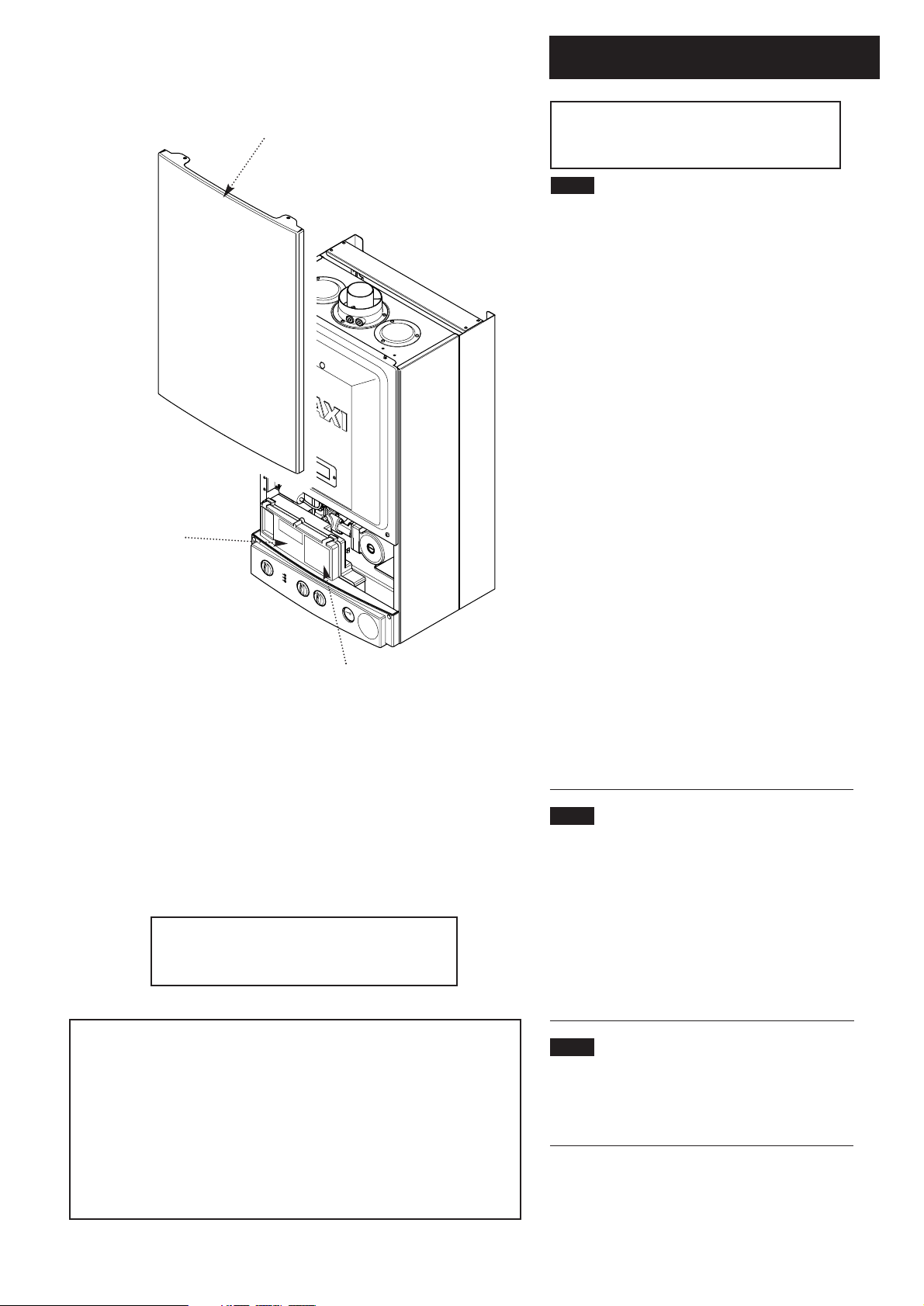
1.1 Description
1. The Baxi Combi 80Eco is a fully automatic gas
fired wall mounted combination boiler. It is room
sealed and fan assisted, and will serve central
heating and mains fed domestic hot water.
2. The boiler is set to give a maximum output of
24.0 kW.
3. It is designed for use on Natural Gas (G20) and
can be converted to use Propane or Butane.
4. The boiler is suitable for use only on fully pumped
sealed heating systems. Priority is given to
domestic hot water.
5. The boiler data badge gives details of the model,
serial number and Gas Council number and is
situated on the control box. It is visible when the
case front panel is removed (Fig. 1).
6. The boiler is intended to be installed in residential
/ commercial / light industrial E.M.C. environments
on a governed meter supply only.
7. The boiler must be installed with one of the
purpose designed flues such as the standard
horizontal flue kit, part no. 247719.
8. All systems must be thoroughly flushed and
treated with inhibitor (see section 6.2).
1.2 Installation
1. The appliance is suitable for installation only in G.B. and I.E.
and should be installed in accordance with the rules in force.
For Ireland install in accordance with I.S.813 “I
NSTALLATION OF
GAS APPLIANCES”. The installation must be carried out by a
CORGI Registered Installer or other competent person and be
in accordance with the relevant requirements of G
AS SAFETY
(Installation and Use) REGULATIONS, the BUILDING REGULATIONS
(Scotland) (Consolidation), the LOCAL BUILDING REGULATIONS,
the C
URRENT I.E.E. WIRING REGULATIONS and the bye laws of the
Local Water Undertaking. Where no specific instructions are
given, reference should be made to the relevant BRITISH
STANDARD CODES OF PRACTICE.
1.3 Optional Extras
Various flue extensions, bends, vertical flue kits,
control accessories etc. are available as optional
extras. These are detailed in a separate publication.
1.0 Introduction
4
Data Badge
Fig. 1
Control Box
Case Front Panel
“Benchmark” Log Book
As part of the industry-wide “Benchmark” initiative all Baxi boilers now
include an Installation, Commissioning and Service Record Log Book.
Please read the Log Book carefully and complete all sections relevant to
the appliance and installation. These include sections on the type of
controls employed, flushing the system, burner operating pressure etc.
The details of the Log Book will be required in the event of any warranty
work. Also, there is a section to be completed at each subsequent regular
service visit. The Log Book must be left with the user.
NOTE: This appliance must be installed in
accordance with the manufacturer’s instructions
and the regulations in force. Read the instructions
fully before installing or using the appliance.
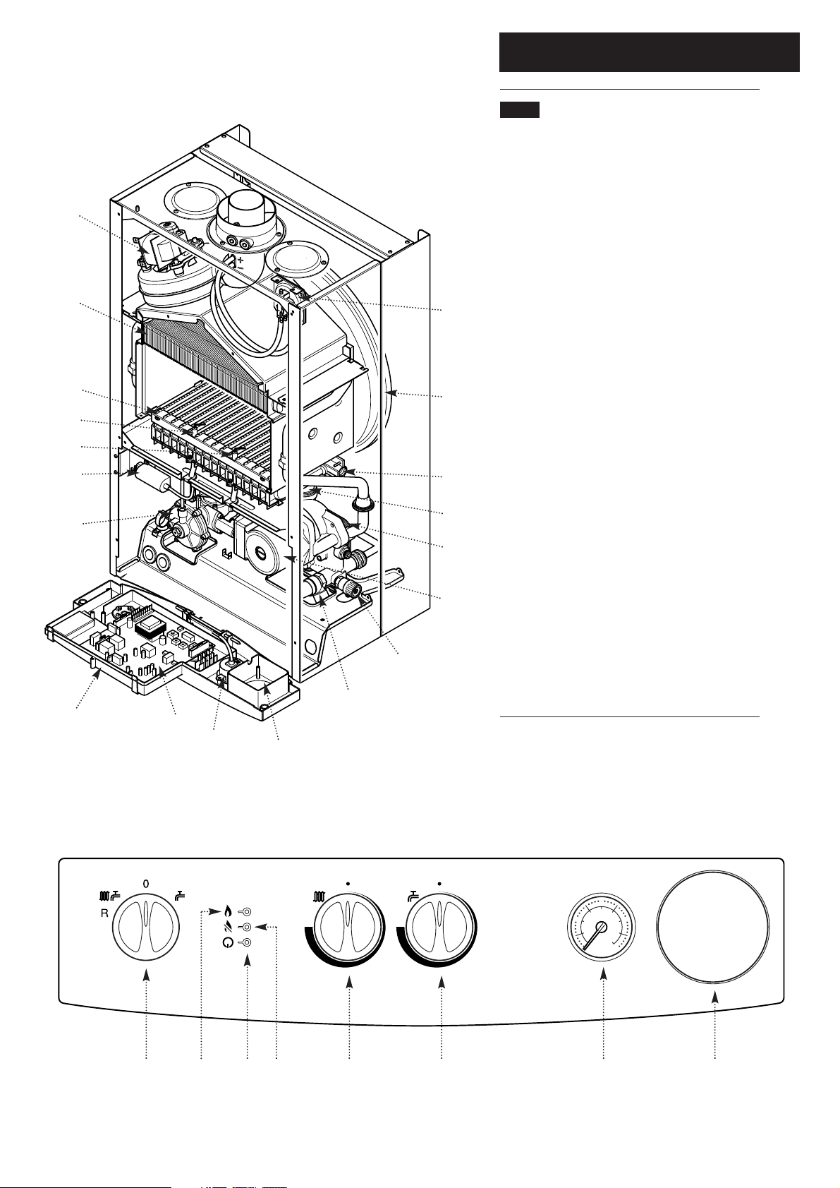
2.0 General Layout
5
2.1 Layout
1. Air Pressure Switch
2. Expansion Vessel
3. Burner Manifold
4. Automatic Air Vent
5. DHW Plate Heat Exchanger
6. Circulation Pump
7. Drain Off Point
8. Pressure Relief Valve
9. Optional Integral Timer Position
10. Central Heating System Pressure Gauge
11. Control PCB
12. Control Box
13. 3-Way Valve Assembly
14. Spark Generator
15. Flame Sensing Electrode
16. Spark Electrode
17. Burner
18. Primary Heat Exchanger
19. Fan Assembly
20. On / Off / Reset Selector Switch
21. Burner On Neon
22. Power On Neon
23. Flame Failure Neon
24. Central Heating Temperature Control
25. Hot Water Temperature Control
19
18
17
14
15
16
13
12
11
10
9
20 21 22 23 24 25 10 9
7
6
3
4
5
8
2
1
2
1
0
4
3
bar
Fig. 2
Fig. 3
3.0 Appliance Operation
6
NOTE: All delay timers mentioned in 3.1 and
3.2 are overridden by domestic hot water
demand.
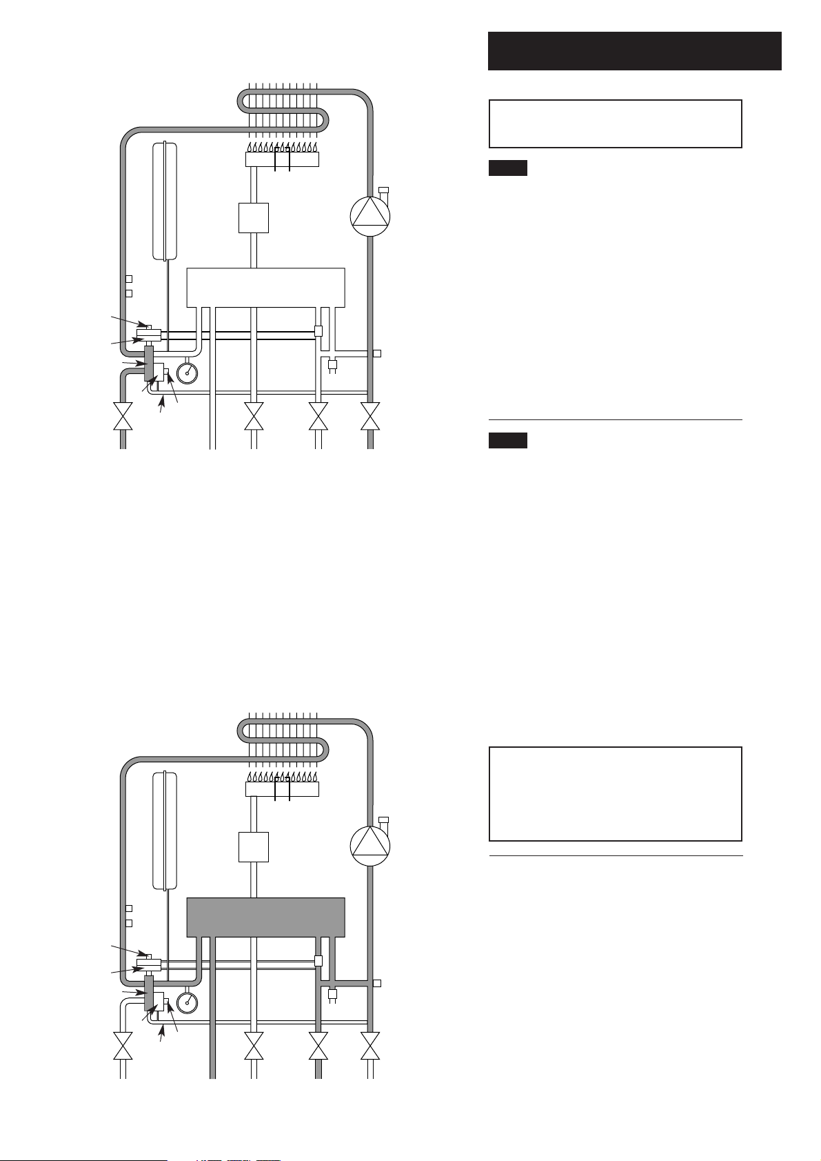
3.1 Central Heating Mode (Fig. 4)
1. With a demand for heating, the pump circulates
water through the primary circuit. At a predetermined flow rate the central heating flow
switch operates, initiating the ignition sequence.
2. The main burner ignites at low rate, then the
gas valve controls the gas rate to maintain the
heating temperature measured by the
temperature sensor.
3. When the flow temperature exceeds the setting
temperature, a 3 minute delay occurs before the
burner relights automatically (anti-cycling). The
pump continues to run during this period.
3.2 Domestic Hot Water Mode (Fig. 5)
1. Priority is given to the domestic hot water
supply. A demand at a tap or shower will override
any central heating requirement.
2. The flow of water will operate the DHW flow
switch which requests the 3 way valve to change
position. This will allow the pump to circulate the
primary water through the DHW plate heat
exchanger.
3. The burner will light automatically and the
temperature of the domestic hot water is
controlled by the temperature sensor.
4. When the domestic hot water demand ceases
the burner will extinguish and the diverter valve
will remain in the domestic hot water mode,
unless there is a demand for central heating.
IMPORTANT: When the selector switch is in
the ‘0’ (Off) position the electrical supply to the
boiler is isolated. The boiler will not operate
and the integral timer (if fitted) will require
resetting once the selector switch is turned to
either the DHW or CH position.
1
2
4
5 6
7
8
9
10
11
1213141516
17
18
19
20
21
22
23
24
25
26
3
1 Primary Heat Exchanger
2 Burner
3 Ignition Electrode
4 Flame Sensing Electrode
5 Gas Valve
6Pump
7 Automatic Air Vent
8 Plate Heat Exchanger
9 Flow Sensor with Filter
10 Pressure Relief Valve
11 Boiler Drain Point
12 Heating Return
13 Cold Water Inlet On/Off Valve and Filter
14 Gas Inlet
15 Domestic Hot Water Outlet
16 Heating Flow
17 Pressure Gauge
18 Hydraulic Differential Pressure Sensor Microswitch
19 Automatic By-Pass
20 Hydraulic Differential Pressure Sensor
21 Diverter Valve Assembly
22 Domestic Hot Water Flow Priority Assembly
23 Domestic Hot Water Flow Priority Microswitch
24 Temperature Sensor
25 Overheat Thermostat
26 Expansion Vessel
Key
Central Heating Circuit
Domestic Hot Water Circuit
Fig. 4
Fig. 5
1
2
4
5 6
7
8
9
10
11
1213141516
17
18
19
20
21
22
23
24
25
26
3

4.0 Technical Data
7
Flue Terminal Diameter 100mm
Dimensions Projection 95mm
Outercase Dimensions
Casing Height - 780mm
Overall Height Inc Flue
Elbow - 980mm
Casing Width - 450mm
Casing Depth - 345mm
Clearances
Both Sides 5 mm Min
Above Casing 200 mm Min
Below Casing 200 mm Min
Front 450 mm Min (For Servicing)
Front 5 mm Min (In Operation)
Weights kg
Packaged Boiler Carton 46
Packaged Flue Kit 3
Installation Lift Weight 38.5
Central Heating Primary Circuit
Pressures
bar
Safety Discharge 3
Max Operating 2.5
Min Operating 0.5
Recommend Operating 1-2
DHW Circuit bar
Pressures
Max Operating 8
Min Operating 0.2
Min Operating Pressure
at 9.8 l/min 0.9
Flow Rates l/min
DHW Flow Rate
@ 30o C Rise 11.4
DHW Flow Rate
@ 35o C Rise 9.8
Min Working
DHW Flow Rate 2.5
Pump
Available Head See graph below
Expansion Vessel - (For Central Heating
only. Integral with appliance)
bar
Min Pre-charge Pressure 0.5
litre
Max Capacity of
CH System 125
Primary Water Content
of Boiler (unpressurised) 1.0
Connections copper tails
Gas Supply - 22mm
Central Heating Flow - 22mm
Central Heating Return - 22mm
Cold Water Mains Inlet - 15mm
DHW Flow - 15mm
Pressure Relief Discharge - 15mm
Temperatures
C.H. Flow Temp (adjustable)
35°C to 85°C max (± 5°C)
D.H.W. Flow Temp (adjustable)
35°C to 65°C max (± 5°C)
dependent upon flow rate
Heat Input C/H & DHW (Gross)
Max Min
kW 26.3 10.6
Btu/h 89,739 36,167
Heat Output Max Min
kW 24.0 9.3
Btu/h 81,891 31,732
Electrical Supply 230V~ 50H
z
(Appliance must be connected to an
earthed supply)
Power Consumption 170W
External Fuse Rating 3A
Internal Fuse Rating
Fuse 2A Fast Blow to BS 4265
Appliance Category CAT II
2H 3+
Max Gas Rate (Natural Gas - G20)
(After 10 Mins)
m3/h 2.78
ft3/h 98.12
Inlet Pressure (Natural Gas - G20)
mbar 20
in wg 8
Burner Injector (Natural Gas - G20)
12 x 1.28mm Diameter
Burner Pressure (Natural Gas - G20)
Max Rate Min Rate
mbar 12.2 ± 0.5 2.5 ± 0.2
in wg 4.88 ± 0.2 1.0 ± 0.2
Appliance Type C
12
C
32
NOxClass 3
This value is used in the UK Government’s Standard
Assessment Procedure (SAP) for energy rating of dwellings.
The test data from which it has been calculated have been
certified by 0051.
SEDBUK Declaration For Combi 80Eco
The seasonal efficiency (SEDBUK) is 78.6%
Electrical Protection
IPX4D
LPG Gases - Propane G31 Butane G31
Burner Injector
12 x 0.77mm diameter
Burner Pressure
Propane mbar
in wg
Butane mbar
in wg
Inlet Pressures
mbar
in wg
Butane
28
11.2
Max Rate
36.2
14.5
28.3
11.3
Min Rate
6.4
2.6
5.3
2.1
Propane
37
14.8
4
3.5
3
2.5
2
Metre wg
1.5
1
0.5
0
l/h
Pump - Available Head
200 400 600 800 1000 1200
0
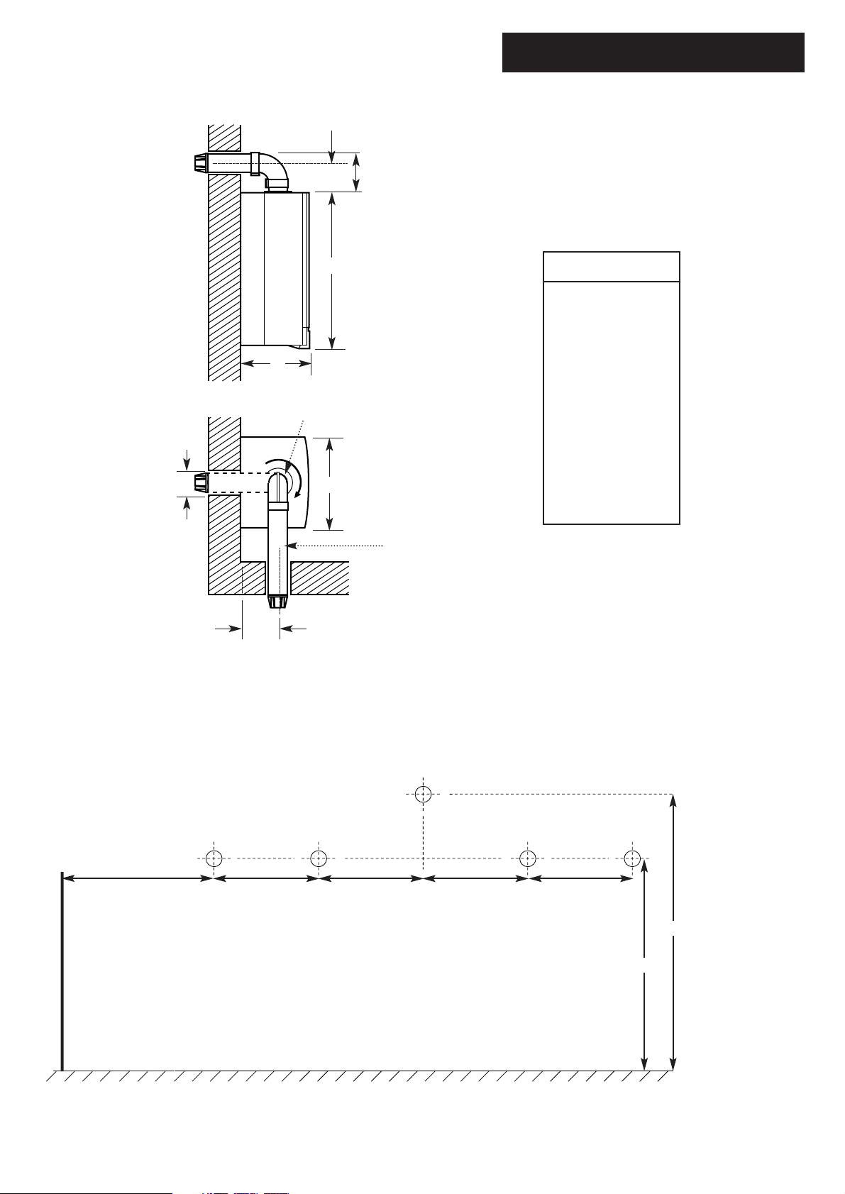
5.0 Dimensions and Fixings
8
Dimensions
A 780mm
B 345mm
C 450mm
D 107mm Ø Min.
E 200mm
F 190mm
G 143mm
360° Orientation
Tube Ø 100mm
D
C
B
A
E
G
F
65mm 65mm 65mm 65mm
Wall
View from under the appliance
Gas Inlet
Heating
Flow
Domestic Hot
Water Outlet
Cold Water
Inlet
Heating
Return
130mm
165.7mm
95mm
Left Hand Side
of Boiler
Fig. 6
Fig. 7

6.0 System Details
9
6.1 Information
1. The Baxi Combi 80Eco Combination Boiler is a
‘Water Byelaws Scheme - Approved Product’.
To comply with the Water Byelaws your attention is
drawn to the following installation requirements and
notes (IRN).
a) IRN 001 - See text of entry for installation
requirements and notes.
b) IRN 302 - Byelaw 14.
2. Reference to the WRC publications, ‘Water fittings
and materials directory’ and ‘Water supply byelaws
guide’ give full details of byelaws and the IRNs.
6.2 Central Heating Circuit
1. The appliance is suitable for fully pumped
SEALED SYSTEMS ONLY.
Treatment of Water Circulating Systems
• All recirculatory water systems will be subject to
corrosion unless an appropriate water treatment is
applied. This means that the efficiency of the
system will deteriorate as corrosion sludge
accumulates within the system, risking damage to
pump and valves, boiler noise and circulation
problems.
• For optimum performance after installation this
boiler and its associated central heating system
must be flushed in accordance with the guidelines
given in BS 7593 “Treatment of water in domestic
hot water central heating systems”.
• This must involve the use of a proprietary
cleanser, such as BetzDearborn Sentinel X300 or
X400, or Fernox Superfloc. Full instructions are
supplied with the products, but for immediate
information please contact BetzDearborn (0151
420 9563) or Fernox (01799 550 811) directly.
• For long term protection against corrosion and
scale, after flushing it is recommended that an
inhibitor such as BetzDearborn Sentinel X100, or
Fernox MB-1 or Copal is dosed in accordance with
the guidelines given in BS 7593.
Failure to flush and add inhibitor to the system
may invalidate the appliance warranty.
• It is important to check the inhibitor
concentration after installation, system modification
and at every service in accordance with the
manufacturer’s instructions. (Test kits are available
from inhibitor stockists.)
• For information or advice regarding any of the
above contact the Baxi Helpline.
6.3 Bypass
1. The boiler is fitted with an automatic integral
bypass.
6.4 System Control
1. The boiler is designed for use in a heating
system that incorporates external controls, i.e. a
minimum of a timer device.
2. Suitable timer kits are available as optional
extras.
3. For optimum operating conditions and maximum
economy the fitting of a programmable thermostat,
such as one of the Baxi Combi 80Eco Controllers,
is recommended.
Stop
Valve
Double
Check
Valve
DHW
Mains
Inlet
CH
Return
Temporary
Hose
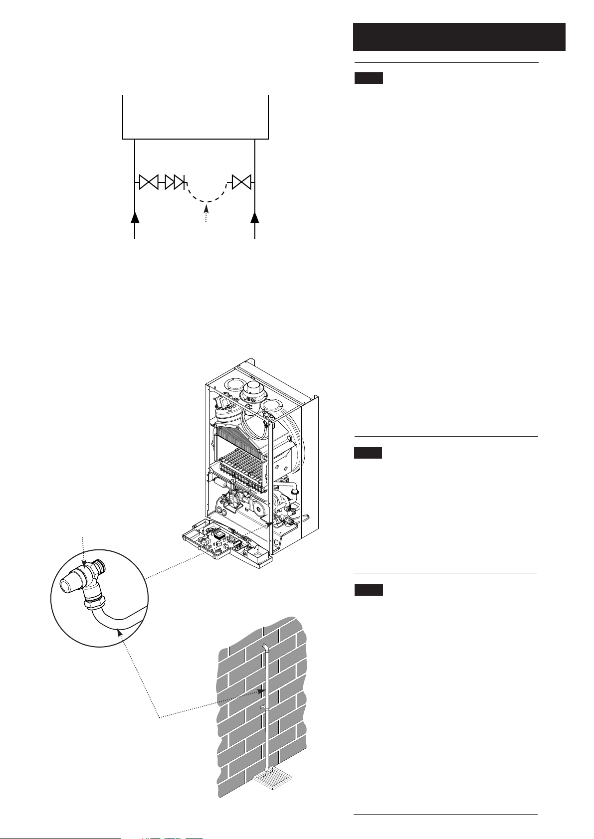
6.0 System Details
10
6.5 System Filling and Pressurising
1. A filling point connection on the central heating
return pipework must be provided to facilitate
initial filling and pressurising and also any
subsequent water loss replacement/refilling.
2. There are connection points on the mains cold
water inlet and central heating return isolating
taps to which the optional filling loop kit (Part No.
248221) can be assembled.
3. The filling method adopted must be in
accordance with the Water Supply (Water
Fittings) regulations and the Water Bylaws
(Scotland).
4. Your attention is drawn to: Paragraph 24 of
Schedule 2 Section 8 of the publication Water
Regulations Guide which gives recommendations
and guidance on approved methods for filling
sealed systems.
5. The sealed primary circuits may be filled or
replenished by means of a temporary connection
between the primary circuit and a supply pipe
provided the arrangement in accordance with
Diagram R24.2a of the Water Regulations Guide.
6. The temporary hose must be completely
removed at both ends after use.
6.6 Expansion Vessel
(Central Heating only)
1. The appliance expansion vessel is pre-charged
to 0.5 bar. Therefore, the minimum cold fill
pressure is 0.5 bar. The vessel is suitable for
correct operation for system capacities up to 125
litres. For greater system capacities an additional
expansion vessel must be fitted - refer to BS 7074
Pt 1.
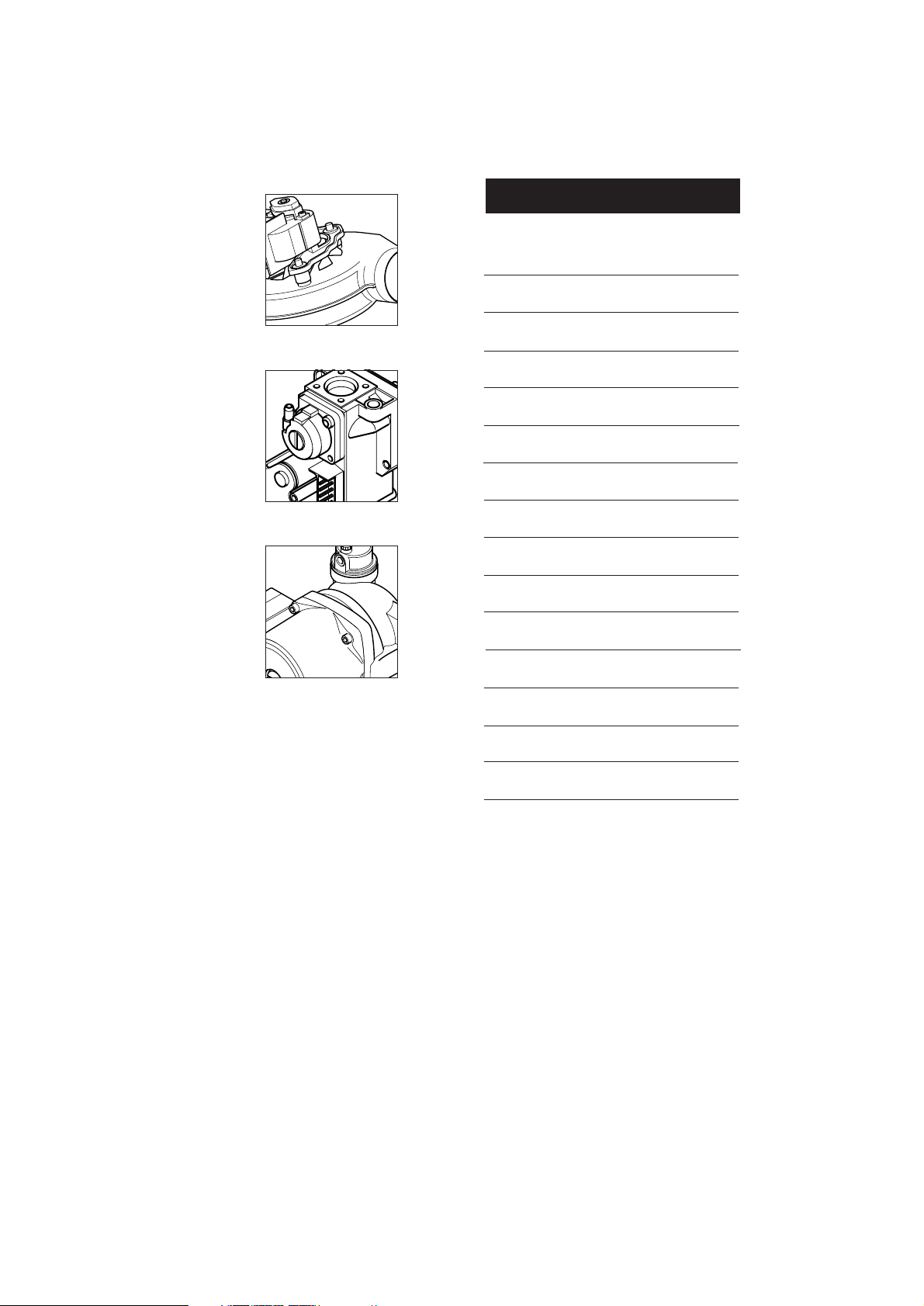
6.7 Pressure Relief Valve (Fig. 9)
1. The pressure relief valve is set at 3 bar,
therefore all pipework, fittings, etc. should be
suitable for pressures in excess of 3 bar.
2. The pressure relief discharge pipe should be
not less than 15mm dia, run continuously
downward, and discharge outside the building,
preferably over a drain (Fig. 10). It should be
routed in such a manner that no hazard occurs to
occupants or causes damage to wiring or
electrical components. The end of the pipe should
terminate facing down and towards the wall.
3. The discharge must not be above a window,
entrance or other public access. Consideration
must be given to the possibility that boiling
water/steam could discharge from the pipe.
Fig. 8
Fig. 9
Fig. 10
Pressure Relief Valve
Discharge Pipe
Stop
Valve
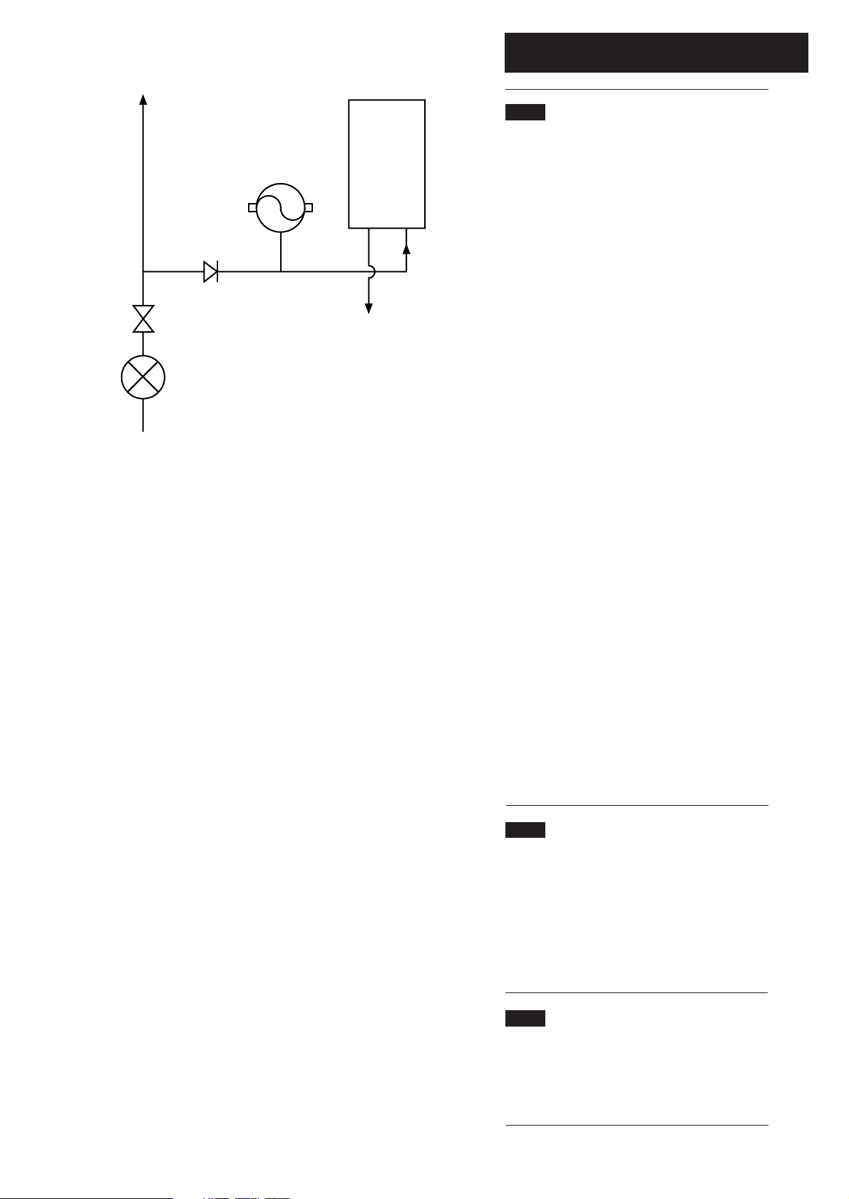
6.0 System Details
11
6.8 Domestic Hot Water Circuit
1. All DHW circuits, connections, fittings, etc.
should be fully in accordance with relevant
standards, the Water Supply (water fittings)
Regulations and the Water Bylaws (Scotland).
2. Your attention is drawn to:
Schedule 2, Section 6 of the publication Water
Regulations Guide which relates to backflow
prevention.
3. A single check valve must be fitted as shown in
Fig. 11 to prevent backflow to the supply pipe and
to ensure the efficient operation of the expansion
vessel which is required to accommodate the
thermal expansion of the water.
4. When the domestic water system includes any
device which prevents water expanding back
towards the supply (check valve, loose jumpered
stopcock, water meter, water treatment device)
then an expansion vessel must be fitted (eg.
Zilmet 160ml, R
1
/215bar).
5. If the hot water expansion is not provided for,
then high pressures can develop which may
result in damage to fittings and devices on the
system.
6. The boiler’s maximum working mains pressure
is 8 bar, therefore all pipework, connections,
fittings, etc. should be suitable for pressures in
excess of 8 bar. A pressure reducing valve must
be fitted for pressures in excess of 8 bar. The
manufacturer of any outlet fittings, such as a
shower valve, may require a lower maximum
pressure. The pressure reduction must take
account of all fittings connected to the DHW
system.
6.9 Showers
1. If a shower control is supplied from the
appliance it should be of the thermostatic or
pressure balanced type. Thermostatic type
shower valves provide the best comfort and
guard against water at too high a temperature.
Existing controls may not be suitable - refer to the
shower valve manufacturer.
6.10 Hard Water Areas
1. If the area of the installation is recognised as a
HARD WATER AREA then a suitable device
should be fitted to treat the mains water supply to
the boiler.
Boiler
Other Tap
Outlets
Expansion
Vessel
To Hot
Taps
Check
Valve
Pressure
Reducing Valve
Stop Tap
Fig. 11
7.0 Site Requirements
12
7.1 Information
1. The installation must be carried out by a CORGI
Registered Installer or other registered competent
person and be in accordance with the relevant
requirements of the current G
AS SAFETY (Installation
and Use) R
EGULATIONS, the BUILDING REGULATIONS
(Scotland)(Consolidation), the LOCAL BUILDING
REGULATIONS, the current I.E.E. WIRING REGULATIONS
and the bye laws of the LOCAL WATER UNDERTAKING.
Where no specific instruction is given reference
should be made to the relevant BRITISH
STANDARD CODES OF PRACTICE. For Ireland
install in accordance with IS 813 “I
NSTALLATION OF
GAS APPLIANCES”.
7.2 B.S. Codes of Practice
Standard Scope
BS 6891 Gas Installation.
BS 5546 Installation of hot water supplies for
domestic purposes.
BS 5449 Part 1 Forced circulation hot water systems.
BS 6798 Installation of gas fired hot water boilers.
BS 5440 Part 1 Flues.
BS 5440 Part 2 Ventilation.
BS 7074 Expansion vessels and ancillary
equipment for sealed water systems.
BS 7593 Treatment of water in domestic hot water
central heating systems.
WARNING - The addition of anything that may
interfere with the normal operation of the
appliance without the express written permission
of Baxi UK Limited could invalidate the appliance
warranty and infringe the G
AS SAFETY
(Installation and Use) REGULATIONS.
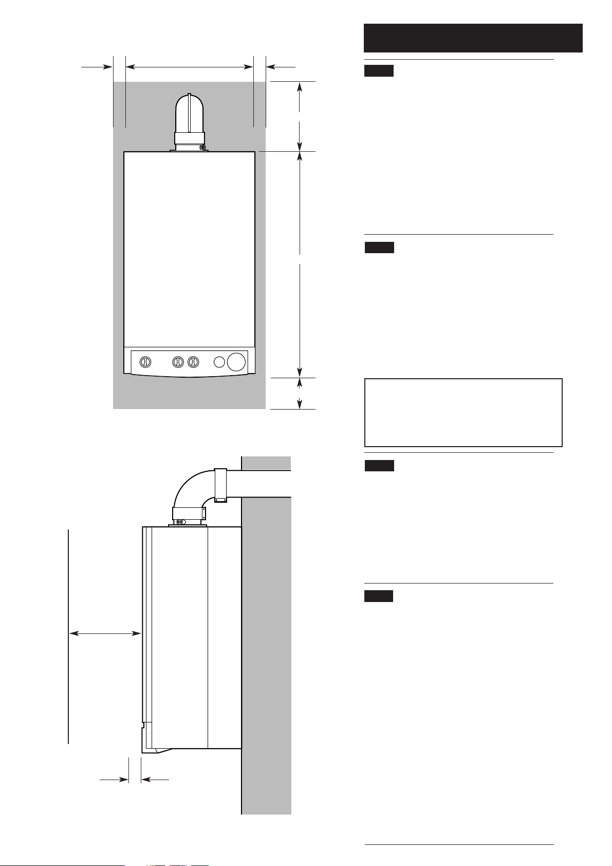
7.3 Clearances (Fig. 12 & 13)
1. A flat vertical area is required for the installation
of the boiler.
2. These dimensions include the necessary
clearances around the boiler for case removal,
spanner access and air movement. Additional
clearances may be required for the passage of
pipes around local obstructions such as joists
running parallel to the front face of the boiler.
7.4 Location
1. The boiler may be fitted to any suitable wall with
the flue passing through an outside wall or roof and
discharging to atmosphere in a position permitting
satisfactory removal of combustion products and
providing an adequate air supply. The boiler should
be fitted within the building unless otherwise
protected by a suitable enclosure i.e. garage or
outhouse. (The boiler may be fitted inside a
cupboard - see Section 7.5).
2. If the boiler is sited in an unheated enclosure then
it is recommended to leave the ON/OFF/RESET
Selector Switch in the domestic hot water and
central heating position to give frost protection.
3. If the boiler is fitted in a room containing a bath or
shower reference must be made to the current
I.E.E. W
IRING REGULATIONS and BUILDING
REGULATIONS. If the boiler is to be fitted into a
building of timber frame construction then reference
must be made to the current edition of Institute of
Gas Engineers Publication IGE/UP/7 (Gas
Installations in Timber Framed Housing).
200mm Min
780mm
450mm
200mm Min
5mm Min
5mm Min
5 mm Min
450mm Min
For Servicing
Purposes
Fig. 12
Fig. 13
In Operation

7.0 Site Requirements
13
7.5 Ventilation of Compartments
1. Where the appliance is installed in a cupboard
or compartment, no air vents are required.
2. BS 5440: Part 2 refers to room sealed
appliances installed in compartments. The
appliance will run sufficiently cool without
ventilation.
7.6 Gas Supply
1. The gas installation should be in accordance
with BS6891.
2. The connection to the appliance is a 22mm
copper tail located at the rear of the gas service
cock (Fig. 14).
3. Ensure that the pipework from the meter to the
appliance is of adequate size. Do not use pipes of
a smaller diameter than the boiler gas connection
(22mm).
7.7 Electrical Supply
1. External wiring must be correctly earthed,
polarised and in accordance with current I.E.E.
W
IRING REGULATIONS.
2. The mains supply is 230V ~ 50Hzfused at 3A.
NOTE: The method of connection to the
electricity supply must facilitate complete
electrical isolation of the appliance.
Connection may be via a fused double-pole
isolator with a contact separation of at least
3mm in all poles and servicing the boiler and
system controls only.
Fig. 14
Gas Service Cock
7.0 Site Requirements
14
Fig. 16
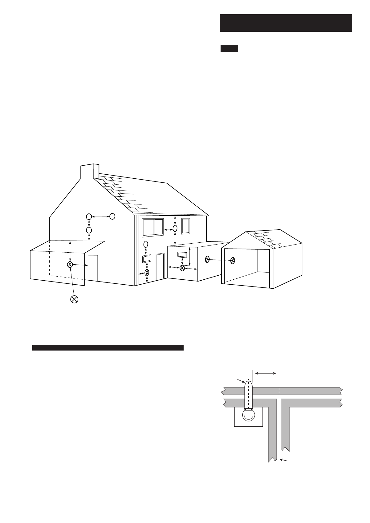
7.8 Flue
1. The flue terminal position must be in
accordance with the current editions of B.S.
5440 Part 1, and either Part J of the Building
Regulations England and Wales or Part F of
the Building Standards (Scotland)
Regulations as appropriate.
2. If the terminal discharges onto a pathway or
passageway, check that combustion products will
not cause a nuisance and that the terminal will
not obstruct the passageway.
3. If a terminal is less than 2 metres above a
balcony, above ground or above a flat roof to
which people have access, then a suitable
terminal guard must be provided.
Terminal Position with Minimum Distance (Fig. 16) (mm)
A Directly below an openable window, air vent or any other
ventilation opening. 300
B Below gutter, drain/soil pipe. 25
C Below eaves. 25
D Below a balcony/car port roof. 25
E From vertical drain pipes and soil pipes. 25
F From internal or external corners. 25
G Above adjacent ground or balcony level. 300
H From a surface facing a terminal. 600
I Facing a terminals. 1200
J From opening (door/window) in carport into dwelling. 1200
K Vertically from a terminal on the same wall. 1500
L Horizontally from a terminal on the same wall. 300
M Above an opening, air brick, opening window etc. 300
N Horizontally to an opening, air brick, opening window etc. 300
L
G
G
E
J
D
K
G
A
A
D
F
H,I
B,C
F
Likely flue positions requiring
a flue terminal guard
M
N
300 min
Terminal
Assembly
Top View Rear Flue
Property Boundary Line
 Loading...