


Installation & Servicing Instructions
Duo-tec Combi HE A Range
Gas Fired Wall Mounted Condensing
Combination Boiler
These instructions include the Benchmark Commissioning Checklist and should be left with the user for safe keeping.
© Baxi Heating UK Ltd 2013

Natural Gas
Baxi Duo-tec Combi 24 HE A
G.C.No 47 075 35
Baxi Duo-tec Combi 28 HE A
G.C.No 47 075 36
Baxi Duo-tec Combi 33 HE A
G.C.No 47 075 37
Baxi Duo-tec Combi 40 HE A
G.C.No 47 075 38
The Benchmark Scheme
Benchmark places responsibilities on both manufacturers and installers. The purpose is to ensure that customers are provided with the correct equipment for their needs, that it is installed, commissioned and serviced in accordance with the manufacturer’s instructions by competent persons and that it meets the requirements of the appropriate Building Regulations. The Benchmark Checklist can be used to demonstrate compliance with Building Regulations and should be provided to the customer for future reference.
Installers are required to carry out installation, commissioning and servicing work in accordance with the Benchmark Code of Practice which is available from the Heating and Hotwater Industry Council who manage and promote the Scheme. Visit www.centralheating.co.uk for more information.
© Baxi Heating UK Ltd 2013 All rights reserved. No part of this publication may be reproduced or transmitted in any form or by any means, or stored in any retrieval system of any nature (including in any database), in each case whether electronic, mechanical, recording or otherwise, without the prior written permission of the copyright owner, except for permitted fair dealing under Copyrights, Designs and Patents Act 1988.
Applications for the copyright owner’s permission to reproduce or make other use of any part of this publication should be made, giving details of the proposed use, to the following address:
The Company Secretary, Baxi Heating UK Ltd,
Brooks House, Coventry Road, Warwick. CV34 4LL
Full acknowledgement of author and source must be given.
WARNING: Any person who does any unauthorised act in relation to a copyright work may be liable to criminal prosecution and civil claims for damages.
Building Regulations and the Benchmark Commissioning
Checklist
Building Regulations (England & Wales) require notification of the installation of a heating appliance to the relevant Local Authority Building Control Department. From 1 April 2005 this can be achieved via a Competent Persons Self Certification Scheme as an option to notifying the Local Authority directly. Similar arrangements will follow for Scotland and will apply in Northern Ireland from 1 January 2006.
The Health & Safety Executive operates the ‘Gas Safe Register’, a self-certification scheme for gas heating appliances.
These arrangements represent a change from the situation whereby compliance with Building Regulations was accepted as being demonstrated by completion of the Benchmark Logbook (which was then left on site with the customer).
With the introduction of Self Certification Schemes, the Benchmark Logbook is being withdrawn. However, a similar document in the form of a commissioning checklist and service interval record is incorporated at the back of these instructions.
This company is a member of the Benchmark initiative and fully supports the aims of the programme. Its aim is to improve the standards of installation and commissioning of central heating systems in the UK and to encourage the regular servicing of all central heating systems to ensure safety and efficiency.
Building Regulations require that installations should comply with manufacturer's instructions. It is therefore important that the commissioning checklist is completed by the installer. The relevant section of Building Regulations only relates to dwellings. Therefore the checklist only applies if the appliance is being installed in a dwelling or some related structure.
The flowchart opposite gives guidance for installers on the process necessary to ensure compliance with Building Regulations.

 0086
0086
ISO 9001
FM 00866
2 |
© Baxi Heating UK Ltd 2013 |
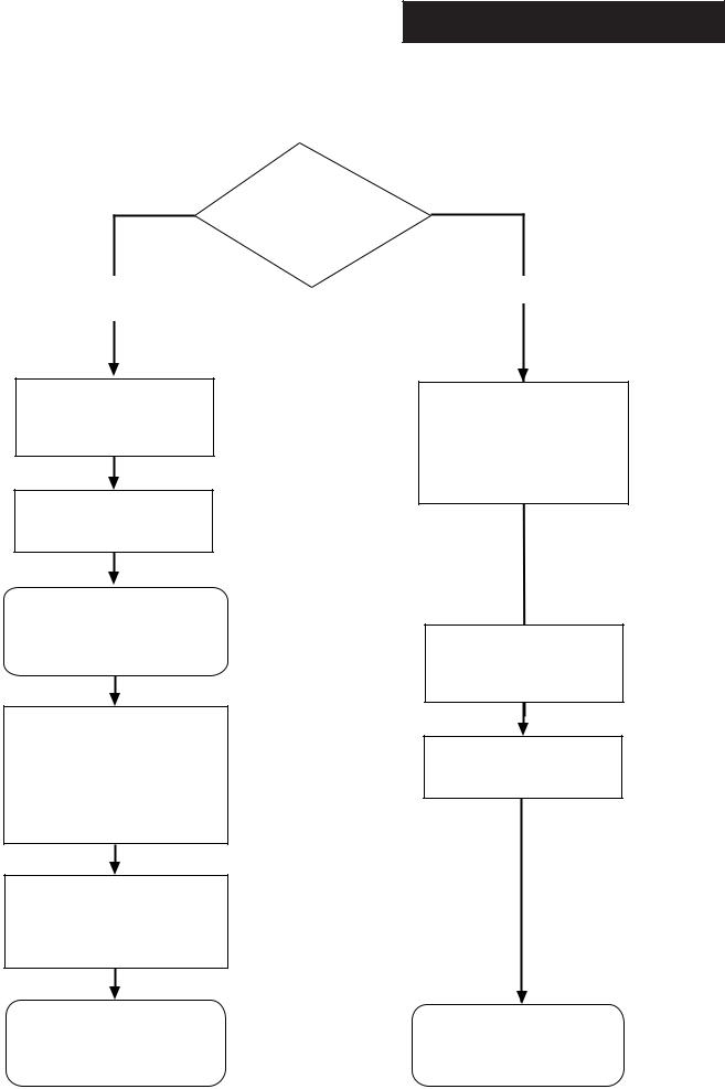
Installer Notification Guidelines
Choose Building
Regulations Notification
Route
Competent Person's
Self Certification Scheme
Install and Commission this appliance to manufacturer's instructions
Complete the
Benchmark Checklist
If you notify via the ‘Gas Safe Register’, the register will issue the Building Regulations certificate on members’ behalf
Scheme Members only
Call ‘Gas Safe Register’ on: 0800 408 5577
or log onto: www.gassaferegister.co.uk within 10 days
You must ensure that the certificate number issued by the ‘Gas Safe Register’ is written onto the Benchmark Checklist
‘Gas Safe Register’ will issue a Building Regulations Compliance Certificate to the property owner and inform the relevant LABC
Building Control
Contact your relevant Local Authority Building Control (LABC) who will arrange an inspection or contact a government approved inspector
Install and Commission this appliance to manufacturer's instructions
Complete the
Benchmark Checklist
LABC will record the data and will issue a certificate of compliance
© Baxi Heating UK Ltd 2013 |
3 |
IMPORTANT - Installation, Commissioning, Service & Repair
This appliance must be installed in accordance with the manufacturer’s instructions and the regulations in force. Read the instructions fully before installing or using the appliance.
In GB, this must be carried out by a competent person as stated in the Gas Safety (Installation & Use) Regulations.
Definition of competence: A person who works for a Gas Safe registered company and holding current certificates in the relevant ACS modules, is deemed competent.
In IE, this must be carried out by a competent person as stated in I.S. 813 “Domestic Gas Installations”.
The addition of anything that may interfere with the normal operation of the appliance without express written permission from the manufacturer or his agent could invalidate the appliance warranty. In GB this could also infringe the Gas Safety (Installation and Use) Regulations.
Warning - Check the information on the data plate is compatible with local supply conditions.
All Gas Safe registered engineers carry an ID card with their licence number and a photograph. You can check your engineer is registered by telephoning
0800 408 5500 or online at www.gassaferegister.co.uk
The boiler meets the requirements of Statutory Instrument “ The Boiler (Efficiency) Regulations 1993 No 3083” and is deemed to meet the requirements of Directive 92/42/EEC on the energy efficiency requirements for new hot water boilers fired with liquid or gaseous fuels:-
Type test for purpose of Regulation 5 certified by:
Notified Body 0085.
Product/Production certified by:
Notified Bodies 0085 & 0086.
For GB/IE only.
Legislation
This company declare that no substances harmful to health are contained in the appliance or used during appliance manufacture.
The appliance is suitable only for installation in GB and IE and should be installed in accordance with the rules in force, and only used in a suitably ventilated location.
In GB, the installation must be carried out by a Gas Safe Registered Installer. It must be carried out in accordance with the relevant requirements of the:
•Gas Safety (Installation & Use) Regulations.
•The appropriate Building Regulations either The Building Regulations, The Building Regulations (Scotland), Building Regulations (Northern Ireland).
•The Water Fittings Regulations or Water Byelaws in Scotland.
•The Current I.E.E. Wiring Regulations.
Where no specific instructions are given, reference should be made to the relevant British Standard Code of Practice.
In IE, the installation must be carried out by a competent Person and installed in accordance with the current edition of I.S. 813 ‘Domestic Gas Installations’, the current Building Regulations and reference should be made to the current ETCI rules for electrical installation.
All systems must be thoroughly flushed and treated with inhibitor (see section 6.2).
Codes of Practice - refer to the most recent version
In GB the following Codes of Practice apply:
Standard |
Scope |
BS 6891 |
Gas Installation. |
BS 5546 |
Installation of hot water supplies for domestic |
|
purposes. |
BS EN 12828 |
Heating systems in buildings. |
BS EN 14336 |
Installation & commissioning of water based |
|
heating systems. |
BS 6798 |
Installation of gas fired hot water boilers. |
BS 5440 Part 1 |
Flues. |
BS 5440 Part 2 |
Ventilation. |
BS 7074 |
Expansion vessels and ancillary equipment for |
|
sealed water systems. |
BS 7593 |
Treatment of water in domestic hot water |
|
central heating systems. |
In IE the following Codes of Practice apply: |
|
Standard |
Scope |
I.S. 813 |
Domestic Gas Installations. |
The following standards give valuable additional information; |
|
BS 5546 |
Installation of hot water supplies for domestic |
|
purposes. |
BS EN 12828 |
Heating systems in buildings. |
BS EN 14336 |
Installation & commissioning of water based |
|
heating systems. |
BS 7074 |
Expansion vessels and ancillary equipment for |
|
sealed water systems. |
BS 7593 |
Treatment of water in domestic hot water |
|
central heating systems. |
4 |
© Baxi Heating UK Ltd 2013 |

Safe Manual Handling
General
The following advice should be adhered to, from when first handling the boiler to the final stages of installation, and also during maintenance.
Most injuries as a result of inappropriate handling and lifting are to the back, but all other parts of the body are vulnerable, particularly shoulders, arms and hands. Health & Safety is the responsibility of EVERYONE.
There is no ‘safe’ limit for one man - each person has different capabilities. The boiler should be handled and lifted by TWO PEOPLE.
Do not handle or lift unless you feel physically able.
Wear appropriate Personal Protection Equipment e.g. protective gloves, safety footwear etc.
Preparation
Co-ordinate movements - know where, and when, you are both going.
Minimise the number of times needed to move the boiler - plan ahead.
Always ensure when handling or lifting the route is clear and unobstructed. If possible avoid steps, wet or slippery surfaces, unlit areas etc. and take special care on ladders/into lofts.
Technique
When handling or lifting always use safe techniques - keep your back straight, bend your knees. Don’t twist - move your feet, avoid bending forwards and sideways and keep the load as close to your body as possible.
Where possible transport the boiler using a sack truck or other suitable trolley.
Always grip the boiler firmly, and before lifting feel where the weight is concentrated to establish the centre of gravity, repositioning yourself as necessary. See the ‘Installation’ section of these instructions for recommended lift points.
Remember
The circumstances of each installation are different. Always asses the risks associated with handling and lifting according to the individual conditions.
If at any time when installing the boiler you feel that you may have injured yourself STOP !!
DO NOT ‘work through’ the pain - you may cause further injury.
IF IN ANY DOUBT DO NOT HANDLE OR LIFT THE BOILER - OBTAIN ADVICE OR ASSISTANCE BEFORE PROCEEDING !!
© Baxi Heating UK Ltd 2013 |
5 |

CONTENTS
|
Section |
|
Page |
|
|
1.0 |
Introduction |
7 |
|
|
|
|
|
|
|
2.0 |
General Layout |
8 |
|
|
|
|
|
|
|
3.0 |
Appliance Operation |
9 |
|
|
|
|
|
|
|
4.0 |
Technical Data |
10 |
|
|
|
|
|
|
|
5.0 |
Dimensions and Fixings |
11 |
|
|
|
|
|
|
|
6.0 |
System Details |
12 |
|
|
|
|
|
|
|
7.0 |
Site Requirements |
15 |
|
|
|
|
|
|
|
8.0 |
Flue Options |
21 |
|
|
|
|
|
|
|
9.0 |
Plume Displacement |
26 |
|
|
|
|
|
|
|
10.0 |
Installation |
30 |
|
|
|
|
|
|
|
11.0 |
Commissioning |
35 |
|
|
|
|
|
|
|
12.0 |
Completion |
37 |
|
|
|
|
|
|
|
13.0 |
Servicing |
38 |
|
|
|
|
|
|
|
14.0 |
Changing Components |
40 |
|
|
|
|
|
|
|
15.0 |
Setting the Gas Valve |
49 |
|
|
|
|
|
|
|
16.0 |
Electrical |
50 |
|
|
|
|
|
|
|
17.0 |
Short Parts List |
51 |
|
|
|
|
|
|
|
18.0 |
Fault Finding |
52 |
|
|
|
|
|
|
|
|
|
Benchmark Checklist |
58 |
|
|
|
|
|
6 |
© Baxi Heating UK Ltd 2013 |
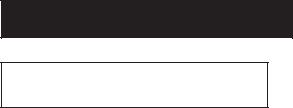
Case Front Panel
Control Box
Fig. 1 |
Data Badge |
|
Information Label
1.0Introduction
1.1Description
1.The Baxi Duo-tec Combi HE A is a fully automatic gas fired wall mounted condensing combination boiler. It is room sealed and fan assisted, and will serve central heating and mains fed domestic hot water.
2.The boiler is set to give a maximum output of :-
24 models - |
24 kW DHW |
|
21 kW CH (Condensing) |
28 models - |
28 kW DHW |
|
25.9 kW CH (Condensing) |
33 models - |
33 kW DHW |
|
30.3 kW CH (Condensing) |
40 models - |
40 kW DHW |
34.4kW CH (Condensing)
3.It is designed for use on Natural Gas (G20).
4.The boiler is suitable for use only on fully pumped sealed heating systems. Priority is given to domestic hot water.
5.The boiler data badge gives details of the model, serial number and Gas Council number and is situated on the inner door panel. It is visible when the case front panel is removed (Fig. 1).
6.The boiler model name and serial number are also shown on the information label on the underside of the facia. This is for user reference.
7.The boiler is intended to be installed in residential / commercial / light industrial E.M.C. environments on a governed meter supply only.
8.The boiler must be installed with one of the purpose designed flues such as the standard horizontal telescopic flue kit, part no. 5118069.
9.All systems must be thoroughly flushed and treated with inhibitor (see section 6.2).
Important: If the boiler is installed at a high point in the system it is strongly recommended that Automatic Air Vent Kit 720004701 is fitted.
1.2Optional Extras
Integral timers, RF room thermostats etc. are available as optional extras.
1.3Contents of Pack
The pack contains:-
•Boiler
•Wall Plate (including taps)
•Set of Pipe Connections
•Template & ‘Quick Fit’ Guide
•Literature Pack
•Filling Loop
© Baxi Heating UK Ltd 2013 |
|
7 |

23 |
|
1 |
15 |
|
|
22 |
|
14 |
|
21 |
13 |
|
16 |
7 |
20 |
|
10
9 |
8 |
|

 12
12
2
3 |
11 |
2.0General Layout
2.1Layout
1.Expansion Vessel
2.Automatic Air Vent
3.DHW Plate Heat Exchanger
4.Circulation Pump
5.Drain Off Point
6.Pressure Relief Valve
7.Selector Switch
8.Central Heating System Pressure Gauge
9.PCB
10.Control Box
11.3-Way Valve Assembly
12.Condensate Trap
13.Flame Sensing Electrode
14.Spark Electrode
15.Primary Heat Exchanger
16.Fan Assembly
17.On/Off/Reset Selector Switch
18.Central Heating Temperature Control
19.Hot Water Temperature Control
20.Venturi
21.Air/Gas Collector
22.Combustion Box Cover & Burner
23.Igniter
24.Burner On Light
25.Central Heating Mode Light
26.Domestic Hot Water Mode Light
27.Display
28.Position of Optional Integral Timer
5
4 |
6 |
|
25 26
|
2 |
1 |
3 |
0 |
4 |
|
bar |
|
17 |
27 |
24 |
18 |
19 |
8 |
28 |
8 |
© Baxi Heating UK Ltd 2013 |
|
|
|
|
|
|

1
Central Heating Circuit
|
|
|
|
|
|
2 |
|
|
|
|
|
|
|
3 |
4 |
7 |
|
|
|
26 |
|
|
|
|
||
|
|
|
|
|
|
|
||
|
|
|
20 |
|
5 |
|
6 |
|
|
|
|
|
|
|
|||
|
|
25 |
|
|
|
|
8 |
|
|
|
24 |
|
|
|
|
||
|
18 |
|
|
|
|
|
||
|
|
|
|
|
|
|
||
|
|
22 |
|
|
|
9 |
|
|
|
|
|
|
|
|
11 |
||
|
|
|
|
23 |
|
|
||
|
21 |
|
|
|
|
|
||
|
|
|
|
|
|
10 |
||
|
|
|
|
|
|
|
17 |
|
|
16 |
|
15 |
14 |
|
13 |
12 |
|
|
Fig. 2 |
|
|
|
|
|
|
|
Key |
|
|
|
|
|
|
||
1 |
Primary Heat Exchanger |
|
15 Domestic Hot Water Outlet |
|||||
2 |
Burner |
|
|
|||||
|
|
16 |
Heating Flow |
|
||||
3 |
Ignition Electrodes |
|
|
|
||||
|
|
17 |
Pressure Gauge |
|
||||
4 |
Flame Sensing Electrode |
|
|
|||||
|
18 |
Water Pressure Sensor |
||||||
5 |
Gas Valve |
|
|
|||||
|
|
20 |
Fan |
|
|
|||
6 |
Pump |
|
|
|
|
|||
|
|
21 |
Diverter Valve Assembly |
|||||
7 |
Automatic Air Vent |
|
|
|||||
|
|
22 |
Diverter Valve Motor |
|
||||
8 |
Plate Heat Exchanger/Automatic By-pass |
|
||||||
23 Domestic Hot Water Flow Temperature Sensor |
||||||||
9 |
Flow Sensor with Filter & Regulator |
|
||||||
|
24 |
Safety Thermostat |
|
|||||
10 |
Pressure Relief Valve |
|
|
|
||||
|
|
25 Central Heating Temperature Sensor |
||||||
11 |
Boiler Drain Point |
|
|
|||||
|
|
26 |
Expansion Vessel |
|
||||
12 |
Heating Return |
|
|
|
||||
|
|
|
|
|
|
|||
13 Cold Water Inlet On/Off Valve and Filter |
|
|
|
|
||||
14 |
Gas Inlet |
|
|
|
|
|
|
|
1
Domestic Hot Water Circuit
|
|
|
|
|
2 |
|
26 |
|
3 |
4 |
7 |
|
|
|
|
||
|
|
20 |
5 |
|
6 |
|
|
|
|
||
|
25 |
|
|
|
8 |
18 |
24 |
|
|
|
|
|
|
|
|
||
|
|
|
|
|
|
|
22 |
|
|
9 |
|
|
|
|
|
11 |
|
|
|
|
23 |
|
|
21 |
|
|
|
10 |
|
|
|
|
|
||
|
|
|
|
|
17 |
16 |
15 |
|
14 |
13 |
12 |
Fig. 3
3.0Appliance Operation
3.1Central Heating Mode (Fig. 2)
1.With a demand for heating, the pump circulates water through the primary circuit.
2.Once main burner ignites the fan speed controls the gas rate to maintain the heating temperature measured by the temperature sensor.
3.When the flow temperature exceeds the setting temperature, a 3 minute delay occurs before the burner relights automatically (anti-cycling). The pump continues to run during this period.
4.When the demand is satisfied the burner is extinguished and the pump continues to run for a period of 3 minutes (Pump Overrun).
3.2Domestic Hot Water Mode (Fig. 3)
1.Priority is given to the domestic hot water supply. A demand at a tap or shower will override any central heating requirement.
2.The flow of water will operate the Hall Effect Sensor which requests the 3 way valve to change position. This will allow the pump to circulate the primary water through the DHW plate heat exchanger.
3.The burner will light automatically and the temperature of the domestic hot water is controlled by the temperature sensor.
4.When the domestic hot water demand ceases the burner will extinguish and the diverter valve will remain in the domestic hot water mode, unless there is a demand for central heating.
IMPORTANT: When the selector switch is in the ‘0’ (Off) position the electrical supply to the boiler is isolated. The boiler will not operate and the integral timer will require resetting once the selector switch is set to either Position (i) or Position (ii).
3.3Frost Protection Mode
1.The frost protection mode is integral to the appliance and functions only with the selector switch (see Section 2.1) in the domestic hot water and central heating position. If the system temperature falls below 5° C then the boiler will fire on its minimum setting until a flow temperature of 30° C is reached. Further protection can be incorporated by using a system frost thermostat.
3.4Pump Protection
1. With the selector switch (see Section 2.1) in either the central heating or central heating and domestic hot water position, the pump will automatically operate for 1 minute in every 24 hours to prevent sticking.
© Baxi Heating UK Ltd 2013 |
9 |
Appliance Type |
|
|
|
C13 |
C33 |
C53 |
|
|
|||||
Appliance Category |
CAT I 2H |
|
|
|
|||||||||
Heat Input CH (Net) |
Max |
Min |
|
|
|||||||||
24 model |
|
kW |
20.5 |
7 |
|
|
|||||||
28 model |
|
kW |
24.7 |
9 |
|
|
|||||||
33 model |
|
kW |
28.9 |
9.7 |
|
|
|||||||
40 model |
|
kW |
32.8 |
9.9 |
|
|
|||||||
|
|
|
|
|
|
|
|
||||||
Heat Input CH (Gross) |
Max |
Min |
|
|
|||||||||
24 model |
kW |
22.7 |
7.8 |
|
|
||||||||
28 model |
kW |
27.4 |
10 |
|
|
||||||||
33 model |
kW |
32.1 |
10.8 |
|
|
||||||||
40 model |
kW |
36.4 |
11 |
|
|
||||||||
|
|
|
|
|
|
|
|
|
|
|
|
|
|
Heat Output CH (Non-Condensing) |
|
|
|
||||||||||
|
|
|
|
|
|
|
|
|
|
Max |
Min |
|
|
24 model |
|
kW |
20 |
6.8 |
|
|
|||||||
28 model |
|
kW |
24 |
8.7 |
|
|
|||||||
33 model |
|
kW |
28 |
9.4 |
|
|
|||||||
40 model |
|
kW |
32 |
9.6 |
|
|
|||||||
|
|
|
|
|
|
|
|
|
|
|
|||
Heat Output CH (Condensing) |
|
|
|
||||||||||
|
|
|
|
|
|
|
|
|
|
Max |
Min |
|
|
24 model |
|
kW |
21 |
7.4 |
|
|
|||||||
28 model |
|
kW |
25.9 |
9.5 |
|
|
|||||||
33 model |
|
kW |
30.3 |
10.2 |
|
|
|||||||
40 model |
|
kW |
34.4 |
12.1 |
|
|
|||||||
|
|
|
|
|
|
|
|
|
|
|
|
||
|
Heat Input DHW (Net) |
Max |
|
|
|
||||||||
|
24 model |
|
kW |
24.7 |
|
|
|
||||||
|
28 model |
|
kW |
28.9 |
|
|
|
||||||
|
33 model |
|
kW |
34 |
|
|
|
||||||
|
40 model |
|
kW |
41.2 |
|
|
|
||||||
|
|
|
|
|
|
|
|||||||
Heat Input DHW (Gross) |
Max |
|
|
|
|||||||||
24 model |
|
kW |
27.4 |
|
|
|
|||||||
28 model |
|
kW |
32.1 |
|
|
|
|||||||
33 model |
|
kW |
37.7 |
|
|
|
|||||||
40 model |
|
kW |
45.7 |
|
|
|
|||||||
|
Heat Output DHW |
Max |
|
|
|
||||||||
|
24 model |
|
kW |
24 |
|
|
|
||||||
|
28 model |
|
kW |
28 |
|
|
|
||||||
|
33 model |
|
kW |
33 |
|
|
|
||||||
|
40 model |
|
kW |
40 |
|
|
|
||||||
|
|
|
|
|
|
|
|
|
|||||
|
|
Max Gas Rate (Natural Gas - G20) |
|
|
|
||||||||
|
|
|
|
|
|
|
(After 10 mins) |
|
|
|
|||
|
|
24 model |
|
m3/h |
2.61 |
|
|
|
|||||
|
|
28 model |
|
m3/h |
3.1 |
|
|
|
|||||
|
|
33 model |
|
m3/h |
3.6 |
|
|
|
|||||
|
|
40 model |
|
m3/h |
4.36 |
|
|
|
|||||
SEDBUK Declaration
The efficiency for all models is 91.1%
This value is used in the UK Government’s Standard Assessment Procedure (SAP) for energy rating of dwellings. The test data from which it has been calculated has been certified by 0087.
NOTE: All data in this section are nominal values and subject to normal production tolerances.
10 © Baxi Heating UK Ltd 2013
4.0Technical Data
4.1Duo-tec Combi 24, 28, 33 & 40 HE A
Inlet Pressure (Natural Gas - G20)
mbar 20
Injector (Natural Gas - G20)
7.5mm (24 & 28) 12mm (33 & 40)
Electrical Supply 230V~ 50Hz (Appliance must be connected to an earthed supply)
Power Consumption
155W (24, 28) 160W (33 & 40)
Electrical Protection
IPX0D (with timer) IPX5D (without timer)
External Fuse Rating |
3A |
|
|
|
|
Internal Fuse Rating |
F2L |
|
Condensate Drain
To accept 21.5mm (3/4 in) plastic waste pipe
Flue Terminal |
Diameter |
|
100mm |
|||
Dimensions |
Projection |
125mm |
||||
|
|
|
|
|
||
Connections |
|
|
copper tails |
|||
Gas Supply |
|
|
- |
22mm |
||
Central Heating Flow |
|
|
- |
22mm |
||
Central Heating Return |
- |
22mm |
||||
Cold Water Mains Inlet |
- |
15mm |
||||
DHW Flow |
|
|
- |
15mm |
||
Pressure Relief Discharge |
- |
15mm |
||||
|
|
|
|
|
|
|
Outercase Dimensions |
|
|
||||
Casing Height |
|
|
|
- 780mm |
||
Overall Height Inc Flue Elbow |
|
- 965mm |
||||
Casing Width |
|
|
|
- 450mm |
||
Casing Depth |
|
|
|
- 345mm |
||
|
|
|
|
|
|
|
Clearances |
|
|
|
|
||
Above Casing |
200 mm Min |
|
||||
Below Casing |
150 mm Min* |
|
||||
Front |
450 mm Min (For Servicing) |
|||||
Front |
5 mm Min (In Operation) |
|||||
L.H. Side |
5 mm Min |
|
||||
R.H. Side |
5 mm Min (In Operation) |
|||||
*This is MINIMUM recommended dimension. Greater clearance will aid installation and maintenance.
Weights |
|
|
(24 model) |
Packaged Boiler Carton |
48.6 kg |
Installation Lift Weight |
43.6 kg |
|
(28 model) |
Packaged Boiler Carton |
49.2 kg |
Installation Lift Weight |
44.2 kg |
|
(33 & 40 model) |
Packaged Boiler Carton |
51kg |
Installation Lift Weight |
46kg |
Metre (wg)
NOx Class |
|
5 |
|
|
|
|
|
Central Heating Primary Circuit |
|
|
|
||||
Pressures |
|
|
|
|
|
|
|
|
|
|
|
|
bar |
||
Safety Discharge |
|
|
|
3 |
|
|
|
Max Operating |
|
|
|
2.5 |
|
||
Min Operating |
|
|
|
0.5 |
|
||
Recommended Operating Range |
1-2 |
|
|||||
|
|
|
|
|
|
|
|
DHW Circuit |
|
bar |
|
|
|
||
Pressures |
|
|
|
|
|
|
|
Max Operating |
|
8 |
|
|
|
|
|
Min Operating |
|
0.15 |
|
|
|
||
|
|
|
|
|
|
|
|
Flow Rates |
(24) |
(28) |
|
(33) |
(40) |
||
|
|
l/min |
l/min |
l/min |
l/min |
||
DHW Flow Rate |
|
|
|
|
|
|
|
@ 30o C Rise |
11.43 |
13.3 |
|
15.7 |
19.1 |
||
DHW Flow Rate |
|
|
|
|
|
|
|
@ 35o C Rise |
9.8 |
11.5 |
|
13.5 |
16.4 |
||
Min Working |
|
|
|
|
|
|
|
DHW Flow Rate |
2 |
2 |
|
2 |
2 |
|
|
IMPORTANT: Where Low Flow Taps or Fittings are intended to be used in the DHW system connected it is strongly recommended that the DHW flow rate DOES NOT fall below 2.5l/min. This will ensure reliable operation of the DHW function.
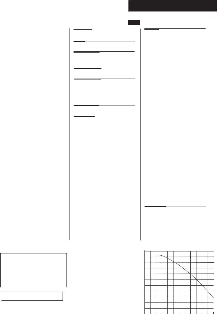
Pump |
|
|
|
|
Available Head |
See graph below |
|
|
|
|
|
|
||
Expansion Vessel |
- (For Central Heating only. |
|||
Integral with appliance) |
|
|
|
|
|
|
bar |
|
|
Min Pre-charge Pressure |
0.5 |
|
|
|
|
|
(24 & 28) |
(33 & 40) |
|
|
|
litre |
litre |
|
Max Capacity of |
|
|
|
|
CH System |
|
125 |
155 |
|
Primary Water Content |
|
|
|
|
of Boiler (unpressurised) |
2.5 |
2.8 |
|
|
Temperatures
C.H. Flow Temp (adjustable)
25°C to 80°C max (± 5°C)
D.H.W. Flow Temp (adjustable)
35°C to 60°C max (± 5°C) dependent upon flow rate
Pump - Available Head
5.5
5
4.5
4
3.5
3
2.5
2
1.5
1
0.5
0
0 |
200 |
400 |
600 |
800 |
1000 |
1200 |
Flow Rate (l/h)
5.0 Dimensions and Fixings
|
|
|
Dimensions |
|
At least 1.5° |
G |
E |
A |
780mm |
|
|
|
|
|
|
|
|
B |
345mm |
|
|
|
C |
450mm |
|
A |
|
D 116mm Ø Min. |
|
|
|
|
||
|
|
|
E |
185mm |
|
|
|
|
(207mm for 80/125mm |
|
|
|
|
flue systems) |
|
|
|
F |
145mm |
B |
|
|
G |
131mm |
360° Orientation |
H 180mm |
|
|
||
H |
J |
270mm |
|
|
|
D |
|
|
C |
|
|
J |
|
|
Tube Ø 100mm |
||
F |
|
|
|
|
Tap Rail |
32.5 mm |
|
|
|
|
|
|
|
|
|
|
|
|
|
|
|
|
|
|||||
|
|
|
|
|
|
|
|
|
|
|
|
|
|
|
|
|
|
|
|
|||
|
Condensate |
|
|
|
|
|
|
|
|
|
|
|
|
|
|
|
|
|
||||
|
|
Drain |
|
|
|
|
|
|
|
|
|
|
|
|
|
|
|
|
|
|||
|
|
65 mm |
65 mm |
|
|
|
65 mm |
|
|
65 mm |
|
65 mm |
|
|||||||||
Heating |
|
Domestic Hot |
Gas |
ColdWater |
Heating |
Pressure Relief |
||||||||||||||||
Flow |
|
Water Outlet |
Inlet |
Inlet |
Return |
|
|
Valve |
||||||||||||||
(22mm) |
|
(15mm) |
|
(22mm) |
(15mm) |
(22mm) |
|
(15mm) |
||||||||||||||
|
|
|
|
|
|
|
|
|
|
|
|
|
|
|
|
|
|
|
|
|
|
|
|
|
|
|
|
|
|
|
|
|
|
|
|
|
|
|
|
|
|
|
|
|
|
|
|
|
|
|
|
|
|
|
|
|
|
|
|
|
|
|
|
|
|
|
|
|
© Baxi Heating UK Ltd 2013 |
11 |

6.0System Details
6.1Information
1.The Baxi Duo-tec Combi HE A Condensing Combination Boiler is a ‘Water Byelaws Scheme - Approved Product’.
To comply with the Water Byelaws your attention is drawn to the following installation requirements and notes (IRN).
a) IRN 001 - See text of entry for installation
|
requirements and notes. |
b) IRN 302 - |
Byelaw 14. |
2. Reference to the WRc publications, ‘Water fittings and materials directory’ and ‘Water supply byelaws guide’ give full details of byelaws and the IRNs.
6.2Central Heating Circuit
1.The appliance is suitable for fully pumped SEALED SYSTEMS ONLY.
Treatment of Water Circulating Systems
•All recirculatory water systems will be subject to corrosion unless an appropriate water treatment is applied. This means that the efficiency of the system will deteriorate as corrosion sludge accumulates within the system, risking damage to pump and valves, boiler noise and circulation problems.
•When fitting new systems flux will be evident within the system, which can lead to damage of system components.
•All systems must be thoroughly drained and flushed out using, for example, Sentinel X300 or X400 or Fernox F3. They should be used following the flushing agent manufacturer’s instructions.
•System additives - corrosion inhibitors and flushing agents/descalers should comply to BS7593 requirements, e.g. Sentinel X100 and Fernox MB-1 which should be used following the inhibitor manufacturer’s instructions.
•Full instructions are supplied with the products, for further information contact Sentinel (0800 389 4670) or Fernox (0870 870 0362)
Failure to flush and add inhibitor to the system will invalidate the appliance warranty.
•It is important to check the inhibitor concentration after installation, system modification and at every service in accordance with the manufacturer’s instructions. (Test kits are available from inhibitor stockists.)
•For information or advice regarding any of the above contact Technical Enquiries.
6.3Bypass
1. The boiler utilises the primary side of the DHW plate heat exchanger as an automatic integral bypass.
6.4System Control
1.Further external controls (e.g. room thermostat) should be fitted to optimise the economical operation of the boiler.
12 © Baxi Heating UK Ltd 2013
Stop |
Double |
|
Check |
||
Valve |
||
Valve |
||
|
||
DHW |
Temporary |
|
Loop |
||
Mains |
||
|
||
Inlet |
|
Fig. 4
Stop
Valve
CH
Return
Filling Loop 


Connections
Fig. 5
Fig. 6
Pressure Relief Valve
Discharge Pipe
6.0System Details
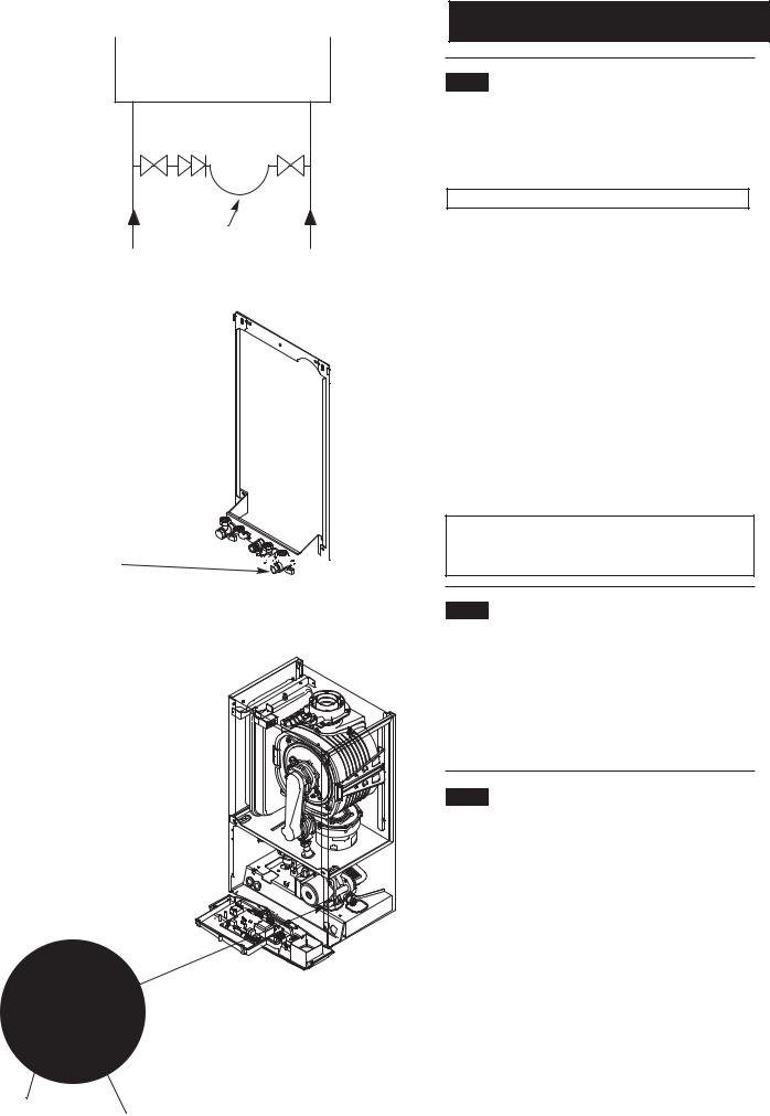
6.5System Filling and Pressurising
1.A filling point connection on the central heating return pipework must be provided to facilitate initial filling and pressurising and also any subsequent water loss replacement/refilling.
A filling loop & instructions are provided with the boiler
2.The filling method adopted must be in accordance with all relevant water supply regulations and use approved equipment.
3.Your attention is drawn to:
for GB: Guidance G24.2 and recommendation R24.2 of the Water Regulations Guide.
for IE: the current edition of I.S. 813 “Domestic Gas Installations”.
4. The sealed primary circuits may be filled or replenished by means of a temporary connection between the circuit and a supply pipe, provided a ‘Listed’ double check valve or some other no less effective backflow prevention device is permanently connected at the inlet to the circuit and the temporary connection is removed after use.
IMPORTANT: If the boiler is installed at a high point in the system it is strongly recommended that Automatic Air Vent Kit 720004701 is fitted.
6.6Expansion Vessel (Central Heating only)
1.The appliance expansion vessel is pre-charged to 0.5 bar. Therefore, the minimum cold fill pressure is 0.5 bar. The vessel is suitable for correct operation for system capacities up to 125 litres. For greater system capacities an additional expansion vessel must be fitted. For GB refer to BS 7074 Pt 1. For IE, the current edition of I.S. 813 “Domestic Gas Installations”.
6.7Safety Pressure Relief Valve (Fig. 6)
1.The pressure relief valve is set at 3 bar, therefore all pipework, fittings, etc. should be suitable for pressures in excess of 3 bar and temperature in excess of 100°C.
2.The pressure relief discharge pipe should be not less than 15mm dia, run continuously downward, and discharge outside the building, preferably over a drain. It should be routed in such a manner that no hazard occurs to occupants or causes damage to wiring or electrical components. The end of the pipe should terminate facing down and towards the wall.
3.The discharge must not be above a window, entrance or other public access. Consideration must be given to the possibility that boiling water/steam could discharge from the pipe.
4.A remote relief valve kit is available to enable the boiler to be installed in cellars or similar locations below outside ground level (kit no. 5121379).
© Baxi Heating UK Ltd 2013 |
|
13 |
 Other Tap
Outlets
Expansion |
Boiler |
|
|
Vessel* |
|
Check
Valve*
Pressure Reducer
 Valve*
Stop Tap
To Hot
Taps
* See 6.8 for instances when these items may be required
Fig. 7
6.0System Details
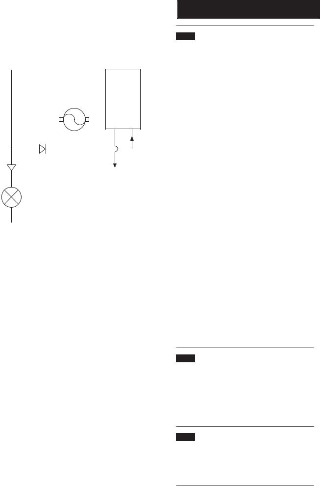
6.8Domestic Hot Water Circuit (Fig. 7)
1.All DHW circuits, connections, fittings, etc. should be fully in accordance with relevant standards and water supply regulations.
2.Your attention is drawn to:
for GB: Guidance G17 to G24 and recommendation R17 to R24 of the Water Regulations Guide.
for IE: the current edition of I.S. 813 “Domestic Gas Installations”.
3.The Water Regulations recommendations for England and Wales prohibits backflow from appliances into the wholesome water supply due to thermal expansion. However this type of instantaneous combination boiler, with less than 15 litres of stored capacity, does not require any backflow prevention device as any thermal expansion is accommodated within the appliance.
It is possible in certain circumstances that other cold water demands (e.g. washing machines, flushing of W.C.s) may affect the DHW function of the boiler. In these instances the fitting of a backflow prevention device and expansion vessel is recommended.
4.Also if there is an existing check valve, loose jumpered stop cock, water meter or water treatment device already fitted to the wholesome water supply connected to the boiler domestic hot water (DHW) inlet supply then a suitable expansion device may be required.
5.The boiler’s maximum working mains pressure is 8 bar, therefore all pipework, connections, fittings, etc. should be suitable for pressures in excess of 8 bar. A pressure reducing valve must be fitted for pressures in excess of 8 bar. The manufacturer of any outlet fittings, such as a shower valve, may require a lower maximum pressure. The pressure reduction must take account of all fittings connected to the DHW system.
6.9Showers
1. If a shower control is supplied from the appliance it should be of the thermostatic or pressure balanced type. Thermostatic type shower valves provide the best comfort and guard against water at too high a temperature. Existing controls may not be suitable - refer to the shower valve manufacturer.
6.10Hard Water Areas
1.If the area of the installation is recognised as a HARD WATER AREA then a suitable device should be fitted to treat the mains water supply to the boiler. Contact your Water Distribution Company for advice on suitable devices.
14 © Baxi Heating UK Ltd 2013

|
|
450mm |
|
|
|||
5mm Min |
|
|
|
5mm Min |
|||
|
|
|
|
|
|
|
|
|
|
|
|
|
|
|
|
200mm Min (300mm Min if using 80/125mm flueing system)
780mm
150mm Min*
Fig. 8
7.0Site Requirements
7.1Location
1.The boiler may be fitted to any suitable wall with the flue passing through an outside wall or roof and discharging to atmosphere in a position permitting satisfactory removal of combustion products and providing an adequate air supply. The boiler should be fitted within the building unless otherwise protected by a suitable enclosure i.e. garage or outhouse. (The boiler may be fitted inside a cupboard-see Section 7.3).
2.If the boiler is sited in an unheated enclosure then it is recommended to leave the ON/OFF Selector Switch in the domestic hot water and central heating position to give frost protection.
3.If the boiler is fitted in a room containing a bath or shower reference must be made to the relevant requirements.
In GB this is the current I.E.E. Wiring Regulations and Building Regulations.
In IE reference should be made to the current edition of I.S.
813“Domestic Gas Installations” and the current ETCI rules.
4.If the boiler is to be fitted into a building of timber frame construction then reference must be made to the current edition of Institute of Gas Engineers Publication IGE/UP/7 (Gas Installations in Timber Framed Housing).
*This is the MINIMUM recommended dimension. Greater clearance will aid installation and maintenance.
At least 1.5° |
7.2 |
Clearances (Figs. 8 & 9) |
|
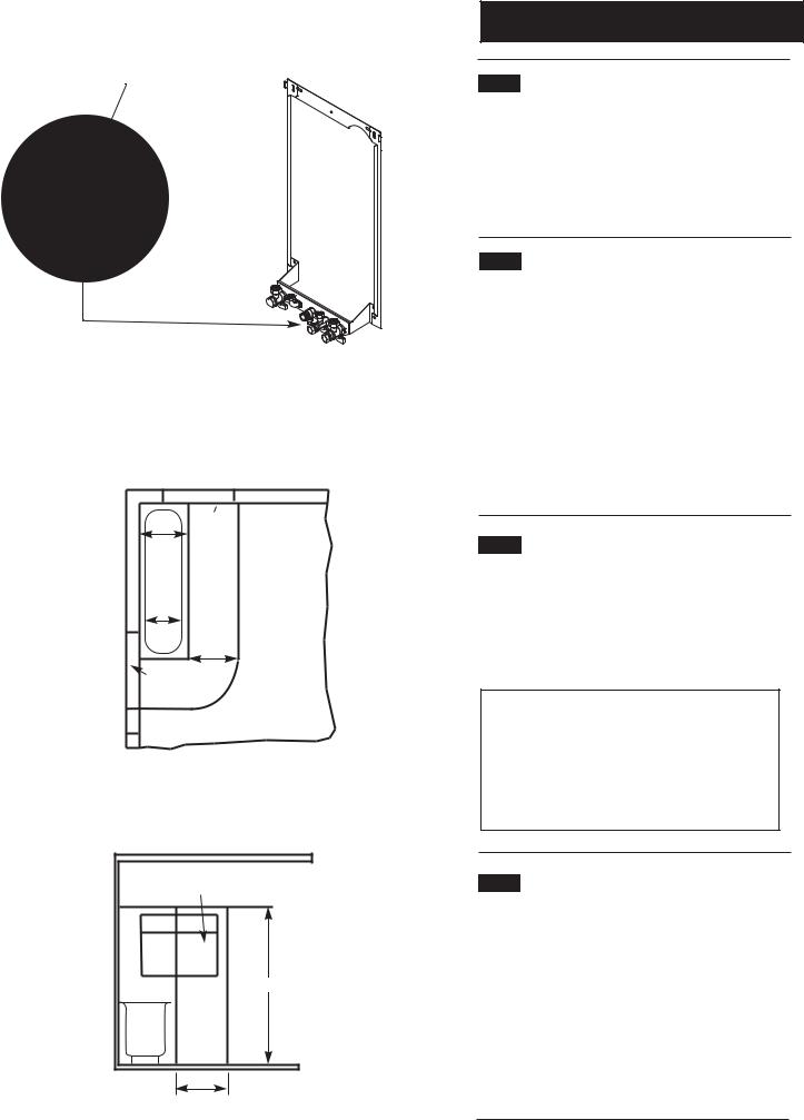
1. A flat vertical area is required for the installation of the boiler.
2. These dimensions include the necessary clearances around the boiler for case removal, spanner access and air movement. Additional clearances may be required for the passage of pipes around local obstructions such as joists running parallel to the front face of the boiler.
450mm Min
For Servicing
Purposes
5mm Min
In Operation
Fig. 9
© Baxi Heating UK Ltd 2013 |
15 |
Gas Service Cock
Fig. 10
Zone 2
Window
Recess
Zone 1
Zone 2
Zone 0
0.6 m
Window
Recess
Zone 2
Fig. A |
In GB Only |
|
|
|
Ceiling |
|
Window Recess |
|
|
Zone 2 |
Outside Zones |
|
|
|
Zone 1 |
Zone 2 |
2.25 m |
|
||
Zone 0 |
|
|
|
0.6 m |
|
Fig. B |
In GB Only |
7.0Site Requirement
7.3Ventilation of Compartments
1.Where the appliance is installed in a cupboard or compartment, no air vents are required.
2.BS 5440: Part 2 refers to room sealed appliances installed in compartments. The appliance will run sufficiently cool without ventilation.
7.4Gas Supply
1.The gas installation should be in accordance with the relevant standards. In GB this is BS 6891. In IE this is the current edition of I.S. 813 “Domestic Gas Installations”.
2.The connection to the appliance is a 22mm copper tail located at the rear of the gas service cock (Fig. 10).
3.Ensure that the pipework from the meter to the appliance is of adequate size, and the demands of any other gas appliances in the property are taken into consideration. Do not use pipes of a smaller diameter than the boiler gas connection (22mm).
7.5Electrical Supply
1.External wiring must be correctly earthed, polarised and in accordance with relevant regulations/rules. In GB this is the current I.E.E. Wiring Regulations. In IE reference should be made to the current edition of ETCI rules.
2.The mains supply is 230V ~ 50Hz fused at 3A.
NOTE: The method of connection to the electricity supply must facilitate complete electrical isolation of the appliance.
Connection may be via a fused double-pole isolator with a contact separation of at least 3mm in all poles and servicing the boiler and system controls only.
7.6Bath & Shower Rooms
1.If the boiler is fitted in a room containing a bath or shower and NOT FITTED with any optional integral timer or thermostat, it can be fitted in zone 2, (Figs. A & B shows zone dimensions for a bathtub. For other examples refer to the Current I.E.E. Wiring Regulations) reference must be made to the relevant requirements.
In GB this is the current I.E.E. Wiring Regulations and Building Regulations.
In IE reference should be made to the current edition of I.S.
813“Domestic Gas Installations” and the current ETCI rules.
16 © Baxi Heating UK Ltd 2013

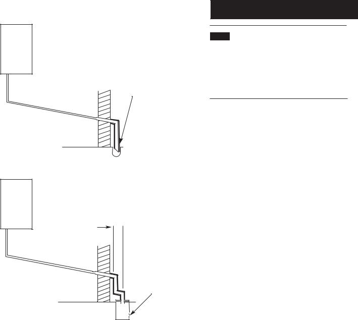
Examples are shown of the following methods of termination:-
i)to an internal soil & vent pipe
ii)via an internal discharge branch (e.g. sink waste) downstream of the trap
iii)to a drain or gully
iv)to a purpose made soakaway
v)pumped into an internal discharge branch (e.g. sink waste) downstream of the trap
vi)pumped into an external soil & vent pipe
vii)to a drain or gully with extended external run & trace heating
It is strongly recommended to discharge internally into the household drainage system. If connecting to a rain water drain, that drain MUST discharge into a foul drain.
21.5mm 32mm Insulation
i) Termination to an internal soil and vent pipe
|
50mm |
per |
|
|
|
|
|
|
|
|
|
|
|
|
|
|
|
|
|||
|
|
|
|
|
|
|
|
|
|
|
2. |
|
|
metre |
of pipe run |
|
|
||||
5° |
Minimum |
|
|
|
|
|
|
|
||
|
|
|
|
|
|
|
|
|
||
|
|
|
fall |
|
|
|
|
|
|
|
|
|
|
|
|
|
|
|
|
|
|
|
|
|
|
|
|
|
|
|
|
|
|
|
|
|
|
|
|
|
|
|
|
|
|
|
|
450mm min* |
|
|||||
|
|
|
|
|
||||||
|
|
|
|
|
|
|
|
|||
|
|
|
|
|
|
*450mm is applicable to |
||||
|
|
|
|
|
|
|||||
|
|
|
|
|
|
properties up to 3 storeys. |
||||
|
|
|
|
|
|
For multi-storey building |
||||
|
|
|
|
|
|
installations consult BS 6798. |
||||
|
ii) External termination via internal discharge branch |
Boiler |
e.g sink waste - downstream* |
|
Sink |
50mm |
per |
metre |
|
|
|
|
Pipe must terminate above |
|||||
|
|
|
|
|
||||||||||
|
|
|
|
|
|
|
|
|
|
|||||
|
|
|
|
|
|
|
|
|
|
|
||||
|
|
|
|
|
|
2. |
|
|
of pipe |
run |
|
water level but below |
||
|
|
|
|
|
|
|
|
|
|
|||||
|
|
|
|
|
|
5° |
Minimum |
fall |
|
|
|
|
surrounding surface. Cut |
|
|
|
|
|
|
|
|
|
|
|
|
|
|
end at 45° |
|
|
|
|
|
|
|
|
|
|
|
|
|
|
|
|
|
|
|
|
|
|
|
|
|
|
|
|
|
|
|
|
|
|
|
|
|
|
|
|
|
|
|
|
|
|
|
|
|
|
|
|
|
|
|
|
|
|
|
|
|
|
|
|
|
|
|
|
|
|
|
|
|
|
|
|
*It is NOT RECOMMENDED to connect upstream of the sink or other waste water receptacle !
7.0Site Requirements
7.7Condensate Drain
FAILURE TO INSTALL THE CONDENSATE DISCHARGE PIPEWORK CORRECTLY WILL AFFECT THE RELIABLE OPERATION OF THE BOILER.
CAREFUL CONSIDERATION MUST BE GIVEN TO THE POSSIBILITY OF THE PIPEWORK BEING SUBJECT TO FREEZING CONDITIONS AND APPROPRIATE MEASURES TAKEN TO PREVENT BLOCKAGE. CORRECT INSTALLATION IN ACCORDANCE WITH THIS SECTION WILL CONSIDERABLY MINIMISE THE LIKELIHOOD OF BLOCKAGE AND SUBSEQUENT BOILER LOCK-OUT.
A CONDENSATE DISCHARGE PUMP AND PIPE ‘TRACE HEATING’ ARE AVAILABLE AS ACCESSORIES - see paragraphs 7.7.12 to 7.715 for further details.
The condensate discharge pipe MUST NOT RISE at any point along its length. There MUST be a fall of AT LEAST 2.5° (50mm per metre) along the entire run EXCEPT when employing a suitable condensate pump in basement and cellar or similar applications.
The boiler condensate trap incorporates a seal of 75mm, therefore it is unnecessary to install an air break and trap in the discharge pipework.
1.The condensate outlet will accept 21.5mm (3/4in) plastic overflow pipe. It is strongly recommended that this discharges internally into the household drainage system. Where this is not possible, discharge into an outside drain is permissible providing every possible precaution is taken to prevent freezing.
2.Ensure the discharge of condensate complies with any national or local regulations in force. BS 6798 & Part H1 of the Building Regulations give further detailed guidance.
3.The discharge pipe should be run in a proprietary drain pipe material e.g. PVC, PVC-U, ABS, PVC-C or PP.
4.Metal pipework is NOT suitable for use in condensate discharge systems.
5.The pipe should be a minimum of 21.5mm diameter and must be supported using suitably spaced clips of the correct design to prevent sagging.
6.It is advisable that the full length of condensate pipe is run internally and preferably be less than 3 metres.
7.Internal runs greater than 3 metres or runs in cold areas should use 32mm waste pipe.
8.External runs MUST be a MINIMUM of 32mm and fully insulated with material suitable for external use.
9.If the boiler is fitted in an unheated location the entire condensate discharge pipe should be treated as an external run and sized and insulated accordingly.
10.In all cases discharge pipe must be installed to aid disposal of the condensate. To reduce the risk of condensate being trapped, as few bends and fittings as possible should be used and any burrs on cut pipe removed.
© Baxi Heating UK Ltd 2013 |
17 |
iii) Termination to a drain or gully
Boiler
Pipe must terminate above water level but below surrounding surface. Cut end at 45°
50mm |
per |
|
|
|
|
||
|
|
metre |
|
2. |
of pipe |
run |
|
|
|||
|
5° |
Minimum |
|
|
|
fall |
|
7.0Site Requirements
7.7Condensate Drain (cont.)
11.When discharging condensate into a soil stack or waste pipe the effects of existing plumbing must be considered. If soil pipes or waste pipes are subjected to internal pressure fluctuations when WC's are flushed or sinks emptied then back-pressure may force water out of the boiler trap and cause appliance lockout.
iv) Termination to a purpose made soakaway
Boiler Further specific requirements for soakaway design are referred to in BS 6798.
 500mm min
50mm per |
||
|
metre of |
|
2.5° |
pipe run |
|
Minimum fall |
||
|
||
Holes in the soak-away must face away from the building
18 © Baxi Heating UK Ltd 2013
 Loading...