


Please keep these instructions safe. Should you move house, please hand them over to the next occupier.
Baxi Combi 80Eco
Gas Fired Wall Mounted Combination Boiler
User’s Operating
Instructions

Natural Gas
Baxi Combi 80Eco
G.C.No 47 075 05
Baxi UK Limited is one of the leading manufacturers of domestic heating products in the UK.
Our first priority is to give a high quality service to our customers. Quality is designed into every Baxi product - products which fulfil the demands and needs of customers, offering choice, efficiency and reliability.
To keep ahead of changing trends, we have made a commitment to develop new ideas using the
latest technology - with the aim of continuing to make the products that customers want to buy.
Everyone who works at Baxi has a commitment to quality because we know that satisfied customers mean continued success.
We hope you get a satisfactory service from Baxi. If not, please let us know.
Baxi is a BS-EN ISO 9001
Accredited Company
Where fitted, user label for optional timer to be applied here.
The boiler meets the requirements of Statutory Instrument “ The Boiler (Efficiency) Regulations 1993 No 3083” and is deemed to meet the requirements of Directive 92/42/EEC on the energy efficiency requirements for new hot water boilers fired with liquid or gaseous fuels:-
Type test for purpose of Regulation 5 certified by: Notified Body 0051.
Product/Production certified by:
Notified Body 0051.
For GB/IE only.
2
STANDARD |
SCOPE |
|
|
B.S. 6891 |
Gas Installation. |
B.S. 5440: Pt 1 |
Flues. |
B.S. 5440: Pt 2 |
Air Supply. |
|
|
B.S. 5546 |
Installation of hot water supplies |
|
for domestic purposes. |
|
|
B.S. 7074 |
Expansion vessels and ancillary |
|
equipment for sealed water systems. |
|
|
B.S. 5449 |
Forced circulation hot water systems. |
B.S. 6798 |
Installation of gas fired hot water |
|
boilers. |
“Benchmark” Installation, Commissioning and Service
Record Log Book
Please ensure that your installer has completed the Installation and Commissioning sections of the Log Book and hands the Log Book over. The details of the Log Book will be required in the event of any warranty work. Keep the Log Book in a safe place and ensure that the relevant sections are completed at each subsequent regular service visit.
All CORGI registered installers carry a CORGI identification card and have a registration number. Both should be recorded in your boiler Log Book. You can check your installer is registered by telephoning 01256 372300 or writing to:-
1 Elmwood,
Chineham Business Park, Crockford Lane, Basingstoke,
RG24 8WG
IN AN EMERGENCY
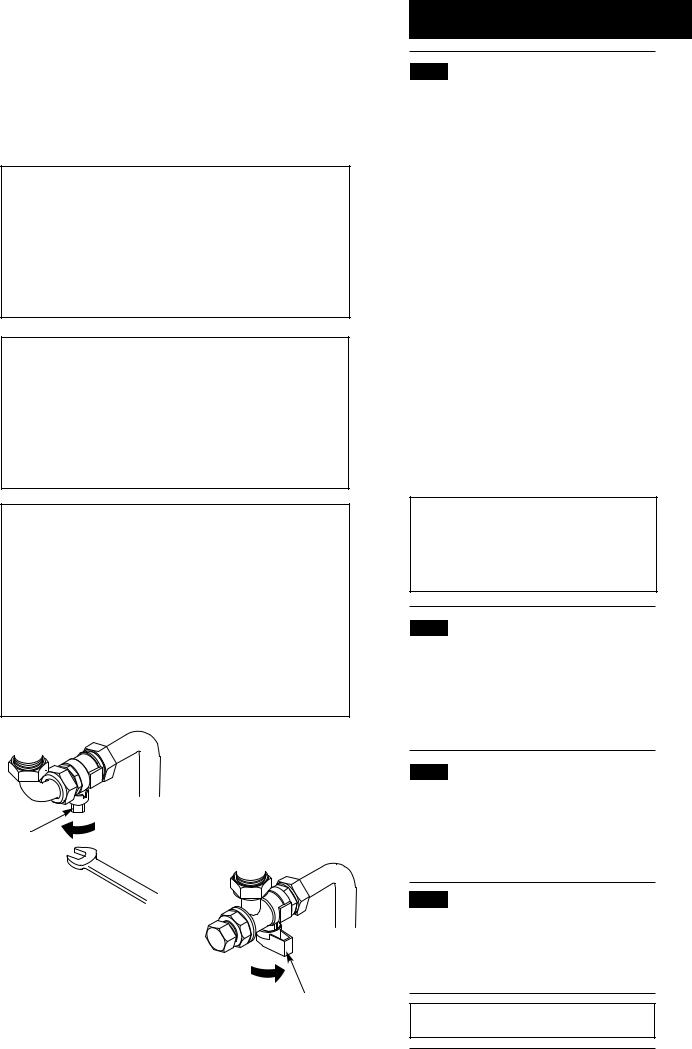
If a water or gas leak occurs or is suspected, the boiler can be isolated at the inlet valves as follows;
1.Turn off the electrical supply and turn the selector switch on the facia box to the OFF position.
2.Using a suitable open ended spanner or screwdriver turn the square on the gas tap to the left to isolate the gas supply at the boiler (Fig. 1).
3.The isolating valves are positioned under the boiler and can be closed by turning their taps to the right towards the wall (Fig. 2).
4.Call your Service Engineer as soon as possible.
Fig. 2
Gas Tap
Fig. 1
Heating Flow, Heating
Return and Mains
Water Inlet
Isolating Valves
1.0Warnings
1.1Safe Installation
1.The appliance is suitable for installation only in G.B. and I.E. and should be installed in accordance with the rules in force. For Ireland install in accordance with I.S.813 “INSTALLATION OF GAS APPLIANCES”. The installation must be
carried out by a CORGI Registered Installer or other registered competent person and be in accordance with the relevant requirements of GAS SAFETY (Installation and Use) REGULATIONS most recent edition, the BUILDING REGULATIONS issued by the Department of the Environment, BUILDING STANDARDS (Scotland) (Consolidation) REGULATIONS issued by the Scottish Development Department and the LOCAL BUILDING REGULATIONS. Where no specific instructions are given, reference should be made to the relevant
BRITISH STANDARD CODES OF PRACTICE and INSTALLATION SPECIFICATIONS.
2.This appliance must be installed in accordance with the manufacturer’s instructions and the rules in force, and only used in a suitably ventilated location.
3.Read the instructions before installing or using this appliance.
4.Any purpose provided ventilation should be checked periodically to ensure that it is free from obstruction.
IMPORTANT - The addition of anything that may interfere with the normal operation of the appliance without the express written permission of Baxi UK Limited could invalidate the appliance warranty and infringe the GAS SAFETY (Installation and Use) REGULATIONS.
1.2In case of gas leaks
1.If a gas leak is found or suspected, turn off the gas supply at the meter immediately and at the isolating valve on the boiler if possible. Contact your Installer or Transco (under 'Gas' in the phone directory).
1.3Servicing your Appliance
1. For reasons of safety and economy your appliance should be serviced annually. Servicing must be performed by a competent person. Your Installer or British Gas Service will be able to advise you.
1.4Electricity Supply
1.THIS APPLIANCE MUST BE EARTHED.
2.A standard 230V ~ 50Hz supply is required. The appliance must be protected by a 3 amp fuse.
Never Hang Flammable Items Over The
Appliance
3

1.On/Off/Reset Selector Switch
2.Burner On Neon
3.Power On Neon
4.Flame Failure Neon
5.Central Heating Temperature Control
6.Hot Water Temperature Control
7.Central Heating System Pressure Gauge
8.Optional Integral Timer Position
1 |
2 |
3 |
4 |
5 |
6 |
Fig. 4
Position (i)
(Central Heating or Hot Water)
Fig. 6
Fig. 7
Position (ii)
(Hot Water)
2
1 |
3 |
0 |
4 |
bar
Fig. 3
|
2 |
1 |
3 |
0 |
4 |
7 |
8 |
Fig. 5
OFF Position
2.0Operating the Boiler
2.1Introduction
1.Your Baxi Combi 80Eco is a gas fired, room sealed, powered flue combination boiler, providing central heating for your home and mains fed domestic hot water to taps and shower. It is fully automatic and does not have a pilot light.
2.Priority is given to the hot water mode - when a hot water tap is turned on the supply of heat to the central heating circuit is interrupted.
2.2Operating the Boiler
1.Ensure that the electricity and gas supplies are turned on. Check that the central heating pressure is between 0.5 and 1.0 bar (Fig. 3).
2.Turn the On/Off/Reset selector switch either anti-clockwise from the off position (Fig. 5) to both central heating and domestic hot water or clockwise to domestic hot water only.
3.In either position the green power on neon
( ) will illuminate (Fig. 4).
4.Position (i) In this position the central heating will operate according to demand or provide domestic hot water when a tap or shower is turned on (Fig. 6). Priority is given to domestic hot water.
5.Position (ii) In this position hot water will be provided when a tap or shower is turned on (Fig. 7).
6.The boiler will light automatically on demand.
7.The orange burner on neon (  ) will illuminate when the boiler is operating and the main burner is
on (Fig. 4).
IMPORTANT: When the selector switch is in the ‘0’ (Off) position the electrical supply to the boiler is isolated. The boiler will not operate and the integral timer (if fitted) will require resetting once the selector switch is set to either the Position (i) or Position (ii).
4
 Loading...