


Baxi ECO5 Compact 14 F, ECO5 Compact 1.24 F, ECO5 Compact 24, ECO-5 Compact 24 F, ECO5 Compact 18 F User Manual [ru]
...
it |
CALDAIA MURALE A GAS AD ALTO RENDIMENTO |
|
Manuale per l’uso destinato all’utente ed all’installatore |
en |
HIGH PERFORMANCE GAS-FIRED WALL-MOUNTED BOILER |
|
Operating and installation instructions |
ru ВЫСОКОПРОИЗВОДИТЕЛЬНЫЙ НАСТЕННЫЙ ГАЗОВЫЙ КОТЕЛ |
|
|
Руководство по установке и эксплуатации |
es |
CALDERA MURAL DE GAS DE ALTO RENDIMIENTO |
|
Manual para el usuario y el instalador |
hu |
MAGAS HOZAMÚ FALI GÁZKAZÁN |
|
Felhasználói és szerelői kézikönyv |
cs |
PLYNOVÝ ZÁVĚSNÝ KOTEL S VYSOKOU ÚČINNOSTÍ |
|
Návod na použití určený pro uživatele a instalatéra |
sk |
PLYNOVÝ ZÁVESNÝ KOTOL S VYSOKOU ÚČINNOSŤOU |
|
Návod na použitie určený pre používateľa a inštalatéra |
fr |
CHAUDIERE MURALE A GAZ A HAUT RENDEMENT |
|
Notice d’emploi et d’installation destinée à l’utilisateur et à l’installateur |
ro CENTRALĂ TERMICĂ MURALĂ PE GAZ CU RANDAMENT RIDICAT |
|
|
Manual de instrucţiuni pentru utilizator şi instalator |

Dear Customer,
Our company is conident our new product will meet all your requirements. Buying one of our products guarantees all your expectations: good performance combined with simple and rational use.
Please do not put this booklet away without reading it irst: it contains useful information for the correct and eficient use of your product.
Our company declares that these products are marked  in compliance with the essential requirements of the following Directives:
-Gas Directive 2009/142/EC
-Eficiency Directive 92/42/EEC
-Electromagnetic Compatibility Directive 2004/108/EC
-Low Voltage Directive 2006/95/EC
Use r & Installe r (en)
Our company, constantly striving to improve the products, reserves the right to modify the details given in this documentation at any time and without notice. These Instructions are only meant to provide consumers with use information and under no circumstance should they be construed as a contract with a third party.
CONTENT |
|
|
|
DESCRIPTION OF SYMBOLS ..................................................................................................................................................................... |
25 |
|
SAFETY WARNINGS.................................................................................................................................................................................... |
25 |
|
GENERAL PRECAUTIONS ......................................................................................................................................................................... |
26 |
|
ENERGY-SAVING TIPS................................................................................................................................................................................ |
26 |
1. |
COMMISSIONING THE BOILER.................................................................................................................................................................. |
27 |
1.1 |
ADJUSTING THE CH AND DHW FLOW TEMPERATURE .......................................................................................................................... |
27 |
2. |
OPERATING MODES ................................................................................................................................................................................... |
28 |
3. |
FILLING THE SYSTEM................................................................................................................................................................................. |
28 |
4. |
SWITCHING OFF THE BOILER ................................................................................................................................................................... |
28 |
5. |
GAS CONVERSION ..................................................................................................................................................................................... |
28 |
6. |
PROLONGED SHUTDOWN. ANTI-FREEZE PROTECTION ....................................................................................................................... |
28 |
7. |
FAULTS......................................................................................................................................................................................................... |
29 |
8. |
ROUTINE MAINTENANCE INSTRUCTIONS............................................................................................................................................... |
29 |
|
INSTRUCTIONS PRIOR TO INSTALLATION............................................................................................................................................... |
30 |
9. |
INSTALLING THE BOILER ........................................................................................................................................................................... |
30 |
10. |
INSTALLING THE DUCTS ............................................................................................................................................................................ |
30 |
10.1 |
CONCENTRIC DUCTS................................................................................................................................................................................. |
31 |
10.2 |
SEPARATE DUCTS ...................................................................................................................................................................................... |
31 |
11. |
ELECTRICAL CONNECTIONS..................................................................................................................................................................... |
32 |
11.1 |
CONNECTING THE ROOM THERMOSTAT................................................................................................................................................. |
33 |
11.2 |
ACCESSORIES NOT INCLUDED IN THE SUPPLY..................................................................................................................................... |
33 |
12. |
GAS VALVE................................................................................................................................................................................................... |
34 |
12.1 |
GASCONVERSION ...................................................................................................................................................................................... |
34 |
12.2 |
REPLACING THE GAS VALVE..................................................................................................................................................................... |
35 |
12.3 |
GAS VALVE CALIBRATION.......................................................................................................................................................................... |
35 |
12.4 |
REPLACING THE ELECTRONIC BOARD ................................................................................................................................................... |
36 |
13. |
VISUALISATION OF PARAMETERS ON THE DISPLAY (“INFO” FUNCTION) ........................................................................................... |
36 |
14. |
PARAMETER SETTINGS ............................................................................................................................................................................. |
37 |
15. |
TROUBLESHOOTING SERVICE FAULTS ................................................................................................................................................... |
38 |
16. |
ADJUSTMENT AND SAFETY DEVICES ...................................................................................................................................................... |
41 |
17. |
PUMP CAPACITY/ HEAD ............................................................................................................................................................................. |
41 |
18. |
ANNUAL SERVICING ................................................................................................................................................................................... |
42 |
18.1 |
HYDRAULIC UNIT ........................................................................................................................................................................................ |
42 |
18.2 |
POSITIONING THE ELECTRODE................................................................................................................................................................ |
42 |
18.3 |
CLEANING THE FILTERS ............................................................................................................................................................................ |
42 |
18.4 |
REMOVING SCALE FROM THE D.H.W. CIRCUIT ...................................................................................................................................... |
43 |
18.5 |
DISMOUNTING THE WATER-WATER HEAT EXCHANGER ....................................................................................................................... |
43 |
19. |
COMBUSTION PARAMETERS .................................................................................................................................................................... |
43 |
20. |
TECHNICAL SPECIFICATIONS ................................................................................................................................................................... |
44 |
7110102.03 (1-06/13) |
24 |
DESCRIPTION OF SYMBOLS
WARNING
Risk of damage to or malfunction of the appliance. Pay special attention to the warnings concerning danger to people.
DANGER OF BURNS
Wait for the appliance to cool down before working on the parts exposed to heat.
DANGER - HIGH VOLTAGE
Live components - electrocution hazard.
DANGER OF FREEZING
Possible formation of ice due to low temperatures.
FIRE HAZARD
Potentially lammable material or gas.
IMPORTANT INFORMATION
Information to read with particular care as it is useful for the correct operation of the boiler.
GENERIC PROHIBITION
It is forbidden to do/use the things indicated alongside the symbol.
SAFETY WARNINGS
SMELL OF GAS
•Switch off the boiler.
•Do not activate any electrical device (such as switching on the light).
•Put out any naked lames and open the windows.
•Call an Authorised Service Centre.
SMELL OF COMBUSTION FUMES
•Switch off the boiler.
•Open all the doors and windows to ventilate the room.
•Call an Authorised Service Centre.
FLAMMABLE MATERIAL
Do not use and/or store highly lammable material (thinners, paper, etc.) near the boiler.
SERVICING AND CLEANING THE BOILER
Switch off the boiler before working on it.
Do not leave any packaging (plastic bags, polystyrene, etc.) within the reach of children as they are a potential source of danger.
The appliance is not intended to be used by persons with reduced physical, sensory or mental capacities, or who lack experience or knowledge, unless, through the mediation of a person responsible for their safety, theyhave had the beneit
of supervision or of instructions on the use of the appliance.
BAXI a leading European manufacturer of hi-tech boilers and heating systems, has developed
CSQ-certiied quality management (ISO 9001), environmental (ISO 14001) and health and safety (OHSAS 18001) systems. This means that BAXI S.p.A. includes among its objectives the safeguarding of the environment, the reliability and quality of its products, and the health and safety of its employees.
Through its organisation, the company is constantly committed to implementing and improving these aspects in favour of customer satisfaction.
(en) r Installe & r Use
25 |
7110102.03 (1-06/13) |

Use r & Installe r (en)
GENERAL PRECAUTIONS
This boiler has been designed to heat water to a temperature lower than boiling point at atmospheric pressure. It must be connected to a central heating system and to a domestic hot water supply system according to its performance and power output. Before having the boiler installed by a qualiied service engineer, make sure the following operations are performed:
•Make sure that the boiler is adjusted to use the type of gas delivered by the gas supply. To do this, check the markings on the packaging and the rating plate on the appliance.
•Make sure that the lue terminal draft is appropriate, that the terminal is not obstructed and that no exhaust gases from other appliances are expelled through the same lue duct, unless the latter has been specially designed to collect exhaust gas from more than one appliance, in compliance with current laws and regulations.
•Make sure that, if the boiler is connected to existing lue ducts, these have been thoroughly cleaned as residual products of combustion may detach from the walls during operation and obstruct the low of fumes.
•To ensure correct operation and maintain the warranty, observe the following precautions:
1. DHW circuit
1.1If the water is harder than 20 °F (1 °F = 10 mg calcium carbonate per litre of water), install a polyphosphate dispenser or an equivalent treatment system, compliant with current regulations.
1.2Thoroughly lush the system after installation of the appliance and before use.
1.3The materials used for the DHW circuit comply with Directive 98/83/EC.
2. Heating circuit
2.1 New system: Before installing the boiler, the system must be cleaned and lushed to eliminate residual thread-cutting swarf, solder and any solvents, using suitable off-the-shelf non-acid and non-alkaline products that do not damage metal, plastic and
rubber parts. To protect the system from scale, use inhibitors such as SENTINEL X100 and FERNOX protector for heating circuits.
Use these products in strict compliance with the manufacturers' inst ructions.
2.2 Existing system: Before installing the boiler, drain the system and clean it to remove sludge and contaminants, using suitable
proprietary products. Recommended cleaning products are: SENTINEL X300 or X400 and FERNOX regenerator for heating circuits. Use these products in strict compliance with the manufacturers' instructions. Remember that the presence of foreign bodies in the heating system can adversely affect boiler operation (e.g. overheating and excessive noise of the heat exchanger).
Initial lighting of the boiler must be carried out by an authorised Service Engineer who must irst ensure that:
•The rated data correspond to the supply (electricity, water and gas) data.
•That the installation complies with current regulations.
•The appliance is correctly connected to the power supply and earthed.
Failure to observe the above will render the warranty null and void. The names of the authorised Service Centres are indicated in the attached sheet. Prior to commissioning, remove the protective plastic coating from the boiler. Do not use any tools or
abrasive detergents to do this as you may damage the painted surfaces.
ENERGY-SAVING TIPS
Adjustment in the heating mode
Adjust the boiler low temperature depending on the kind of system. For systems with radiators, set a maximum heating water low temperature of approximately 60°C, and increase this value if the required room temperature is not reached. For systems with radiant loor panels, do not exceed the temperature indicated by the system designer. Use the External Sensor and/or Control Panel to automatically adjust the low temperature to atmospheric conditions or the indoor temperature. This ensures that no more heat than that effectively necessary is produced. Adjust the room temperature without overheating the rooms. Every extra degree centigrade means consuming approximately 6% more. Also room ambient temperature depending on how the rooms are used. For example, the bedroom or the least used rooms can be heated to a lower temperature. Use the programmable timer and set the night-time room temperature at approximately 5°C lower than that during the day. There is no appreciable saving to be achieved by setting it any lower. Only in case of a prolonged absence, such as a holiday, should the temperature setpoint be lowered. Do not cover radiators as this prevents the air from circulating correctly. Do not leave the windows partially open to ventilate the rooms
but open them completely for a short period.
Domestic hot water
Setting the domestic hot water at the required temperature without mixing it with cold water saves a lot of money. Additional heating wastes energy and creates additional scale.
7110102.03 (1-06/13) |
26 |
1. COMMISSIONING THE BOILER
To light the boiler correctly, proceed as follows:
•Open the gas tap (normally positioned under the boiler);
•Check that the hydraulic pressure in the system is correct ("FILLING THE SYSTEM" section);
•power the boiler;
•press button  and switch the boiler to Summer
  or Winter
 ;
;
•press buttons 
 and
and 
 to adjust the temperature of the heating circuit
  and domestic hot water circuit
  in order to ignite the main burner.
When the boiler is lit, the symbol |
will appear on the display. |
|
In the Summer position |
the main burner will only ignite if a DHW tap is opened. |
|
During initial ignition, the burner may not ignite (causing the boiler to shut down) until any air in the gas pipes is vented. In this case, repeat the ignition procedure until gas reaches the burner. Press button  for at least 2 seconds.
Key to SYMBOLS
Operation in the heating mode
Flame present (burner on)
No lame (ignition failure)
Operation in the DHW mode
Generic fault
Resettable fault
No water (low system pressure)
Numerical signal (temperature, code, fault, etc.)
Key to BUTTONS
|
On / Off / Summer / Winter |
|
Reset |
|
|
|
|
|
CH temperature adjustment |
|
Information |
|
|
|
|
|
DHW temperature adjustment |
|
|
|
|
|
|
1.1 ADJUSTING THE CH AND DHW FLOW TEMPERATURE
The system must be itted with an ambient thermostat for controlling indoor temperature.
Adjust the CH |
and DHW |
delivery temperature by pressing buttons |
and |
respectively. When the burner is |
|
lit, the display shows the symbol . |
|
|
|
||
HEATING: while the boiler is operating in the heating mode, the display shows the lashing symbol |
and the heating delivery |
||||
temperature (°C). |
|
|
|
|
|
DHW: while the boiler is operating in the DHW mode, the display shows the lashing symbol |
and the DHW outlet temperature |
||||
(°C). |
|
|
|
|
|
(en) n Sectio R USE
27 |
7110102.03 (1-06/13) |
USE R Sectio n (en)
2. OPERATING MODES
 Press this button to set the following operating modes:
•SUMMER
•WINTER
•OFF
In the SUMMER mode, the display shows  . The boiler satisies requests for DHW only while central heating is not enabled
(ambient frost protection function active).
In the WINTER mode, the display shows 
 . The boiler satisies requests for both DHW and central heating (ambient frost
protection function active).
In the OFF mode, the display shows neither of the above two symbols . In this mode, only the ambient frost protection function is active while requests for DHW and central heatingare not satisied.
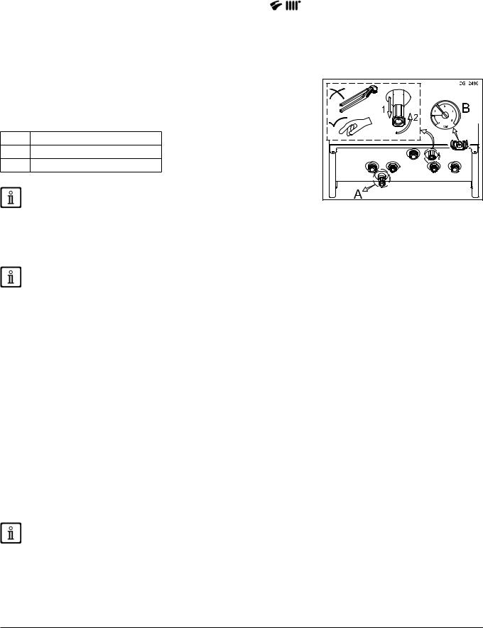
3. FILLING THE SYSTEM
Disconnect the boiler from the mains power supply using the two-pole switch.
Regularly check that the pressure displayed on the pressure gauge B is 1 - 1.5 bar, with the boiler cold. If the pressure is too low, turn tap C to ill the boiler.
In case of overpressure, open the boiler drain valve A.
ASystem drain tap
BPressure gauge
CSystem illing tap
Take special care when illing the heating system. In particular, open any thermostat valves in the system, ensure the water enters slowly in order to
prevent the formation of air inside the primary circuit until operating pressure is reached. Lastly, vent any radiators in the syste m. Our company declines all
C |
a |
|
liability for damage deriving from the presence of air bubbles in the primary exchanger due to the incorrect or imprecise observance of the above.
The boiler is itted with a hydraulic pressure gauge which prevents the boiler from working if there is no water.
If pressure drops occur frequently, have the boiler checked by the AUTHORISED TECHNICAL SERVICE CENTRE.
4. SWITCHING OFF THE BOILER
To turn off the boiler, disconnect the electric power supply. In the "OFF" mode the boiler remains off (the display indicates OFF) though the electrical circuits remain live and the frost protection device is enabled.
5. GAS CONVERSION
The boilers can operate both on natural gas (G20) and LPG (G31). All gas conversions must be made by the AUTHORISED TECHNICAL SERVICE CENTRE.
6. PROLONGED SHUTDOWN. ANTI-FREEZE PROTECTION
Do not drain the whole system as illing up with water again could cause unnecessary and harmful scale to build up inside the boiler and the heating elements. If the boiler is not used during winter and is therefore exposed to the danger of frost, add some speciic anti-freeze to the water in the system (e.g.: propylene glycol coupled with corrosion and scale inhibitors). The electronic boiler management system includes a “frost protection” function for the heating system which, when delivery temperature falls below 5°C, lights the burner until a delivery temperature of 30°C is reached.
The function is operative if: the boiler is electrically powered, there is gas, system pressure is normal and the boiler is not blocked.
7110102.03 (1-06/13) |
28 |

7. FAULTS
The faults shown |
on the |
display are identiied with thel"E"symboand a number (fault code). For a |
|||
complete list of faults, see the following table. |
|
|
|||
If "R" appears on the display the fault must be RESET by the user. |
|
|
|||
To reset, press and hold down |
for at least 2 seconds. If this fault persists, call the Authorised Service |
||||
Centre. |
|
|
|
|
|
FAULTS TABLE |
|
|
|
|
|
|
|
|
|
|
|
CODE DISPLAYED |
|
FAULT |
|
ACTION |
|
|
|
|
|
||
E01 |
Failed ignition shutdown. |
Press and hold down |
for at least 2 seconds. |
||
E02 |
Shut down by safety thermostat. |
Press and hold down |
for at least 2 seconds. |
||
E03 |
Board coniguration error |
Call the Authorised Service Centre. |
|||
|
|
|
|
||
E04 |
Safety error due to ignition failure/frequent lame |
Press and hold down for at least 2 seconds. |
|||
loss. |
|
||||
|
|
|
|
||
E05 |
Flow sensor failure. |
Call the Authorised Service Centre. |
|||
|
|
|
|||
E06 |
DHW sensor fault. |
Call the Authorised Service Centre. |
|||
|
|
|
|||
E07 |
Fumes NTC probe fault. |
Press and hold down for at least 2 seconds. |
|||
E08 |
Error in the lame ampliication circuit. |
Call the Authorised Service Centre. |
|||
|
|
|
|||
E09 |
Error in the gas valve safety circuit. |
Call the Authorised Service Centre. |
|||
|
|
|
|
||
E10 |
No hydraulic pressure switch enable. |
Check that the pressure in the system is correct; See the FILLING |
|||
THE SYSTEM section. |
|
||||
|
|
|
|
||
E22 |
Switching off due to power supply reductions. |
Automatic reset at voltages in excess of 170V. If this fault |
|||
persists, call the Authorised Service Centre. |
|||||
|
|
|
|||
E25 |
No water safety trip (pump probably blocked). |
Press and hold down |
for at least 2 seconds. |
||
E26 |
Heating circuit overheated/ no water safety trip |
If this fault persists, call the Authorised Service Centre. |
|||
(pump probably blocked). |
|||||
|
|
|
|||
E35 |
Parasite lame (lame error). |
If this fault persists, call the Authorised Service Centre. |
|||
|
|
|
|||
E36 |
Fumes NTC probe fault. |
Call the Authorised Service Centre. |
|||
|
|
|
|
||
E40 - E41 |
Shutdown due to probable obstruction of air/lue |
Press and hold down for at least 2 seconds. |
|||
duct or insuficient gas inlet pressure. |
|||||
|
|
|
|||
E42 |
Flame loss (air/lue duct may be totally obstructed or |
Press and hold down |
for at least 2 seconds. |
||
|
fan may be faulty). |
|
|
||
E43 |
Shutdown due to probable obstruction of air/lue |
Temporary fault. Automatic reset at voltages in excess of 185V or |
|||
duct or insuficient gas inlet pressure. |
press for at least 2 seconds. |
||||
|
|||||
E50 |
Shutdown due to fumes NTC probe tripping for |
Press and hold down for at least 2 seconds. |
|||
overheating. |
|||||
|
|
|
|||
E55 |
Gas valve not electronically calibrated. |
Call the Authorised Service Centre. |
|||
|
|
|
|
||
E62 |
Safety shutdown if the lame signal or fumes |
Press and hold down for at least 2 seconds. |
|||
temperature fail to stabilise |
|||||
|
|
|
|||
E65 |
Safety shutdown if the air/lue duct obstruction test |
Press and hold down for at least 2 seconds. |
|||
fails frequently. |
|||||
|
|
|
|||
E98 |
Electronic board parameters incorrectly conigured. |
Call the Authorised Service Centre. |
|||
|
|
|
|||
|
Boiler operating at reduced power. Air/lue duct may |
Temporarily eliminate the current heat request to reset the fault. If |
|||
Flashing lights |
be obstructed or gas inlet pressure may be too low. |
this fault persists, call the Authorised Service Centre. |
|||
|
|
|
|
||
|
|
|
|
|
|
In case of a fault, the display backlighting lashes together with the error code.
If a fault code is displayed that is not included in the list or if a certain fault occurs frequently, contact the AUTHORISED TECHNICAL SERVICE CENTRE.
(en) n Sectio R USE
8. ROUTINE MAINTENANCE INSTRUCTIONS
To keep the boiler eficient and safe, have it checked by the Authorised Service Centre at the end of every operating period.
Careful servicing ensures economical operation of the system.
29 |
7110102.03 (1-06/13) |

INSTALLE R Sectio n (en)
INSTRUCTIONS PRIOR TO INSTALLATION
The following notes and technical instructions are addressed to installers to allow them to carry out trouble-free installation.
Instructions for igniting and using the boiler are contained in the ‘Instructions for Users’ section. The installation must satisfy the requirements of local by-laws and technical regulations.
Moreover, the installation technician must be qualiied to install heating appliances. Additionally, bear in mind thefollowing:
•This boiler can be connected to any type of doubleor single-pipe convector plate, radiator or fancoil unit. Design the system sections as usual, though, bearing in mind the available capacity-head at the plate (see "SECTION" E at the end of this manual).
•Initial ignition of the boiler must be carried out by the Authorised Service Centre, as indicated on the attached sheet.
ADDITIONAL PUMP WARNING: If an additional pump is used on the heating system, a suitably sized hydraulic separator must be installed downline from the boiler. This will allow the water pressure switch on the boiler to operate correctly.
SOLAR CIRCUIT WARNING: if the instantaneous (mixed) boiler is connected to a systemthwisolar panels, the maximum temperature of the domestic hot water entering the boiler mustnot exceed 60°C.
TEMPERATURE ADJUSTMENT ON LOW TEMPERATURE HEATING SYSTEM: for a low temperature system (such as underloor heating), reduce the maximum CH temperature setpointtheonboiler to 45°C) by modifying parameter F06=001 as
described in the SETTING PARAMETERS section.
Failure to observe the above will render the warranty null and void.
Do not leave any packaging (plastic bags, polystyrene, etc.) within the reach of children as they are a potential source of danger.
9. INSTALLING THE BOILER
The template outline is shown in "SECTION C" at the end of this manual.
After deciding the exact location of the boiler, ix the template to the wall. Connect the system to the gas and water inlets present on the lower bar of the template. Fit two G3/4 taps (low and return) on the central heating circuit; these taps make it possible to carry out important operations on the system without draining it completely. If you are either installing the boiler on an existing system or replacing one, as well as the above, it a settling tank under the boiler on the system return line in order to collect any deposits and scale circulating in the system after lushing. After ixing the boiler to the template, connect the lue and air ducts, supplied as accessories, as described in the following sections.
Tighten the boiler water connections with care (maximum tightening torque 30 Nm).
10.INSTALLING THE DUCTS
The boiler is easy and lexible to install thanks to the extensive range of available accessories, as described below. The boiler has been designed for connection to a vertical or horizontal coaxial lue-air duct. The boiler can also be used with separate ducts using
the accessory splitting kit.
For optimal installation, the accessories supplied by the manufacturer should be used.
To optimise operating safety, make sure the lue ducts are irmly ixed to the wall with suitable brackets. The brackets must be positioned over the joints at a distance of approximately 1 metre from one another.
SOME OUTLET DUCT INSTALLATION EXAMPLES AND THEIR RELATIVE MAXIMUM
LENGTHS ARE SHOWN IN ANNEX "SECTION" D AT THE END OF THIS MANUAL.
7110102.03 (1-06/13) |
30 |
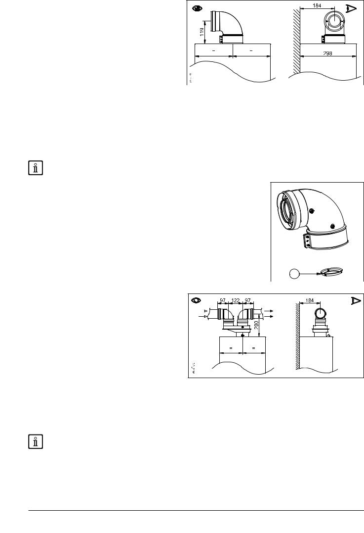
10.1 CONCENTRIC DUCTS
This type of duct is used to discharge exhaust fumes and draw combustion air both outside the building and if a LAS lue is itted. The 90° coaxial bend allows the boiler to be connected to a lue-air duct in any direction as it can be rotated by 360° It can also be used as a supplementary curve combined with a coaxial duct or a 45° curve.
If fumes are discharged outside the building, the lue-air duct must protrude at least 18 mm from the wall to allow an aluminium weathering surround to be itted and sealed to avoid water iniltrations.
•A 90° bend reduces the total duct length by 1 metre.
•A 45° bend reduces the total duct length by 0.5 metres.
•The irst 90° bend is not included when calculating the maximum available length.
Secure the intake pipes with two galvanised screws with a diameter of 4.2 mm and a maximum length of 19 mm.
Before securing the screws, make sure that at least 45 mm of the pipe is inserted into the gasket (see the igures in "SECTION"
D at the end of this manual).
Make sure there is a minimum downward slope towards the outside of 1 cm per metre of duct length.
Measure the diaphragm with the gauge.
MODEL |
Length (m) |
Using a DIAPHRAGM on |
|
OUTLET DUCT (mm) “A” |
|||
|
|
||
|
0 ÷ 1 |
Ø 43 |
|
1.24 F - 24 F |
|
|
|
1 ÷ 2 |
Ø 45 |
||
|
|
|
|
|
2 ÷ 5 |
No |
|
|
|
|
|
18 F |
0 ÷ 1 |
Ø 41 |
|
|
|
||
1 ÷ 2 |
Ø 43 |
||
1.14 F - 14 F |
|||
|
|
||
2 ÷ 5 |
Ø 45 |
||
|
|||
|
|
|
A |
CG 2117 |
|
10.2 SEPARATE DUCTS
This type of installation makes it possible to discharge  exhaust fumes both outside the building and into single lu ducts. Comburent air can be drawn in at a different location
 from that of the lue terminal.
  The optional splitting accessory is ixed to the boiler turret
(Ø 100/60 mm) and allows the air and fumes to enter/leave the two separate ducts (Ø 80 mm). For further information, read the assembly instructions supplied with the accessory.
The 90° bend is used to connect the boiler to theandinlet
outlet ducts, adapting them to various requirements. It can also be used as a supplementary curve combined with a duct or a 45° bend.
•A 90° bend reduces the total duct length by 0,5 metres.
•A 45° bend reduces the total duct length by 0,25 metres.
•The irst 90° bend is not included when calculating the maximum available length.
Make sure there is a minimum downward slope towards the outside of 1 cm per metre of duct length. In the event of installation of the condensate collection kit, the angle of the drain duct must be directed towards the boiler.
Measure the diaphragm with the gauge.
(en) n Sectio R INSTALLE
31 |
7110102.03 (1-06/13) |

INSTALLE R Sectio n (en)
MODEL |
Length (m) |
Using a DIAPHRAGM on |
||
(L1 |
+ L2) |
OUTLET DUCT (mm) “A” |
||
|
||||
|
|
|
|
|
|
0 |
÷ 4 |
Ø 43 |
|
|
|
|
||
1.24 F - 24 F |
4 ÷ 10 |
Ø 45 |
||
|
|
|
||
10 |
÷ 20 |
Ø 47 |
||
|
||||
|
|
|
|
|
|
20 |
÷ 30 |
No |
|
|
|
|
|
|
MODEL |
Length (m) |
Using a DIAPHRAGM on |
|
(L1 + L2) |
OUTLET DUCT (mm) “A” |
||
|
|||
|
|
|
|
18 F |
0 ÷ 15 |
Ø 41 |
|
|
|
||
15 ÷ 25 |
Ø 43 |
||
1.14 F - 14 F |
|||
|
|
||
25 ÷ 30 |
Ø 45 |
||
|
|||
|
|
|
For the C52 type, do not it the lue and air duct terminals on opposite walls of the building.
If the discharge duct is longer than 6 metres, install the condensate collection kit, supplied as an accessory, near the boiler.
If itting a single lue duct, make sure it is adequately insulated (e.g.: with glass wool) wherever the duct passes through building walls. For detailed installation instructions, consult the technical data provided with the accessories.
10.2.1 NOTES FOR INSTALLATIONS WITH SEPARATE OUTLETS
In particular installation situations with separate ducts,
vibrations may be generated in the appliance.
To solve this problems, a slot closed with pre-punched holes
on the outlet (Ref. A) has been prepared on the fumes outlet. This can be easily removed by the Qualiied Technical Assistance Service without having to remove the outlet. Remove knock-out A andchecktheapplianceworkscorrectly.
11.ELECTRICAL CONNECTIONS
Thismachineisonlyelectricallysafeifitiscorrectlyconnectedt
regulations.
Connecttheboilertoa230Vsingle-phaseearthedpowersupp
NEUTRAL polarity.
Use a double-pole switch with a contact separation of at least 3 mm.
When replacing the power supply cable, it a harmonised "HAR H05 W-F" 3x0.75mm2 cable with a maximum diameter of 8 mm.
Access to the power supply terminal block
•remove the front panel of the boiler (secured at the bottom with two screws);
•turn the control box downwards;
•remove the metal guard from the control box;
•open the left-hand side of the cover and access the electrical connections area.
The 2A fast-blowing fuse is incorporated in the power supply terminal block (to check and/or replace the fuse, pull out the black fuse carrier).
The terminal block is at high voltage. Before making connections, make sure the appliance is disconnected from the power supply.
Respect polarity L (LIVE) - N (NEUTRAL).
(L) = Live (brown)
(N) = Neutral (light blue).
 = Earth (yellow-green).
(1) (2) = contact for Room Thermostat.
7110102.03 (1-06/13) |
32 |
|
11.1 CONNECTING THE ROOM THERMOSTAT
To connect the Room Thermostat to the boiler, proceed as follows:
•access the power terminal block as described in the ELECTRICAL CONNECTIONS section;
•remove the jumper on terminals (1) and (2);
•thread the two-wire cable through the grommet and connect it to these two terminals.
11.2 ACCESSORIES NOT INCLUDED IN THE SUPPLY
11.2.1 CONNECTING THE EXTERNAL PROBE
To connect the External Probe, supplied as an accessory, to the boiler, proceed as follows:
•access the power terminal block as described in the ELECTRICAL CONNECTIONS section;
•for heating and DHW models: connect the external probe to the two RED wires itted with faston covers;
•for heating only models: connect the external probe to the M2 terminal block, see the wiring diagrams in annex "SECTION" B at the end of this manual;
•with the external probe connected, select the "kt" climate curve by pressing 


 , selecting from the available ones (0...90), see the curves chart in annex "SECTION" E at the end of this manual (the preset curve is 0).
KEY TO CURVE CHART Kt - "SECTION" E
|
Flow temp |
|
Outside temp |
|
|
|
|
11.2.2 CONNECTING AN EXTERNAL STORAGE BOILER (for heating only models)
The DHW priority sensor NTC and the motor of the 3-way valve are not included in the kit of the appliance because they are supplied as accessories.
CONNECTING THE STORAGE BOILER SENSOR
The boiler can be electrically connected to an external storage boiler. A diagram of the hydraulic connection of the external storage boiler is shown in annex "SECTION" F. Connect the priority sensor NTC to terminals on terminal block M2. The sensitive element of the NTC sensor must be inserted in the special welocated on the storage boiler. Make sure that the exchangecapacity of the storage boiler coil is appropriate for the power ofhet boiler. Adjust DHW temperature (+35°C...+60°C) by pressing
 .
.
IMPORTANT: set parameter F03 = 003 as described in the SETTING PARAMETERS section.
KEY TO STORAGE BOILER CONNECTIONS (see diagram A in annex "SECTION" F at the end of this manual).
A |
Heating Unit |
E |
Heating water / Storage boiler return |
B |
Powered 3-way valve |
F |
Storage boiler unit |
C |
Heating water low |
G |
DHW priority probe |
D |
Storage boiler water low |
|
|
ELECTRICAL CONNECTION TO 3-WAY VALVE MOTOR
The 3-way valve motor and relative wiring harness are supplied separately in the form of a kit. Connect the plugs on the 3-way valve wiring harness to terminals  of the M2 terminal block on the boiler.
The anti-legionellosis function is NOT ENABLED. To enable it, set parameter F16 = 055...067 (setpoint 55...67°C) as described in the SETTING PARAMETERS section.
(en) n Sectio R INSTALLE
33 |
7110102.03 (1-06/13) |
INSTALLE R Sectio n (en)
12.GAS VALVE
12.1 GASCONVERSION
The Technical Assistance Service can convert this boiler to natural g as (G20) or LPG (G31). Carry out the following operations:
A)replace the main burner injectors;
B)parameterise the electronic board;
C)mechanically calibrate the gas valve pressure regulator;
D)electronically calibrate the gas valve;
E)inal checks.
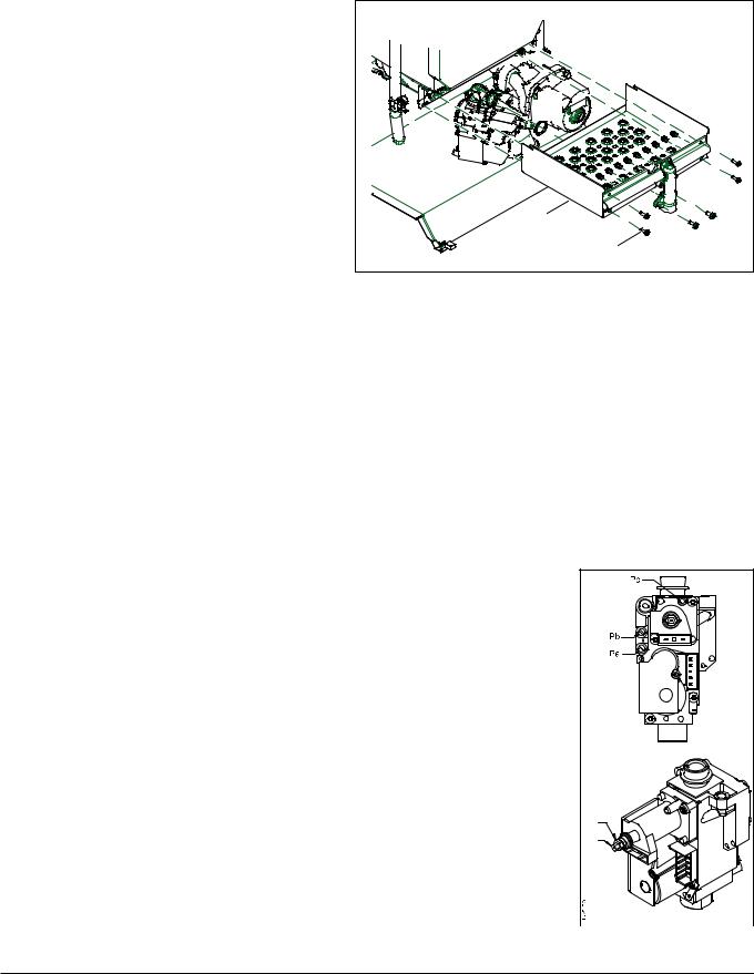
A) Replace the main burner injectors
•Disconnect the boiler from the power supply;
•remove the front panel of the boiler;
•remove the screws (a) connecting the injector ramp to the gas valve and burner;
•remove the injector ramp and the burner shield at the same time (b);
•replace the ramp injectors making sure to fully tighten
them to prevent gas leaks. Injector diameters are speciied in the burner injector-pressure table.
•correctly reposition the injector ramp and the burner shield (b);
•secure the screws connecting the injector ramp to
the burner and gas valve. Make sure the o-ring (c) between the gas valve and the injector ramp is correctly positioned;
•check the gas circuit for leaks.
c |
|
b |
|
a |
CG_2451 |
B) Parameterise the electronic board
•Power the boiler;
•set the (Fxx) parameters with the values indicated in the following table, depending on the gas type following the procedure described in the SETTING PARAMETERS section.
|
G20 |
|
G31 |
|
|
|
|
F02 |
0 |
|
1 |
|
|
|
|
F08 |
|
100 |
|
|
|
|
|
F09 |
|
100 |
|
|
|
|
|
F18 |
|
18 |
|
|
|
|
|
F45 |
|
1 |
|
|
|
|
|
F48 |
|
100 |
|
|
|
|
|
F64 |
|
1 |
|
|
|
|
|
C) Mechanically calibrate the gas valve pressure regulator
•Connect the positive pressure test point of a pressure gauge, possibly water-operated, to the gas valve pressure test point (Pb);
•open the gas tap and switch the boiler to the "Winter" mode;
•open a hot water tap that can provide a low rate of at least 10 litres a minute or make sure there is maximum heat demand;
C1) Adjust to nominal heat output:
•remove the modulator cover;
•adjust the tube brass screw (a) until the pressure values shown in the burner injector-pressure table correspond to the nominal heat output;
•make sure that the dynamic inlet pressure of the boiler, measured at the gas valve pressure test point (Pa) is correct, as indicated in the TECHNICAL SPECIFICATIONS section.
C2) Adjust to reduced heat output:
•disconnect the modulator power cable and adjust the screw (b) until the pressure values corresponding to the reduced power indicated in the burnerjectorin -pressure chart are obtained;
•reconnect the wire;
•mount the modulator cover and seal.
(A) |
(B) |
7110102.03 (1-06/13) |
34 |

Burner injector-pressure table
|
|
1.24 F - 24 F |
|
18 F - 14 F - 1.14 F |
||
|
|
|
|
|
|
|
Gas type |
G20 |
|
G31 |
G20 |
|
G31 |
|
|
|
|
|
|
|
Injector diameter (mm) |
1.35 |
|
0.85 |
1.18 |
|
0.77 |
|
|
|
|
|
|
|
Burner pressure (mbar*) |
2.1 |
|
5.4 |
3.6 |
|
7.8 |
REDUCED HEAT OUTPUT |
|
|
||||
|
|
|
|
|
|
|
Burner pressure (mbar*) |
11.8 |
|
28.8 |
11.6 |
|
24.7 |
RATED HEAT OUTPUT |
|
|
||||
|
|
|
|
|
|
|
N° injectors |
|
11 |
|
11 |
||
|
|
|
|
|
|
|
*1 mbar = 10.197 mm H2O
D)Electronically calibrate the gas valve
D1) Electronically adjust to reduced heat output:
• set parameter F08-F09 = 0 following the procedure described in the SETTING PARAMETERS section;
•open a hot water tap that can provide a low rate of at least 10 litres a minute or make sure there is maximum heat demand;
•slowly increase (not more than 2 points at a time) the value of parameter F45 until the pressure read with the pressure gauge increases; then reduce the value of F45 by 2 points and press  to save.
D2) Electronically adjust to nominal heat output:
•set parameters F08-F09 = 100, F48 = 50;
•open a hot water tap that can provide a low rate of at least 10 litres a minute or make sure there is maximum heat demand;
•slowly increase (not more than 2 points at a time) the value of parameter F48 until the pressure read with the pressure gauge reaches the value indicated in the burner pressure/injectors table (NOMINAL HEAT OUTPUT); then increase the value of F48 by 2 points;
•set parameters F64 = 0, F18 = 0 and press  to save;
•turn off the two-pole switch to disconnect the boiler from the power supply for at least 5 seconds;
•put the front panel back in place.
E) Final checks
• Note down the conversion on the boiler rating plate, specifying the type of gas and indicating that calibration was performed.
After performing electronic calibration, set parameter F08-F09 as shown in the table below.
|
24 F |
|
1.24 F – 18 F |
14 F |
|
1.14 F |
|
|||||
|
|
|
|
|
|
|
|
|
|
|
|
|
|
G20 - G25.1 |
|
G31 |
G20 - G25.1 |
|
G31 |
G20 - G25.1 |
|
G31 |
G20 - G25.1 |
|
G31 |
|
|
|
|
|
|
|
|
|
|
|
|
|
F08 |
055 |
|
060 |
100 |
|
050 |
|
060 |
050 |
|
060 |
|
|
|
|
|
|
|
|
|
|
|
|
|
|
F09 |
100 |
|
100 |
|
100 |
|
050 |
|
060 |
|||
|
|
|
|
|
|
|
|
|
|
|
|
|
If lashes on the display when calibrating the gas valve, disconnect the boiler from the power supply and repeat the calibration procedure starting from point B).
12.2 REPLACING THE GAS VALVE
When replacing the gas valve, perform the following operations:
•switch off the boiler;
•close the gas inlet valve;
•replace the gas valve;
•open the gas inlet valve and make sure there are no gas leaks;
•perform the operations described in points B, C, D of the GAS CONVERSION section.
12.3 GAS VALVE CALIBRATION
To calibrate the gas valve, perform the operations described in points B, C, D of the GAS CONVERSION section.
(en) n Sectio R INSTALLE
35 |
7110102.03 (1-06/13) |
INSTALLE R Sectio n (en)
12.4 REPLACING THE ELECTRONIC BOARD
When replacing the electronic valve, perform the following operations:
•disconnect the boiler from the mains power supply.
•remove the front panel of the boiler;
•replace the electronic board;
•power the boiler;
•set parameters F03 and F12 as described in the SETTING PARAMETERS section according to the boiler model indicated on the rating plate.
Electronically calibrate the gas valve as follows:
•connect the positive pressure test point of a pressure gauge, possibly water-operated, to the gas valve pressure test point (Pb);
•open the gas tap and switch the boiler to the Winter mode;
•open a hot water tap that can provide a low rate of at least 10 litres a minute or make sure there is maximum heat demand;
•press buttons  and together for 10 seconds. Press when "ON" appears on the display;
• press |
when "INF" appears on the display. The modulator current percentage lashes on the display; |
•press when the pressure gauge measures an increase from 0.2 to 0.4 mbar with respect to the value indicated in the burner pressure/injectors table (REDUCED POWER); the modulator current percentage appears on the display;
•press  when the pressure measured by the pressure gauge reaches the value indicated in the burner pressure/injectors table (NOMINAL HEATING OUTPUT);
•after calibration, "MEM" lashes on the display for 5 seconds.
If a pressure gauge is unavailable, the automatic gas valve calibration procedure can be performed as follows:
•open the gas tap and switch the boiler to the Winter mode;
•keep the front panel of the boiler closed;
•open a hot water tap that can provide a low rate of at least 10 litres a minute or make sure there is maximum heat demand;
•press buttons 

 and
and  together for 10 seconds. Press
  when "ON" appears on the display;
•after calibration, "MEM" lashes on the display for 5 seconds.
If one of the following symbols: C01 – C02 – C03 – C04 – C05 appears after calibration, repeat the gas valve calibration procedure.
Check the mechanical calibration of the gas valve pressure adjuster, as described in the GAS CONVERSION section, before electronically calibrating the gas valve
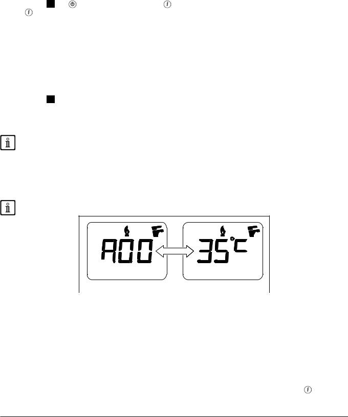
13.VISUALISATION OF PARAMETERS ON THE DISPLAY ("INFO" FUNCTION)
Press  for at least 6 seconds to display information concerning boiler operation.
When the “INFO” function is enabled, the message “A00” alternating with the boiler delivery temperature, is shown on the display:
CG_1808 |
Press buttons 
 to display the following information:
A00: current heating delivery temperature (°C);
A01: current DHW temperature (°C);
A02: current external temperature (°C) (with external sensor connected);
A03: current fumes temperature (°C);
A04: instantaneous (%) value of the gas valve control signal;
A05: power range (%) (MAX CH);
A06: heating setpoint temperature (°C);
A07: DHW temperature setpoint (°C);
A08: last error that occurred in the boiler;
A09: not used;
A10: not used.
This function remains active for 3 minutes. It is possible to interrupt the “INFO” function in advance by pressing |
or turning off |
the power to the boiler. |
|
7110102.03 (1-06/13) |
36 |

14.PARAMETER SETTINGS
To set the boiler parameters, press  and
and 

 together and hold down for at least 6 seconds. When the function is activated, the display shows “F01” alternated with the value of the parameter.
Edit parameters
•To scroll the parameters press 
 ;
;
•Press 


 buttons to change the single parameter value;
•Press  to save changes, the display shows “MEM”;
•Press  to leave the function without saving, the display shows "ESC".
ALL MODIFIED PARAMETERS SHOULD BE NOTED DOWN IN THE TABLE AT THE END OF THIS MANUAL.
Parameter |
Description of parameters |
|
Factory settings |
|
||||
|
|
|
|
|
|
|||
14 F |
1.14 F |
18 F |
24 F |
1.24 F |
||||
|
|
|||||||
|
|
|
|
|
|
|
|
|
F01 |
Boiler type 010=airtight chamber |
|
|
010 |
|
|
|
|
F02 |
Gas used 000=NATURAL GAS - 001=LPG - 002=gas G25.1 |
|
|
000 - 001 |
|
|
|
|
|
Hydraulic system |
|
|
|
|
|
|
|
F03 |
000 = instantaneous appliance |
000 |
004 |
000 |
|
000 |
004 |
|
003 = appliance with external storage boiler |
|
|||||||
|
|
|
|
|
|
|
||
|
004 = heating only appliance |
|
|
|
|
|
|
|
F04 - F05 |
Setting programmable relays 1 and 2 (See SERVICE instructions) |
|
|
000 |
|
|
|
|
000=no associated function |
|
|
|
|
|
|||
|
|
|
|
|
|
|
||
|
Maximum heating setpoint setting (°C) |
|
|
|
|
|
|
|
F06 |
000=85°C (Burner goes out at 90 °C) |
|
|
000 |
|
|
|
|
|
001=45°C (Burner goes out at 50 °C) |
|
|
|
|
|
|
|
F07 |
DHW inlet priority coniguration |
|
|
000 |
|
|
|
|
F08 |
CH max. output (0-100%) |
50 |
50 |
100 |
|
55 |
100 |
|
(60 LPG) |
(60 LPG) |
|
(60 LPG) |
|||||
|
|
|
|
|
||||
|
|
|
|
|
|
|
|
|
F09 |
DHW max. output (0-100%) |
100 |
50 |
100 |
|
100 |
100 |
|
(60 LPG) |
|
|||||||
|
|
|
|
|
|
|
||
|
|
|
|
|
|
|
|
|
F10 |
CH and DHW min. heat output (0-100%) |
|
|
000 |
|
|
|
|
F11 |
Delay prior to new ignition in CH mode |
|
|
003 |
|
|
|
|
000=10 seconds - 001...010 = 1...10 minutes |
|
|
|
|
|
|||
|
|
|
|
|
|
|
||
F12 |
Identiication of boiler model |
009 |
009 |
008 |
|
007 |
007 |
|
F13 |
Pump overrun time in heating mode |
|
|
003 |
|
|
|
|
000=10 seconds - 001...240 = 1...240 minutes |
|
|
|
|
|
|||
|
|
|
|
|
|
|
||
F14 |
Test of correct DHW probe position 000=Disabled - 001=Always |
|
|
000 |
|
|
|
|
enabled |
|
|
|
|
|
|||
|
|
|
|
|
|
|
||
F15 |
Factory setting |
|
|
000 |
|
|
|
|
F16 |
Anti-legionellosis function |
|
|
000 |
|
|
|
|
000 = Disabled - 055…067 = Enabled (setpoint 55…67°C) |
|
|
|
|
|
|||
|
|
|
|
|
|
|
||
F17 |
Hydraulic pressure switch coniguration |
|
|
001 |
|
|
|
|
F18 |
Release parameters for SERVICE |
|
|
000 |
|
|
|
|
|
|
Factory settings |
|
Parameter |
Description of parameters |
|
|
14 F - 1.14 F - 18 F |
|||
|
|
||
|
|
24 F - 1.24 F |
|
|
|
|
|
F19 |
Factory setting |
001 |
|
F20 |
Factory setting |
000 |
|
|
|
|
|
F21 |
Factory setting |
030 |
|
|
|
|
|
F22 |
Factory setting |
110 |
|
F23 |
Factory setting |
010 |
|
F24 |
Factory setting |
005 |
|
|
|
|
|
F25 |
Factory setting |
000 |
|
|
|
|
|
F26 |
Factory setting |
165 |
|
F27 |
Factory setting |
010 |
|
|
|
|
|
F28 |
Factory setting |
070 |
|
|
|
|
|
F29 |
Factory setting |
020 |
|
F30 |
Factory setting |
000 |
|
F31 |
Factory setting |
180 |
|
|
|
|
|
F32 |
Factory setting |
170 |
|
F33 - F34 |
Factory setting |
004 |
|
F35 |
Factory setting |
015 |
|
|
|
|
|
F36 |
Factory setting |
020 |
|
|
|
|
Parameter |
Description of |
Factory settings |
|
|
|||
|
|||
|
parameters |
14 F - 1.14 F - 18 F |
|
|
|
24 F - 1.24 F |
|
|
|
|
|
F44 |
Factory setting |
000 |
|
F45 |
Factory setting |
(this value depends on |
|
valve calibration) |
|||
|
|
||
|
|
|
|
F46 |
Factory setting |
015 |
|
F47 |
Factory setting |
000 |
|
F48 |
Factory setting |
(this value depends on |
|
valve calibration) |
|||
|
|
||
|
|
|
|
F49 |
Factory setting |
105 |
|
F50 |
Factory setting |
100 |
|
|
|
|
|
F51 |
Factory setting |
005 |
|
|
|
|
|
F52 |
Factory setting |
020 |
|
F53 |
Factory setting |
100 |
|
F54 |
Factory setting |
000 |
|
|
|
|
|
F55 |
Factory setting |
003 |
|
F56 |
Factory setting |
025 |
|
F57 |
Factory setting |
000 |
|
|
|
|
|
F58 |
Factory setting |
000 |
|
|
|
|
(en) n Sectio R INSTALLE
37 |
7110102.03 (1-06/13) |
INSTALLE R Sectio n (en)
F37 |
Factory setting |
003 |
F38 |
Factory setting |
000 |
F39 |
Factory setting |
067 |
|
|
|
F40 |
Factory setting |
070 |
|
|
|
F41 |
Factory setting |
010 |
F42 |
Factory setting |
042 |
|
|
|
F43 |
Factory setting |
001 |
|
|
|
F59 |
Factory setting |
005 |
F60 |
Factory setting |
120 |
F61 |
Factory setting |
015 |
|
|
|
F62 |
Factory setting |
030 |
|
|
|
F63 |
Factory setting |
025 |
F64 |
Factory setting |
000 |
|
|
|
15.TROUBLESHOOTING SERVICE FAULTS
The faults shown on the display are identiied with the symbol "E" and a number (fault code). For a complete list of faults, see the following table.
If "R" appears on the display the fault must be RESET by the user.
To reset, press and hold down for at least 2 seconds. If this fault persists, call the Authorised Service
Centre.
CODE |
FAULT |
POSSIBLE REASON |
SERVICE ACTION |
|
DISPLAYED |
||||
|
• No inlet gas pressure. |
• Check that the gas valve is open and there is no air in |
||
E01 |
Shut down for ignition |
|||
|
failure. |
• Ignition switch-lame sensor wire |
the gas supply circuit. |
|
|
|
interrupted. |
• Check the gas supply pressure. |
|
|
|
• Flame sensing electrode faulty or |
• Check the wire is uninterrupted and makes good |
|
|
|
incorrectly positioned. |
contact with the lame sensing electrode and the |
|
|
|
• Gas valve faulty. |
ignition switch. |
|
|
|
• Electronic board faulty. |
• Check the connections between the gas valve and the |
|
|
|
|
electronic board. |
|
|
|
|
• Check the lame sensing electrode is in good |
|
|
|
|
condition and in the right position (see the |
|
|
|
|
POSITIONING THE IGNITION AND FLAME- |
|
|
|
|
SENSING ELECTRODE section). |
|
E02 |
Shut down by safety |
• No water in the primary circuit |
• Check pump operation (unscrew the front cap and |
|
|
thermostat. |
(pump blocked or exchanger |
release the pump impeller with a screwdriver). |
|
|
|
obstructed). |
• Check the pump power input wiring. |
|
|
|
• Limit thermostat faulty. |
• Check that the limit thermostat is undamaged and |
|
|
|
• Limit thermostat wiring |
replace it if necessary. |
|
|
|
interrupted. |
• Check the continuity of the limit thermostat wiring. |
|
|
|
• CH low NTC probe faulty. |
• Check the CH low NTC probe (*). |
|
|
|
• Electronic board faulty. |
• Check whether the exchanger is clogged. |
|
E03 |
Board coniguration error. |
• Parameter F43 has not been set |
• Set parameter F43 with the value indicated in the |
|
|
|
correctly. |
table in the SETTING PARAMETERS section. |
|
E04 |
Safety error due to |
• See the reasons indicated in E01. |
• See the actions indicated in E01. |
|
|
ignition failure or frequent |
• See the reasons indicated in E42. |
• See the actions indicated in E42. |
|
|
lame loss. |
• CH low NTC probe faulty (circuit |
• Check the CH low NTC probe (*). |
|
E05 |
Flow sensor failure. |
|||
|
|
open or shorted). |
• Check the continuity of the CH low probe wiring. |
|
|
|
• CH low probe wiring interrupted |
• Make sure the wiring has not shorted. |
|
|
|
or shorted. |
|
|
E06 |
DHW sensor fault. |
• DHW low NTC probe faulty |
• Check the DHW NTC probe (*). |
|
|
|
(circuit open or shorted). |
• Check the continuity of the DHW probe wiring |
|
|
|
• DHW low probe wiring |
• Make sure the wiring has not shorted. |
|
|
|
interrupted or shorted. |
|
|
E07 |
Fumes NTC probe fault. |
• Fumes NTC probe faulty (circuit |
• Check the fumes NTC probe (**). |
|
|
|
open). |
• Check the continuity of the fumes probe wiring |
|
|
|
• Fumes probe wiring interrupted. |
• Check the continuity of the earth connections between |
|
E08 |
Error in the lame |
• The electronic board is not |
||
|
ampliication circuit. |
earthed. |
the electronic board (X4 connector) and the power |
|
|
|
• Electronic board faulty. |
supply terminal block. |
|
E09 |
Error in the gas valve |
• Electronic board faulty. |
• Replace the electronic board. |
|
|
safety circuit. |
• CH circuit pressure < 0.5 bar |
• If the pressure in the CH circuit is < 0.5 bar, perform |
|
E10 |
No hydraulic pressure |
|||
|
switch enable. |
• Hydraulic pressure switch faulty. |
illing (see the FILLING THE SYSTEM section). |
|
|
|
• Hydraulic pressure switch wiring |
• Check the hydraulic pressure switch works correctly. |
|
|
|
faulty. |
• Check the continuity of the hydraulic pressure switch |
|
|
|
|
wiring |
|
E22 |
Switching off due to power |
• Supply voltage V < 162V |
• Check whether the power supply reductions are due |
|
|
supply reductions. |
(automatic reset at V> 168V) |
to reasons other than the boiler. If so, contact the |
|
|
|
• Electronic board faulty. |
electricity provider. |
7110102.03 (1-06/13) |
38 |

CODE |
FAULT |
POSSIBLE REASON |
SERVICE ACTION |
|
DISPLAYED |
||||
|
• No water in the CH circuit |
• Check pump operation (unscrew the front cap and |
||
E25 |
No water safety trip. |
|||
|
|
(pump blocked or exchanger |
release the rotor with a screwdriver). |
|
|
|
obstructed). |
• Check the pump power input wiring. |
|
|
|
• CH low NTC probe faulty. |
• Check the CH low NTC probe (*). |
|
|
|
• Electronic board faulty. |
• Check whether the exchanger is clogged. |
|
E26 |
CH delivery NTC probe |
• See the reasons indicated in E25. |
• See the actions indicated in E25. |
|
|
overheating safety trip. |
• The electronic board is not |
• Check the continuity of the earth connections between |
|
E35 |
Parasite lame (lame |
|||
|
error). |
earthed. |
the electronic board (X4 connector) and the power |
|
|
|
• Flame sensing electrode faulty or |
supply terminal block. |
|
|
|
incorrectly positioned. |
• Check the lame sensing electrode is in good |
|
|
|
• Electronic board faulty. |
condition and correctly positioned (see the |
|
|
|
|
POSITIONING THE IGNITION AND FLAME- |
|
|
|
|
SENSING ELECTRODE section). |
|
E36 |
Fumes NTC probe fault. |
• Fumes NTC probe faulty |
• Check the fumes NTC probe (**). |
|
|
|
(shorted). |
• Make sure the fumes probe wiring has not shorted. |
|
|
|
• Fumes probe wiring shorted. |
|
|
E40 - E41 |
Shutdown due to probable |
• No inlet gas pressure. |
• Check the gas supply pressure (for natural gas |
|
|
obstruction of air-lue duct |
• Gas valve modulator wires not |
Palim.>9mbar). |
|
|
or insuficient gas inlet |
connected. |
• Check the connection of the gas valve modulator |
|
|
pressure. |
• Flame sensing electrode faulty or |
wiring to the electronic board. |
|
|
|
incorrectly positioned. |
• Check that the pressure at the burner has been |
|
|
|
• Fumes NTC probe faulty or |
correctly calibrated (see the GAS VALVE section). |
|
|
|
incorrectly positioned |
• Check the lame sensing electrode is in good |
|
|
|
• Air-lue duct obstructed. |
condition and correctly positioned (see the |
|
|
|
• Gas valve faulty. |
POSITIONING THE IGNITION AND FLAME- |
|
|
|
• Electronic board faulty. |
SENSING ELECTRODE section). |
|
|
|
|
• Check the fumes NTC probe (**). |
|
|
|
|
• Make sure the air and lue ducts are not obstructed |
|
|
|
|
and have been correctly installed (they must not |
|
|
|
|
exceed the prescribed maximum lengths and must |
|
|
|
|
be itted with the correct diaphragm – see the |
|
|
|
|
INSTALLING THE DUCTS section). |
|
E42 |
No lame. |
• Fan not working (fault or no |
• Check that the fan power supply wiring is connected |
|
|
|
power). |
to the electronic board. |
|
|
|
• Air-lue duct completely |
• Make sure the air and lue ducts are not obstructed |
|
|
|
obstructed. |
and have been correctly installed (they must not |
|
|
|
• Electronic board faulty. |
exceed the prescribed maximum lengths and must |
|
|
|
|
be itted with the correct diaphragm – see the |
|
|
|
|
INSTALLING THE DUCTS section). |
|
E43 |
Shutdown due to probable |
• See the causes indicated in E40 |
• See the actions indicated in E40 - E41. |
|
|
obstruction of air-lue duct |
- E41 |
• Check whether the power supply reductions are due |
|
|
or insuficient gas inlet |
• Input voltage V<180V |
to reasons other than the boiler. If so, contact the |
|
|
pressure. |
(automatically resets at V>185V |
electricity provider |
|
|
|
or by pressing “R”). |
|
|
|
|
• Electronic board faulty. |
|
|
E50 |
Shutdown due to fumes |
• Fumes temperature>180°C. |
• Check the heat exchange of the water/ fumes |
|
|
NTC probe tripping for |
• Insuficient heat exchange on the |
exchanger: insuficient circulation or presence of |
|
|
overheating. |
water/fumes exchanger. |
scale. |
|
|
|
• Fumes NTC probe faulty. |
• Check the fumes NTC probe (**). |
|
|
|
• Electronic board faulty. |
|
|
E55 |
Gas valve not |
• The electronic board has not |
• Electronically calibrate the gas valve (parameters F45 |
|
|
electronically calibrated |
been replaced and the gas valve |
and F48) as described in the GAS VALVE section |
|
|
|
has not yet been electronically |
|
|
|
|
calibrated. |
|
|
E62 |
Safety shutdown if the |
• Flame sensing electrode faulty or |
• Check the wire is uninterrupted and makes good |
|
|
lame signal or fumes |
incorrectly positioned. |
contact with the lame sensing electrode and the |
|
|
temperature fail to |
• Fumes NTC probe faulty. |
ignition switch. |
|
|
stabilise |
• Electronic board faulty. |
• Check the lame sensing electrode is in good |
|
|
|
|
condition and correctly positioned (see the |
|
|
|
|
POSITIONING THE IGNITION AND FLAME- |
|
|
|
|
SENSING ELECTRODE section). |
|
|
|
|
• Check the fumes NTC probe (**). |
|
E65 |
Safety shutdown if the air- |
• See the causes indicated in E40 |
• See the actions indicated in E40 - E41. |
|
|
lue duct obstruction test |
- E41. |
|
|
|
fails frequently. |
|
|
(en) n Sectio R INSTALLE
39 |
7110102.03 (1-06/13) |

INSTALLE R Sectio n (en)
CODE |
FAULT |
POSSIBLE REASON |
SERVICE ACTION |
|
DISPLAYED |
||||
|
• The electronic board has been |
• Set parameters F03 and F12 with the values indicated |
||
E98 |
Electronic board |
|||
|
parameters incorrectly |
replaced and not yet calibrated |
in the table in the SETTING PARAMETERS section |
|
|
conigured |
for the boiler model. |
according to the boiler model indicated on the rating |
|
|
|
• Parameters F03 and F12 have |
plate. |
|
|
|
not been set or have been |
|
|
|
|
incorrectly set. |
|
|
|
Boiler operating at |
• No inlet gas pressure. |
• Check the gas supply pressure |
|
|
reduced power. |
• Gas valve modulator wires not |
• (for natural gas Palim.>9mbar). |
|
|
|
connected. |
• Check the connection of the gas valve modulator |
|
|
|
• Flame sensing electrode faulty or |
wiring to the electronic board. |
|
Flashing |
|
incorrectly positioned. |
• Check that the pressure at the burner has been |
|
|
|
• Air-lue duct partially obstructed. |
correctly calibrated (see the GAS VALVE section) |
|
|
|
• Gas valve faulty. |
• Check the lame sensing electrode is in good |
|
|
|
• Electronic board faulty. |
condition and correctly positioned (see the |
|
|
|
|
POSITIONING THE IGNITION AND FLAME- |
|
|
|
|
SENSING ELECTRODE section). |
|
|
|
|
• Make sure the air and lue ducts are not obstructed |
|
|
|
|
and have been correctly installed (they must not |
|
|
|
|
exceed the prescribed maximum lengths and must |
|
|
|
|
be itted with the correct diaphragm – see the |
|
|
|
|
INSTALLING THE DUCTS section). |
CH = central heating DHW = domestic hot water
(*) DHW NTC and CH delivery probe: cold resistance value: approximately 10 kΩ @ 25° C (resistance decreases as temperature rises). (**) NTC fumes probe: cold resistance value: approximately 49 kΩ @ 25° C (resistance decreases as temperature rises).
7110102.03 (1-06/13) |
40 |

16.ADJUSTMENT AND SAFETY DEVICES
The boiler has been designed in full compliance with European reference standards and in particular is equipped with the following:
• Limit thermostat
Thanks to a sensor placed on the CH low line, this thermostat interrupts the low of gas to the burner if the water in the primary circuit overheats. In these conditions, the boiler is blocked and only after the fault has been eliminated can it be ignited again by pressing  for at least 2 seconds.
It is forbidden to disable this safety device.
• Electronic fumes outlet control
The boiler is itted with an electronic function which controls the fumes outlet.
• Flame ionisation detector
The lame sensing electrode, located in the centre of the burner, guarantees safety of operation in case of gas failure or incomplete ignition of the burner.
In these conditions, the boiler is blocked after 3 ignition attempts.
Press  for at least 2 seconds to re-establish normal operating conditions.
• Hydraulic pressure switch
This device allows the main burner to be ignited only if system pressure is higher than 0.5 bar.
• Heating circuit pump post-circulation
The electronically-controlled pump post-circulation function lasts 3 minutes and is enabled, in the heating mode, if the ambient thermostat causes the burner to go out.
• Anti-freeze device
The electronic boiler management system includes a "frost protection" function for the heating and DHW systems which, when low temperature falls below 5°C, operates the burner until a low temperature of 30°C is reached. This function is enabled when the boiler is switched on, the gas supply is open and the system is correctly pressurised.
• Water not circulating in primary circuit (pump probably blocked)
If there is insuficient or no water circulating in the primary circuit, the boiler blocks and the error code E25 is shown on the display.
• Pump anti-block function
If no heat demand is received in the heating and/or DHW modes for 24 consecutive hours, the pump will automatically start and
operate for 10 seconds.
This function is operative when the boiler is powered.
• Hydraulic safety valve (heating circuit)
This device is set to 3 bar and is used for the heating circuit.
Connect the safety valve to a drain trap. Do not use it to drain the heating circuit.
17.PUMP CAPACITY/ HEAD
This is a high static head pump it for installation on any type of single or double-pipe heating systems. The automatic air valve incorporated in the pump allows quick venting of the heating system.
KEY TO PUMP CHARTS - “SECTION” E
Q |
RATE OF FLOW |
H |
HEAD |
(en) n Sectio R INSTALLE
41 |
7110102.03 (1-06/13) |
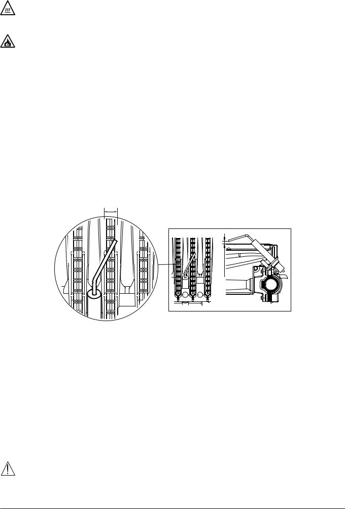
INSTALLE R Sectio n (en)
18.ANNUAL SERVICING
If the boiler was operating, wait for the combustion chamber and pipes to cool down.
Before commencing any maintenance operations, make sure the boiler is disconnected from the power supply. Afterwards, move the knobs and/or operating parameters of the boiler to their original positions.
Do not clean the boiler with abrasive, aggressive and/or easily lammable substances (such as petrol, acetone, etc.).
To optimise boiler eficiency, carry out the following annual controls:
•Check the appearance and airtightness of the gaskets of the gas and combustion circuits;
•Check the state and correct position of the ignition and lame-sensing electrodes;
•Check the state of the burner and make sure it is irmly ixed;
•Check for any impurities inside the combustion chamber. Use a vacuum cleaner to do this;
•Check the gas valve is correctly calibrated;
•Check the pressure of the heating system;
•Check the pressure of the expansion vessel;
•Check the fan works correctly;
•Make sure the lue and air ducts are unobstructed;
18.1 HYDRAULIC UNIT
For special areas, where the water is harder than 20 °F (1 °F = 10 mg calcium carbonate per litre of water), install a polyphosphate dispenser or an equivalent treatment system, compliant with current regulations.
18.2 POSITIONING THE ELECTRODE
L
CG_2399 |
mm |
3 ÷ 4 |
The electrode must completely cross the width (L) of the burner element.
18.3 CLEANING THE FILTERS
The DHW and CH ilters are housed inside removable cartridges (see igure in annex "SECTION" F at the end of this manual). The CH cartridge is located on the CH return line (F) while the DHW cartridge is on the cold water inlet (E). To clean the ilters, proceed as described below:
•switch off the boiler;
•shut the DHW inlet valve;
•drain the water in the CH circuit by opening valve (A);
•remove the clip (1-E/F) from the ilter as illustrated in the igure and take out the cartridge (2-E/F) containing the ilter, taking care not to apply excessive force;
•to extract the heating ilter cartridge, irst remove the 3-way valve motor (1-2G);
•eliminate any impurities and deposits from the ilter;
•reposition the ilter in the cartridge and put it back into its housing, securing it with the clip.
•The NTC DHW sensor is positioned in point (D).
when replacing and/or cleaning the O-rings on the hydraulic assembly, only use Molykote 111 as a lubricant, not oil or grease.
7110102.03 (1-06/13) |
42 |
18.4 REMOVING SCALE FROM THE D.H.W. CIRCUIT
The DHW circuit can be cleaned without removing the water-water exchanger from its housing if the plate was initially provided with the speciic tap (available on request) located on the DHW outlet (see igure in annex "SECTION" F at the end of this manual).
To clean, proceed as follows:
•Close the DHW inlet valve;
•Drain the DHW system by opening a hot water tap;
•Close the DHW outlet tap;
•Remove the clip (1E);
•Remove the ilter (2E);
•to replace the DHW NTC probe (D).
If the special tap is not supplied, dismount the water-water heat exchanger, as described in the next section, and clean it separately. Remove the scale from the seat and relative NTC sensor itted on the DHW circuit (D). To clean the exchanger and/or DHW circuit,
use Cillit FFW-AL or Benckiser HF-AL.
18.5 DISMOUNTING THE WATER-WATER HEAT EXCHANGER
The stainless steel plate-type water-water heat exchanger is easily disassembled with a screwdriver (see igure in annex "SECTION" F at the end of the manual ) by operating as described below:
•drain the system, just the boiler if possible, through the drain tap;
•drain the DHW system;
•remove the two screws at the front securing the water-water heat exchanger and pull it out (B).
Pay great attention when dismantling the individual parts of the hydraulic assembly. Do not use sharp tools, do not apply excessive force when removing the ixing clip.
19.COMBUSTION PARAMETERS
Tomeasurecombustioneficiencyandthetoxicityoftheproductsof combustion,theboilerisittedwithtwodedicatedtestpo ints. Oneconnectionpointisconnectedtotheexhaustductand isusedtomeasurecombustioneficiencyandthetoxicityofthe
products of combustion. The other is connected to the air intake circuit and is used to check for the presence of any products of combustion circulating in installations with co-axial lues.
The following parameters can be measured at the connection point on the lue gas circuit:
•temperature of the combustion products;
•concentration of oxygen (O2) or, alternatively, carbon dioxide (CO2);
•carbon monoxide (CO) concentration.
The temperature of the comburent air must be measured on the test point located on the air intake lue by inserting the measurement sensor by about 3 cm.
The combustions analisys shall be done using an analyzer regularly calibrated.
(en) n Sectio R INSTALLE
43 |
7110102.03 (1-06/13) |
 Loading...