


Neta-tec Combi GA
Installation & Servicing Instructions
Neta-tec Combi GA Range
Gas Fired Wall Mounted Condensing
Combination Boiler
These instructions include the Benchmark Commissioning Checklist
and should be left with the user for safe keeping.
They must be read in conjunction with the Flue Installation Guide.
© Baxi Heating UK Ltd 2014

Model Range
Baxi Neta-tec Combi 24 GA
o
47-075-51
G.C.N
Baxi Neta-tec Combi 28 GA
G.C.No 47-075-52
Baxi Neta-tec Combi 33 GA
G.C.No47-075-53
The Benchmark Scheme
Benchmark places responsibilities on both manufacturers and installers. The
purpose is to ensure that customers are provided with the correct equipment for
their needs, that it is installed, commissioned and serviced in accordance with the
manufacturer’s instructions by competent persons and that it meets the
requirements of the appropriate Building Regulations. The Benchmark Checklist
can be used to demonstrate compliance with Building Regulations and should be
provided to the customer for future reference.
Installers are required to carry out installation, commissioning and servicing work
in accordance with the Benchmark Code of Practice which is available from the
Heating and Hotwater Industry Council who manage and promote the Scheme.
Visit www.centralheating.co.uk for more information.
© Baxi Heating UK Ltd 2014 All rights reserved. No part of this publication may
be reproduced or transmitted in any form or by any means, or stored in any
retrieval system of any nature (including in any database), in each case whether
electronic, mechanical, recording or otherwise, without the prior written
permission of the copyright owner, except for permitted fair dealing under
Copyrights, Designs and Patents Act 1988.
Applications for the copyright owner’s permission to reproduce or make other
use of any part of this publication should be made, giving details of the proposed
use, to the following address:
Building Regulations and the Benchmark Commissioning
Checklist
Building Regulations (England & Wales) require notification of
the installation of a heating appliance to the relevant Local
Authority Building Control Department. This can be achieved
via a Competent Persons Self Certification Scheme as an
option to notifying the Local Authority directly.
The Health & Safety Executive operates the ‘Gas Safe Register’,
a self-certification scheme for gas heating appliances.
These arrangements represent a change from the situation
whereby compliance with Building Regulations was accepted as
being demonstrated by completion of the Benchmark Logbook
(which was then left on site with the customer).
With the introduction of Self Certification Schemes, the
Benchmark Logbook is being withdrawn. However, a similar
document in the form of a commissioning checklist and service
interval record is incorporated at the back of these instructions.
This company is a member of the Benchmark initiative and fully
supports the aims of the programme. Its aim is to improve the
standards of installation and commissioning of central heating
systems in the UK and to encourage the regular servicing of all
central heating systems to ensure safety and efficiency.
Building Regulations require that installations should comply
with manufacturer's instructions. It is therefore important that
the commissioning checklist is completed by the installer. The
relevant section of Building Regulations only relates to
dwellings. Therefore the checklist only applies if the appliance is
being installed in a dwelling or some related structure.
The Company Secretary, Baxi Heating UK Limited,
Brooks House, Coventry Road, Warwick. CV34 4LL
Full acknowledgement of author and source must be given.
WARNING: Any person who does any unauthorised act in relation to a
copyright work may be liable to criminal prosecution and civil claims for damages.
0086
The flowchart opposite gives guidance for installers on the
process necessary to ensure compliance with Building
Regulations.
2
© Baxi Heating UK Ltd 2014
ISO 9001
FM 00866
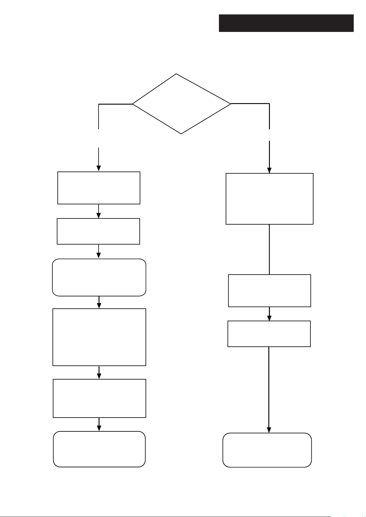
Choose Building
Regulations Notification
Route
Installer Notification Guidelines
Competent Person's
Self Certification Scheme
Install and Commission this
appliance to manufacturer's
instructions
Complete the
Benchmark Checklist
If you notify via the ‘Gas Safe
Register’, the register will issue
the Building Regulations
certificate on members’ behalf
Building Control
Contact your relevant Local
Authority Building Control
(LABC) who will arrange
an inspection or contact
a government approved
inspector
Install and Commission this
appliance to manufacturer's
instructions
Scheme Members only
Call ‘Gas Safe Register’ on:
0800 408 5577
or log onto:
www.gassaferegister.co.uk
within 10 days
You must ensure that the
certificate number issued by
the ‘Gas Safe Register’ is written
onto the Benchmark Checklist
‘Gas Safe Register’ will issue a
Building Regulations Compliance
Certificate to the property owner
and inform the relevant LABC
Complete the
Benchmark Checklist
LABC will record the data
and will issue a
certificate of compliance
© Baxi Heating UK Ltd 2014
3

Legislation
IMPORTANT - Installation, Commissioning, Service & Repair
This appliance must be installed in accordance with the manufacturer’s instructions and
the regulations in force. Read the instructions fully before installing or using the
appliance.
In GB, this must be carried out by a competent person as stated in the Gas Safety
(Installation & Use) Regulations.
Definition of competence: A person who works for a Gas Safe registered company
and holding current certificates in the relevant ACS modules, is deemed competent.
In IE, this must be carried out by a competent person as stated in I.S. 813 “Domestic
Gas Installations”.
The addition of anything that may interfere with the normal operation of the appliance
without express written permission from the manufacturer or his agent could invalidate
the appliance warranty. In GB this could also infringe the Gas Safety (Installation and
Use) Regulations.
Warning - Check the information on the data plate is compatible with local supply
conditions.
This company declare that no substances harmful to health
are contained in the appliance or used during appliance
manufacture.
The appliance is suitable only for installation in GB and IE and
should be installed in accordance with the rules in force, and
only used in a suitably ventilated location.
In GB, the installation must be carried out by a Gas Safe
Registered Installer. It must be carried out in accordance with
the relevant requirements of the:
• Gas Safety (Installation & Use) Regulations.
• The appropriate Building Regulations either The Building
Regulations, The Building Regulations (Scotland), Building
Regulations (Northern Ireland).
• The Water Fittings Regulations or Water Byelaws in
Scotland.
• The Current I.E.E. Wiring Regulations.
Where no specific instructions are given, reference should be
made to the relevant British Standard Code of Practice.
In IE, the installation must be carried out by a competent
Person and installed in accordance with the current edition of
I.S. 813 ‘Domestic Gas Installations’, the current Building
Regulations and reference should be made to the current ETCI
rules for electrical installation.
All Gas Safe registered engineers carry an ID card with their licence number and a
photograph. You can check your engineer is registered by telephoning
0800 408 5500 or online at www.gassaferegister.co.uk
The boiler meets the requirements of Statutory Instrument “ The Boiler (Efficiency)
o
Regulations 1993 N
3083” and is deemed to meet the requirements of Directive
92/42/EEC on the energy efficiency requirements for new hot water boilers fired with
liquid or gaseous fuels:-
Type test for purpose of Regulation 5 certified by:
Notified Body 0085.
Product/Production certified by:
Notified Body 0086.
For GB/IE only.
All systems must be thoroughly flushed and treated with
inhibitor (see section 6.2).
Codes of Practice - refer to the most recent version
In GB the following Codes of Practice apply:
Standard Scope
BS 6891 Gas Installation.
BS 5482 Part 1 Butane & Propane Gas Installation
BS 5546 Installation of hot water supplies for domestic
purposes.
BS EN 12828 Heating systems in buildings.
BS EN 12831 Heating systems in buildings - Calculation of load.
BS EN 14336 Installation & commissioning of water based
heating systems.
BS 6798 Installation of gas fired hot water boilers.
BS 5440 Part 1 Flues.
BS 5440 Part 2 Ventilation.
BS 7074 Expansion vessels and ancillary equipment for
sealed water systems.
BS 7593 Treatment of water in domestic hot water
central heating systems.
In IE the following Codes of Practice apply:
Standard Scope
I.S. 813 Domestic Gas Installations.
The following standards give valuable additional information;
BS 5546 Installation of hot water supplies for domestic
purposes.
BS EN 12828 Heating systems in buildings.
BS EN 12831 Heating systems in buildings - Calculation of load.
BS EN 14336 Installation & commissioning of water based
heating systems.
BS 7074 Expansion vessels and ancillary equipment for
sealed water systems.
BS 7593 Treatment of water in domestic hot water
central heating systems.
4
© Baxi Heating UK Ltd 2014

Safe Manual Handling
General
The following advice should be adhered to, from when first handling the boiler to the final stages of installation, and also during maintenance.
Most injuries as a result of inappropriate handling and lifting are to the back, but all other parts of the body are vulnerable, particularly shoulders, arms and hands.
Health & Safety is the responsibility of EVERYONE.
There is no ‘safe’ limit for one man - each person has different capabilities. The boiler should be handled and lifted by TWO PEOPLE.
Do not handle or lift unless you feel physically able.
Wear appropriate Personal Protection Equipment e.g. protective gloves, safety footwear etc.
Preparation
Co-ordinate movements - know where, and when, you are both going.
Minimise the number of times needed to move the boiler - plan ahead.
Always ensure when handling or lifting the route is clear and unobstructed. If possible avoid steps, wet or slippery surfaces, unlit areas etc. and take special care
on ladders/into lofts.
Technique
When handling or lifting always use safe techniques - keep your back straight, bend your knees. Don’t twist - move your feet, avoid bending forwards and
sideways and keep the load as close to your body as possible.
Where possible transport the boiler using a sack truck or other suitable trolley.
Always grip the boiler firmly, and before lifting feel where the weight is concentrated to establish the centre of gravity, repositioning yourself as necessary. See the
‘Installation’ section of these instructions for recommended lift points.
Remember
The circumstances of each installation are different. Always asses the risks associated with handling and lifting according to the individual conditions.
If at any time when installing the boiler you feel that you may have injured yourself STOP !!
DO NOT ‘work through’ the pain - you may cause further injury.
IF IN ANY DOUBT DO NOT HANDLE OR LIFT THE BOILER - OBTAIN ADVICE OR ASSISTANCE BEFORE PROCEEDING !!
© Baxi Heating UK Ltd 2014
5
CONTENTS
Section Page
1.0 Introduction 7
2.0 General Layout 8
3.0 Appliance Operation 9
4.0 Technical Data 10
5.0 Dimensions and Fixings 11
6.0 System Details 12
7.0 Site Requirements 15
8.0 Flue Options 20
9.0 Installation 22
10.0 Commissioning 27
11.0 Completion & System Draining 30
12.0 Servicing 31
13.0 Changing Components 33
14.0 Combustion & Calibration 42
15.0 Electrical 43
16.0 Short Parts List 44
17.0 Fault Finding & ‘Service Due’ 45
18.0 Optional Outdoor Sensor s 51
Benchmark Checklist 54
6
© Baxi Heating UK Ltd 2014

Information Label
1.0 Introduction
1.1 Description
1. The Baxi Neta-tec Combi GA Range are fully automatic gas
fired wall mounted condensing combination boilers. They are
room sealed and fan assisted, and will serve central heating and
mains fed domestic hot water.
2. The boiler is set to give a maximum output of :-
24 models - 24 kW DHW
21.2 kW CH (Condensing)
28 models - 28 kW DHW
25.3 kW CH (Condensing)
33 models - 33 kW DHW
29.6 kW CH (Condensing)
3. The boiler is factory set for use on Natural Gas (G20). It can
be adapted to operate on Propane (G31) - see Section 10.1
‘Gas Type Check’.
4. The boiler is suitable for use only on fully pumped sealed
heating systems. Priority is given to domestic hot water.
Fig. 1
Control Flap
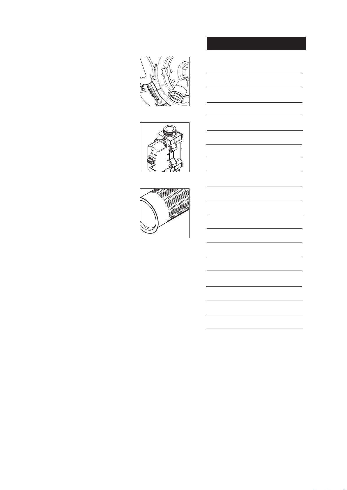
5. The boiler data badge gives details of the model, serial
number and Gas Council number and is situated on the control
box. It is visible when the case front panel is removed (Fig. 2).
6. The boiler model, serial number and Gas Council number are
also shown on the information label behind the boiler control
flap (Fig. 1). This is for user reference.
7. The boiler is intended to be installed in residential / domestic
environments on a governed meter supply only.
8. The boiler must be installed with one of the purpose
designed flues such as one of the standard horizontal telescopic
flue kits detailed in the Flue Installation Guide .
9. All systems must be thoroughly cleansed, flushed and
treated with inhibitor (see section 6.2).
1.2 Optional Extras
Various timers, external controls, etc. are available as optional
extras. Full details are contained in the relevant sales literature.
1.3 Contents of Pack
Gas Type Label
Fig. 2
© Baxi Heating UK Ltd 2014
The pack contains:-
• Boiler
• Wall Plate (including taps)
• Template
• Fittings & Literature Pack
Data Badge
NOTE: These Installation & Servicing Instructions MUST be
read in conjunction with the Flue Installation Guide supplied
in the Literature Pack.
7
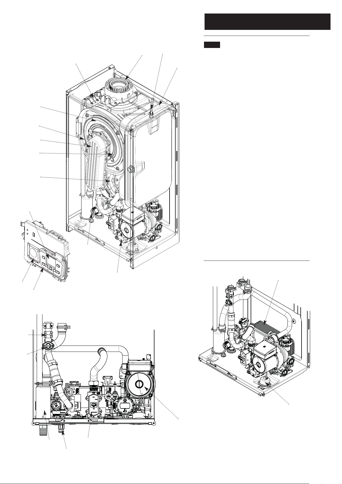
2.0 General Layout
2.1 Layout
2
3
12
11
10
9
7
13
15
8
1
1. Expansion Vessel
2. Boiler Adaptor
3. Primary Heat Exchanger
4. DHW Plate Heat Exchanger
5. Pump with Automatic Air Vent
6. Central Heating System Pressure Gauge
7. Fan Assembly
8. Exp. Vessel Locating Stud
9. Flame Sensing Electrode
10. Air/Gas Collector
11. Spark Ignition Electrode
12. Combustion Box Cover & Burner
13. Control Box Display
14. Condensate Trap
15. Safety Pressure Relief Valve
16. Gas Valve
17. Diverter Valve Motor
18. Boiler Control
19. Optional Timer
20. Boiler Drain Tap
21. Heating Flow Sensor
22. Safety Thermostat
17
19
18
21
22
5
14
20
16
4
6
8
© Baxi Heating UK Ltd 2014
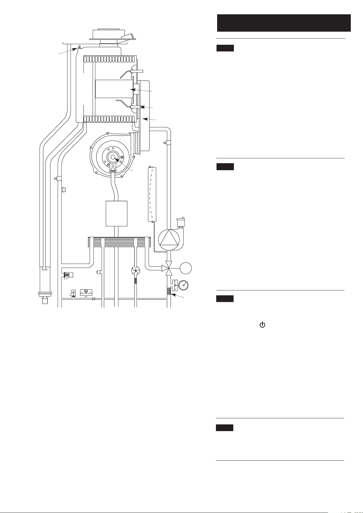
Boiler Schematic
Layout
19
3.0 Appliance Operation
18
26
17
16
14
8
12
10
20
21
22
23
24
25
28
27
15
13
1
2
3
7
6
M
4
3.1 Central Heating Mode
1. With a demand for heating, the pump circulates water
through the primary circuit.
2. Once the burner ignites the fan speed controls the gas
rate to maintain the heating temperature measured by the
temperature sensor.
3. When the flow temperature exceeds the setting
temperature, a 3 minute delay occurs before the burner
relights automatically (anti-cycling). The pump continues to
run during this period.
4. When the demand is satisfied the burner is extinguished
and the pump continues to run for a period of 3 minutes
(Pump Overrun).
3.2 Domestic Hot Water Mode
1. Priority is given to the domestic hot water supply. A
demand at a tap or shower will override any central heating
requirement.
2. The flow of water will operate the Domestic Hot Water
Sensor (‘Hall Effect Sensor’) which requests the 3 way valve
to change position. This will allow the pump to circulate the
primary water through the DHW plate heat exchanger.
3. The burner will light automatically and the temperature of
the domestic hot water is controlled by the temperature
sensor.
4. When the domestic hot water demand ceases the burner
will extinguish and the diverter valve will remain in the
domestic hot water mode, unless there is a demand for
central heating.
A
11
B
Key
1. Pump with Automatic Air Vent
2. Diverter Valve Assembly
3. Diverter Valve motor
4. CH System Pressure Gauge
5. Central Heating Filter
6. Domestic Hot Water Filter
7. Domestic Hot Water Priority Sensor
(‘Hall Effect Sensor’)
8. Domestic Hot Water NTC sensor
9. Non-return Valve
10. Hydraulic Pressure Sensor
11. Boiler Drain Tap
12. Pressure Relief Valve
13. Plate Heat Exchanger
9
D
C
14. Condensate Trap
15. Gas Valve
16. Safety Thermostat (105°C)
17. Heating Flow Sensor
18. Flue Sensor
19. Boiler Adaptor
20. Primary Heat Exchanger
21. Spark Ignition Electrode
22. Burner
23. Flame Sensing Electrode
24. Air/Gas Collector
25. Return Heating Sensor
26. Fan
27. Air/Gas Venturi
28. Expansion Vessel
Connections:A – Condensate Drain
B – Heating Flow
C – Domestic Hot Water Outlet
D – Gas Inlet
E – Cold Water Inlet On/Off Valve and filter
F – Heating Return
5
E
F
Fig. 3
3.3 Boiler Frost Protection Mode
1. The frost protection mode is integral to the appliance and
functions as long as there is power to the boiler, as indicated
by the standby signal .
2. With CH & DHW or CH only selected, when the boiler
temperature falls below 5°C the boiler will fire until a
temperature of 30°C is reached.
3. If DHW only is selected, when the boiler CH temperature
falls below 5°C the boiler will fire until a temperature of
30°C is reached. When the boiler DHW temperature falls
below 5°C the boiler will fire until a temperature of 7°C is
reached.
4. Further protection can be incorporated by using a system
frost thermostat.
3.4 Pump Protection
1. If the boiler has been inactive for a period of 24 hours the
pump will automatically operate for 1 minute to prevent
sticking.
© Baxi Heating UK Ltd 2014
9

4.0 Technical Data
4.1
Appliance Type C
Appliance Category CAT II
13 C33 C43 C53
2H 3P
Heat Input CH (Net) Max Min
24 model kW 20 3.5
28 model kW 24 3.9
33 model kW 28 4.8
Heat Output CH (Non-Condensing)
Max Min
24 model kW 20 3.4
28 model kW 24 3.8
33 model kW 28 4.7
Heat Output CH (Condensing)
Max Min
24 model kW 21.2 3.7
28 model kW 25.3 4.1
33 model kW 29.6 5.1
Heat Input DHW (Net) Max
24 model kW 24.7
28 model kW 28.9
33 model kW 34
Heat Output DHW Max
24 model kW 24
28 model kW 28
33 model kW 33
Injector
24 model mm 4.4
28 model mm 4.6
33 model mm 4.9
NATURAL GAS ONLY !
Max Gas Rate (Natural Gas - G20)
(After 10 mins)
3
24 model m
28 model m
33 model m
/h 2.54
3
/h 2.96
3
/h 3.49
Inlet Pressure (Natural Gas - G20)
mbar 20
PROPANE ONLY !
Max Gas Rate (Propane - G31)
(After 10 mins)
24 model kg/h 1.92
28 model kg/h 2.25
33 model kg/h 2.64
Inlet Pressure (Propane - G31)
mbar 37
Electrical Supply 230V~ 50H
(Appliance must be connected to an
earthed supply)
Power Consumption
24 model W 104
28 model W 116
33 model W 133
10
© Baxi Heating UK Ltd 2014
Electrical Protection
IPX5D
External Fuse Rating 3A
Internal Fuse Rating F2L
Condensate Drain
To accept 21.5mm (3/4in) plastic waste pipe
Flue Terminal Diameter 100mm
Dimensions Projection 125mm
Connections copper tails
Gas Inlet - 22mm
Heating Flow - 22mm
Heating Return - 22mm
Cold Water Inlet - 15mm
Hot Water Outlet - 15mm
Pressure Relief Discharge - 15mm
Outercase Dimensions
Casing Height - 700mm
Overall Height Inc Flue Elbow - 860mm
Casing Width - 390mm
Casing Depth - 300mm
Clearances
Above Casing 175mm Min
Below Casing 150mm Min*
Front 450mm Min (For Servicing)
Front 5mm Min (In Operation)
L.H. Side 5mm Min
R.H. Side 5mm Min :
*This is MINIMUM recommended dimension. Greater
clearance will aid installation and maintenance.
Weights
(24 model)
Packaged Boiler Carton 38.5kg
Installation Lift Weight 34 kg
(28 model)
Packaged Boiler Carton 38.5kg
Installation Lift Weight 34 kg
(33 model)
Packaged Boiler Carton 40.5kg
Installation Lift Weight 36kg
NOxClass 5
CO
2
N.G. 9.0% ± 0.7
L.P.G. 10.5% ± 1.0
Central Heating Primary Circuit
Pressures
bar
Safety Discharge 3
Max Operating 2.5
Min Operating 0.5
Recommended Operating Range 1-2
DHW Circuit bar
Pressures
Max Operating 8
Min Operating 0.15
Flow Rates (24) (28) (33)
l/min l/min l/min
DHW Flow Rate
@ 30o C Rise 10.9 12.9 15.3
DHW Flow Rate
@ 35o C Rise 9.8 11.5 13.5
Min Working
DHW Flow Rate 2 2 2
IMPORTANT: Where Low Flow Taps or Fittings are
intended to be used in the DHW system connected it is
strongly recommended that the DHW flow rate DOES
NOT fall below 2.5l/min. This will ensure reliable
operation of the DHW function.
Expansion Vessel - (For Central Heating only.
Integral with appliance)
bar
Min Pre-charge Pressure 0.5
(24 & 28) (33)
litre litre
Max Capacity of
CH System 100 100
Primary Water Content
of Boiler (unpressurised) 2.5 2.8
Temperatures
C.H. Flow Temp (adjustable)
25°C to 80°C max (± 5°C)
D.H.W. Flow Temp (adjustable)
SEDBUK Declaration
SAP 2005 Seasonal Efficiency for N. G.
models is 91.1%
SAP 2005 Seasonal Efficiency for L.P.G.
Pump
Available Head See graph below
models is 93.2%
SAP 2009 Annual Efficiency for N. G.
models is 89%
SAP 2009 Annual Efficiency for L.P.G.
models is 91%
z
This value is used in the UK Government’s Standard
Assessment Procedure (SAP) for energy rating of
dwellings. The test data from which it has been calculated
has been certified by 0087.
NOTE: All data in this section are nominal values
and subject to normal production tolerances.
6
5.5
5
4.5
4
3.5
3
2.5
2
Metre (wg)
1.5
1
0.5
0
0
35°C to 60°C max (± 5°C)
dependent upon flow rate
Pump - Available Head
200 400 600 800 1000 1200
Flow Rate (l/h)
 Loading...