


MULTI-BEAM

MULTI-BEAM
®
Sensors
Compact modular self-contained photoelectric sensing controls
Printed in USA P/N 32887
Product
Line
Specifications
•
•
•
•
•
Modular design with interchangeable components (scanner
blocks, power blocks, and logic timing modules);
over 5,000 sensor configurations possible
Scanner blocks for opposed, retro, diffuse, convergent, and
fiber optic sensing modes (including high-gain models)
Power blocks for ac or dc operation, including 2-wire ac
operation
Logic modules to support a wide variety of delay, pulse, limit,
and rate sensing logic functions
Most scanner blocks include Banner's exclusive, patented
AID™ (Alignment Indicating Device) system, which lights a
top-mounted indicator LED whenever the sensor sees its
own modulated light source, and pulses the LED at a rate
proportional to the strength of the received light signal.
3.7"
(94 mm)
1.6"
(40 mm)
4.5"
(114 mm)
2.1" (53 mm)
Status Indicator LED
(except emitters)
Lens Centerline
Access to
Sensitivity Adjustment
2.36"
(60.0 mm)
0.30"
(7.6 mm)
0.20"
(5.1 mm)
5 mm (#10) Screw
Clearance (4)
1.18"
(30.0 mm)
1/2" – 14 NPSM
Conduit Entrance
Banner Engineering Corp. 9714 Tenth Ave. No. Minneapolis, MN 55441 Telephone: (612)544-3164 FAX (applications): (612)544-3573
WARNING MULTI-BEAM
®
photoelectric presence sensors described in this catalog do NOT include the self-
checking redundant circuitry necessary to allow their use in personnel safety applications. A sensor failure or malfunction
can result in either an energized or a de-energized sensor output condition.
Never use these products as sensing devices for personnel protection. Their use as a safety device may create an unsafe
condition which could lead to serious injury or death.
Only MACHINE-GUARD and PERIMETER-GUARD Systems, and other systems so designated, are designed to meet OSHA and ANSI
machine safety standards for point-of-operation guarding devices. No other Banner sensors or controls are designed to meet these standards,
and they must NOT be used as sensing devices for personnel protection.
!
WARRANTY: Banner Engineering Corporation warrants its products to be free from defects for one year. Banner Engineering Corporation will
repair or replace, free of charge, any product of its manufacture found to be defective at the time it is returned to the factory during the warranty period.
This warranty does not cover damage or liability for the improper application of Banner products. This warranty is in lieu of any other warranty either
expressed or implied.
Contents
Introduction to MULTI-BEAM
®
Modular Sensors ........................... page 3
Selection of components and summary of available models ............ pages 4-6
MULTI-BEAM
®
3- and 4-wire Sensors............................................ pages 6-23
3- and 4-wire Scanner Blocks................................................. pages 6-14
3- and 4-wire Scanner Block modifications ........................... page 14
3- and 4-wire Power Blocks ................................................... pages 15-20
3- and 4-wire Logic Modules ................................................. pages 21-23
MULTI-BEAM
®
2-wire Sensors....................................................... pages 24-29
2-wire Scanner Blocks............................................................ pages 24-26
2-wire Power Blocks .............................................................. pages 27-28
2-wire Logic Modules ............................................................ page 29
MULTI-BEAM
®
Accessories............................................................ pages 30-31
Upper Covers (lens assemblies).............................................. page 30
Lower Covers ......................................................................... page 30
Mounting Brackets ................................................................. page 31
Quick Disconnect ................................................................... page 31
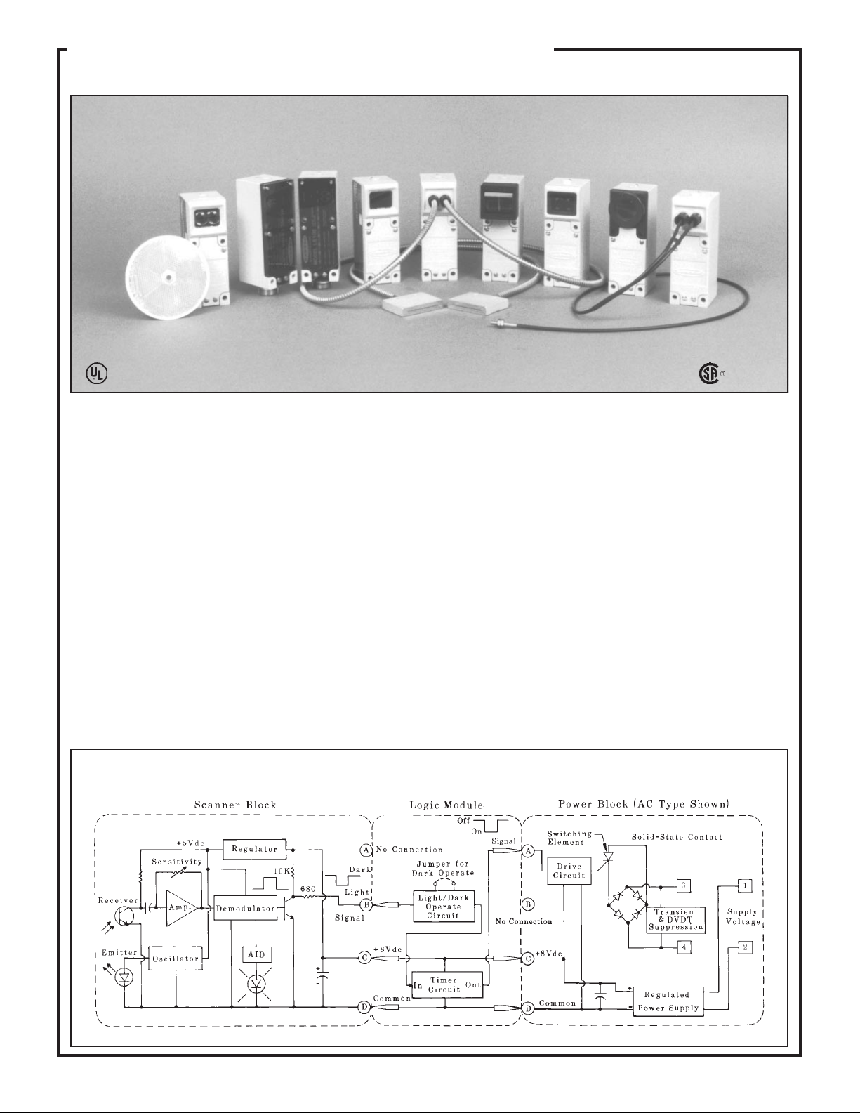
Banner MULTI-BEAM
®
sensors are compact modular self con-
tained photoelectric switches. Each MULTI-BEAM consists of
three components: scanner block, power block, and logic module.
The scanner block contains the complete modulated photoelectric
amplifier as well as the emitter and receiver optoelements. It also
contains the sensing optics and the housing for the other two
modules. The power block provides the interface between the
scanner block and the external circuit. It contains a power supply
for the MULTI-BEAM plus a switching device to interface the
circuit to be controlled. The logic module interconnects the power
block and scanner block both electrically and mechanically. It
provides the desired timing logic function (if any), plus the ability
to program the output for either light- or dark-operate. The
emitters of MULTI-BEAM emitter-receiver pairs do not require
a logic module. Emitter scanner blocks are supplied with a blade-
pin to interconnect the scanner block and power block. This
modular design, with field-replaceable power block and logic
module, permits over 5,000 sensor configurations, resulting in
exactly the right sensor for any photoelectric application.
There are two families of MULTI-BEAM sensors: 3- and 4-wire,
and 2-wire. Three- and four-wire MULTI-BEAMs offer the
greatest selection of sensor configurations. They permit either ac
or dc operation and offer the fastest response times and the
greatest sensing ranges. Two-wire MULTI-BEAMs are used in
ac-powered applications where simplicity and convenience of
wiring are important. They are physically and electrically inter-
changeable with heavy-duty limit switches.
The circuitry of all MULTI-BEAM components is encapsulated
within rugged, corrosion-resistant VALOX
®
housings, which
meet or exceed NEMA 1, 3, 12, and 13 ratings. Most MULTI-
BEAM scanner blocks include Banner's patented Alignment
Indicating Device (AID™) which lights a top-mounted LED
when the sensor sees its own modulated light source and pulses
the LED at a rate proportional to the received light signal. Most
MULTI-BEAM sensor assemblies are UL listed and certified by
CSA (see power block listings). All MULTI-BEAM components
(except power block models 2PBR and 2PBR2) are totally solid-
state for unlimited life.
Composite Functional Schematic, 3- and 4-wire Sensors
®
3
MULTI-BEAM
Sensors
LR41887
E71083
MULTI-BEAM sensors are made up of three components: scanner
block, power block, and logic module. This is true for all MULTI-
BEAMs with the exception of opposed mode emitter units which
require only a power block (no logic module).
The first decision in the component selection process is to determine
which family of MULTI-BEAM sensors is appropriate for the applica-
tion: 3- and 4-wire, or 2-wire.
Next, decide which scanner block (within the selected family) is best for
the application. The guidelines in the catalog introduction will help you
to determine the best sensing mode. Then narrow the choice by
comparing the specifications listed in the following charts and on the
pages referenced in the charts.
Finally, choose a power block and logic module to complete the
MULTI-BEAM assembly. Components snap together without inter-
wiring to form a complete photoelectric sensing system that meets your
exact requirements while maintaining the simplicity of a self-contained
sensor.
If you have any questions about selecting MULTI-BEAM components,
please contact your Banner sales engineer or call Banner's Applications
Department at (612) 544-3164 during normal business hours.
Scanner Blocks Model Sensing Mode Range Response Page
SBE & SBR1 Opposed: high speed 150 feet 1 millisecond p. 7
SBED & SBRD1 Opposed: high speed, narrow beam 10 feet 1 millisecond p. 7
SBEX & SBRX1 Opposed: high power, long range 700 feet 10 milliseconds p. 7
SBEV & SBRX1 Opposed: visible beam 100 feet 10 milliseconds p. 7
SBEXD & SBRXD1 Opposed: high power, wide beam angle 30 feet 10 milliseconds p. 7
SBLV1 Retroreflective: high speed, visible beam 30 feet 1 millisecond p. 8
SBLVAG1 Retroreflective: polarized beam (anti-glare) 15 feet 1 millisecond p. 8
SBL1 Retroreflective: high speed, infrared beam 30 feet 1 millisecond p. 8
SBLX1 Retroreflective: high power, long range 100 feet 10 milliseconds p. 8
SBD1 Diffuse (proximity): high speed 12 inches 1 millisecond p. 9
SBDL1 Diffuse (proximity): medium range 24 inches 1 millisecond p. 9
SBDX1 Diffuse (proximity): high power, long range 6 feet 10 milliseconds p. 9
SBDX1MD Diffuse (proximity): wide beam angle 24 inches 10 milliseconds p. 9
SBCV1 Convergent beam: high speed, visible red 1.5-inch focus 1 millisecond p. 10
SBCVG1 Convergent beam: high speed, visible green 1.5-inch focus 1 millisecond p. 10
SBC1 Convergent beam: high speed, infrared 1.5-inch focus 1 millisecond p. 10
SBC1-4 Convergent beam: high speed, infrared 4-inch focus 1 millisecond p. 10
SBC1-6 Convergent beam: high speed, infrared 6-inch focus 1 millisecond p. 10
SBCX1 Convergent beam: high power, infrared 1.5-inch focus 10 milliseconds p. 10
SBCX1-4 Convergent beam: high power, infrared 4-inch focus 10 milliseconds p. 10
SBCX1-6 Convergent beam: high power, infrared 6-inch focus 10 milliseconds p. 10
SBEF & SBRF1 Opposed fiber optic (glass fibers): high speed see specs 1 millisecond p. 11
SBEXF & SBRXF1 Opposed fiber optic (glass fibers): high power see specs 10 milliseconds p. 11
SBFX1 Fiber optic (glass fibers): high power, infrared see specs 10 milliseconds p. 11
SBF1 Fiber optic (glass fibers): high speed, infrared see specs 1 millisecond p. 12
SBF1MHS Fiber optic (glass fibers): very high speed see specs 0.3 millisecond p. 12
SBFV1 Fiber optic (glass fibers): visible red see specs 1 millisecond p. 13
SBFVG1 Fiber optic (glass fibers): visible green see specs 1 millisecond p. 13
SBAR1 Ambient light receiver see specs 10 milliseconds p. 14
SBAR1GH Ambient light receiver: high gain see specs 10 milliseconds p. 14
SBAR1GHF Ambient light receiver: for glass fiber optics see specs 10 milliseconds p. 14
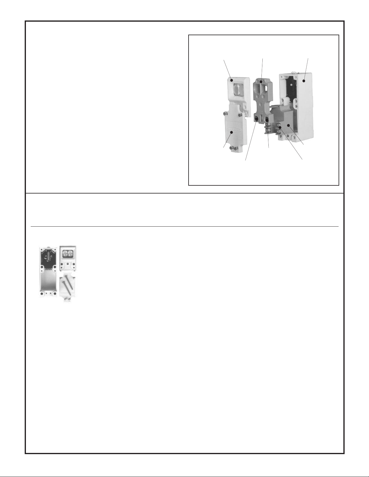
3- and 4-wire Systems (pages 6 through 23)
Upper Cover (lens)
(supplied with
Scanner Block)
Lower Cover
(supplied with
Scanner Block)
Logic
Timing
Adjustment
LIGHT/DARK
Operate Select
Power
Block
Wiring
Terminals
Scanner Block
Housing
Logic Module
4
Selection of MULTI-BEAM Components
Logic Modules Model Timing Logic Function Time Range(s) Page
LM1 ON/OFF (no timing function), light operate only NOTE for items below: other p. 21
LM3 ON/OFF (no timing function), light or dark operate time ranges available (p. 23) p. 21
LM5 ON-delay .15 to 15 seconds p. 22
LM5R OFF-delay .15 to 15 seconds p. 22
LM5-14 ON & OFF delay .15 to 15 seconds (both delays) p. 22
LM5T Limit timer (time-limited ON/OFF) .15 to 15 seconds p. 22
LM4-2 One-shot, retriggerable .01 to 1 second p. 21
LM4-2NR One-shot, non-retriggerable .01 to 1 second p. 22
LM8-1 Delayed one-shot .15 to 15 seconds (both times) p. 23
LM8A ON-delay one-shot .15 to 15 seconds (both times) p. 23
LM6-1 Rate sensor 60 to 1200 pulses per minute p. 22
LM8 Repeat cycle timer .15 to 15 seconds (both times) p. 23
LM2 Alternate action, divide by 2 p. 21
LM10 Alternate action, divide by 10 p. 23
LMT Test module p. 23
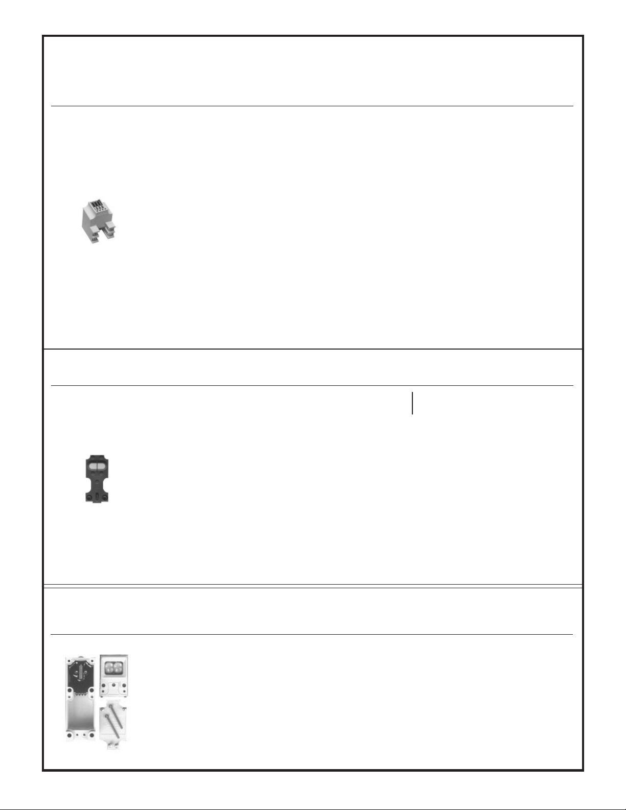
3- and 4-wire Systems (pages 6 through 23)
2-wire Systems (pages 24 through 29)
Agency
Power Blocks Model Input Voltage Output Configuration Approvals Page
PBT 10 to 30V dc SPST NPN (sink), 250mA maximum UL & CSA p. 15
PBT2 10 to 30V dc SPDT NPN (sink), 250mA each output p. 15
PBP 10 to 30V dc SPST PNP (source), 250mA maximum UL & CSA p. 15
PBT-1 10 to 30V dc No output: for powering emitters UL & CSA p. 16
PBT48 44 to 52V dc SPST NPN (sink), 250mA maximum p. 15
PBP48 44 to 52V dc SPST PNP (source), 250mA maximum p. 15
PBT48-1 44 to 52V dc No output: for powering emitters p. 16
PBD-2 11 to 13V ac (50/60Hz) SPST SCR, 3/4 amp maximum p. 17
PBD 22 to 28V ac (50/60Hz) SPST SCR, 3/4 amp maximum UL & CSA p. 17
PBD-1 22 to 28V ac (50/60Hz) No output: for powering emitters p. 19
PBA 105 to 130V ac (50/60Hz) SPST SCR, 3/4 amp maximum UL & CSA p. 17
PBAQ 105 to 130V ac (50/60Hz) SPST SCR, normally closed, 3/4 amp max. UL & CSA p. 19
PBAT 105 to 130V ac (50/60Hz) SPST isolated transistor, 100mA max. (ac or dc) UL & CSA p. 18
PBO 105 to 130V ac (50/60Hz) SPST isolated transistor, 50mA max. (dc only) UL & CSA p. 18
PBAM 105 to 130V ac (50/60Hz) Voltage source: 8V dc at 8ma max. UL & CSA p. 18
PBA-1 105 to 130V ac (50/60Hz) No output: for powering emitters UL & CSA p. 19
PBB 210 to 250V ac (50/60Hz) SPST SCR, 3/4 amp maximum UL & CSA p. 17
PBBT 210 to 250V ac (50/60Hz) SPST isolated transistor, 100mA max. (ac or dc) UL & CSA p. 18
PBOB 210 to 250V ac (50/60Hz) SPST isolated transistor, 50mA max. (dc only) UL & CSA p. 18
PBB-1 210 to 250V ac (50/60Hz) No output: for powering emitters UL & CSA p. 19
Scanner Blocks Model Sensing Mode Range Response Page
SBE & 2SBR Opposed 150 feet 10 milliseconds p. 25
2SBL1 Retroreflective 30 feet 10 milliseconds p. 25
2SBD1 Diffuse (proximity): short range 12 inches 10 milliseconds p. 26
2SBDX1 Diffuse (proximity): long range 30 inches 10 milliseconds p. 26
2SBC1 Convergent beam 1.5-inch focus 10 milliseconds p. 25
2SBC1-4 Convergent beam 4-inch focus 10 milliseconds p. 25
2SBF1 Fiberoptic see specs 10 milliseconds p. 26
5
Power Blocks Model Input Voltage Output Configuration Agency Approvals Page
2PBD 22 to 28V ac (50/60Hz) 2-wire, SPST SCR, 3/4 amp max. UL & CSA p. 27
2PBA 105 to 130V ac (50/60 Hz) 2-wire, SPST SCR, 3/4 amp max. UL & CSA p. 27
2PBB 210 to 250V ac (50/60Hz) 2-wire, SPST SCR, 3/4 amp max. UL & CSA p. 27
2PBR 105 to 130V ac (50/60Hz) 4-wire, SPST E/M relay, 5 amps max. p. 27
2PBR2 105 to 130V ac (50/60Hz) 4-wire, SPDT E/M relay, 5 amps max. p. 27
2-wire Systems (pages 24 through 29)
Logic Modules Model Timing Logic Function Time Range(s) Page
2LM3 ON/OFF (no timing) p. 29
2LM5 ON-delay .15 to 15 seconds p. 29
2LM5R OFF-delay .15 to 15 seconds p. 29
2LM5-14 ON & OFF delay .15 to 15 seconds (both delays) p. 29
2LM5T Limit timer (time limited ON/OFF) .15 to 15 seconds (both delays p. 29
2LM4-2 One-shot, retriggerable .01 to 1 second p. 29
LMT Test module p. 23
Other MULTI-BEAM Systems (described in Banner product catalog or in the data sheets noted below)
MULTI-BEAM 3- & 4-WIRE
SCANNER BLOCKS
Edgeguide Systems (data sheet 03506) Optical Data Transmitter (data sheet 03321) Light Screen System (data sheet 03557)
6
DESCRIPTION
MULTI-BEAM 3- & 4-wire scanner blocks offer a complete comple-
ment of sensing modes. There are 3 or more models for each sensing
mode, resulting in a choice of exactly the right sensor for any applica-
tion. The high power models (10 millisecond response time) offer
greater optical sensing power than any other industrial sensors.
SPECIFICATIONS
SUPPLY VOLTAGE: input power and output connections are made
via a 3- or 4-wire power block (see pages 15 to 20).
RESPONSE TIME: 1 millisecond ON and OFF, except high gain
models with "X" suffix and ambient light receivers which are 10
milliseconds ON and OFF.
REPEATABILITY OF RESPONSE: see individual sensor specs.
SENSITIVITY ADJUSTMENT: easily accessible, located on top of
scanner block beneath o-ring gasketed screw cover. 15-turn clutched
control (rotate clockwise to increase gain).
ALIGNMENT INDICATOR: red LED on top of scanner block.
Banner's exclusive, patented Alignment Indicating Device (AID™)
circuit lights the LED whenever the sensor detects its own modulated
light source, and pulses the LED at a rate proportional to the received
light level.
CONSTRUCTION: reinforced VALOX
®
housing with components
totally encapsulated. Stainless steel hardware. Meets NEMA standards
1, 3, 12, and 13.
OPERATING TEMPERATURE RANGE: -40 to +70 degrees C
(-40 to +158 degrees F).
VALOX
®
is a registered trademark of General Electric Company.
Functional Schematic, 3- and 4-wire Scanner Block
Dimensions, 3- and 4-wire Scanner Block
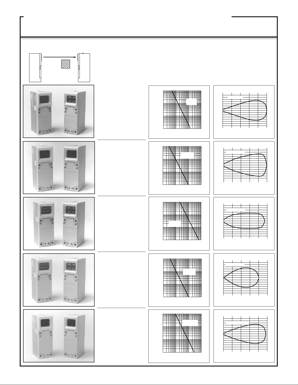
SBEX & SBRX1
Range: 700 feet (200m)
Response: 10ms on/off
Repeatability: 0.7ms
Beam: infrared, 940nm
Effective beam: 1" dia.
SBEV & SBRX1
Range: 100 feet (30m)
Response: 10ms on/off
Repeatability: 0.1ms
Beam: visible red, 650nm
Effective beam: 1" dia.
SBEXD &
SBRXD1
Range: 30 feet (9m)
Response: 10ms on/off
Repeatability: 0.7ms
Beam: infrared, 880nm
Effective beam: .14" dia.
SBED & SBRD1
Range: 10 feet (3m)
Response: 1ms on/off
Repeatability: 0.03ms
Beam: infrared, 880nm
Effective beam: .14" dia.
SBE & SBR1
Range: 150 feet (45m)
Response: 1ms on/off
Repeatability: 0.03ms
Beam: infrared, 940nm
Effective beam: 1" dia.
SBE/SBR1: this opposed pair has the highest gain available at 1 ms response.
SBED/SBRD1: fast response and small effective beam; will detect objects as small as .14 inch in crossection
moving at up to 10 feet per second. Best choice for repeatability of position sensing.
SBEX/SBRX1: best choice for opposed sensing in extremely dirty environments. Use for outdoor applications
and all applications requiring opposed range of 100 feet or more. Also useable side-by-side for long-distance
mechanical convergent sensing. Alignment difficult beyond 400 feet.
SBEV/SBRX1: SBEV has visible red beam for easiest alignment and system monitoring.
SBEXD/SBRXD1: wide beam angle and high gain for the most forgiving emitter-receiver alignment.
10
1
DISTANCE
100
1000
.1 FT 1 FT 10 FT 100 FT
SBED &
SBRD1
E
X
C
E
S
S
G
A
I
N
I
10
1
DISTANCE
100
1000
1 FT
SBEX &
SBRX1
10 FT 100 FT 1000 F
T
E
X
C
E
S
S
G
A
I
N
I
10
1
DISTANCE
100
1000
.1 FT 1 FT 10 FT 100 FT
SBEXD &
SBRXD1
E
X
C
E
S
S
G
A
I
N
I
10
1
DISTANCE
100
1000
1 FT
SBEV &
SBRX1
10 FT 100 FT 1000FT
E
X
C
E
S
S
G
A
I
N
I
20
0
I
N
C
H
E
S
OPPOSED DISTANCE--FEET
4 6 8 10
4
8
12
4
8
12
SBED/SBRD1
10
1
DISTANCE
100
1000
1 FT
SBE &
SBR1
10 FT 100 FT 1000FT
E
X
C
E
S
S
G
A
I
N
I
0
0
20
40
60
20
40
60
150 450 600 750
I
N
C
H
E
S
SBEX/SBRX1
OPPOSED DISTANCE--FEET
300
250
0
I
N
C
H
E
S
OPPOSED DISTANCE--FEET
50 75 100 150
5
10
15
5
10
15
SBEV/SBRX1
0
0
10
20
30
10
20
30
6 12 18 24 32
I
N
C
H
E
S
SBEXD/SBRXD1
OPPOSED DISTANCE--FEET
Models Excess Gain
Sensing Mode
MULTI-BEAM 3- & 4-wire Scanner Blocks
300
0
I
N
C
H
E
S
OPPOSED DISTANCE--FEET
60 90 120 150
20
40
60
20
40
60
SBE/SBR1
OBJECT
OPPOSED Mode
7
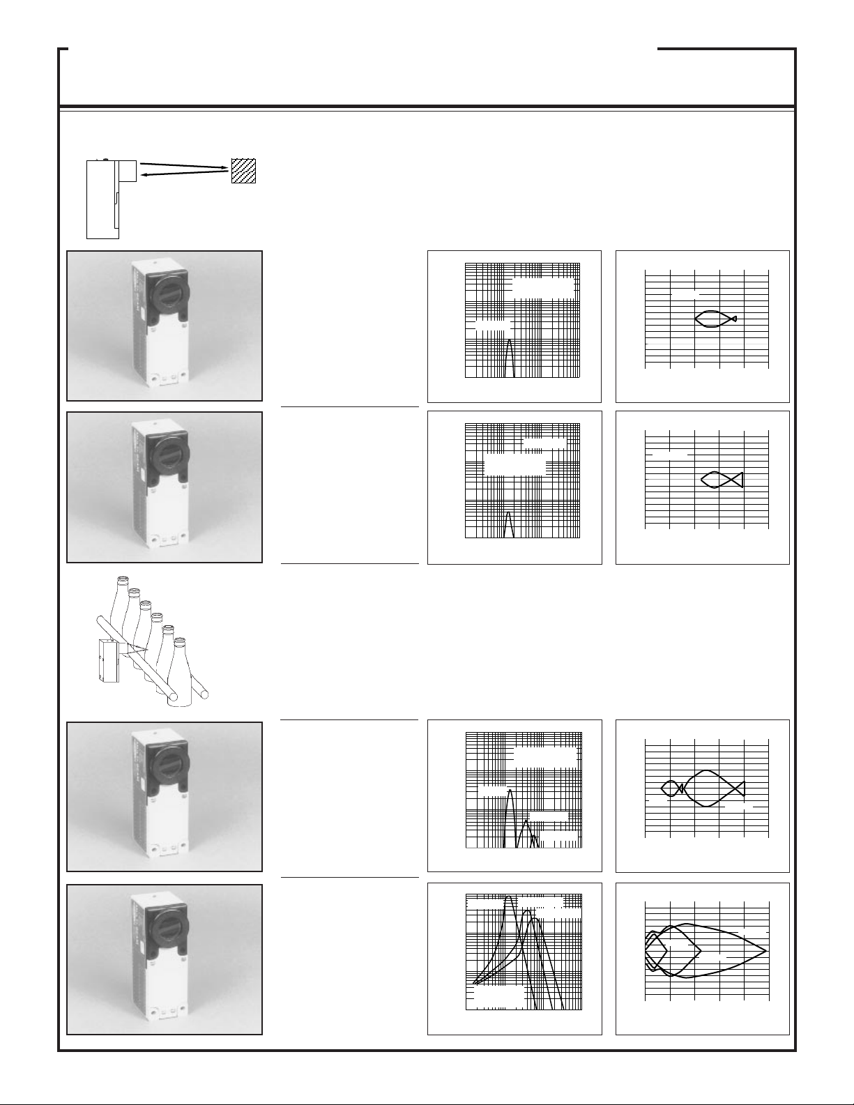
Beam Pattern
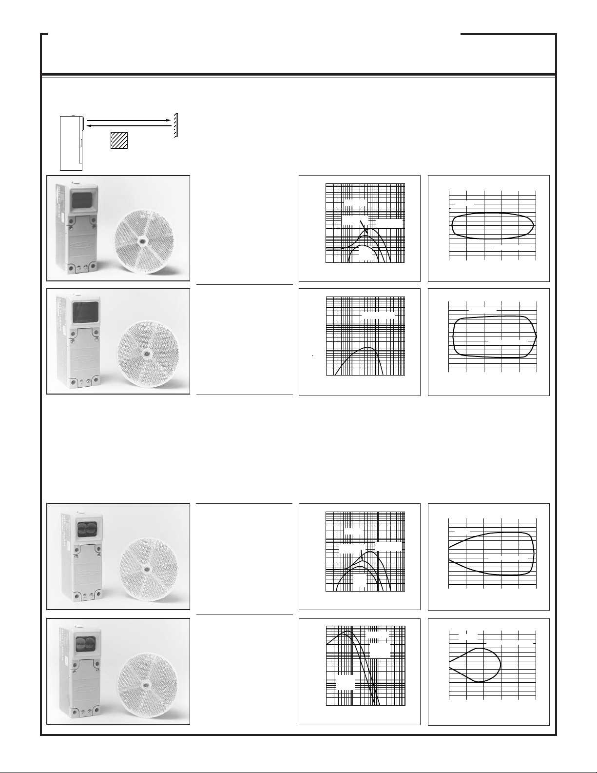
RETROREFLECTIVE
Mode
SBLV1: visible beam makes alignment very easy, and is the first choice for most retroreflective applications.
Not for use in dirty environments; rather use opposed mode or see SBL1 & SBLX1, below. Do not locate
retroreflector closer than 6 inches (15cm) from sensor.
SBLVAG1: uses anti-glare filter for immunity to direct reflections from shiny objects. Use only with models
BRT-3 or BRT-1.5 retroreflective targets. Use only in clean environments. Do not locate retroreflector closer
than 12 inches (30cm) from sensor.
SBL1: use where invisible beam is advantageous (e.g. security applications or film processing). First choice for
retroreflective sensing in slightly or moderately dirty environments. Do not use when the object to break the
beam has a shiny surface, unless the angle of light to the surface can be predicted.
SBLX1: highest gain available in a retroreflective sensor. Use for all applications requiring more than 30-foot
range where opposed mode sensors cannot be used. Objects must pass at a distance of at least 10 feet from the
sensor to be reliably sensed.
NOTE: for detailed information on
available retroreflective materials, see
the Banner product catalog.
SBLV1
Range: 6 in. to 30 ft.
(0,15 to 9m)
Response: 1ms on/off
Repeatability: 0.3ms
Beam: visible red, 650nm
SBLVAG1
Range: 12 in. to 15 ft.
(0,3 to 4.5m)
Response: 1ms on/off
Repeatability: 0.3ms
Beam: visible red, 650nm
SBL1
Range: 1 in. to 30 ft.
(2,5cm to 9m)
Response: 1ms on/off
Repeatability: 0.3ms
Beam: infrared, 940nm
SBLX1
Range: 10 to 75 ft. (3 to
22m) with one BRT-3 target;
10 to 100 ft. (3 to 30m) with
three BRT-3 targets
Response: 10ms on/off
Repeatability: 1.5ms
Beam: infrared, 880nm
MULTI-BEAM 3- & 4-wire Scanner Blocks
10
1
DISTANCE
100
1000
.1 FT 1 FT 10 FT 100 FT
with BRT-3 3"
reflector
with BRT-1 1"
reflector
with
BRT-T
tape
SBLV1
E
X
C
E
S
S
G
A
I
N
I
10
1
DISTANCE
100
1000
.1 FT 1 FT 10 FT 100 FT
E
X
C
E
S
S
G
A
I
N
I
SBLVAG1
10
1
DISTANCE
100
1000
.1 FT 1 FT 10 FT 100 FT
with BRT-3 3"
reflector
with BRT-1 1"
reflector
with
BRT-T
tape
SBL1
E
X
C
E
S
S
G
A
I
N
I
10
1
DISTANCE
100
1000
1 FT
with one
BRT-3 3"
reflector
SBLX1
with three
BRT-3 3"
reflectors
10 FT
100 FT 1000 FT
E
X
C
E
S
S
G
A
I
N
I
0
0
2
4
6
2
4
6
6 12 18 24 32
I
N
C
H
E
S
SBLV1
DISTANCE TO REFLECTOR--FEET
with BRT-3 reflector
0
0
1
2
3
1
2
3
3 6 9 12 15
I
N
C
H
E
S
SBLVAG1
DISTANCE TO REFLECTOR--FEET
with BRT-3 reflector
0
0
2
4
6
2
4
6
6 12 18 24 32
I
N
C
H
E
S
SBL1
DISTANCE TO REFLECTOR--FEET
with BRT-3 reflector
0
0
10
20
30
10
20
30
25 50 75 100 125
I
N
C
H
E
S
SBLX1
DISTANCE TO REFLECTOR--FEET
with one BRT-3 reflector
OBJECT
RETRO
TARGET
8
Models Excess Gain
Sensing Mode
Beam Pattern
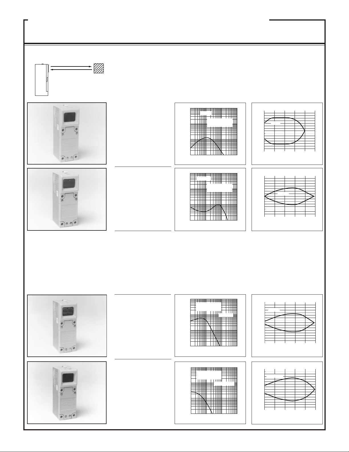
SBDX1
Range: 6 feet (2m)
Response: 10ms on/off
Repeatability: 1.5ms
Beam: infrared, 880nm
SBDX1MD
Range: 24 inches (60cm)
Response: 10ms on/off
Repeatability: 1.5ms
Beam: infrared, 880nm
APPLICATION NOTE: as a general rule
regarding background objects in diffuse sens-
ing, verify that the distance to the nearest
background object is at least three times the
distance from the sensor to the object to be
sensed. For example, if a product passes one
inch from an SBD1 sensor, the nearest back-
ground object should be at least three inches
further away.
SBDX1: first choice for diffuse (proximity) mode applications when there is no requirement for less than 10 ms
response and where there are no background objects to falsely return light. High excess gain for reliable detection
of most materials with low reflectivity which pass within 10 inches (25cm) of the sensor.
SBDX1MD: wide beam angle for forgiving alignment to reflective objects. First choice for detection of clear or
translucent glass or plastics. High excess gain at close range, with fast fall-off of gain near the maximum sensing
distance for optical suppression of reflective background. This model may be created from model SBDX1 by
substituting upper cover (lens) model UC-DMB.
SBD1
Range: 12 inches (30cm)
Response: 1ms on/off
Repeatability: 0.3ms
Beam: infrared, 940nm
SBDL1
Range: 24 inches (60cm)
Response: 1ms on/off
Repeatability: 0.3ms
Beam: infrared, 940nm
DIFFUSE Mode
10
1
DISTANCE
100
1000
.1 IN 1 IN 10 IN
100 IN
(Range based on 90
%
reflectance white
test card)
SBD1
E
X
C
E
S
S
G
A
I
N
I
10
1
DISTANCE
100
1000
.1 IN 1 IN 10 IN
100 IN
(Range based on 90
%
reflectance white
test card)
SBDL1
E
X
C
E
S
S
G
A
I
N
I
10
1
DISTANCE
100
1000
(Range based on 90
%
reflectance white
test card)
1 IN
SBDX1
10 IN 100 IN 1000 IN
E
X
C
E
S
S
G
A
I
N
I
10
1
DISTANCE
100
1000
(Range based on 90
%
reflectance white
test card)
SBDX1MD
1 IN 10 IN 100 IN
1000 IN
E
X
C
E
S
S
G
A
I
N
I
0
0
DISTANCE TO 90% WHITE TEST CARD--INCHES
.1
.2
.3
.1
.2
.3
3 6 9 12 15
I
N
C
H
E
S
SBD1
0
0
DISTANCE TO 90% WHITE TEST CARD--INCHE
S
.25
.5
.75
.25
.5
.75
5 10 15 20 25
I
N
C
H
E
S
SBDL1
0
0
DISTANCE TO 90% WHITE TEST CARD--INCHES
1
2
3
1
2
3
15 30 45 60 75
I
N
C
H
E
S
SBDX1
0
0
DISTANCE TO 90% WHITE TEST CARD--INCHE
S
.5
1
1.5
.5
1
1.5
5 10 15 20 25
I
N
C
H
E
S
SBDX1MD
MULTI-BEAM 3- & 4-wire Scanner Blocks
OBJECT
9
SBD1: short range diffuse mode sensor with relatively wide field of view. Loses gain rapidly near the end of its
range. As a result, its response to background objects is suppressed. However, use caution when applying any
diffuse mode sensor if background reflectivity exceeds the reflectivity of the object to be sensed.
SBDL1: longer range than SBD1, but with less response to objects passing the sensor at close range, and greater
sensitivity to background objects. Models SBD1 and SBDL1 are identical except for their upper cover (lens)
assembly (SBD1 uses UC-D; SBDL1 uses UC-L; see Upper Cover Chart in the Banner product catalog).
Models Excess Gain
Sensing Mode
Beam Pattern
SBCV1
Focus at: 1.5 inch (38mm)
Response: 1ms on/off
Repeatability: 0.3ms
Beam: visible red, 650nm
SBCVG1
Focus at: 1.5 in. (38mm)
Response: 1ms on/off
Repeatability: 0.3ms
Beam: visible green, 560nm
SBC1-4
Focus at: 4 inches (10cm)
SBCV1: .06-inch (1.5mm) dia. visible red spot, for precise positioning, edge-guiding, & small parts detection.
Sensor-to-product distance must be consistent. Some products ≥1" tall may be sensed against immediate
background like parts on a conveyor. Excellent for high-contrast registration-sensing applications (except red-on-
white). Use with LM6-1 logic module for speed detection sensing gear teeth, pulley hubs, or chain links.
SBCVG1: .12-inch (3mm) diameter visible green spot. Use to detect color differences (e.g. color registration
marks), including red-on-white combinations. For subtle shade variations, use model FO2BG (see Banner product
catalog).
SBC1, SBC1-4, SBC1-6: infrared LED light source provides higher gain for reliable sensing of products of low
reflectivity, while controlling sensing depth of field. Does not offer the same precision possible with visible light
models. Good for sensing clear materials within the sensor's depth of field. Good for reliably counting the flow
of radiused products which are kept at a fixed distance from the sensor (e.g. bottles against conveyor guide rail).
SBCX1, SBCX1-4, SBCX1-6: these models offer the greatest optical gain available in any reflective mode sensor.
They reliably detect most non-reflective black materials in applications where opposed mode sensing is not
possible (e.g. web break monitoring). Not meant for ignoring background objects (see excess gain charts).
SBC1
Focus at: 1.5 inch (38mm)
SBC1-6
Focus at: 6 inches (15cm)
Response: 1ms on/off
Repeatability: 0.3ms
Beam: infrared, 940nm
SBCX1
Focus at: 1.5 inch (38mm)
SBCX1-4
Focus at: 4 inches (10cm)
SBCX1-6
Focus at: 6 inch (15cm)
Response: 10ms on/off
Repeatability: 1.5ms
Beam: infrared, 880nm
10
1
DISTANCE
100
1000
.1 IN 1 IN 10 IN
100 IN
(Range based on 90
%
reflectance white
test card)
SBCV1
E
X
C
E
S
S
G
A
I
N
I
10
1
DISTANCE
100
1000
.1 IN 1 IN 10 IN
100 IN
SBCVG1
(Range based on 90
%
reflectance white
test card)
E
X
C
E
S
S
G
A
I
N
I
10
1
DISTANCE
100
1000
.1 IN 1 IN 10 IN
100 IN
(Range based on 90
%
reflectance white
test card)
SBC1
SBC1-4
SBC1-6
E
X
C
E
S
S
G
A
I
N
I
10
1
DISTANCE
100
1000
.1 IN 1 IN 10 IN
100 IN
(Range based on
90% reflectance
white test card)
SBCX1
SBCX1-4
SBCX1-6
E
X
C
E
S
S
G
A
I
N
I
0
0
DISTANCE TO 90% WHITE TEST CARD--INCHE
S
.04
.08
.12
.04
.08
.12
.5 1.0 1.5 2.0 2.5
I
N
C
H
E
S
SBCVG1
0
0
I
N
C
H
E
S
DISTANCE TO 90% WHITE TEST CARD--INCHES
.040
.080
.120
.040
.080
.120
1.5 3.0 4.5 6.0 7.5
SBC1-4
SBC1
0
0
DISTANCE TO 90% WHITE TEST CARD--INCHE
S
.08
.16
.24
.08
.16
.24
8 16 24 30 36
I
N
C
H
E
S
SBCX1
SBCX1-4
SBCX1-6
Counting radiused
products
Beam Pattern
0
0
I
N
C
H
E
S
DISTANCE TO 90% WHITE TEST CARD--INCHE
S
.040
.080
.120
.040
.080
.120
.50 1.0 2.0 2.5
SBCV1
1.5
MULTI-BEAM 3- & 4-wire Scanner Blocks
CONVERGENT Mode
OBJECT
Excess GainModels
Sensing Mode
10
 Loading...