


 Loading...
SureCross Web Configurator
rev. - 2/14/2012 134421
Contents |
|
Contents |
|
Web Configurator ...................................................................................................................................... |
3 |
Logging into the Web Configurator ...................................................................................................................................... |
3 |
Changing the Device's IP Address ............................................................................................................................. |
4 |
Selecting a Host Communication Protocol .................................................................................................................. |
5 |
Get ALL ....................................................................................................................................................................... |
5 |
Change, Refresh, Send, and Update Commands ...................................................................................................... |
6 |
RF Devices Tab ................................................................................................................................................................... |
6 |
Select Models ............................................................................................................................................................. |
6 |
Configure Points ......................................................................................................................................................... |
9 |
Expanded Configure Points ...................................................................................................................................... |
11 |
I/O Linking ................................................................................................................................................................. |
17 |
Scaling ...................................................................................................................................................................... |
18 |
Remote I/O ................................................................................................................................................................ |
19 |
Network Tab ...................................................................................................................................................................... |
25 |
Modbus Data Submenu ............................................................................................................................................ |
25 |
Modbus RTU Setup Submenu .................................................................................................................................. |
29 |
Modbus TCP Setup Submenu .................................................................................................................................. |
33 |
System Tab ........................................................................................................................................................................ |
38 |
Data Submenu .......................................................................................................................................................... |
38 |
Action Rules Submenu ............................................................................................................................................. |
41 |
Setup Submenu ........................................................................................................................................................ |
45 |
Advanced Tab .................................................................................................................................................................... |
50 |
Scheduler Submenu ................................................................................................................................................. |
50 |
Data Logger Submenu .............................................................................................................................................. |
54 |
E-mail Alerts Submenu ............................................................................................................................................. |
58 |
Script BASIC Submenu ............................................................................................................................................. |
62 |
Basic Configuration Examples ........................................................................................................................................... |
64 |
Setting up the Devices .............................................................................................................................................. |
65 |
Configuring I/O .......................................................................................................................................................... |
65 |
Linking I/O ................................................................................................................................................................. |
66 |
Link Timeouts ............................................................................................................................................................ |
67 |
System Network Settings .......................................................................................................................................... |
68 |
Advanced Configuration .................................................................................................................................................... |
69 |
Thresholds ................................................................................................................................................................ |
70 |
Data and Event Logging ........................................................................................................................................... |
70 |
Scheduling ................................................................................................................................................................ |
72 |
Trending Data ........................................................................................................................................................... |
73 |
Scaling ...................................................................................................................................................................... |
74 |
Troubleshooting ................................................................................................................................................................. |
75 |
Restoring Factory Default Settings ........................................................................................................................... |
75 |
Error Codes ............................................................................................................................................................... |
75 |
2 |
rev. - |

Web Configurator
The SureCross™ DX80 GatewayPro and DX83 Ethernet Bridge devices use an XML file to configure the network. To access the XML file, use any web browser and enter the device’s IP address into the browser’s address window:
http://192.168.0.1
The web configuration pages are arranged with a hierarchy of index tabs. The upper row of tabs is the top of the hierarchy and selects a broad topic. Top level tabs open related tabs on the next levels down. The middle tab selects a sub-topic, and the bottom tabs select individual pages within the sub-topic. The bottom of each page includes a Quick Help section listing usage tips or instructions specific to that page.
The XML file on any Ethernet Bridge or GatewayPro does not necessarily contain the settings for a specific wireless network. In many cases, the XML file saved in the Ethernet Bridge or GatewayPro is a default configuration file. Attaching the Ethernet Bridge or GatewayPro to the radio network does not automatically transfer network or device settings to the Ethernet Bridge or to the XML file.
When viewing real-time data returned to the browser by the connected device, the browser displays the data received when the page displayed. At this time, update data by clicking the Refresh button or the web browser’s Reload or Refresh button. Each time a page update is requested, new real-time data displays.
For more information on specific SureCross components, please refer to the data sheets for the SureCross devices:
•Gateways
•Line-Powered Nodes
•FlexPower™ Nodes
Logging into the Web Configurator
The SureCross™ Pro and DX83 Ethernet Bridge devices use an XML file to configure the network. To access the XML file, use any web browser set up for a direct connection to the Internet. If problems occur while connecting, verify the browser is not set to use a proxy server.
When connecting to the Ethernet Bridge, GatewayPro, or MultiHop Pro directly from a host computer, a crossover Ethernet cable is required; when connecting through a switch or Ethernet hub, use a standard Ethernet cable.
The factory default IP address for the devices is: 192.168.0.1.
To change the device’s default IP address, first set up the host PC with an IP address different from the Ethernet Bridge, GatewayPro, or MultiHop Pro IP addresses. (Please refer to Banner document 133116 for detailed instructions on setting up the host computer’s network IP address.) For example, change the PC host IP address to: 192.168.0.2.
After changing the host’s IP address, open a web browser and log into the Ethernet Bridge, GatewayPro, or MultiHop Pro by typing the IP address in the browser location window: http://192.168.0.1.
rev. - |
www.bannerengineering.com - tel: 763-544-3164 |
3 |

SureCross Web Configurator
After entering the IP address, the home web page for the SureCross device displays. To log in, click on any tab at the top of the page. To log out, close the browser.
For user-level access, enter the following as the user name and password.
•User name: system
•Password: admin
For Admin-level access, enter the following as the user name and password:
•User name: root
•Password: sxi
Admin-level access allows administrators to set up system users and their passwords. Admin-level access is also required to change the IP address of the system.
Changing the Device's IP Address
Once logged into the system, use the page tabs at the top of the page to select the path: System > Setup > Network. To change the Ethernet Bridge or GatewayPro’s IP address:
1.Type in the new IP address
2.Click the Change IP button.
3.Cycle power to the device. The IP address change activates when the device reboots.
4 |
www.bannerengineering.com - tel: 763-544-3164 |
rev. - |

SureCross Web Configurator
IMPORTANT! Verify the new IP address is correct before cycling power to the device. After the IP address changes, you must use the new IP address to access these configuration screens. Print this page and file for your records.
Selecting a Host Communication Protocol
By default the Ethernet Bridge and GatewayPro systems communicate with a host using Modbus/TCP. After establishing the IP address of the Ethernet Bridge and host, the system is set up to use Modbus/TCP.
The system can also use EtherNet/IP™. To change the system to EtherNet/IP, follow the previous instructions regarding the device and host IP address, and then:
1.Log in using the following user name and password. User name: root Password: sxi
2.At the bottom of the System > Setup > Network page is a checkbox to enable EtherNet/IP. Only select this box if the GatewayPro system is running on an EtherNet/IP network. This change cannot be enabled from a login other than the “root” login.
3.After selecting the EtherNet/IP Enabled checkbox, click the Set Ports button to save any changes made to the HTTP Port, Modbus Server Port, Telnet Port, or EtherNet/IP Enabled settings.
4.Cycle power to the Ethernet Bridge or GatewayPro to complete this update. After the device powers up, the changes should be registered.
Get ALL
For an existing network, perform a Get ALL for the devices and save the XML file before changing any network parameters. The default XML file stored on the Ethernet Bridge or GatewayPro may not accurately represent your configured network.
rev. - |
www.bannerengineering.com - tel: 763-544-3164 |
5 |
SureCross Web Configurator
The Get ALL command retrieves the parameters on the Configure Points and I/O Linking pages. These parameters are specific to the wireless network. The Get ALL command does not retrieve parameters involving the host system or the wired network components.
1.From the RF Devices > Select Models screen, verify the DX80 radio devices are defined using the Models drop-down list and the device name. If you make any changes to this list, select the Change box, then click the Update button to send the new device list to the GatewayPro.
2.Select the Get ALL checkbox for each radio device in the wireless network.
3.Click the Update button to retrieve configuration information from each DX80 device.
4.The Get ALL command will take a few minutes to complete. Click on the Check Status button to review the status of the command. When all devices are "Ready," the command has finished.
Saving Changes to the XML File
To permanently save the changes to the XML file, go to the System > Setup > Config File page and click the Save button. Changes made by clicking an Update button are temporary and only submitted to the Ethernet Bridge or GatewayPro, not the XML file.
Change, Refresh, Send, and Update Commands
Buttons commonly appearing on most configuration screens are the Change, Refresh, Send, and Update buttons. Each of these buttons performs a slightly different task.
Change If you leave any Web Configurator screen without clicking the Change button to submit the changes to the Ethernet Bridge or GatewayPro, all changes are lost.
Refresh Click the Refresh button to refresh the screen image. This updates any information on the screen that may have changed on the device.
Send Clicking the Send button transmits device and I/O parameters to the radio devices. The Send operation usually requires several second to complete.
Up- Clicking the Update button sends information to date the Ethernet Bridge or GatewayPro or retrieves in-
formation depending on which checkboxes are selected: Change or Get/Send All. Updating information does not save configuration information permanently to the XML file.
RF Devices Tab
Use the RF Devices tab to configure the radio network devices and I/O points.
Select Models
The Select Models tab displays the list of devices for the radio network. Use this screen to define the wireless network devices.
6 |
www.bannerengineering.com - tel: 763-544-3164 |
rev. - |

SureCross Web Configurator
Defining a Device
To define the DX80 radio network devices:
1.Select the device from the drop-down list, always using device zero for the Gateway. Most device descriptions can apply to either the Gateway or the Node.
2.Name the device.
3.Select the Change checkbox.
4.Click the Update button to send this information to the Ethernet Bridge.
Using the Change checkbox and Update buttons sends the only device name and model to the Ethernet Bridge/GatewayPro device. This will not overwrite existing I/O parameter information.
After the devices are defined and named, retrieve any existing parameter configuration information from the DX80 devices and load these settings into the GatewayPro or Ethernet Bridge:
1.Select the Get ALL checkbox for each device.
2.Click the Update button.
The Get ALL command will take a few minutes to complete. Click on the Check Status button to review the command's status.
Copying a Defined Device
When setting up a radio network that includes devices with the same configuration, set up one device and copy it using the Copy button at the bottom of the screen. Copying one device’s setup to another device also copies the Configure Points information. To copy device parameters, fill in the From and To boxes with the appropriate device number (listed on the left side of the table) and click the Copy button.
Submitting Parameters to the DX80 Devices
After defining the devices in the radio network, including the items from the Configure Points screen, the expanded Configure Points screen, and the I/O Linking screen, check the Send ALL box for the devices and click the Update button on the Select Models screen.
rev. - |
www.bannerengineering.com - tel: 763-544-3164 |
7 |
SureCross Web Configurator
This sends the I/O point configuration information to the DX80 devices. Once the Send ALL function has begun, click the Check Status button at the bottom of the screen. A monitoring screen displays each device’s progress.
Other Commands
Check Click the Check Status button to watch the sta- Status tus of a Get ALL or Send ALL command. Sending or retrieving information from the DX80 devi-
ces can take several minutes. Use the Check Status button to verify the error status of the data transfer. When the list reads "Ready," the command has finished.
Get Select the Get ALL checkbox and click the Up- ALL date button to pull set-up parameters from the
DX80 devices. These parameters will be loaded into the Web Configurator screens but will not be automatically saved into the XML file. Before modifying any existing radio network devices, always perform a Get ALL to update the Web Configurator with accurate set-up information.
Prev If there are more than 16 devices or rules/maps, and use the Prev and Next buttons to display the Next next screen of information.
Send After defining and setting up the devices and I/O All point parameters, select the Send ALL checkbox and click the Update button to send this informa-
tion to the radio network devices.
Up- Clicking the Update button sends information to date the Ethernet Bridge or GatewayPro or retrieves in-
formation depending on which checkboxes are selected: Change or Get/Send All. Updating information does not save configuration information permanently to the XML file.
Saving Changes to the XML File
To permanently save the changes to the XML file, go to the System > Setup > Config File page and click the Save button. Changes made by clicking an Update button are temporary and only submitted to the Ethernet Bridge or GatewayPro, not the XML file.
Model List
Select from one of the following models to define your device. None. No device is present
Discrete 4DI, 4DO. Discrete device with four discrete in and four discrete out. Discrete 6DI, 6DO. Discrete device with six discrete in and six discrete out. Discrete 8DI, 4DO. Discrete device with eight discrete in and four discrete out. Discrete 4DI, 8DO. Discrete device with four discrete in and eight discrete out.
Mixed 2DI, 2DO, 2AI, 2AO. Device with two discrete in, two discrete out, two analog in, and two analog out. The term “mixed” refers to a device with both discrete and analog I/O.
Mixed 4DI, 4DO, 2AI, 2AO. Device with four discrete in, four discrete out, two analog in, and two analog out. Analog 4AI, 4AO. Device with four analog in and four analog out.
Flex 2DI, 2DO, 2AI. FlexPower™ Node with two discrete in, two discrete out, and two analog in.
Flex 2DI, 2DO, 4AI. FlexPower Node with two discrete in, two discrete out, and four analog in. This description also includes the Thermocouple and RTD nodes.
M-GAGE. FlexPower M-GAGE™ Node. Other. Other model that isn't currently defined.
8 |
www.bannerengineering.com - tel: 763-544-3164 |
rev. - |

SureCross Web Configurator
Configure Points
After setting up the basic model for each device, configure the I/O points. There are two ways to access the I/O points configuration screen:
1.Use the Configure Points tab; or
2.Click on the hyperlinked device number in the left column of the Select Models table to access the Expanded Configure Points page (see the Expanded Configure Points section).
Refer to the device’s data sheet for factory default information.
Note: If you leave any Web Configurator screen without clicking the Change button to submit the changes to the Ethernet Bridge or GatewayPro, all changes are lost.
Setting Up I/O Points
To set up an I/O point:
1.Select the I/O Enabled checkbox. Any active I/O point must be enabled or the I/O is ignored.
2.Select an I/O type from the I/O Selection drop-down list.
3.The Configure Points sample screen shows a Gateway defined with four discrete IN, four discrete OUT, two analog IN, and two analog OUT points. Always refer to the device data sheet to determine which discrete and which analog I/O points are active for a given device. Note, however, that the NPN and PNP settings for discrete I/O shown on the data sheet are only default configuration settings and can be changed.
4.Define any applicable parameters, e.g. sample interval, report interval, hysteresis, threshold, or any other parameter displaying on the main or expanded view screens.
5.After setting up all I/O points using either the Configure Points tab or the expanded Configure Points screen, click the Change button to submit the changes to the Ethernet Bridge or GatewayPro.
6.To send all I/O data to the devices, use the Select Models screen by selecting the Send ALL checkbox and clicking the Update button. To send the individual I/O point changes, use the expanded Configure Points screen and the Send button.
rev. - |
www.bannerengineering.com - tel: 763-544-3164 |
9 |

Parameters
The following parameters are set on the Configure Points screen.
Change If you leave any Web Configurator screen without clicking the Change button to submit the changes to the Ethernet Bridge or GatewayPro, all changes are lost.
Delta The delta parameter defines the change required between sample points of an analog input before the analog input reports a new value. To turn off this option, set the Delta value to 0.
Default The default output conditions are a set of Output checkboxes to establish device-based parame- Condi- ters and apply to all outputs on this device. Af- tion ter making changes to the flags, click the Send Flags Flags button to submit the changes to the de-
vice.
Auto-Recover. Selecting the Auto-Recover option forces the Gateway to attempt to re-es- tablish communications with out-of-sync nodes after a polling error condition is indicated. The Gateway polls the failing device and must successfully communicate with the failing node Re-Link Count times before the error condition is erased. This parameter is only used on the Gateway. Without the auto-recover feature selected, the user must manually reset error conditions or the host system must reset the error condition.
Gateway Link Failure. The Gateway detected a communication problem with a Node. All linked outputs of the failing device are set to the default states.
Host Link Failure. A Modbus timeout forces all device outputs to the default states. This parameter applies to every device that sets this flag.
Node Link Failure. A Node detected an RF link problem and set its own outputs to the default states.
Out of Sync. When an out-of-sync condition is detected, all Node outputs are set to the default value. This parameter applies only to the Nodes.
Power Up. All device outputs are set to the default value on initial power-up.
Get Info The Get Info button retrieves factory information for the selected device, such as the model number, serial number, and production date.
SureCross Web Configurator
Prev If there are more than 16 devices or rules/maps, and use the Prev and Next buttons to display the next Next screen of information.
Re- Click the Refresh button to refresh the screen im- fresh age. This updates any information on the screen that may have changed on the device.
Report The report rate defines how often the Node com- Inter- municates the I/O status to the Gateway. Change val/ of state reporting sets the system to report only Rate when the value crosses the threshold setting. For
FlexPower™ applications, setting the report rate to a slower rate extends the battery life.
I/O Status
Re- The re-link count is the number of completed poll- link ing messages the Gateway receives from a Node Count before a lost RF link is considered re-established
and normal operation resumes.
Reset The Reset button resets any error conditions displayed. Until the error message is reset, the device will not start any additional operations.
Sam- The sample interval, or rate, defines how often ple In- the SureCross device samples the input. For bat- terval/ tery-powered applications, setting a slower rate Rate extends the battery life.
10 |
www.bannerengineering.com - tel: 763-544-3164 |
rev. - |
SureCross Web Configurator
I/O |
Click on the I/O # hyperlink on the far left of the |
Send |
The Send Flags and Get Flags buttons refer on- |
|
Num- |
screen to access an additional screen for I/O point |
Flags, |
ly to the Default Output Conditions flags, not the |
|
ber |
configuration. The expanded screen contains |
Get |
I/O parameters. |
|
|
more I/O point parameters than is displayed on |
Flags |
|
|
|
the primary page. |
Thresh- |
Threshold and hysteresis work together to es- |
|
|
|
|||
I/O |
Select the I/O type from the drop-down list. The |
old and |
tablish the ON and OFF points of an analog in- |
|
Selec- |
drop-down list includes all options available for the |
Hyste- |
put. The threshold defines a trigger point or re- |
|
tion or |
entire DX80 line. Not all I/O types included in the |
resis |
porting threshold (ON point) for a sensor input. |
|
Type |
drop-down list are applicable for any given device. |
|
The hysteresis value establishes how much be- |
|
|
Refer to the device data sheet to determine which |
|
low the active threshold (ON point) an analog in- |
|
|
options are available for each device. |
|
put is required to be before the input is consid- |
|
|
“Other” Type #: Occasionally some newly de- |
|
ered OFF. A typical hysteresis value is 10% to |
|
|
|
20% of the unit’s range. |
||
|
signed and released devices will use I/O types not |
|
||
|
|
|
|
|
|
yet listed in the drop-down list for I/O Type. When |
|
|
ON point |
|
this happens, Banner Engineering applications |
|
|
|
|
|
Value |
|
|
|
engineers will supply the “other” type number. Se- |
|
Threshold |
|
|
lect Other from the I/O Type drop-down list and |
|
Input |
Hysteresis |
|
enter the I/O type number supplied by Banner En- |
|
||
|
|
|
|
|
|
gineering into this field. |
|
|
Input |
|
|
|
|
OFF point |
Maxi- |
The max bad count refers to a user-established |
|
|
|
mum |
maximum count of consecutive failed polling at- |
|
|
|
Bad |
tempts before the Gateway considers the RF link |
|
|
Time |
Count |
to have failed. |
|
|
|
|
In the example shown graphically, the input is |
|||
Poll- |
To monitor network health, the Gateway commu- |
|
||
|
considered on at 15 mA. To consider the input |
|||
ing In- |
nicates with, or polls, each Node to determine if |
|
||
|
off at 13 mA, set the hysteresis to 2 mA. The in- |
|||
terval/ |
the radio link is active. The polling rate defines |
|
||
|
put will be considered off when the value is 2 |
|||
Rate |
how often the Gateway communicates with each |
|
|
|
I/O Ena- |
Select the checkbox to enable the individual I/ |
|
|
|
ble |
O point. If the checkbox is not selected, that I/ |
|
|
|
O point is disabled, regardless of what other parameters may be defined. For efficient power usage, do not enable I/O points that are not used.
I/O Name The I/O name field is an optional text field used to assign names to the individual I/O points for easy reference. This name may appear in many other screens relating to the I/O point.
Node. Polling is always initiated by the Gateway |
mA less than the threshold. |
||||||||||
|
|||||||||||
and only verifies radio signal communications. |
|
||||||||||
|
Are you there? |
|
|||||||||
|
|
|
|
|
|
|
|
|
|
|
|
|
|
|
|
|
|
|
|
|
|
|
|
|
|
|
|
|
|
|
|
|
|
|
|
|
|
|
|
|
|
|
|
|
|
|
|
|
|
|
|
|
|
|
|
|
|
|
|
Yes, I am here.
Expanded Configure Points
Most I/O point parameters are changed using the expanded view of the Configure Points tab.
rev. - |
www.bannerengineering.com - tel: 763-544-3164 |
11 |

SureCross Web Configurator
To access this expanded view, which displays all parameters for the I/O point selected, click on the I/O number hyperlink from the Configure Points tab. Several parameters on the expanded view also appear in the standard Configure Points screen and can be modified from either screen.
After making changes to the parameters screen:
1.Click the Change button to submit the changes to the Ethernet Bridge or GatewayPro.
2.Click the Send button to update the radio devices.
Change |
If you leave any Web Configurator screen |
|
without clicking the Change button to submit |
|
the changes to the Ethernet Bridge or Gate- |
|
wayPro, all changes are lost. |
Get |
Click the Get button to read all device and I/O |
|
parameters from the DX80 device and load |
|
them into the Web Configurator screens. This |
|
does not save the parameters to the XML file. |
Prev and |
If there are more than 16 devices or rules/ |
Next |
maps, use the Prev and Next buttons to dis- |
|
play the next screen of information. |
Refresh |
Click the Refresh button to refresh the screen |
|
image. This updates any information on the |
|
screen that may have changed on the device. |
I/O Selection
Default Default output values are specific values writ- Output ten to output registers. For discrete outputs, Value this is a 1 (on) or 0 (off) value. For analog out-
puts the value can be any valid register value.
Reset |
The Reset button resets any error conditions |
|
displayed. Until the error message is reset, |
|
the device will not start any additional opera- |
|
tions. |
Saving |
To permanently save the changes to the |
Changes to XML file, go to the System > Setup > Config
the XML |
File page and click the Save button. |
File |
Changes made by clicking an Update button |
|
are temporary and only submitted to the |
|
Ethernet Bridge or GatewayPro, not the XML |
|
file. |
Send |
Clicking the Send button transmits device |
|
and I/O parameters to the radio devices. The |
|
Send operation usually requires several sec- |
|
ond to complete. |
I/O En- Select the checkbox to enable the individual I/O able point. If the checkbox is not selected, that I/O
point is disabled, regardless of what other parameters may be defined. For efficient power usage, do not enable I/O points that are not used.
12 |
www.bannerengineering.com - tel: 763-544-3164 |
rev. - |

SureCross Web Configurator
When a default condition occurs, these default output values are written to the output register.
Hold The I/O point retains the last value recorded in- Last stead of the default output value during selec- State ted default conditions.
Invert I/O Selecting this checkbox inverts the digital representation of the I/O.
Sampling and Reporting
Re- The report rate defines how often the Node com- port municates the I/O status to the Gateway. Change Inter- of state reporting sets the system to report only val/ when the value crosses the threshold setting. For Rate FlexPower™ applications, setting the report rate to
a slower rate extends the battery life.
I/O Status
Re- Select from discrete or analog format reporting port types. Analog data requires sixteen bits while dis- Type crete data uses only one bit per I/O point. Selecting
double from the list uses two consecutive registers, each consisting of sixteen bits.
Analog Signal Conditioning
Delta The delta parameter defines the change required between sample points of an analog input before the analog input reports a new value. To turn off this option, set the Delta value to 0.
Digitial Signal Conditioning
Sample For discrete inputs, the sample high parameter High/ defines the number of consecutive samples the Sample input signal must be high before a signal is con- Low sidered active. Sample low defines the number (Dis- of consecutive samples the input signal must be low before a signal is considered low. The sam-
I/O Se- Select the I/O type from the drop-down list. The lection drop-down list includes all options available for or the entire DX80 line. Not all I/O types included in
Type the drop-down list are applicable for any given device. Refer to the device data sheet to determine which options are available for each device.
“Other” Type #: Occasionally some newly designed and released devices will use I/O types not yet listed in the drop-down list for I/O Type. When this happens, Banner Engineering applications engineers will supply the “other” type number. Select Other from the I/O Type drop-down list and enter the I/O type number supplied by Banner Engineering into this field.
Sam- The sample interval, or rate, defines how often the ple SureCross device samples the input. For battery- Inter- powered applications, setting a slower rate ex- val/ tends the battery life.
Rate
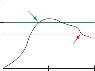
Thresh- Threshold and hysteresis work together to es- old and tablish the ON and OFF points of an analog in- Hyste- put. The threshold defines a trigger point or re- resis porting threshold (ON point) for a sensor input.
The hysteresis value establishes how much below the active threshold (ON point) an analog input is required to be before the input is consid-
rev. - |
www.bannerengineering.com - tel: 763-544-3164 |
13 |
crete I/ ple high and sample low parameters are used
O)to create a filter to avoid unwanted input transitions. The default value is 0, which disables this feature. The value range is 1 through 255.
Pulse The pulse width determines the length of time, Width in seconds, that a digital output is active (1) be-
fore returning to zero. Select 0 to disable this feature.
SureCross Web Configurator
ered OFF. A typical hysteresis value is 10% to 20% of the unit’s range.
|
ON point |
Value |
Threshold |
Input |
Hysteresis |
|
Input |
|
OFF point |
|
Time |
In the example shown graphically, the input is considered on at 15 mA. To consider the input off at 13 mA, set the hysteresis to 2 mA. The input will be considered off when the value is 2 mA less than the threshold.
Units Defined
The units parameter defines the range and/or type of data value associated with an input or output.
Selecting Units from within any configuration tool changes the units definition of several parameters, including threshold, hysteresis, and delta. For example, if the units are 0-20 mA, the threshold, hysteresis, and delta values are entered as milliampere values. Selecting Temp C changes the threshold, hysteresis, and delta units to degrees Celsius.
Signed values range from −32768 to +32767 and allow for the measurement of negative values. Signed values are typically used for measuring temperatures. Signed values are stored as two's complement values.
Unsigned values range from 0 to 65535 and are used to measure values that do not go below zero, such as 4 to 20 mA, distance, or a counter.
|
|
Input Units |
|
|
|
Units |
Description |
Definition |
|
|
|
0 |
Raw |
Displays the raw A/D conversion data with data ranges from 0 to 65535. This units type is typical- |
|
|
ly used only for factory calibration. |
|
|
LCD: Raw A/D hex value |
|
|
|
1 |
4 to 20 mA |
Analog unit. Modbus register contents are scaled such that 0 represents 4 mA and 65535 repre- |
|
|
sents 20 mA. |
|
|
LCD: 4.00mA–20.00mA |
|
|
|
2 |
0 to 20 mA |
Default analog input unit. Modbus register contents are scaled such that 0 represents 0 mA and |
|
|
65535 represents 20 mA. |
|
|
LCD: 0.00mA–20.00mA |
|
|
|
3 |
Discrete (ON/OFF) |
Default discrete input unit. |
|
|
LCD: ON/OFF |
|
|
|
4 |
0 to 10V (Volts) |
Analog input using 0 to 10V instead of current. Modbus register contents are scaled such that 0 |
|
|
represents 0V and 65535 represents 10V. |
|
|
LCD: 0.00V–10.00V |
|
|
|
14 |
www.bannerengineering.com - tel: 763-544-3164 |
rev. - |
SureCross Web Configurator
|
|
Input Units |
|
|
|
Units |
Description |
Definition |
|
|
|
6 |
Temp °C |
Celsius, high resolution. Analog input for temperature devices such as thermocouples, RTD, and |
|
|
thermistors. In high resolution mode, temperature = (Modbus register value) ÷ 20. |
|
|
LCD: 0000.0C |
|
|
|
7 |
Temp °F |
Fahrenheit, high resolution. Analog input for temperature devices such as thermocouples, RTD, |
|
|
and thermistors. In high resolution mode, temperature = (Modbus register value) ÷ 20. |
|
|
LCD: 0000.0F |
|
|
|
8 |
Temp °C (Low Res) |
Celsuis, low resolution. To measure a greater temperature range, use the low resolution unit. In |
|
|
low resolution mode, temperature = (Modbus register value) ÷ 2. |
|
|
LCD: 0000.0C |
|
|
|
9 |
Temp °F (Low Res) |
Fahrenheit, low resolution. To measure a greater temperature range, use the low resolution unit. |
|
|
In low resolution mode, temperature = (Modbus register value) ÷ 2. |
|
|
LCD: 0000.0F |
|
|
|
10 |
Asynchronous |
The 32-bit counter value records counts up to 4.29 billion. |
|
Counter, 32-bit |
LCD: 0000 0000 |
|
|
|
|
|
|
11 |
Asynchronous |
The 16-bit counter value records counts up to 65535. |
|
Counter, 16-bit |
LCD: 0000 |
|
|
|
|
|
|
|
|
Output Units |
|
|
|
Units |
Description |
Definition |
|
|
|
0 |
Raw |
Displays the raw A/D conversion data with data ranges from 0 to 65535. This units type is typical- |
|
|
ly used only for factory calibration. |
|
|
LCD: Raw A/D hex value |
|
|
|
1 |
4 to 20 mA |
Analog unit. Modbus register contents are scaled such that 0 represents 4 mA and 65535 repre- |
|
|
sents 20 mA. |
|
|
LCD: 4.00mA–20.00mA |
|
|
|
2 |
0 to 20 mA |
Default analog input unit. Modbus register contents are scaled such that 0 represents 0 mA and |
|
|
65535 represents 20 mA. |
|
|
LCD: 0.00mA–20.00mA |
|
|
|
3 |
Discrete (ON/OFF) |
Default discrete unit. |
|
|
LCD: ON/OFF |
|
|
|
4 |
0 to 10V (Volts) |
Analog unit using 0 to 10V instead of current. Modbus register contents are scaled such that 0 |
|
|
represents 0V and 65535 represents 10V. |
|
|
LCD: 0.00V–10.00V |
|
|
|
5 |
Signed Analog, 0 to |
For a signed value, such as temperature, that is to be converted to a voltage out value. Use null |
|
10V |
to set the start point and span to define the range. The null value is the starting temperature to be |
|
|
associated with 0V. The span is the entire temperature range that is to be associated with 0 to |
|
|
10V. |
|
|
LCD: 0.00V–10.00V |
|
|
|
rev. - |
www.bannerengineering.com - tel: 763-544-3164 |
15 |
|
|
SureCross Web Configurator |
|
|
|
|
|
Output Units |
|
|
|
Units |
Description |
Definition |
|
|
|
6 |
Signed Analog, 0 to |
For a signed value, such as temperature, that is to be converted to a mA out value. Use null to |
|
20 mA |
set the start point and span to define the range. The null value is the starting temperature to be |
|
|
associated with 0 mA. The span is the entire temperature range that is to be associated with 0 to |
|
|
20 mA. |
|
|
LCD: 0.00mA–20.00mA |
|
|
|
7 |
Unsigned Analog, 0 |
For unsigned values, such as a counter, that is to be converted to a mA out value. Use the null to |
|
to 20 mA |
set the start point and span to define the range. The null value is the distance to be associated |
|
|
with 0 mA. The span is the entire distance range that is to be associated with 0 to 20 mA. |
|
|
LCD: 0.00mA–20.00mA |
|
|
|
8 |
Signed Analog, 4 to |
In older models, this units type is for degree Celsius conversions only. Use null to set the start |
|
20 mA (A) |
point and span to define the range. The null value is the starting temperature to be associated |
|
|
with 4 mA. The span is the entire temperature range that is to be associated with 4 to 20 mA. For |
|
|
newer firmware models, type codes 8 and 9 are treated the same. |
|
|
LCD: 4.00mA–20.00mA |
|
|
|
9 |
Signed Analog, 4 to |
In older models, this units type is for degree Fahrenheit conversions only. Use null to set the start |
|
20 mA (B) |
point and span to define the range. The null value is the starting temperature to be associated |
|
|
with 4 mA. The span is the entire temperature range that is to be associated with 4 to 20 mA. For |
|
|
newer firmware models, type codes 8 and 9 are treated the same. |
|
|
LCD: 4.00mA–20.00mA |
|
|
|
10 |
Unsigned Analog, 0 |
For an unsigned value, such as 0 to 20 mA, that is to be converted to a voltage out value. Use the |
|
to 10V |
null to set the start point and span to define the range. The null value is the distance to be associ- |
|
|
ated with 0V. The span is the entire distance range that is to be associated with 0 to 10V. |
|
|
LCD: 0.00V–10.00V |
|
|
|
11 |
Counter, 16-bit |
The 16-bit counter value records counts up to 65535. |
|
|
LCD: 0000 |
|
|
|
12 |
Unsigned Analog, 4 |
For an unsigned value, such as 0 to 10V, that is to be converted to a mA out value. Use the null |
|
to 20 mA |
to set the start point and span to define the range. The null value is the distance to be associated |
|
|
with 4 mA. The span is the entire distance range that is to be associated with 4 to 20 mA. |
|
|
LCD: 4.00mA–20.00mA |
|
|
|
Battery Powered Sensor Options
Sensor Power Supply
Select a power supply for the sensor device. Select Supply 1 through 4 to indicate the external device is powered from one of the Node’s supplied switch power connectors.
External. The sensor is powered from outside the Node. Supply #1. Switched power 1 (SP1)
Supply #2. Switched power 2 (SP2) Supply #3. Switched power 3 (SP3) Supply #4. Switched power 4 (SP4)
16 |
www.bannerengineering.com - tel: 763-544-3164 |
rev. - |

SureCross Web Configurator
Supply Output Voltage
The Supply Output Voltage sets the voltage required for the sensor device. This parameter is only applicable when using the supplied switch power option.
Supply Warmup
Supply Warmup defines the length of time the switch power should be turned on before examining the sensor’s input.
Switch Power
Warmup Time
Voltage
0 Volts
Sample point |
Sample point |
Sample interval
I/O Linking
Each device input point can be linked or connected to any output point in the system. An output link defined as zero for the device and zero for the output point is not connected. Valid output points on all devices are nine through fourteen; valid devices are one through fifteen with zero reserved for the Gateway (or GatewayPro).
In the sample screen shown, the Gateway input points can be mapped to any Node’s outputs. Manually enter the device number in the Destination Device # box, then enter the I/O point number for that destination device.
After making changes to this screen:
1.Click on the Change button to send the changes to the DX83 Ethernet Bridge or the GatewayPro
2.Click on the Send button to send these changes to the device.
rev. - |
www.bannerengineering.com - tel: 763-544-3164 |
17 |
Change |
If you leave any Web Configurator screen with- |
|
out clicking the Change button to submit the |
|
changes to the Ethernet Bridge or GatewayPro, |
|
all changes are lost. |
Get |
Click the Get button to read all device and I/O |
|
parameters from the DX80 device and load |
|
them into the Web Configurator screens. This |
|
does not save the parameters to the XML file. |
Packed |
Setting the Packed flag communicates discrete |
Flag |
output point information more efficiently. Instead |
|
of sending one message for each output |
|
change, discrete values are packed into one |
|
message sent to the destination device. The |
|
packing data reduces the wireless device traffic |
|
and improves the timing in critical applications |
|
when multiple inputs from a single device are |
|
connected to outputs on one other device. |
|
The Packed flag only affects the output point |
|
messages, the input message communication is |
|
defined by each device I/O point. If a device I/O |
|
point Report Type parameter is defined as dis- |
|
crete, the input reporting messages for this |
|
point are packed into one wireless message. |
|
For greatest efficiency, all discrete inputs |
|
should be defined as a discrete Report Type. |
Prev |
If there are more than 16 devices or rules/maps, |
and |
use the Prev and Next buttons to display the |
Next |
next screen of information. |
|
SureCross Web Configurator |
Refresh |
Click the Refresh button to refresh the |
|
screen image. This updates any information |
|
on the screen that may have changed on the |
|
device. |
Reset |
The Reset button resets any error conditions |
|
displayed. Until the error message is reset, |
|
the device will not start any additional opera- |
|
tions. |
Saving |
To permanently save the changes to the |
Changes to XML file, go to the System > Setup > Config |
|
the XML |
File page and click the Save button. |
File |
Changes made by clicking an Update button |
|
are temporary and only submitted to the |
|
Ethernet Bridge or GatewayPro, not the XML |
|
file. |
Send |
Clicking the Send button transmits device |
|
and I/O parameters to the radio devices. The |
|
Send operation usually requires several sec- |
|
ond to complete. |
Scaling
The Scaling screen is used for converting data.
Raw data is multiplied by the Scale and added to the Offset to produce the data appearing in the floating point register associated with the I/O point. The floating point registers start at register 1001.
18 |
www.bannerengineering.com - tel: 763-544-3164 |
rev. - |

SureCross Web Configurator
For example, thermocouple inputs are multiplied by 20 before being written to the Modbus register. To convert this register value back to a temperature reading use the Scaling screen.
The Offset value can be used to account for errors introduced into the sensor system, such as errors introduced because of wiring lengths in a thermocouple input system.
Other Commands |
|
|
|
Prev and If there are more than 16 devices or rules/ |
Up- |
Clicking the Update button sends information to the |
|
Next |
maps, use the Prev and Next buttons to display |
date |
Ethernet Bridge or GatewayPro or retrieves infor- |
|
the next screen of information. |
|
mation depending on which checkboxes are selec- |
|
|
|
ted: Change or Get/Send All. Updating information |
|
|
|
does not save configuration information perma- |
|
|
|
nently to the XML file. |
Remote I/O
The Remote I/O configuration page defines up to 32 external communication registers when the DX80 Gateway is defined as a Modbus RTU Master.
This table is used only when the Gateway is a Modbus RTU master and it is communicating with Modbus slave devices, typically DX85 Expanded Remote I/O devices.
rev. - |
www.bannerengineering.com - tel: 763-544-3164 |
19 |

SureCross Web Configurator
After power-up, the DX80 Gateway is a slave device (to the Ethernet Bridge) for the time defined in the Master Timeout field, defined in seconds with a 90 second minimum. During this time, the operating mode can be changed using the browser interface. To change the mode:
1.Click one of the radio buttons to select how the DX80 Gateway functions.
•Select Modbus/TCP Client/Server mode (default) when you are connecting a DX80 to an external PLC or similar equipment.
•Select Modbus RTU Master mode if the DX80 Gateway is to be a Modbus master device communicating to other slave devices using a Modbus RS485 serial connection. The Gateway enters master mode after the Master Timeout period has elapsed.
•Select Modbus RTU Slave if the DX80 GatewayPro or a Ethernet Bridge and Gateway pair is operating as a slave on a Modbus serial connection.
2.Set the Master Timeout field, then click the Change Mode button. When the timeout expires, the DX80 Gateway begins to operate as selected. The Master Timeout determines how long the DX80 Gateway waits before changing modes.
3.After making changes, click on the Change button to send the changes to the DX83 Ethernet Bridge or the GatewayPro and then click on the Send button to send these changes to the device.
Saving Changes to the XML File
To permanently save the changes to the XML file, go to the System > Setup > Config File page and click the Save button. Changes made by clicking an Update button are temporary and only submitted to the Ethernet Bridge or GatewayPro, not the XML file.
Other Commands
Change If you leave any Web Configurator screen without clicking the Change button to submit the
Reset The Reset button resets any error conditions displayed. Until the error message is reset, the device will not start any additional operations.
20 |
www.bannerengineering.com - tel: 763-544-3164 |
rev. - |
SureCross Web Configurator
|
changes to the Ethernet Bridge or GatewayPro, |
Send Clicking the Send button transmits device and I/O |
|||
|
all changes are lost. |
|
|
parameters to the radio devices. The Send opera- |
|
Get |
Click the Get button to read all device and I/O |
tion usually requires several second to complete. |
|||
|
|||||
|
parameters from the DX80 device and load them |
|
|||
|
into the Web Configurator screens. This does not |
|
|||
|
save the parameters to the XML file. |
|
|
||
Refresh |
Click the Refresh button to refresh the screen |
|
|||
|
image. This updates any information on the |
|
|||
|
screen that may have changed on the device. |
|
|||
DX80 Modes |
|
|
|
|
|
|
|
|
|
|
|
Setting |
|
Gateway |
GatewayPro |
Ethernet |
|
|
|
|
|
Bridge |
|
DX80 is Modbus/ |
Slave |
Master |
Master |
Default mode. The Gateway is a Modbus slave device and the Ether- |
|
TCP Client/Server |
|
|
|
net Bridge is the master device. |
|
(default) |
|
|
|
|
|
|
|
|
|
|
|
DX80 is Modbus |
Master |
Master |
Ignored |
The Ethernet Bridge can only communicate with a slave device. In |
|
RTU Master |
|
|
|
this mode, any communications sent to the Bridge from the Web |
|
|
|
|
|
|
Configurator is ignored. To resume communications, cycle power to |
|
|
|
|
|
the Gateway. When power is cycled, the Ethernet Bridge begins |
|
|
|
|
|
again as a master device until the timeout lapses. |
|
|
|
|
|
|
DX80 is Modbus |
Slave |
Slave |
Ignored |
Similar to the default mode, but a device other than the Ethernet |
|
RTU Slave |
|
|
|
|
Bridge acts as the Modbus master device. The Ethernet Bridge still |
|
|
|
|
|
communicates with the Gateway and can read and write to registers, |
|
|
|
|
|
but another device is the master device. |
|
|
|
|
|
|
DX80 is a Modbus/TCP Client/Server (default)
The default configuration is DX80 is Modbus/TCP Client/Server. The DX83 Ethernet Bridge is the Modbus master device and only communicates with the device configured as Slave ID 1: the Gateway.
rev. - |
www.bannerengineering.com - tel: 763-544-3164 |
21 |

SureCross Web Configurator
1.Node 1, registers 17 through 32.
2.Node 2, registers 33 through 48.
3.Node 3, registers 49 through 64.
4.Gateway, Slave ID 1, registers 1 through 16.
5.DX83 Ethernet Bridge
DX80 Gateway is Modbus RTU Master
When a DX80 Gateway is set up as a Modbus RTU master device, the communication between the DX83 Ethernet Bridge (used to configure the network) and the Gateway is ignored. The Gateway acts as the Modbus RTU master device for the system, which may include other slave Gateways or DX85 Remote I/O slave devices. All communication must go through the master device.
The master table entries define the register-to-register communication for remote I/O points. Each line represents a register/point connection between the master device and a Modbus slave device with up to 32 table entries possible. For each table entry, specify the local Modbus register, action to perform, type of external point, external register number, external slave number, and a Modbus timeout value for that register access. Active threshold and hysteresis are optional parameters that may be applied to registers.
After making changes:
1.Click on the Change button to send the changes to the DX83 Ethernet Bridge or the GatewayPro.
2.Click on the Send button to send these changes to the radio devices.
3.To save the changes to the XML file, go to the System > Setup > Config File page and click the Save button.
This sample network shows a DX80 Gateway as the Modbus RTU Master device. Once the Gateway is set as the master, communication is ignored between the Ethernet Bridge (normally the master) and the Gateway.
22 |
www.bannerengineering.com - tel: 763-544-3164 |
rev. - |

SureCross Web Configurator
1.DX83 Ethernet Bridge
2.Slave ID 2, DX85 Modbus RTU Remote I/O
3.Node 1, registers 17 through 32
4.Master Device, DX80 Gateway, registers 1 through 16.
5.Node 2, registers 22 through 48.
6.Node 3, registers 49 through 64.
7.Slave ID 5, DX80 Gateway, registers 1 through 16.
8.Node 2, registers 33 through 48
9.Node 1, registers 17 through 32.
rev. - |
www.bannerengineering.com - tel: 763-544-3164 |
23 |

Parameters
Action |
Select an action from the following: None, Reads |
|
From, or Writes To. Select None to perform no |
|
action, Reads From reads the parameter from |
|
the remote register and copies the contents into |
|
the local register, and Writes To writes the data |
|
from the local register to the remote register. |
Get |
Click the Get button to read all device and I/O |
|
parameters from the DX80 device and load them |
|
into the Web Configurator screens. This does not |
|
save the parameters to the XML file. |
Local |
The Local Register entry is the from register in |
Regis- |
the I/O mapping. I/O points are linked from the |
ter |
local register to the remote register. |
Map |
Each map entry is defined with a map number, |
Num- |
one through 32. The master table entries define |
ber |
the register-to-register communication for remote |
|
I/O points. Each line represents a register/point |
|
connection to another Modbus slave device. Up |
|
to 32 table entries are possible. |
Poll |
The poll timeout refers to the time limit, in milli- |
Time- |
seconds, to communicate with a specific slave |
out |
device. When this time limited is exceeded, the |
|
system begins communicating with the next de- |
|
vice in the table. The Poll Timeout setting pre- |
|
vents the system from stopping when a slave de- |
|
vice is not responding. |
Re- |
Click the Refresh button to refresh the screen im- |
fresh |
age. This updates any information on the screen |
|
that may have changed on the device. |
Re- |
The Remote Register entry is the to register in |
mote |
the I/O mapping. I/O points are linked from the |
Regis- |
local register to the remote register. |
ter |
|
Re- |
Select a type from the following drop-down list: |
mote |
none, coil (output), discrete input, input register, |
Type |
or holding register. DX80 device registers are all |
|
holding registers. Banner Engineering’s Sure- |
|
Cross™ slave devices use only input registers |
|
and holding registers. When using slave devices |
|
from other manufacturers, please refer to the |
|
manufacturer’s documentation to determine what |
|
I/O types they use. |
|
Coil (output). 1xxxx - Other slave devices, write |
|
only, 1 bit |
|
Discrete Input. 3xxxx - Other slave devices, |
|
read only, 1 bit |
|
Input Register. 3xxxx - SureCross™ slave devi- |
|
ces, read only, 16 bit |
SureCross Web Configurator
Reset The Reset button resets any error conditions displayed. Until the error message is reset, the device will not start any additional operations.
Slave The slave ID is an identifying number used for ID devices within a Modbus system. By default,
Gateways are set to Modbus Slave ID 1. When using more than one Modbus slave, set each slave to a unique ID number.
Thresh- Threshold and hysteresis work together to es- old and tablish the ON and OFF points of an analog in- Hyste- put. The threshold defines a trigger point or re- resis porting threshold (ON point) for a sensor input.
The hysteresis value establishes how much below the active threshold (ON point) an analog input is required to be before the input is considered OFF. A typical hysteresis value is 10% to 20% of the unit’s range.
|
ON point |
Value |
Threshold |
Input |
Hysteresis |
|
Input |
|
OFF point |
Time
In the example shown graphically, the input is considered on at 15 mA. To consider the input off at 13 mA, set the hysteresis to 2 mA. The input will be considered off when the value is 2 mA less than the threshold.
24 |
www.bannerengineering.com - tel: 763-544-3164 |
rev. - |

SureCross Web Configurator
Holding Register. 4xxxx - SureCross slave devices, read/write, 16 bit
Selecting None for remote type negates the rule though it remains in the list until deleted. Unused rules at the end of the list always show None as the remote type.
DX80 is Modbus RTU Slave
The third option, DX80 is Modbus RTU Slave, sets up a Gateway and Ethernet Bridge or GatewayPro as a slave device. This selection stops the communication between the Ethernet interface and the DX80 Gateway.
DX80 is Modbus RTU Slave mode was created for special configurations of GatewayPro or Ethernet Bridge devices. Contact Banner Wireless Support for more information.
Network Tab
Use the Network main tab to configure the communications outside the radio network.
Modbus Data Submenu
The Ethernet processor in a GatewayPro or Ethernet Bridge can serve as a Modbus master device. The tables configured under the Network page define the Master communication settings for Modbus RTU and Modbus/TCP clients and servers. Use the Modbus Data submenu to view Modbus register data defined under the Modbus RTU set-up page.
RTU Registers
The RTU Registers screen displays the Modbus register contents for RTU slave devices defined under the Modbus RTU set-up page.
To change the register data:
1.Enter a new register data value
2.Select the Update checkbox.
3.Click the Update button to send the new data to the device.
Hex check- Select the Hex checkbox to view the data in box hexidecimal form (not recommended for
floating point values).
Prev and If there are more than 16 devices or rules/ Next maps, use the Prev and Next buttons to dis-
play the next screen of information.
Unit + and Scrolls through the list of RTU slave devices.
Unit–
Update Clicking the Update button sends information to the Ethernet Bridge or GatewayPro or retrieves information depending on which checkboxes are selected: Change or Get/ Send All. Updating information does not save
rev. - |
www.bannerengineering.com - tel: 763-544-3164 |
25 |
Loading...