


Users Manual
Snap 700 Linear Knife
Addendum
AVERY DENNISON
Manual Edition 2.2
7 February 2014
Manual Part Number 621395

WARNING
This device complies with Part 15 of the FCC Rules. Operation is subject to the following two conditions:
1)this device may not cause harmful interference, and
2)this device must accept any interference that may cause undesired operations.
This Class A digital apparatus meets all requirements of the Canadian Interference
Causing Equipment Regulations. Cet appareil numerique de la classe A respecte toutes les exigences du Reglement sur le material broilleur du Canada
ii |
Snap Linear Knife |
Contents |
|
Scope |
5 |
Introduction................................................................................................................................ |
5 |
Safety Issues / Warnings |
5 |
Cautions ..................................................................................................................................... |
5 |
Warranty Information |
6 |
Warranty Policy ......................................................................................................................... |
6 |
Service ......................................................................................................................... |
7 |
Description / Specifications |
8 |
Linear Knife Description ........................................................................................................... |
8 |
Linear Knife Specifications ....................................................................................................... |
8 |
Installing Linear Knife – See Appendix A |
9 |
Threading |
9 |
Maintenance |
10 |
Cleaning Feed / Nip Rollers..................................................................................................... |
10 |
Knife Blade Replacement ........................................................................................................ |
11 |
Knife Blade Cleaning............................................................................................................... |
15 |
Adjustments |
18 |
Web Tracking in Center of Printer........................................................................................... |
18 |
Setting the Web Tracking .......................................................................................... |
18 |
Setting the Web Guide............................................................................................... |
19 |
Knife Cam Adjustment ............................................................................................................ |
20 |
Web Tracking Adjustment ....................................................................................................... |
21 |
Adjusting the Sensor ................................................................................................................ |
23 |
Positioning the Sensor.............................................................................................................. |
26 |
Centering the Knife to the Web ............................................................................................... |
29 |
Trouble Shooting |
33 |
Appendix A |
35 |
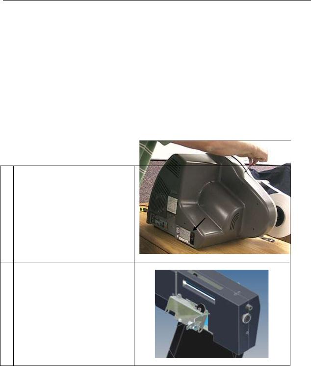
Removing the Stacker .............................................................................................................. |
35 |
Removing the Nip Assembly ................................................................................................... |
36 |
Removing the Knife Assembly ................................................................................................ |
37 |
Removing the Rear Cover........................................................................................................ |
39 |
Installing the Linear Knife - Electrical Updates....................................................................... |
40 |
|
|
|
Snap Linear Knife |
iii |
|
Replace the Motherboard Entry ................................................................................. |
40 |
Install Internal Harnesses........................................................................................... |
44 |
Installing the Linear Knife – Mechanical Updates................................................................... |
46 |
Installing the Lower Frame Support for the Linear Knife ......................................... |
46 |
Installing Linear Knife onto the Lower Frame Support............................................. |
47 |
Making Electrical Connections.................................................................................. |
49 |
Installing the Nip Assembly..................................................................................................... |
50 |
Installing the Stacker on the Linear Knife ............................................................................... |
52 |
Assembly Drawings |
55 |
Linear Knife Assembly Drawing ............................................................................................. |
56 |
Nip Roller Assembly Drawing................................................................................................. |
57 |
Drive Train Assembly Drawing ............................................................................................... |
58 |
Feed Roller Assembly Drawing ............................................................................................... |
59 |
Sensor Assembly Drawing....................................................................................................... |
60 |
Mounting Assembly Drawing .................................................................................................. |
61 |
Cover Assembly Drawing ........................................................................................................ |
62 |
Cover Assembly Drawing ........................................................................................................ |
63 |
Harnesses ................................................................................................................................. |
64 |
Linear Knife Parts List............................................................................................................. |
67 |
Linear Knife Parts List............................................................................................................. |
68 |
Linear Knife Parts List............................................................................................................. |
69 |
|
|
|
iv |
Snap Linear Knife |
|

Scope
Introduction
This manual details the installation, operation, and maintenance of the AVERY DENNISON Model SNAPTM700 Linear Knife. Use this manual together with the SNAPTM700 User Manual for other operational questions regarding the SNAP 700 printer itself.
Safety Issues / Warnings
Cautions
The Linear Knife uses very sharp cutting blades that are spring-loaded together. The knife also has a well-guarded pinch points. The guarded covers provided with the knife are for operator protection. Under no circumstance should the covers be removed during operation.
Covers provide other functions beside safety. They affect cut quality and provide strength to the knife assembly.
Snap Linear Knife |
Scope 5 |

Warranty Information
Warranty Policy
Avery Dennison Retail Branding & Information Solutions provides the following warranty policy.
Scope
Warranties against defects from workmanship for equipment and parts manufactured and sold from Miamisburg, OH. Includes time and material except as otherwise noted below.
Time
New equipment and parts: 1 year return to depot
Refurbished equipment and parts: 90 days
Warranty period starts when equipment ships from selling location.
General Conditions
Avery Dennison extends warranty coverage under the following conditions.
Equipment and parts will perform within published specifications. Promised or implied statements by any Avery Dennison employee or representative will not be deemed to vary the terms of the warranty.
Equipment and parts must be installed and operated according to recommended procedures and operating conditions.
Consumable elements are not covered. Consumable elements are those that show normal wear from typical equipment usage including, without limitation, print heads, knives, rollers in contact with the web, and sonic units. Avery Dennison reserves the right to determine which elements are defined as “consumable.”
No customer maintenance may be performed except as directed by qualified Avery Dennison personnel.
Equipment and parts damaged by negligence or abuse are not covered.
Avery Dennison US reserves the right in its sole Linearretion to incorporate any modifications or improvements in the machine system and machine specifications which it considers necessary but does not assume any obligation to make said changes in equipment previously sold.
Equipment Purchased In US and Shipped In US
Avery Dennison US covers warranty for equipment and parts installed and operated in the Americas (United States, Canada, Mexico, Central America, Caribbean Region, and South America excluding Brazil).
Outside the US, the local Avery Dennison office is responsible for equipment and parts warranty. Customers must ensure coverage during machine purchase.
|
|
|
6 Warranty Information |
Snap Linear Knife |
|
Equipment purchased and exported to regions outside local Avery Dennison office coverage are not covered by warranty. The purchasing agent must acquire a service contract from the Avery Dennison office where the equipment or parts are operated to ensure machine coverage. For example, if an agent purchases a printer in the US, exports to Brazil, and then needs warranty coverage, Avery Dennison Brazil has no obligation to provide warranty coverage. The agent must purchase services from Avery Dennison Brazil.
THE WARRANTIES PROVIDED HEREIN ARE EXCLUSIVE AND ARE IN LIEU OF ANY IMPLIED WARRANTY OF MERCHANTABILITY, FITNESS FOR A PARTICULAR PURPOSE OR OTHER WARRANTY OF QUALITY OR PERFORMANCE, WHETHER EXPRESS OR IMPLIED. EXCEPT THE WARRANTY OF TITLE, IN NO EVENT SHALL AVERY DENNISON BE LIABLE FOR ANY INDIRECT, INCIDENTAL OR CONSEQUENTIAL DAMAGES, EVEN IF AVERY DENNISON HAS BEEN ADVISED OF THE POSSIBILITY OF SUCH DAMAGES.
Service
When ordering machines and supplies in the U.S.A., reference all correspondence to the address below.
AVERY DENNISON Corporation
170 Monarch Lane
Miamisburg, OH 45342
Call: 1-800-214-0872 or (937) 865-2123
For spare parts, requests for service or technical support, contact
AVERY DENNISON Corporation
170 Monarch Lane
Miamisburg, OH 45342
Call: 1-800-214-0872 or (937) 865-2123
For parts and service in other countries, please contact your local AVERY DENNISON supplier.
|
|
|
Snap Linear Knife |
Warranty Information 7 |
|

Description / Specifications
Linear Knife Description
The SNAP Linear Knife is an add-on accessory for the SNAP 700 printer. It mounts in place of the down stacker and in turn provides a mounting for the down stacker.
The Linear Knife is designed to cut tag stock and stack into the down stacker. It does not work with flimsy material such as care label tapes or pressure sensitive materials.
The Linear Knife is removable if the other materials need to be processed on the printer using the rotary knife. A training technician is required because the entry into the printer electronics is required.
Linear Knife Specifications
Label Size |
Length: Min 1 1/2” (38.10mm) Max (See Printer Specs) |
|
Width: Min: 1 1/2” (38.10 mm) TESTED, Max: 5 1/8" (130.18 mm) wide web |
|
|
Print Speed |
3ips, 4ips, 4.5ips, 5ips, 6ips, (RFID 2ips and 3ips) TESTED |
|
|
Web Justification |
Center |
|
|
Stock |
Coated and uncoated Tag Stock and RFID tag stock 10 point to 15 point TESTED |
|
|
Cleaning |
RFID supplies require knife blade cleaning every 25,000 cuts based on supply adhesive construction |
|
|
Dimensions |
11.00" (279.40 mm) wide x 17.25" (438.15 mm) deep x 18.00" (457.20 mm) high |
|
|
Weight |
34 Lbs. (15.5Kg.) |
|
|
Electrical |
DC Power, source is from the SNAP 700 Printer |
|
|
Temperature |
55°F - 95°F (12.7°C to 35°C) |
|
|
Humidity |
5% - 90% non-condensing without corrosion to finish |
|
|
Registration |
Blank stock, 1/16”(1.5mm) to 1/8” (3mm) hole, notch 1/16”(1.5mm) min., top reflective, |
System |
bottom reflective (80% contrast). |
|
Hole or reflective mark can be any were across the web. |
|
|
Options |
N/A |
|
|
|
|
|
8 Description / Specifications |
Snap Linear Knife |
|
Installing Linear Knife – See Appendix A
See Appendix A for Linear Knife Installation Instructions.
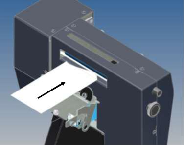
Threading
To thread the stock through the SNAP 700 Linear Knife, bring the stock up to the entry point of the knife. Once the stock comes in contact between the upper and lower rollers, turn the feed knob clockwise. The stock will traverse through the knife and exit out the nip assembly.
You will need to rotate both the printer feed knob and the linear knife feed knob. The feed on the linear knife will not pull the material through the printer. The feed in the linear knife is for take-up tension only.
|
|
|
Snap Linear Knife |
Installing Linear Knife – See Appendix A 9 |
|

Maintenance
Cleaning Feed / Nip Rollers
The Linear Knife has a set of feed rollers that keep web tension between the printer feed and the accessory knife. These rollers will need cleaning daily or more often based on the materials being run,
1.Clean the rollers with isopropyl rubbing alcohol 70%. Do not use other cleaning products as they may have a long term effect to roller life.
2.Turn off the power to the printer to clean any moving part to avoid injury or damage to the printer
3.Apply the alcohol to a clean cloth and rub the rollers to remove any surface build up. The rubber roller may become stained for contact with the materials running through the printer. This should not harm the roller or the material.
4.The rubber roller should be replaced at least once a year or before due to ware or if the rubber starts to harden from age or UV lighting.
|
|
|
10 Maintenance |
Snap Linear Knife |
|
Knife Blade Replacement
|
Replace the wheel blade when it becomes dull or nicked. The knife has a life |
||
|
expectancy of 3 million cuts. Monitor the number of cuts through PCMate since |
||
|
the printer does not have a cut counter. Stock both the wheel and stationary |
||
|
blades to avoid down time in case of blade damage or jams. |
||
|
Note: Replace both the wheel blade and the stationary blade as a set only. |
||
|
Replacing only one can cause early failure of the blades. |
||
|
|
|
|
|
|
Warning: Follow knife adjustment procedure exactly |
|
|
|
or damage will occur. |
|
|
Warning: Turn off power to the printer to avoid |
|
|
|
|
personal injury when adjusting, removing, or |
|
|
|
replacing the knife assembly. |
|
|
|
|
|
When following |
are |
very sharp. |
|
1.Turn off power to the printer.
2.Remove the feed knob and the sensor adjust knob.
|
|
|
Snap Linear Knife |
Maintenance 11 |
|
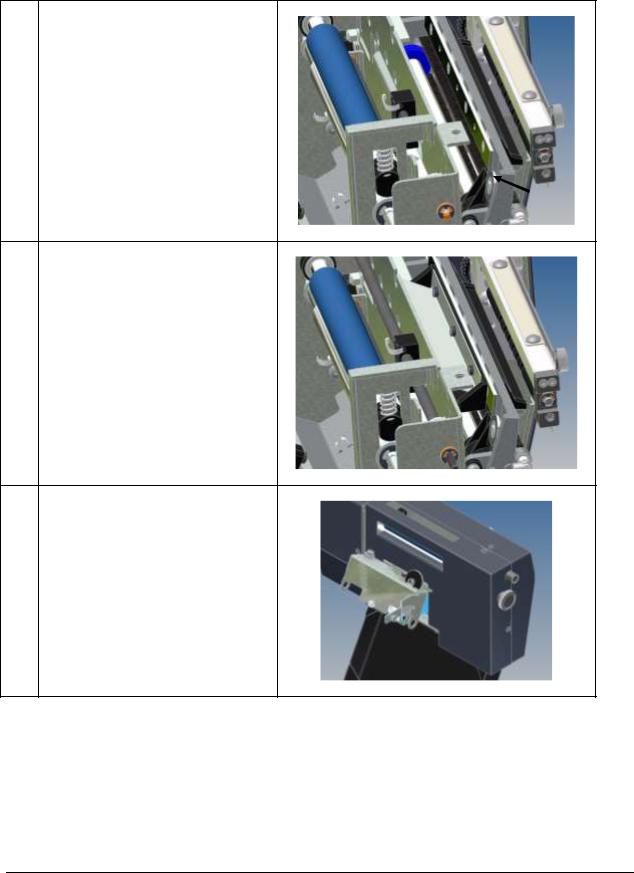
3.Remove the six 8-32 Button Head Screws and remove the left and right side covers.
4.Remove the entry guide and deflector bracket by swinging the carriage assembly out and inserting a 2.5mm Allen Key or ball driver through the holes in the frame to gain access to the screws.
Note: The upper sensor shaft is not shown for clarity purposes.
5.With the entry guide removed, see the four exposed Phillips flat head screws holding the upper stationary blade. Remove screws and blade with a #2 Phillips head screw driver.
12 Maintenance
Snap Linear Knife
6.Removing the upper stationary blade allows access to the wheel blade. Remove the wheel blade, bearing, and spacer. Replace the new parts in same order as removed and shown.
Note: Be careful not to move the carriage assembly too much as the wheel blade will fall off.
7.Re-install the upper stationary blade with the four flat head screws removed from step 5.
Be sure the wheel blade is behind the Stationary Blade and that the stationary blade is oriented so that the cutter edge is down.
8.Re-install the deflector bracket and entry guide.
Snap Linear Knife
Maintenance 13
9.Re-install the covers and knobs.
|
|
|
14 Maintenance |
Snap Linear Knife |
|
Knife Blade Cleaning
When the material starts to have poor cut along all or part of the cut edge, the knife blades will need to be removed and cleaned.
Note: When cutting RFID tag stock the knife may need to be cleaned every 25,000 cuts depending on the adhesive layer used to construct the tag material. This may vary in frequency base on the supplies. The knife blades will need to be taken apart as surface cleaning is insufficient.
|
|
Warning: Follow knife adjustment procedure exactly |
|
|
|
or damage will occur. |
|
|
Warning: Turn off power to the printer to avoid |
|
|
|
|
personal injury when adjusting, removing, or |
|
|
|
replacing the knife assembly. |
|
|
|
|
|
|
When following |
are |
|
|
very sharp. |
|
|
1.Turn off power to the printer.
2.Remove the feed knob and the sensor adjust knob.
|
|
|
Snap Linear Knife |
Maintenance 15 |
|

3.Remove the six 8-32 Button Head Screws and remove the left and right side covers.
4.Remove the entry guide and deflector bracket by swinging the carriage assembly out and inserting a 2.5mm Allen Key or ball driver through the holes in the frame to gain access to the screws.
Note: The upper sensor shaft is not shown for clarity purposes.
5.With the entry guide removed, see the four exposed Phillips flat head screws holding the upper stationary blade. Remove screws and blade with a #2 Phillips head screw driver.
Clean the blade with Isopropyl Alcohol. The blades are very sharp. Cut resistant gloves should be worn to avoid injury.
6.With the upper stationary blade removed there is access to the disc blade. Remove the disc blade. The bearing and spacer can stay on the carriage assembly.
Clean the disc blade with isopropyl alcohol.
Replace blade in same order as removed.
Note: Be careful not to move the carriage assembly too much as the disc blade will fall off.
16 Maintenance
Snap Linear Knife
7.Re-install the upper stationary blade with the four Phillips flat head screws removed from step 5.
Be sure the wheel blade is behind the stationary blade and that the stationary blade is oriented so that angle is down.
8.Re-install the deflector bracket and entry guide.
9.Re-install the covers and knobs.
Snap Linear Knife
Maintenance 17
Adjustments
Web Tracking in Center of Printer
NOTE: Cut quality and straightness requires the stock to track down the center of the printer because the Linear Knife cuts across the web from both sides. Two settings adjust web tracking. The first setting is moving the web front to back as controlled by the Feed Roller Assembly. The second setting is the position of the Web Guide Assembly.
The Linear Knife makes one pass across the web for each tag cut. This means that if the knife starts its cut from the near side of the web and the next cut starts from the far side of the web. The cut is done while the web is moving through the printer. The knife has been designed when properly installed to be located in the center of the feed roller assembly and the print head assemblies. If one or both of these setting are not correct the cut will vary in width every other cut.
Setting the Web Tracking
Web tracking is the movement of the tag stock front to back in the Feed Assembly. To correct for this movement there are four “Jack” Set Screws located on the inner mount bracket on the Feed Assembly. These will be adjusted accordingly once the printer has been loaded with stock and run.
1.Load the printer with supplies (Stock & Ink) Make sure the tag stock supply roll is tight and the sides of the roll are flat. If the roll is not flat it will track off the center of the print heads.
2.Leave the web guide open so the guides do not control the material moving through the printer.
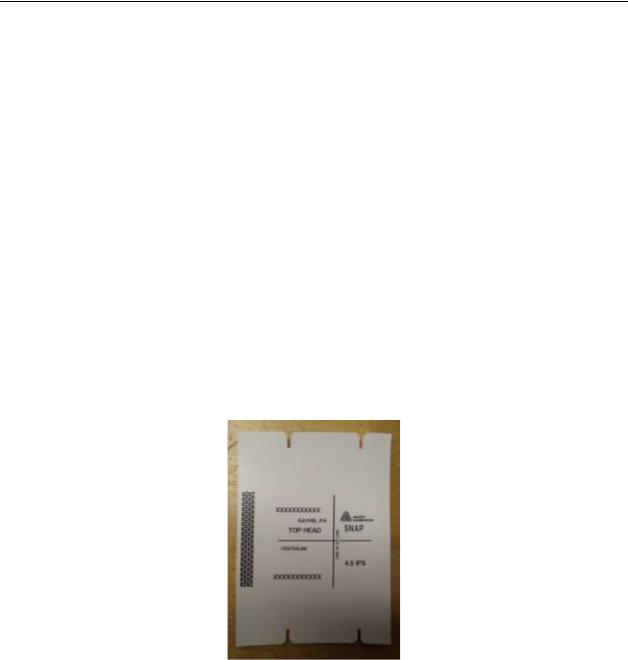
3.Load the internal test format (see SNAP 700 user manual). The wide test format image will look like this. The line running left to right should be in the center of the tag. The center of the line to the metal frame is
4” (101.6mm).
4.Start the printer, if the stock is walking toward the back of the printer, the outboard end of the Feed
Assembly needs to move toward the stacker. (Don’t worry if the knife cut is out of square, this will be corrected later)
5.Loosen the three ¼-20 cap screws and turn the two left set screws 1/8 of a turn so that it will force the outer end to move toward the stacker.
6.Snug the ¼-20 cap screws starting with the Upper right, then the lower, then the upper left.
7.Once all are snug, tighten the cap screws in the same order.
|
|
|
18 Adjustments |
Snap Linear Knife |
|
8.Run the printer again and see if there is a walking issue, if so repeat steps 4-6.
9.If the stock wants to walk toward the front of the printer, then position the feed assembly so that the outer edge move slightly away from the stacker side, and reverse steps as previously stated.
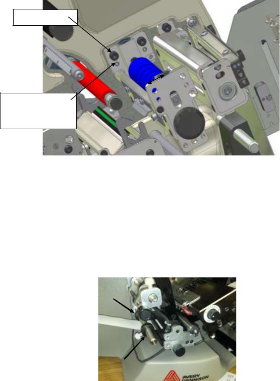
Loosen Screws
Use “Jack” Set
Screws to position the Feed Assembly one way or the other.
10.Once the stock is tracking through the printer without walking, the feed assembly can be secured.
11.The Printer is now ready for the latest Operating System Installation. Download and install Operating System Version 3.32.07.05 or later.
Setting the Web Guide
The web guide is located between the tag stock supply roll and the first print station in the web path. To set the web guide correctly, get the tracking of the printer centered first. There are two set collars with thumbs screws that will rest just off the material. Position these collars to steer the web correctly through the printer. Do not try and force the stock more then 1/4” (5mm) as it can damage the edge of the tag stock.
|
|
|
Snap Linear Knife |
Adjustments 19 |
|
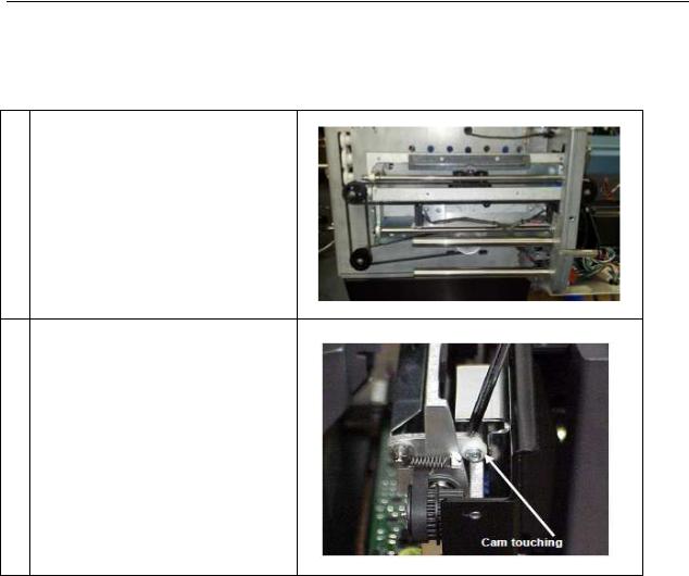
Knife Cam Adjustment
The cam adjustment keeps the frame from distorting during operation and affects the cut angle slightly.
1.Move the rotary knife carriage to the center of the stationary knife.
2.Adjust the inboard and outboard cam to just barely touch the frame. Hold the came in the desired position while tightening the screws.
|
|
|
20 Adjustments |
Snap Linear Knife |
|
Web Tracking Adjustment
If the web is tracking through the SNAP 700 printer but is not tracking into the Knife square, there will be a buckle in the web. The tracking can be adjusted by rotating the thumb wheel on the Linear Knife located on the inboard side of the Knife.
Buckle in Rear of Knife (Needs to be adjusted, cut will not be
square.)
Web tracking straight (No buckle)
Ready to move to the next step
Buckle in Front of Knife (Needs to be adjusted, cut will not be
square.)
|
|
|
Snap Linear Knife |
Adjustments 21 |
|
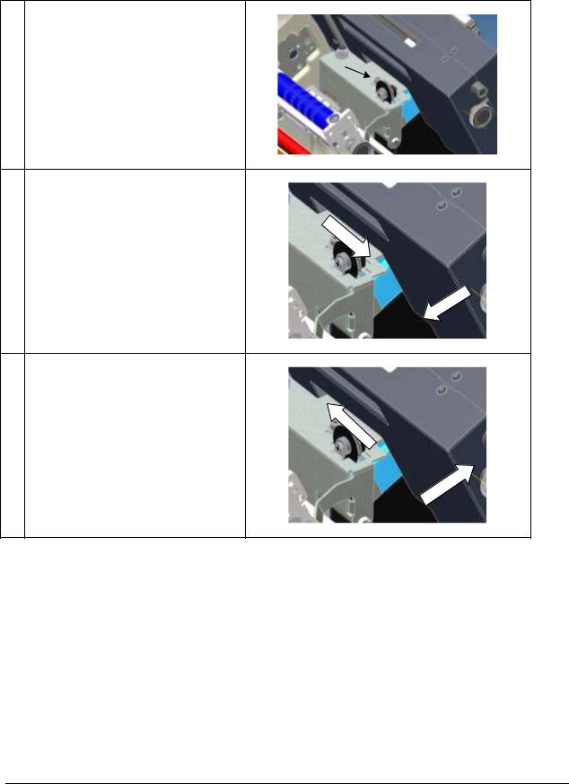
1.Loosen the ¼-20 cap screw shown. Rotating the thumb wheel will rotate the knife in one direction or the other.
2.Rotate the thumb wheel toward the operator to move the outer edge of the knife to the left.
3.Rotate the thumb wheel away from the operator to move the outer edge of the knife to the right.
After the knife is in the desired location, tighten the ¼-20 cap screw.
22 Adjustments
Snap Linear Knife
 Loading...