


A64 CS Stacker Quick Reference
This Quick Reference contains supply loading information, setup, general care, and maintenance procedures for the Avery Dennison® A64 Cutter/Stacker. For more detailed information, refer to the Operator’s Handbook available on our Web site (www.monarch.com).
Information in this document supercedes information in previous versions. Check our Web site for the latest documentation and release information.
Warning:
This equipment generates, uses, and can radiate radio frequency energy and if not installed and used in accordance with the instruction manuals, may cause interference to radio communications. It has been tested and found to comply with the limits for a Class A computing device pursuant to Subpart J of Part 15 of FCC Rules, which are designed to provide reasonable protection against such interference when operated in a commercial environment. Operation of this equipment in a residential area is likely to cause interference in which case the user, at his own expense, will be required to take whatever measures may be required to correct the interference.
G e t t i n g S t a r t e d
1.Set up your printer. Refer to the documentation provided with your printer for more information.
2.Unpack the stacker and packing material from the box. The box should contain:
•Stacker base and tray assembly (with the “Stacker Full” cable attached to tray)
•Power cord and stacker interface cable
3.Set the stacker to the left side of the printer.
4.Alignment the printer to the stacker.
5.Attach the stacker tray assembly.
•Align the slotted holes of the tray with the studs on the stacker base.
•Align the fingers of the tray with grooves on the top rollers.
•Center the two screw holes and start the captive screws from underneath the base. Make sure the tray fingers do not touch the black transport roller.
•Tighten the screws.
Slotted Holes
Studs |
Studs |
|
Underside of Tray Screw Holes Captive Screws Top view of Base
|
|
|
TC9864CSQR Rev. AA 6/08 |
©2008 Avery Dennison Corp All rights reserved. |
|

6.Connect the stacker full cable and stacker communication cable between the stacker and your printer.
7.Plug the power cord to the stacker and the other end into a grounded electrical outlet.
Communication Cable
Communication Cable
Connector
Connector
Stacker Full Cable
 Power Cord
T h r e a d i n g S u p p l y
1.Make sure the stacker is disabled. The stacker is disabled when the READY light is red.
2.Threading tags between tag guides:
•Thread tags under the dancer rollers and push against the fixed guide.
• Slide the outer tag guide towards the tags leaving  space between the guides for the tags to move freely. Dancer Rollers
3. Set the pusher tag width: |
Outer Guide |
Outer Guide
Fixed Guide
Sample Tag
• Loosen the thumbscrew on the outer tag
pusher. |
Thumbscrew |
|
|
|
|
• Place a sample tag between the guides and |
|
|
slide the outer guide towards the tag leaving |
|
|
space between the guides for the tags to |
|
|
move freely. |
|
|
• Tighten the thumbscrew. |
|
|
4. Adjust the tag stack support bar: |
|
Thumbscrew |
• Loosen the thumbscrew on the tag support bar. |
|
|
•Slide the bar left or right to the middle of the tags.
•Tighten the thumbscrew.
Sample Tag
2
5.Adjust the side bar guide:
•The side bar is attached with magnets.
•Align the side bar with the notch of the outer tag
pusher. Make sure the side bar is parallel to the edge of the tray.
Note: Adjust the sensors if you use tags with a |
Side Bar Guide |
Notch |
|
notch, swiftach hole, or a flag document. |
|||
|
|
See “Making Sensor Adjustments” for more information.
6. Press START/STOP to enable the stacker.
The READY light is green when the stacker is enabled and ready to cut and stack tags. When the printer begins printing, the stacker automatically feeds, cuts, and stacks the tags.
Note: After pressing START/STOP, if the stacker does not see the notch or sensor mark within 16 inches of supply, the stacker automatically disables and the READY light turns red.
M a k i n g S e n s o r A d j u s t m e n t s
The stacker uses three types of sensors: the transmissive sensor, the flag sensor, and the reflective sensor. Test sensors by feeding tags through the stacker. To feed tags, disable the stacker and advance tags by manually turning the feed roller. If the NOTCH light does not light, the sensors may need to be adjusted.
Setting the Transmissive Sensor
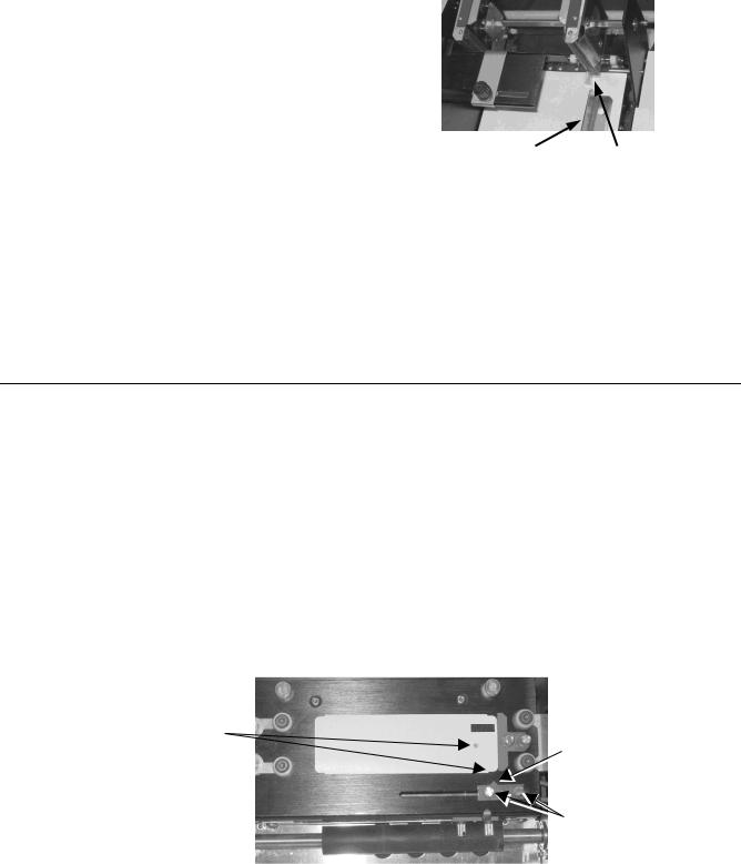
The transmissive sensor is located on the front of the knife assembly and is used for cutting tags with a notch or a Swiftach hole.
Note: When the position of the transmissive sensor is set correctly, the NOTCH light flashes as tags pass the sensor.
•Make sure the stacker is disabled. The stacker is disabled when the READY light is red.
•Place a sample tag against the guide on the knife assembly.
•Loosen the sensor thumbscrews and slide it until the arrow is pointing to the notch or hole.
•Tighten the thumbscrews.
Align Arrow with
Arrow
Notch or Hole
Thumbscrews
3
 Loading...