


ALS 230
Table of contents
 Loading...


Operators Manual
ALS 230
Release 11/05 Page i Contents
Contents
1. Important Notes........................................................................................................4
1.1 Overview.......................................................................................................................................4
1.1.1 Manufacturer......................................................................................................................4
1.1.2 Copyright............................................................................................................................ 4
1.2 Safety............................................................................................................................................ 5
1.2.1 General Safety Notes ........................................................................................................ 5
1.2.2 Warning Notes in the Text .................................................................................................5
1.2.3 Operator’s duty of care...................................................................................................... 6
1.2.4 Concrete security regulations and symbols used..............................................................7
1.2.5 Security measures during normal operation...................................................................... 8
1.2.6 Security measures during maintenance and repairs......................................................... 8
1.2.7 Work on the electrical equipment...................................................................................... 9
1.2.8 Work on pneumatic equipment..........................................................................................9
1.2.9 Observe environmental regulations................................................................................... 9
2. Description .............................................................................................................11
2.1 Mechanics ..................................................................................................................................11
2.2 Operator panel............................................................................................................................13
2.3 Plug board ..................................................................................................................................15
2.4 Electronic....................................................................................................................................15
3. Preparing the machine...........................................................................................17
1.1 Installation.................................................................................................................................... 17
1.1.1 Unpacking of the unit......................................................................................................... 17
1.1.2 Connection of the machine................................................................................................ 17
1.1.3 General setting.................................................................................................................. 17
1.2 Prepare dispensing ......................................................................................................................18
1.2.1 Insert material....................................................................................................................18
1.2.2 Define label data................................................................................................................18
3.1.1 Capacitive label sensor....................................................................................................19
3.2 Label guide................................................................................................................................. 20
3.3 Adjust dispense function............................................................................................................. 21
3.3.1 Stop position.................................................................................................................... 21
3.3.2 Fixed dispensing speed................................................................................................... 21
3.3.3 Automatic dispensing speed (APSF)............................................................................... 22
3.3.4 Label position on the product........................................................................................... 22
3.3.5 Product data bank............................................................................................................22

Operators Manual
ALS 230
Release 11/05 Page ii Contents
4. Operation ...............................................................................................................23
4.1 Safety recommendation..............................................................................................................23
4.2 Inserting label material................................................................................................................24
4.3 Initialise new label material.........................................................................................................25
4.4 Control of dispense unit ..............................................................................................................26
4.4.1 Dispenser Menu selection................................................................................................26
4.4.2 Missing label function and web breaks ............................................................................26
4.4.3 Display and data input......................................................................................................26
4.5 Maintenance ...............................................................................................................................30
5. Menu structure....................................................................................................... 31
5.1 Standard menu ...........................................................................................................................33
5.2 Extended standard menu............................................................................................................35
5.3 Product menu..............................................................................................................................41
6. Configuration..........................................................................................................43
6.1 Handling the menu......................................................................................................................44
6.2 Menu functions............................................................................................................................45
7. Serial interface....................................................................................................... 51
7.1 Data of the serial interface..........................................................................................................51
7.2 Interface commands ...................................................................................................................52
Bit definition in error flag.............................................................................................................54
Bit definition in warning flag........................................................................................................54
8. Connections and signals........................................................................................55
8.1 Output signals.............................................................................................................................55
8.1.1 Error and warning output..................................................................................................55
8.1.2 Printer output....................................................................................................................55
8.1.3 OD-Control output............................................................................................................55
8.1.4 Ready output....................................................................................................................55
8.2 Applicator modes ........................................................................................................................56
8.2.1 Signals for direct dispense...............................................................................................56
8.2.2 Control signals for the ASA applicator .............................................................................57
8.2.3 Signals for the EP applicator............................................................................................58
8.2.4 Applicator connector ........................................................................................................59
8.3 Input signals................................................................................................................................60
8.3.1 Product sensor.................................................................................................................61
8.3.2 OD Control sensor ...........................................................................................................62
8.3.3 APSF sensor....................................................................................................................63
8.3.4 Control signals .................................................................................................................64

Operators Manual
ALS 230
Release 11/05 Page iii Contents
8.4 EMI ............................................................................................................................................. 66
8.5 Electronic diagrams.................................................................................................................... 67
9. Errors and warnings...............................................................................................71
9.1 Dispenser error messages .........................................................................................................71
9.2 Dispenser warnings....................................................................................................................73
10. Technical Specification...........................................................................................75
10.1 Technical Information.................................................................................................................75
10.2 Application specification.............................................................................................................76
10.3 APSF- Sensor Specification (Optional function) ........................................................................ 76
10.4 Performance............................................................................................................................... 77
10.4.1 Labels per minute in relation to different label pitches.................................................... 77
10.4.2 Dispensing speed reached while dispensing certain label length...................................78
11. Adjustment.............................................................................................................81
12. Index ......................................................................................................................83

Operators Manual
ALS 230
Release 11/05 Page 4 Important Notes
1. Important Notes
1.1 Overview
The AVERY ALS 230 is a fully automatic labeller. Handling is very easy and can be learned
with a minimum of training. For operation, only a few adjustments are necessary. The machine
is controlled by a microprocessor and because of its programmable functions, it can be used in
many applications.
Except for cleaning the rollers and the label sensor there is no periodical maintenance
necessary. This manual should help you to operate the ALS 230. In chapter 2 the machine is
described and many expressions are explained. For normal operating chapters 3 and 4 are
important. All other chapters give additional details of the machine.
For technical questions, particularly in case of problems, your local service organisation will be
pleased to help you.
Note: This manual applies to ALS 230s equipped with a software version from 5.x
onwards.
1.1.1 Manufacturer
This machine was built by:
AVERY Maschinen GmbH
Ohmstraße 3
85386 Eching
Germany
Tel. 08165-(0)925-0
FAX 08165-(0)-3143
1.1.2 Copyright
© 2005 Avery Maschinen GmbH. All rights reserved. No part of this work covered by Avery 's
copyright may be reproduced or copied in any form or by any means (graphic, electronic or
mechanical, including photocopying, recording, recording taping, or information and retrieval
systems) without the written permission of Avery Maschinen GmbH. Avery also reserves all
other rights, including the right to make changes or corrections at any time without notice.
Avery make no representation or warranties about the accuracy, currency, completeness or
suitability of the information provided herein and will not be held liable for any use of this
information for any purpose. It is provided "as is" without express or implied warranty.
AVERY and all other related brands and product names are trademarks of Avery Dennison
Corporation. No licence to use or reproduce any of these trademarks or other trademarks of

Operators Manual
ALS 230
Release 11/05 Page 5 Important Notes
Avery Dennison Corporation is given or implied. All other brand and product names are the
trademark of their respective owners.
1.2 Safety
1.2.1 General Safety Notes
In order to avoid any risk of injury due to squeezing between the fixed dispensing edge and the
passing product, it may be necessary to add a protection cover in front of the dispensing edge.
The necessity for this has to be decided on case by case.
See also regulation EN 292 and 294.
1.2.2 Warning Notes in the Text
In this description, two types of notes can be found:
y Warning note – indicates a possible risque of injury for the user. Ignoring the warning can
lead to injuries or material damages.
Example:
CAUTION! - The machine is connected to mains. Only authorised
personnel may open the cover. Operation without this cover is not
allowed.
y Special advice regarding the carrying out – please notice!
Example:
Note: Please take note of the given notes and advices. They serve your safety
as well as the preservation of value of the machine.
Operators Manual
ALS 230
Release 11/05 Page 6 Important Notes
1.2.3 Operator’s duty of care
The machine was designed and constructed taking into account a
hazard analysis and after careful selection of the harmonised
standards to be observed, as well as other technical specifications.
Thus, it corresponds to the state of the art and allows the highest
possible degree of safety during operation.
The safety of the machine, however, can only be put into operating
practice if all measures required for the safety are taken. It falls within
the operator‘s duty of care to plan these measures and to verify their
implementation.
Above all, the operator must make sure that
• the machine is only used in accordance with its purpose (cf. the
section “Use in accordance with the purpose” in the chapter
“Specification”)
• the machine is only operated in faultless serviceable condition
and that especially the safety devices are regularly checked with
respect to their serviceability
• the required personal protective clothing and equipment for
operating, maintenance and repair personnel are available and
are being used
• a legible and complete copy of the operating instructions is always
available at the place of operation of the machine
• only personnel which is qualified and authorised for it will operate,
service, and repair the machine
• this personnel is instructed in all relevant issues of occupational
safety and environmental protection on a regular basis and is
familiar with the operating instructions and especially the safety
instructions contained therein
• all safety and warning instructions on the machine itself are not
removed and are legible

Operators Manual
ALS 230
Release 11/05 Page 7 Important Notes
1.2.4 Concrete security regulations and symbols used
In the following operating instructions, concrete security regulations are indicated in order to
point out the remaining risks which cannot be avoided when operating the machine. These
remaining risks include danger to
• Persons
• Product and machine
• Environment
The symbols used in the operating instructions are above all intended to point out the security
regulations!
This symbol indicates that especially danger to persons has to be
expected.
(Lethal danger, danger of injury)
This symbol indicates that especially danger to the machine, material,
and the environment has to be expected.
The most important aim of the security regulations is to avoid injuries to a person.
• Whenever there is a warning triangle with the caption “Danger” in front of a security
regulation, dangers to the machine, materials, and the environment are not excluded.
• Whenever there is a warning triangle with the caption “Warning” in front of a security
regulation, a danger to persons, however, must not be expected.
The symbol used in each case, however, cannot replace the text of the security instruction.
Thus, it is necessary to always read the text completely!
This symbol does not indicate security regulations, but provides
information for a better understanding of the machine’s operations.
Operators Manual
ALS 230
Release 11/05 Page 8 Important Notes
1.2.5 Security measures during normal operation
The machine may only be operated by trained and authorised
persons who are familiar with the operating instructions and are able
to work in accordance with it!
• Before starting the machine, check and make sure that
• only authorised personnel is staying in the operating area of the
machine
• Nobody can get hurt when the machine is started!
• Before every production start-up, the machine must be checked
for visible damage and it must be made sure that it is only
operated in faultless working condition! Any defects found must
be immediately reported to the supervisor!
Before every production start-up, all materials/objects that are not
necessary for production must be removed from the operating area of
the machine!
Before every production start-up, it must be checked and made sure
that all safety devices function in a correct manner!
1.2.6 Security measures during maintenance and repairs
Inspection and maintenance periods laid down in the operating
instructions must be observed!
Observe maintenance and repair instructions in these operating
instructions, which refer to individual components!
Before performing maintenance and repair work, the access to the
operating area of the machine must be prohibited for unauthorised
personnel! Post or put up a sign, which indicates the maintenance, or
repair work!
Before performing maintenance and repair work, turn off the main
switch for the electric power supply and secure it with a padlock!. The
key to this padlock must be in the hands of the person who performs
the maintenance or repair work!
When exchanging heavy machine parts, use only suitable and
faultless load suspension devices and stopping devices!

Operators Manual
ALS 230
Release 11/05 Page 9 Important Notes
1.2.7 Work on the electrical equipment
Repair work on the electrical equipment of the machine may only be
performed by a trained electrician!
Electrical equipment must be checked on a regular basis!
Loose connections must be fixed again!
Exchange damaged lines/cables immediately!
Always keep the switch cabinet closed! Access is only allowed to
authorised personnel with keys/tools!
Never wash down switch cabinets and other housings of electrical
equipment with a water hose for cleaning!
1.2.8 Work on pneumatic equipment
Maintenance and repair work on pneumatic equipment may only be
performed by specially trained personnel!
Before starting maintenance and repair work, depressurise the
pneumatic equipment of the machine!
By way of precautionary maintenance, exchange hose pipes on a
regular basis, even if there is no damage to be detected!
(Observe the manufacturers’ instructions!)
Before setting into operation after maintenance or repair works
• check if loosened screwed connections are tight
• make sure that removed coverings are re-installed
After termination of maintenance and repair work and before re-
starting the production, make sure that
• all materials, tools, and other equipment required for maintenance
and repair work are removed from the operating area of the plant
• all safety devices of the plant function in a faultless manner!
1.2.9 Observe environmental regulations
During any and all work on and with the machine, the statutory duties
concerning prevention of waste and the proper waste
disposal/recycling regulations must be observed.
Especially in the case of installation, repair and maintenance work,
substances which are hazardous for the water, such as detergents
containing dissolvents, may not pollute the soil or get into the sewage
system!
These substances must be stored, transported, collected, and
disposed of in appropriate containers!


Operators Manual
ALS 230
Release 11/05 Page 11 Description
2. Description
CAUTION! - The machine is connected to mains. Only authorised
personnel may open the cover. Operation without this cover is not
allowed.
This chapter explains the structure and the function of the labeller. The expressions used are
explained here.
2.1 Mechanics
The machine is available in a right- or a left-hand version. The expression right or left is related
to the direction of product transport. In the following, a right hand machine is explained. For the
left-hand version all explanations have to be mirrored. The dispensing mechanics of the
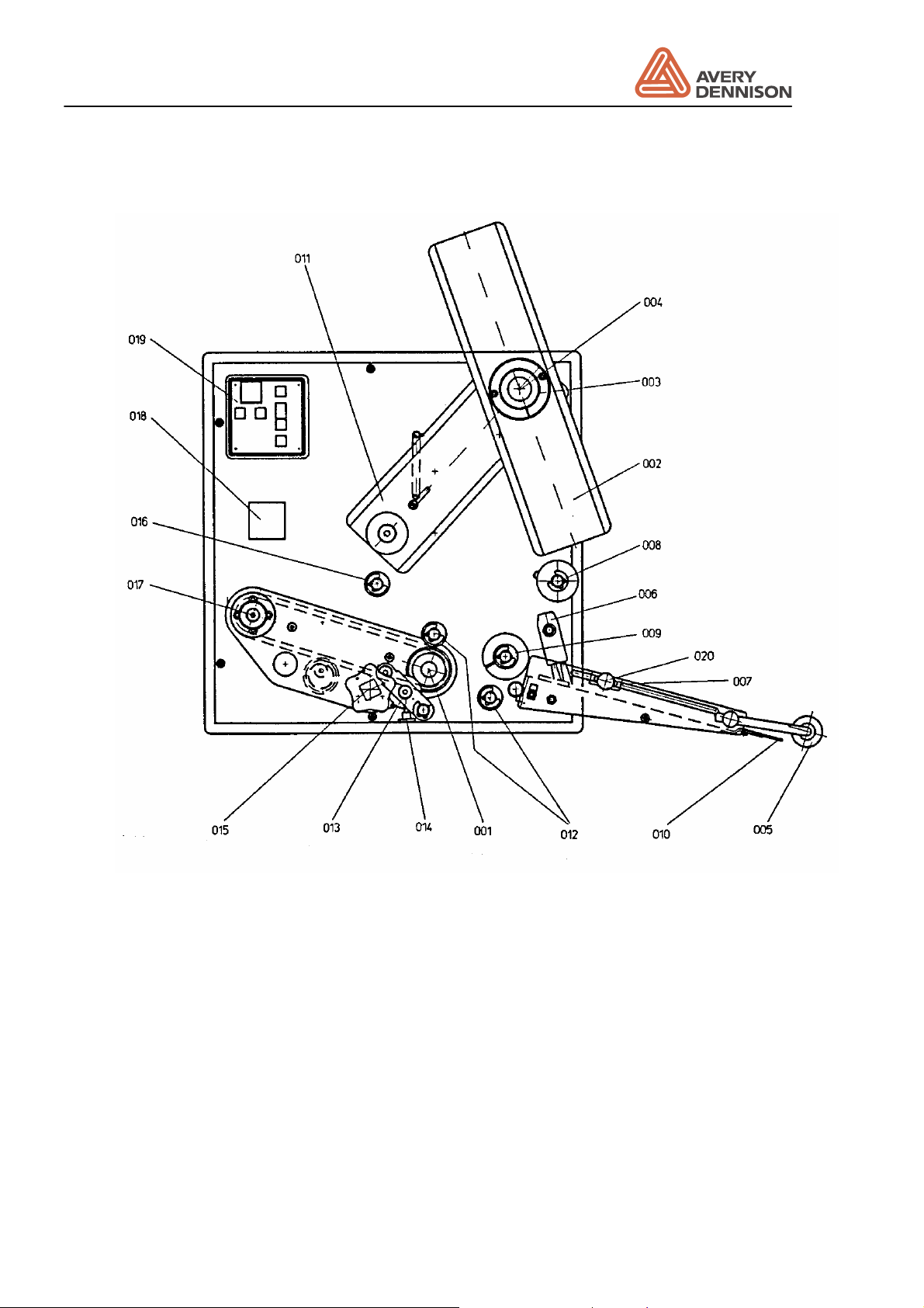
machine are shown below.
The label material is unwound from roller (003). The maximum diameter of the label roll is 300
mm. The maximum width is 100 mm. The material roll is guided by two removable plate’s (002).
The guide plate in front has to be pressed against the label roll. Behind the cap (004) of unwind
mandrel (003) an adjustment screw for the brake is located. The unwind brake avoids after run
of the label roll when the label drive stops.
Note: For labels longer than 100 mm and in "side labelling applications" it is
recommended to use the optional available kit dancer arm controlled unwind brake
.
This device avoids uncontrolled after run of label material. The brake should not be
fixed too tight, otherwise the motor may stall or the material web gets broken.
The dancer arm (011) keeps the material tight and the acceleration forces low. The deviator
roller (008) makes sure that the material is guided correctly. The material is guided to the
dispensing edge via the deviator roller (009).
The brush (006) keeps the material tight without disturbing the movement. At the dispensing
edge (010) the label sensor (007) is mounted. The label sensor detects the gaps between
labels. The label sensor comprises of a light source and a light receiver. The sensitivity can be
adjusted by the operators panel.
Operators Manual
ALS 230
Release 11/05 Page 12 Description
Figure 1 Dispensing mechanics
At the dispensing edge (010) the label is separated from the backing paper. By means of a soft
(005) roller the label is applied on to the product.
Roller (012) makes sure that the material is always guided properly around the dispensing
edge. Drive roller (001) keeps the transport speed of the material constant.
Deviator rollers (012) guide the backing material around the drive roller (001). The pressure
mechanics (013) press the backing paper against the drive roller (001).
With the handle (015) you may open and close the pressure mechanics (013) . When inserting
the material the pressure roller has to be opened.
Operators Manual
ALS 230
Release 11/05 Page 13 Description
Dispensing is only possible when the handle (015) is in the closed position. Via the deviator
roller (016) the backing paper is guided to the rewind mandrel (017). The cone between the 4
pins can be pulled out to allow the reward backing paper to be removed.
Except for the drive roller (001) and the material brush (006) the labeller has no wearing parts.
The operator panel (019) is described in the next chapter.
A threading diagram is affixed to the front of the machine, which shows how the label material
should be threaded through the machine.
Screw (014) secures the position of the pressure roller (013) in a lateral direction. In order to
achieve a reliable run of the label web position, adjust the roller to the centre of the label web.
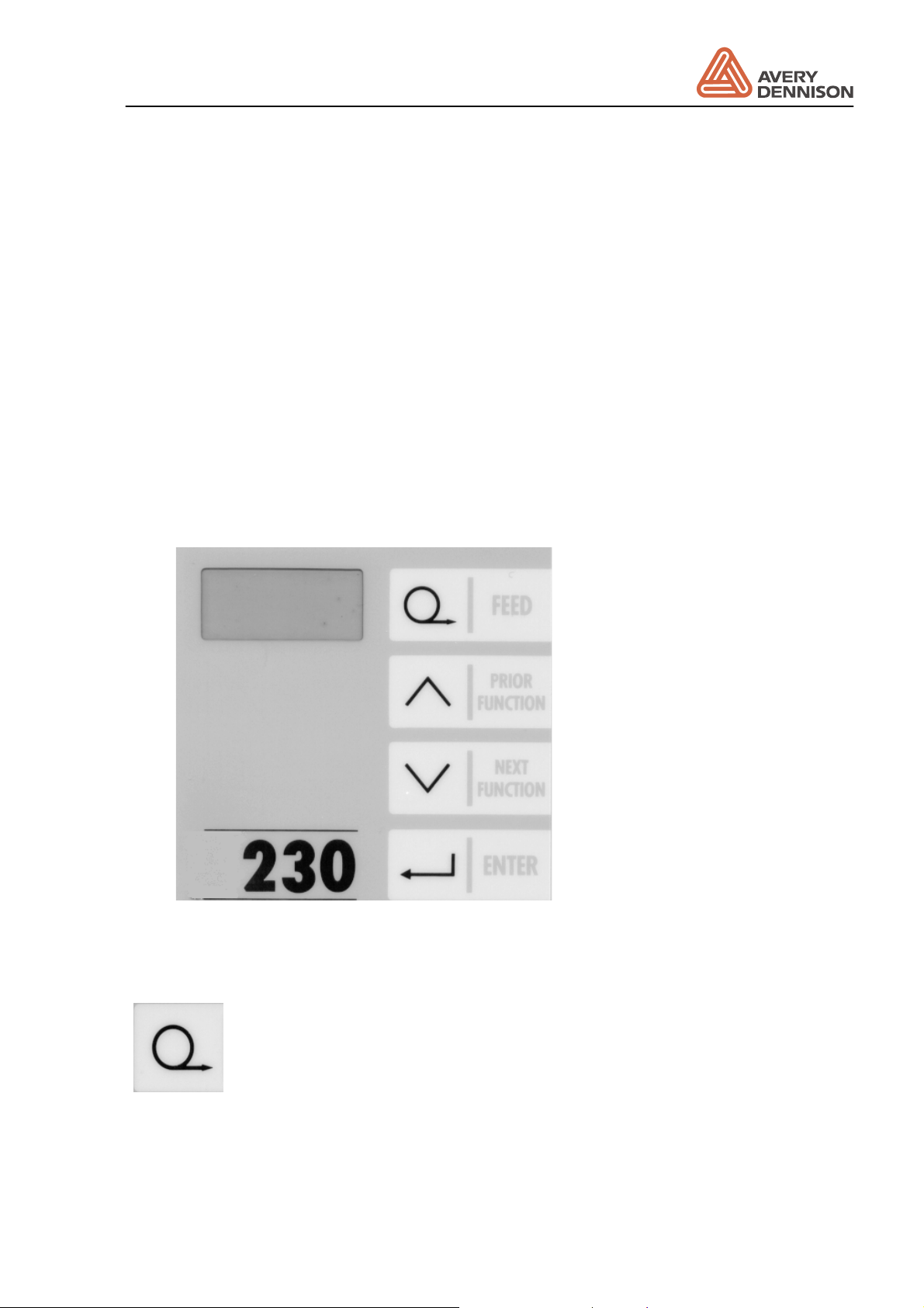
2.2 Operator panel
The operator panel (Figure 2) of the 230 is shown below, it has a 4 digit LED display and 4
membrane keys.
Figure 2 Operator panel
The 4 membrane keys have following functions:
FEED: By pressing this key one label will be dispensed. When the machine
displays INIT pressing this key will start initialisation of the machine. An
initialisation has to be made each time a new material is used. If the FEED key is
pressed and held as the machine is turned on then the machine carries out an
automatic initialisation of the label parameters "CONT" and "LPIT".

Operators Manual
ALS 230
Release 11/05 Page 14 Description
PRIOR: This key moves up the menu (prior function) or increases the value of a
parameter. If the up arrow key is pressed and held as the machine is turned on
the product menu is selected.
NEXT: This key moves down the menu (next function) or decreases the value of
a parameter. If the down arrow key is pressed and held as the machine is turned
on the standard menu is selected.
ENTER: This key is used to enter or exit a menu point or to cancel a warning or
error message.
When the keys have different meanings, it will be explained in the relevant menu description.
Operators Manual
ALS 230
Release 11/05 Page 15 Description
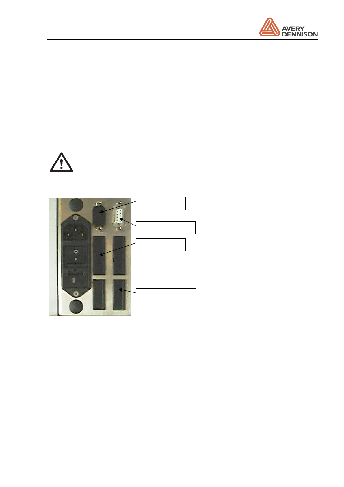
2.3 Plug board
The plug board is shown in Figure 3. Beside the mains switch and the mains cable socket there
are some more holes for optional functions. Standard execution in this machine is one I/O plug
prepared for the product sensor. The connection of the other plugs is described in chapter
Connections.
If you use the optional connections, it is strongly recommended to do this by means of the
optional available SUB-D connectors. This ensures best EMI stability of the machine.
CAUTION! - The fuse holder setting you have to select according to your local
main voltage (100, 120, 200 or 230 V). You carry this out by taking off the fuse
holder and position the fuse holder insert accordingly.
Figure 3 Plug board
2.4 Electronic
As standard the complete electronic is integrated in the machine. For special requirements
(water protection e.g.) a machine version the electronic is housed in a separate cabinet is
available.
Product sensor
APSF-Sensor
Applicator
PLC control

Operators Manual
ALS 230
Release 11/05 Page 16 Description

Operators Manual
ALS 230
Release 11/05 Page 17 Preparing the machine
3. Preparing the machine
In this chapter you will learn how to install and adjust the labeller. After this step has been
completed you will be ready to learn how the labeller's parameters can be adjusted to suit your
particular production requirements.
1.1 Installation
1.1.1 Unpacking of the unit
• For removing the unit off the box, don’t hold the machine on the dispensing edge to prevent
disadjustment off the machine.
• For mounting the machine, a complete system of holding tools is available. Ask your
representative.
• Take care that the machine is safe and stable mounted.
• There are rotating parts on the machine. Do the necessary actions to prevent that anybody
can be caught from these parts.
1.1.2 Connection of the machine
Before connecting the machine to the mains, check the correct setting of the line voltage. For
the connection of sensor, applicators e.g. see the chapter connections. Fix all cables to prevent
accidents and damaging of cables. Have also a look to the EMI chapter for proper machine
operation.
For checking of correct operation of sensors, applicators use the check functions SCHK, I_CH
and O_CH.
1.1.3 General setting
Normally the setting is done, but before operation check and note the general dispenser
configuration: dispenser direction, machine type, applicator mode, and APSF function.

Operators Manual
ALS 230
Release 11/05 Page 18 Preparing the machine
1.2 Prepare dispensing
1.2.1 Insert material
Insert your label material in the machine to follow the instructions in the chapter Operation /
Threading.
1.2.2 Define label data
For correct dispenser operation, you have to tell the machine the length of the label and adjust
the label sensor. Normally this is done automatically. For this follow the instructions in chapter
Operation / Initialise material.
There are some reasons the automatic initialisation is not possible:
1. Using another then the standard optical label sensor
2. Label material with a low contrast ratio between label and backing paper
3. Labels with holes inside the label
In this case, you have to set one or both of the parameter manually.
Activate the extended standard menu to do the settings by:
y Pressing both keys NEXT and PRIOR simultaneously
Display: CODE
y Password CODE entering:
1 time pressing the key PRIOR FUNCTION
2 times pressing the key NEXT FUNCTION
3 times pressing the key ENTER
Display: LPIT
y Setting the label length
Enter the LPIT function by pressing ENTER. Measure the distance from one label edge to
the edge of the next label. Enter the value in mm by using the function keys. Press ENTER
to leave the function. See also the information below.
y Change the setting of the label sensor
If another label sensor then the Wenglor type will be used, call the CONT function and set
the value to any manual value (e.g. M006.).
If the contrast ratio is low, follow the instructions to adjust manually contrast.
y To store the setting permanent leaves the menu with the QUIT function. If you power off the
machine without quit all modification are lost.
y By pressing the key FEED one label can be dispensed if you are in the parameter selection.
Operators Manual
ALS 230
Release 11/05 Page 19 Preparing the machine
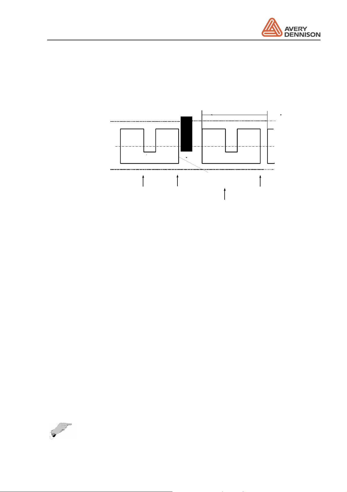
Setting LPIT manually
To initialise labels with cut outs such as the one shown below - the "LPIT" parameter should be
used to enter the label pitch of the label web.
Sensor signals
Label sensor
LPIT
real leading
edge of label
Figure 4 Definition of LPIT
All other label edges seen by the label sensor will be ignored until the distance adjusted in the
"LPIT" parameter has been fed through the label sensor.
Manual adjustment of the CONT parameter
y Remove a label from the backing paper and slide it inside the sensor.
y Reduce the value with the PRIOR key until the LED switched on.
y Press the key NEXT until the LED switched off. If there are marks an the backing paper do
the measurement on this position.
y Note the value GAP xxx
y Slide the backing paper including label inside the sensor. Use the lightest position on the
label for the adjustment.
y Increase with the NEXT key the value until LED lights again. Note the second value GAP
yyy
y Calculate the contrast value by the formula (xxx + yyy) / 2 and set it.
y Manual adjustment is completed.
With a difference of less than 20 an operation with this kind of sensor is not possible
(sometimes two or more labels are dispensed).
3.1.1 Capacitive label sensor
For transparent labels the standard photo label sensor doesn’t work. In this case, use a
mechanic or a capacitive label sensor.
Note: For correct automatic initialisation, the CONT parameter has to be set to a
manual value, if you using not the standard photo sensor.
Operators Manual
ALS 230
Release 11/05 Page 20 Preparing the machine
A mechanical sensor is limited in the speed. The bounce at the label edges produces wrong
signals.
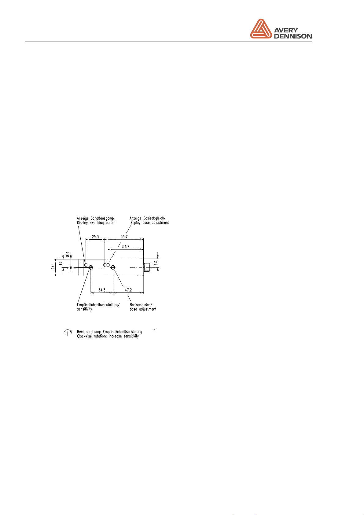
There is optional a capacitive label sensor available (Leuze GK14/24L).
Adjustment of the sensor is carried out as follows (Figure 5):
1. Set sensitivity to maximum by turning the Potentiometer clockwise. Then rotate ½ turn
anticlockwise.
2. Remove label material out of sensor.
3. Perform base adjustment, that both LED “base adjustment” have the same brightness.
4. Put label with backing paper inside the sensor. Doing this, the LED “switch output” and the
left LED “base adjustment” are switched off. With backing paper only in the sensor both
LED are switched on. If the LED are lightning with label inside the sensor, increase
sensitivity in ¼ turn steps by rotating the sensitivity clockwise.
5. Check the adjustment over the complete length of label.
Carry out the above adjustment after mounting, cleaning or increasing sensitivity.
Figure 5 Capacitive sensor
3.2 Label guide
On some of the axles, they’re guiding clamps. Adjust the clamps near the machine so all have
the same distance to the front plate (31.5mm). The outer clamps should be mounted that the
guide but not bend the label material.
The front of the V-dispensing edge has a rot, which can be adjusted for straighten the material
guiding. Spend several labels by pressing the dispenser FEED key. If the material guiding is
running out of the guiding way, adjust the rot by loosing two screws at the dispensing edge.

Operators Manual
ALS 230
Release 11/05 Page 21 Preparing the machine
With a L-dispensing the adjustment is done by move the tail sheaves behind the dispensing
edge.
3.3 Adjust dispense function
For an operation without any trouble and high label accuracy, tree adjustments are required:
• Label position on the dispensing edge: stop position
• Dispense speed
• Label position on the product
The adjustment should be done in the same order, because parameter like the stop position
depends on the setting of the stop position and the dispensing speed.
3.3.1 Stop position
The first step is to adjust the stop position. This is the basic adjustment of the dispense
process. Also in case of problems with the machine check if the stop position is okay.
Figure 6 Stop position
The stop position should be adjusted so that the label stops at the dispensing edge up to 3 mm
behind.
For a correct operation of the automatic label compensation, they will compensate a missing
label on the web, first the distance between label sensor and dispensing edge has to be
defined. Do this by calling the DIST function in the configuration menu. Check the setting by
removing a label before the label sensor from the web. Give a start signal to the machine by
triggering the start sensor (not the FEED key) and see if the compensation is done on the right
position. Do the fine adjustment with the STOD function.
3.3.2 Fixed dispensing speed
The second step is to adjust the dispense speed. If an APSF sensor is used see 3.3.3.
If an applicator is used, then the dispense speed has no influence to the dispense process.
Continue with 3.3.4.
Set POS to the distance between start sensor and dispensing edge. If installed remove the
roller to press the label onto the product. Now try to dispenser one product. If the label has
wrinkles reduce the speed VELO. If the product peels out the label, so the stop position of the
next label is different to the last position increase the speed. Normally your dispense speed
should be a little bit higher than your product speed.

Operators Manual
ALS 230
Release 11/05 Page 22 Preparing the machine
3.3.3 Automatic dispensing speed (APSF)
With a connected rotary encoder, the dispensing speed follows the measured product speed.
To adjust the speed use the EGRA function located in the extended standard menu. The
measured speed will be displayed in the VELO function. Do the adjustment in the same way
described for fixed speed.
3.3.4 Label position on the product
At least adjust the position of the label on the product with the POS function or with the STAD
function, if an applicator is in use.
3.3.5 Product data bank
Save your setting in one of the product data banks. If different products and / or labels are in
use up to nine different combinations could be stored. Define and store the different product
data. The select the product data bank mode by holding the PRIOR key during power on.
Switch back to normal mode by holding the NEXT key.

Operators Manual
ALS 230
Release 11/05 Page 23 Operation
4. Operation
This chapter describes the operation of the machine.
4.1 Safety recommendation
CAUTION!
y Before connections to the mains check the correct voltage selection.
y Use only original spare parts for service.
y Open of the cover is only allowed authorised personal.
y Handling of the machine is permitted only trained personal.
y Be careful on operation, fingers, hair, clothes, jewellery, etc. may be caught
by and get into rotating axles.
Operators Manual
ALS 230
Release 11/05 Page 24 Operation
4.2 Inserting label material
Attention:
• Before threading the new material, the waste paper should be removed.
CAUTION! - Isertion/exchange of material should be carried out only by
especially instructed personal.
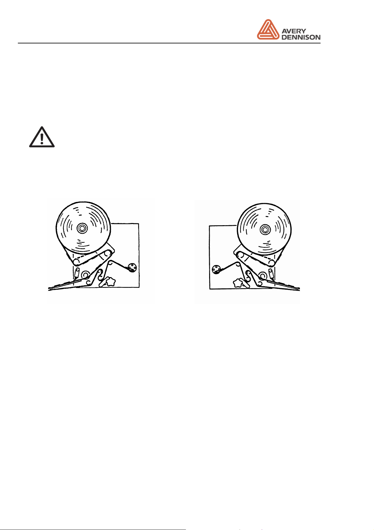
Threading of the label material is shown down below on the threading diagrams for the
right-hand and the left-hand version.
left hand version right hand version
Figure 7 Threading diagram
y Hang document material in reel holder in a way to ensure unwinding that label in the printer
section is on the top. Put outer guide disk onto mandrel. The two guide plates keep the label
roll reliably in position on the unwind mandrel.
y Guide material around the dancer arm.
y Labels behind the dispensing edge should be removed. The material brush has to be
positioned in a way, that the material is kept tight. From time to time, it is recommended to
reverse the mounting of the brush while you are loading a new label roll.
y Adjust the pressure roller before the rewind, so that it is right in the middle of the material.
Close the pressure roll and turn the roll 2 or 3 times, so that the material is threaded. Check
that the material is guided straight.
y Check correct position of the label sensor.
Loading...