


 Loading...
OPERATING MANUAL
Label Dispenser
ALS
350
450
Article number: A6432, Release 06.2005

|
CONTENTS |
ALS |
|
|
350 |
|
|
450 |
|
|
|
1 Please observe the following
1.1 General information . . . . . . . . . . . . . . 6
1.1.1 Validity and applicability of this manual . . . . . 6 Contents . . . . . . . . . . . . . . . . . . . . . . . . . . . . . 6 Technical State . . . . . . . . . . . . . . . . . . . . . . . . 6 Copyright notice . . . . . . . . . . . . . . . . . . . . . . . 6 Manufacturer. . . . . . . . . . . . . . . . . . . . . . . . . . 6
1.1.2 Conventions and information . . . . . . . . . . . . . 7 Explanation of symbols . . . . . . . . . . . . . . . . . . 7 Warnings concerning dangers and risks. . . . . 7 Illustrations . . . . . . . . . . . . . . . . . . . . . . . . . . . 7 Supplemental information . . . . . . . . . . . . . . . . 7 Directional information . . . . . . . . . . . . . . . . . . 8 ALS 350 and ALS 450 . . . . . . . . . . . . . . . . . . 8
1.2 Safety instructions . . . . . . . . . . . . . . . 9
1.2.1 Information and qualifications . . . . . . . . . . . . . 9 Pay attention to the information . . . . . . . . . . . 9 Information must be made available . . . . . . . . 9 Ensure necessary qualifications . . . . . . . . . . . 9
1.2.2 Machine operating safety . . . . . . . . . . . . . . . 10 Appropriate use. . . . . . . . . . . . . . . . . . . . . . . 10 Protect against injuries that can result from electrical current . . . . . . . . . . . . . . . . . . . . . . . . . 10 Protect against injuries that can result from mechanical actions . . . . . . . . . . . . . . . . . . . . . . 10 Protection against chemical injuries . . . . . . . 10
1.2.3 Before every production start . . . . . . . . . . . . 11 Operator's obligation and service personal to exercise care. . . . . . . . . . . . . . . . . . . . . . . . . 11 Operating personnels' obligation to exercise care . . . . . . . . . . . . . . . . . . . . . . . . . . . . . . . . 11
2 Equipment description
2.1 Overview of the ALS 350. . . . . . . . . 12
2.1.1 Structural elements . . . . . . . . . . . . . . . . . . . . 12 2.1.2 Principle of operation . . . . . . . . . . . . . . . . . . 14
2.1.3 Technical data. . . . . . . . . . . . . . . . . . . . . . . . 16 Characteristic values. . . . . . . . . . . . . . . . . . . 16 Labels . . . . . . . . . . . . . . . . . . . . . . . . . . . . . . 16 Ambient conditions . . . . . . . . . . . . . . . . . . . . 16 Dimensions . . . . . . . . . . . . . . . . . . . . . . . . . . 16 Casing. . . . . . . . . . . . . . . . . . . . . . . . . . . . . . 16 Electrical system . . . . . . . . . . . . . . . . . . . . . . 16 Control system . . . . . . . . . . . . . . . . . . . . . . . 16 Emissions . . . . . . . . . . . . . . . . . . . . . . . . . . . 16
2.1.4 Design versions . . . . . . . . . . . . . . . . . . . . . . 17 Right-hand version . . . . . . . . . . . . . . . . . . . . 17 Left-hand version . . . . . . . . . . . . . . . . . . . . . 17
2.2 Overview of the ALS 450 . . . . . . . . . 18
2.2.1 Structural elements . . . . . . . . . . . . . . . . . . . 18 2.2.2 Principle of operation . . . . . . . . . . . . . . . . . . 20
2.2.3 Technical data . . . . . . . . . . . . . . . . . . . . . . . 22 Characteristic values . . . . . . . . . . . . . . . . . . 22 Labels . . . . . . . . . . . . . . . . . . . . . . . . . . . . . 22 Ambient conditions. . . . . . . . . . . . . . . . . . . . 22 Dimensions . . . . . . . . . . . . . . . . . . . . . . . . . 22 Casing . . . . . . . . . . . . . . . . . . . . . . . . . . . . . 22 Electrical system . . . . . . . . . . . . . . . . . . . . . 22 Control system . . . . . . . . . . . . . . . . . . . . . . . 22 Emissions. . . . . . . . . . . . . . . . . . . . . . . . . . . 22
2.2.4 Design versions . . . . . . . . . . . . . . . . . . . . . . 23 Right-hand version . . . . . . . . . . . . . . . . . . . . 23 Left-hand version . . . . . . . . . . . . . . . . . . . . . 23
2.3 Options . . . . . . . . . . . . . . . . . . . . . . . 24
Serial interface . . . . . . . . . . . . . . . . . . . . . . . 24 Roll diameter control . . . . . . . . . . . . . . . . . . 24 Adjustable dispensing edge . . . . . . . . . . . . . 24 Spring-loaded dispensing edge . . . . . . . . . . 24 Pneumatic dispensing edge. . . . . . . . . . . . . 24 Printer. . . . . . . . . . . . . . . . . . . . . . . . . . . . . . 24 Applicator . . . . . . . . . . . . . . . . . . . . . . . . . . . 24 Water-resistant electronic control unit . . . . . 24
2.4 Operator controls . . . . . . . . . . . . . . . 25
2.4.1 Operator panel . . . . . . . . . . . . . . . . . . . . . . . 25 LED indicator . . . . . . . . . . . . . . . . . . . . . . . . 25 Keys . . . . . . . . . . . . . . . . . . . . . . . . . . . . . . . 25
2.4.2 Main switch . . . . . . . . . . . . . . . . . . . . . . . . . 26
2.5 Control system . . . . . . . . . . . . . . . . . 27
2.5.1 Brief description . . . . . . . . . . . . . . . . . . . . . . 27
2.5.2Menus for operators and calibration technicians 28
2.5.3 Monitoring functions. . . . . . . . . . . . . . . . . . . 29 Dispensing a label to each product . . . . . . . 29 Label supply. . . . . . . . . . . . . . . . . . . . . . . . . 29 If errors occur. . . . . . . . . . . . . . . . . . . . . . . . 29
3 Prior to operating
3.1Insert the labelling material – ALS 350.
3

CONTENTS
30
3.1.1 Prerequisites . . . . . . . . . . . . . . . . . . . . . . . . . 30
3.1.2 Insert the label roller . . . . . . . . . . . . . . . . . . . 30 Remove the old backing material . . . . . . . . . 30 Remove adhesive residues. . . . . . . . . . . . . . 30 Insert new label roll . . . . . . . . . . . . . . . . . . . . 31
3.1.3 Threading the label ribbon . . . . . . . . . . . . . . 32 Overview of the threading path diagram . . . . 32 Thread the label ribbon at the unwind unit . . 33 Guide the label ribbon around the dispensing edge . . . . . . . . . . . . . . . . . . . . . . . . . . . . . . . 34 Thread the label ribbon at the rewind unit. . . 35
3.2Insert the labelling material – ALS 450
36
3.2.1 Prerequisites . . . . . . . . . . . . . . . . . . . . . . . . . 36
3.2.2 Insert the label roller . . . . . . . . . . . . . . . . . . . 36 Remove the old backing material . . . . . . . . . 36 Remove adhesive residues. . . . . . . . . . . . . . 36 Insert new label roll . . . . . . . . . . . . . . . . . . . . 37
3.2.3 Threading the label ribbon . . . . . . . . . . . . . . 38 Overview of the threading path diagram . . . . 38 Thread the label ribbon at the unwind unit . . 39 Guide the label ribbon around the dispensing edge . . . . . . . . . . . . . . . . . . . . . . . . . . . . . . . 40 Thread the label ribbon at the rewind unit. . . 41
3.3 Mechanical settings . . . . . . . . . . . . . 42
3.3.1 Setting the ribbon guides . . . . . . . . . . . . . . . 42 Operator panel support . . . . . . . . . . . . . . . . . 42 Setting the ribbon guides on the dispenser head 42
Deflection roller on the rewind unit . . . . . . . . 42
3.3.2Adjust pressure roller at the dispensing edge43
3.3.3Adjust the pressure roller and the braking brush 44
Pressure roller. . . . . . . . . . . . . . . . . . . . . . . . 44 Braking brush . . . . . . . . . . . . . . . . . . . . . . . . 44
3.3.4 Adjust (optional) the position of the dispensing edge . . . . . . . . . . . . . . . . . . . . . . . . . . . . . . . 45 Adjusting vertically . . . . . . . . . . . . . . . . . . . . 45
ALS 350 450
Manually initialise the material . . . . . . . . . . . 47
4.1.2 Labelling. . . . . . . . . . . . . . . . . . . . . . . . . . . . 48 Prerequisites . . . . . . . . . . . . . . . . . . . . . . . . 48 Start dispensing labels. . . . . . . . . . . . . . . . . 49 Unwind unit . . . . . . . . . . . . . . . . . . . . . . . . . 50 Rewind unit . . . . . . . . . . . . . . . . . . . . . . . . . 50
4.1.3 Stop/end the label dispensing . . . . . . . . . . . 50
4.1.4 Tandem operation . . . . . . . . . . . . . . . . . . . . 51 Principle of operation . . . . . . . . . . . . . . . . . . 51 Prerequisites . . . . . . . . . . . . . . . . . . . . . . . . 52 Start dispensing labels. . . . . . . . . . . . . . . . . 52 Reloading label material. . . . . . . . . . . . . . . . 53 Switching off. . . . . . . . . . . . . . . . . . . . . . . . . 54
4.2 Setting and monitoring . . . . . . . . . . . 55
4.2.1 Settings in the standardmenu . . . . . . . . . . . 55 Overview . . . . . . . . . . . . . . . . . . . . . . . . . . . 55 Calling up menu . . . . . . . . . . . . . . . . . . . . . . 55 Call up function . . . . . . . . . . . . . . . . . . . . . . 55
4.2.2 Label stop position . . . . . . . . . . . . . . (STOD)56
4.2.3 Dispensing speed. . . . . . . . . . . . . . . (VELO)57 Automatic dispensing speed (optional) . . . . 57
4.2.4 Label position on the product
(POS) . . . . . . . . . . . . . . . . . . . . . . . . . . . . . . 58 4.2.5 Automatic material initialisation . . . . . . (INIT)59
4.2.6 If errors occur. . . . . . . . . . . . . . . . . . . . . . . . 60 Warning messages . . . . . . . . . . . . . . . . . . . 60 Error messages . . . . . . . . . . . . . . . . . . . . . . 60
4.3 Product databanks . . . . . . . . . . . . . . 61
4.3.1 Functions . . . . . . . . . . . . . . . . . . . . . . . . . . . 61
4.3.2 Loading product data banks. . . . . . . . . . . . . 61 Please observe: . . . . . . . . . . . . . . . . . . . . . . 61 Activating product databanks at switch-on. . 62 Activating product databanks after switch-on .
62
4.3.3 Create/save product databank . . . . . . . . . . 63 Prerequisites . . . . . . . . . . . . . . . . . . . . . . . . 63 Saving the product databank . . . . . . . . . . . . 63 Documenting product databanks . . . . . . . . . 63
4.3.4 Delete the product databank . . . . . . . . . . . . 64
4 |
Operation |
4.4 Settings in the extended menu. . . . . |
65 |
4.1 Activation and shut-down. . . . . . . . . 46
4.1.1 Starting the machine . . . . . . . . . . . . . . . . . . . 46 Automatic material initialisation. . . . . . . . . . . 46
4.4.1 Overview . . . . . . . . . . . . . . . . . . . . . . . . . . . 65
4.4.2 Activating an extended menu. . . . . . . . . . . . 67 Please observe: . . . . . . . . . . . . . . . . . . . . . . 67 Calling up menu . . . . . . . . . . . . . . . . . . . . . . 67
4

|
CONTENTS |
ALS |
|
|
350 |
|
|
450 |
|
|
|
Call up function . . . . . . . . . . . . . . . . . . . . . . . 67 Exit the extended menu . . . . . . . . . . . . . . . . 67
4.4.3 Position of second label
(POS2) . . . . . . . . . . . . . . . . . . . . . . . . . . . . . 68 4.4.4 Position of third label. . . . . . . . . . . . . (POS3)68 4.4.5 Speed ratio . . . . . . . . . . . . . . . . . . . . (VERT)69
4.4.6 Adjust the label stop sensor (CONT) . . . . . . 70 Technology . . . . . . . . . . . . . . . . . . . . . . . . . . 70 Automatically adjusting the photoelectric sensor 70
Manually adjusting the sensor . . . . . . . . . . . 71
4.4.7 Label distance. . . . . . . . . . . . . . . . . . . (LPIT)72 Set distance . . . . . . . . . . . . . . . . . . . . . . . . . 72 Check setting . . . . . . . . . . . . . . . . . . . . . . . . 72
4.4.8Distance from the label stop sensor to the dispensing edge
(E–SS) . . . . . . . . . . . . . . . . . . . . . . . . . . . . . 73 Set distance . . . . . . . . . . . . . . . . . . . . . . . . . 73 Check setting . . . . . . . . . . . . . . . . . . . . . . . . 74
4.4.9 Product length . . . . . . . . . . . . . . . . . |
(PRDL)75 |
4.4.10 Polarity of the product sensor |
|
(P_S_). . . . . . . . . . . . . . . . . . . . . . . . |
. . . . . . 76 |
4.4.11 Polarity of the label stop sensor . . . . |
(S_S_)76 |
4.4.12 Number of unlabelled products |
|
(MLAB) . . . . . . . . . . . . . . . . . . . . . . . |
. . . . . . 77 |
4.4.13 Electronic transmission ratio of the RPM transmitter (EGRA) . . . . . . . . . . . . . . . . . . . . . . . . 77
4.4.14 Advance print start . . . . . . . . . . . . . . . (PDT)78 4.4.15 Printer dwell time . . . . . . . . . . . . . . .(PDWT)78 4.4.16 Tandem operation. . . . . . . . . . . . . . .(TMOD)79 4.4.17 Applicator type . . . . . . . . . . . . . . . . . (APPL)79 4.4.18 EP cylinder dwell time. . . . . . . . . . . . (APT1)79 4.4.19 Blowing time . . . . . . . . . . . . . . . . . . . (APT2)79
4.4.20 Delay time . . . . . . . . . . . . . . . . . . . . |
(APT3)79 |
4.4.21 Fine tuning of the dwell time |
(APT4)79 |
. . . . . . . . . . . . . . . . . . . . . . . . . . . . . |
|
4.4.22 Delete a product data bank |
(LOAD)79 |
. . . . . . . . . . . . . . . . . . . . . . . . . . . . . |
|
4.4.23 Create/save product data bank |
(SAVE)79 |
. . . . . . . . . . . . . . . . . . . . . . . . . . . . . |
|
4.4.24 Delete a product data bank |
(DEL)79 |
. . . . . . . . . . . . . . . . . . . . . . . . . . . . . |
4.5Automatic dispensing speed (APSF) 80
4.5.1 Principle of operation . . . . . . . . . . . . . . . . . . 80
4.5.2 Electronic transmission ratio of the RPM transmitter . . . . . . . . . . . . . . . . . . . . . . . . (EGRA)81 Setting the compensation factor. . . . . . . . . . 81 Test the setting. . . . . . . . . . . . . . . . . . . . . . . 81
4.6 Applicator (optional) . . . . . . . . . . . . . 82
4.6.1 Principle of operation . . . . . . . . . . . . . . . . . . 82
4.6.2 Functions in the extended menu . . . . . . . . . 83 Please observe the following: . . . . . . . . . . . 83 Calling up the extended menu. . . . . . . . . . . 83 Applicator type . . . . . . . . . . . . . . . . . .(APPL)83 EP cylinder dwell time . . . . . . . . . . . . (APT1)84 Blowing time. . . . . . . . . . . . . . . . . . . . (APT2)84 Delay time . . . . . . . . . . . . . . . . . . . . . (APT3)84 Fine tuning of the dwell time . . . . . . . (APT4)85
5 After operation
5.1 Care and cleaning . . . . . . . . . . . . . . 86
5.1.1 Cleaning agents . . . . . . . . . . . . . . . . . . . . . . 86
5.1.2 Regular maintenance. . . . . . . . . . . . . . . . . . 86 Remove paper waste . . . . . . . . . . . . . . . . . . 87 Braking brush. . . . . . . . . . . . . . . . . . . . . . . . 87 Capacitive sensor at the dispenser head. . . 88
6 Operational malfunctions
6.1 Warning messages. . . . . . . . . . . . . . 89
6.1.1 Please observe: . . . . . . . . . . . . . . . . . . . . . . 89 6.1.2 If a problem occurs. . . . . . . . . . . . . . . . . . . . 89 6.1.3 Warning messages . . . . . . . . . . . . . . . . . . . 89
6.2 Error messages . . . . . . . . . . . . . . . . 91
6.2.1 If a malfunction occurs . . . . . . . . . . . . . . . . . 91 6.2.2 Error codes. . . . . . . . . . . . . . . . . . . . . . . . . . 91
7 Appendix
7.1 Factory settings . . . . . . . . . . . . . . . . 95
7.2 Product databanks . . . . . . . . . . . . . . 97 7.3 EC Declaration of Conformity. . . . . . 99
5

|
1 |
PLEASE OBSERVE THE FOLLOWING |
ALS |
|
1.1 |
GENERAL INFORMATION |
350 |
|
450 |
||
|
|
|
|
|
|
|
|
1.1.1 Validity and applicability of this manual
Contents
The present manual refers exclusively to the ALS 350 and ALS 450 labeller machines. The manual is to be referred to for correct operation and adjustment of the machine.
The prerequisites for operation and adjustment are proper installation and configuration of the machine.
For technical questions which are not addressed in this operating manual:
Observe the instructions contained in the labeller service guide
or
Request assistance from a service technician at our sales partner.
–The customer service at our sales partner is at your disposal and particularly helpful with configuration settings and remedying malfunctions.
Copyright notice
All rights to this operating manual are assigned to Avery Dennison. Transmission, reprinting or any other means of reproduction of this manual, whether whole or in part, are not allowed without prior written permission. Third parties, in particular competitors, are not to be allowed access to information derived from this manual.
Printed in Germany
Manufacturer
Avery Dennison Deutschland GmbH Ohmstraße 3
D–85386 Eching Phone: +49-8165-925-0 Fax: +49-8165-3143
http://www.machines.averydennison.com
Technical State
Technical state as of: 06/2005
Software version: 6.1
Avery Dennison reserves the right to:
–implement modifications of structural parts, components and software as well as to use equivalent components that keep pace with the current state of technology in lieu of the specified components.
–change information contained in this manual.
An obligation to extend these modifications to previously delivered machines is excluded.
6

|
1 |
PLEASE OBSERVE THE FOLLOWING |
ALS |
|
1.1 |
GENERAL INFORMATION |
350 |
|
450 |
||
|
|
|
|
|
|
|
|
1.1.2 Conventions and information
Explanation of symbols
In order to facilitate legibility and an overview, the various types of information used herein are categorised and identified with certain symbols.
Sentences that are introduced by an arrow contain procedural instructions.
Carry out procedural instructions one after the other in the prescribed order.
The following information is introduced with a dash:
–List items
–Descriptions of conditions
–Description of previous work steps
–Prerequisites for implementing actions described in the following passage
Warnings concerning dangers and risks
Important text passages which must absolutely be followed are particularly marked for special attention:
DANGER!
A danger notice indicates an imminent hazardous situation which, if not avoided, could result in death or serious injury of the personnel!
The notice contains instructions on how to avoid or prevent the danger(s).
The instructions must be followed.
WARNING!
A warning notice indicates risks which could result in death or serious injury of the personnel! The notice contains safety instructions on how to safeguard possibly affected personnel.
The instructions must be followed.
CAUTION!
A caution notice indicates risks which, if unheeded, could lead to material damage or bodily injury (minor injuries). The notice contains instructions on how to prevent damage or injury.
The instructions must be followed.
Illustrations
When required, text passages are accompanied by illustrations. The reference to an illustration is indicated by typesetting the [illustration number] in square brackets. Capital letters following an illustration number, e.g. [12A], refer to the corresponding position indicated in the illustration.
In general, the right-hand version of labeller ALS 350 is depicted in the illustrations. The left-hand version or the ALS 450 are only depicted if differentiation is necessary.
Supplemental information
The "Experts" symbol earmarks activities that only to be performed by knowledgeable and trained personnel.
The information symbol indicates notices and recommendations as well as additional helpful information.
Operating materials:
–Operating materials, e.g. lubricants or cleaning agents
7
|
1 |
PLEASE OBSERVE THE FOLLOWING |
ALS |
|
1.1 |
GENERAL INFORMATION |
350 |
|
450 |
||
|
|
|
|
|
|
|
|
Directional information
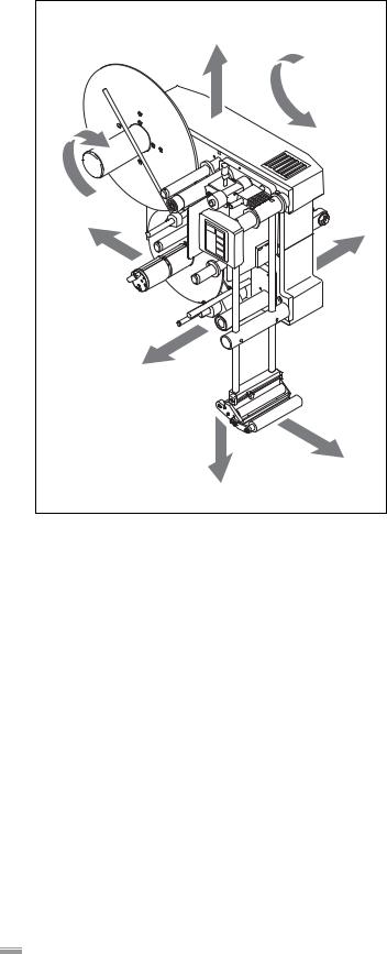
Unless otherwise indicated, the directional information mentioned in the text refers to the construction of the right-hand version of Top Labeller. See Figure [1] for the explanation of directional information.
ALS 350 and ALS 450
The operation of the two labellers described in this operating manual is very similar. In general, the righthand version of labeller ALS 350 is described. The lefthand version or the ALS 450 are only discussed if the descriptions deviate significantly.
In the header of each page, it is annotated whether the respective page applies to the ALS 350 and ALS 450 or to only one of the two types.
|
C |
|
H |
G |
|
E |
B |
|
A |
|
F |
|
D |
[1]Definition of directional information A Front
B Rear
C Upward
D Downward E Left
F Right
G Clockwise
H Counter-clockwise
8

|
1 |
PLEASE OBSERVE THE FOLLOWING |
ALS |
|
1.2 |
SAFETY INSTRUCTIONS |
350 |
|
450 |
||
|
|
|
|
|
|
|
|
1.2.1 Information and qualifications
Pay attention to the information
WARNING!
Reliable and safe operation of the labeller is only guaranteed if all necessary information is observed!
Read this operating manual thoroughly and observe all notices prior to operation. Observe all additional safety and warning notices attached to the labeller.
Only allow qualified persons to operate and adjust the labeller.
Ensure necessary qualifications
Only allow the machine to be operated, adjusted and serviced by instructed and authorised personnel.
Adjustment tasks via the expanded menus as well as programming and administration of product databases are only to be performed by qualified and appropriately trained personnel or the customer service.
The responsibilities for operation, adjustment and servicing of the machine must be clearly defined and consistently maintained.
Information must be made available
This operating manual
is to stored at the machine operating location and made accessible to the operator.
is to maintained in legible condition.
is to be made available to the new owner if the machine is sold.
Safety and warning notices attached to the machine must be kept clean and legible. Missing or damaged warning labels and plates are to be replaced.
Moreover, personnel are to be regularly instructed about work safety and environmental protection issues.
Operator qualifications
Instruction of the operating personnel must ensure:
–that operating personnel can use the machine independently and without posing a danger.
–that operating personnel can remedy minor operational malfunctions themselves.
Train at least 2 person to operate the machine. Make label materials for test purposes available in sufficient quantities.
Qualifications for adjustment tasks
Settings in the expanded menus of the control software require knowledge based on experience:
–The adjustment personnel must be familiar with how the labeller functions.
–Adjustment personnel must be familiar with the entire system into which the labeller is integrated.
–Adjustment personnel must be able to correctly apply the functions in the expanded menu system to appropriately address the order-specific requirements.
9

|
1 |
PLEASE OBSERVE THE FOLLOWING |
ALS |
|
1.2 |
SAFETY INSTRUCTIONS |
350 |
|
450 |
||
|
|
|
|
|
|
|
|
1.2.2 Machine operating safety
Appropriate use
The labeller is a fully automatic machine for the application of self-adhesive labels to products or packages. The machine is to be equipped by the operation planners with suitable safety devices so as to protect the operating personnel from possible endangerment – e.g. pinching or entrapment of body parts due to reaching between product and dispensing edge.
WARNING!
Improper usage of the machine can lead to accidents, material damage and loss of production!
Only operate this machine in accordance with information contained in this manual. Do not put the machine into operation without the required safety equipment in place.
Only make adjustments to the machine in accordance with this manual and with all due care.
Protect against injuries that can result from electrical current
WARNING!
The machine is connected with the mains supply! Contact with energised components can result in life-endangering currents through the body as well as burns.
Only put the machine into operation when installed in a correctly installed housing.
–The housing may only be removed by trained personnel when the machine is de-energised.
Pull out the mains power connection plug from the socket before cleaning and maintenance.
The machine is not protected against splashing water.
Maintain the machine in a dry condition. In case fluids penetrate into the machine interior, immediately switch off the machine and disconnect or plug out from the mains power supply. Notify a service technician.
Protect against injuries that can result from mechanical actions
WARNING!
Risk of injury due to moving or rapidly rotating parts!
The following regulations always apply:
Keep a distance from running machines. Wear snug-fitting clothing and, if necessary, hair nets. Even when the machine is idle, maintain the area clear of movable parts if the possibility exists that the machine could start.
Never lay tools or loose parts on the machine if the possibility exists that the machine could start. Switch off the machine before performing mechanical adjustment tasks.
Do not wear ties, loose garments, jewellery, watches or similar articles on the body when in the machine vicinity.
CAUTION!
Danger of bodypart trapping and pinching at the dispensing edge due to products moving in the conveyor direction!
Never reach between the product and dispensing edge of running or operationready machines.
During operation, never remove or defeat the purpose of protective guards that prevent reaching into the machine.
Protection against chemical injuries
CAUTION!
Operational materials such as cleaning agents or adhesive solvents may pose a health risk.
Rules, work guidelines and safety regulations issued by the manufacturer must absolutely be followed!
10
|
1 |
PLEASE OBSERVE THE FOLLOWING |
ALS |
|
1.2 |
SAFETY INSTRUCTIONS |
350 |
|
450 |
||
|
|
|
|
|
|
|
|
1.2.3 Before every production start
Operator's obligation and service personal to exercise care
Ensure the following prerequisites correspond to the information of the operating manual:
–The machine is correctly installed and appropriately configured for the requirements.
–All necessary safety equipment is installed.
–The machine has successfully completed at least one test run.
–The machine is connected to the power supply.
The required personal safety gear, e.g. hair nets, must be provided. Make sure that the safety gear is used in accordance with the regulations.
Operating personnels' obligation to exercise care
Verify flawless functioning of the safety equipment. Check machine for visible damage. Any discovered deficiency is to be reported immediately.
Use personal safety gear in accordance with the regulations, e.g. wear hair nets.
Non-required materials and objects are to be removed from the working area of the machine. Make sure that only persons authorised to work on the machine are within the working area of the machine.
Make sure that no one will be placed in a hazardous situation as a result of the machine startup.
11
|
2 |
EQUIPMENT DESCRIPTION |
ALS |
|
2.1 |
OVERVIEW OF THE ALS 350 |
350 |
|
|
||
|
|
|
|
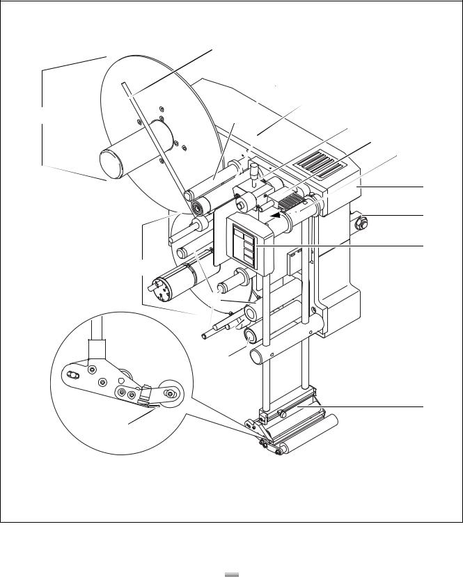
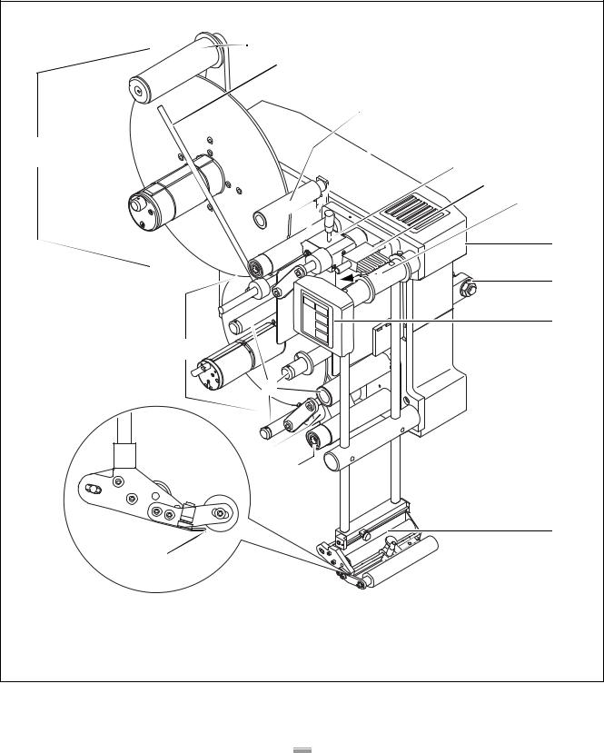
2.1.1 Structural elements
B |
C |
D |
A |
E |
F |
G |
H |
I |
J |
P |
O |
N |
M |
K |
L |
[2]Right-hand version of the ALS 350 Labeller
12

|
2 |
EQUIPMENT DESCRIPTION |
ALS |
|
2.1 |
OVERVIEW OF THE ALS 350 |
350 |
|
|
||
|
|
|
|
A Unwind unit
– The unwinding spindle holds the label roll.
B Guiding rod for unwind unit
– Secures the label roll on the unwinding spindle.
CUnwind unit deflection roller
DDrive roller unit of the unwind unit
–Pulls the label ribbon evenly from the label roll and transports it into the loop space.
E Pressure roller of the unwind unit
– Presses the label ribbon against the drive roller unit. F Braking brush
–Allows label ribbon to run smoothly, prevents fluttering.
G Loop space
–Shaft located below the pressure roller and the braking brush.
–In this area the label ribbon forms a loop.
H Casing
–Houses the control electronics, drive electrical system, main switch, and fuses.
–If equipped with optional water-resistant electronic control unit: the electronic control unit, drive electrical system, and electrical fuses are built into a separate switch cabinet.
I Mounting brackets
– For securing the machine in the system. J Operator panel
–Used to enter commands into the machine and to display operating states and error messages
–If equipped with optional water-resistant electronic control unit: the operator panel is built into a separate switch cabinet.
K Dispenser head
– Optionally equipped with printer or applicator
L Dispensing edge
– The label separates from the backing material here. M Drive roller unit of the label feed
–Pulls the label ribbon incrementally over the dispensing edge. A label is dispensed with each incremental movement.
N Label feed pressure roller
– Presses the label ribbon against the drive roller unit.
ORewind unit dancer arm and deflection rollers
– 3 fixed deflection rollers
– A spring-loaded, pivoting dancer arm
PRewind unit
–An electrically driven rewinding roller takes up the empty backing material.
–A spreader mechanism secures the backing material roll.
13
|
2 |
EQUIPMENT DESCRIPTION |
ALS |
|
2.1 |
OVERVIEW OF THE ALS 350 |
350 |
|
|
||
|
|
|
|
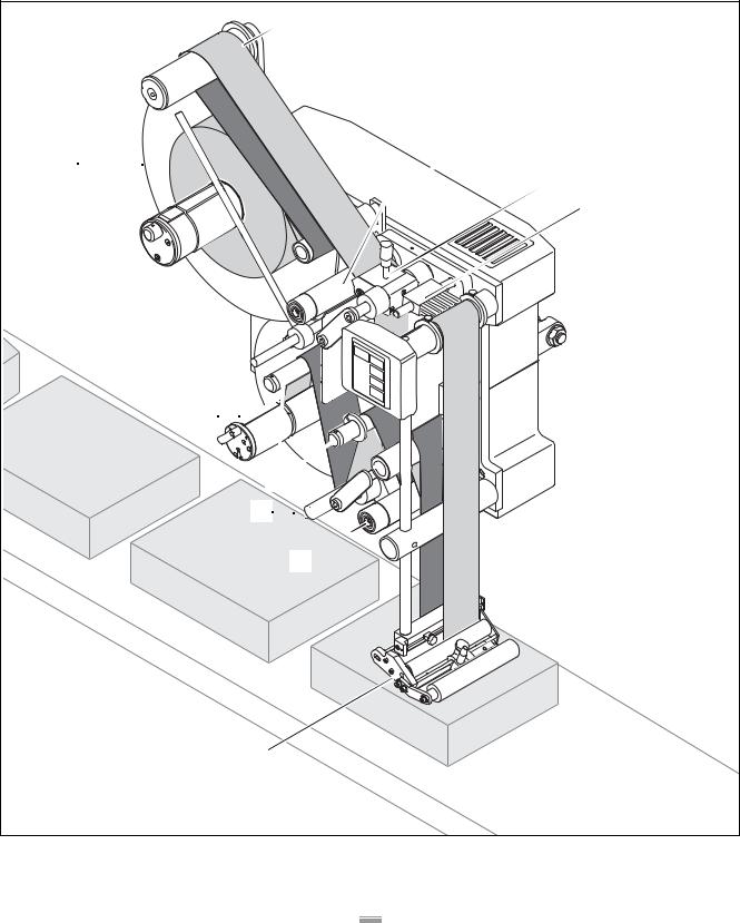
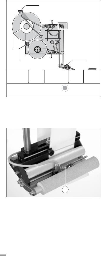
2.1.2 Principle of operation
 A
A
 B
B
 C
C
D
I 

H


G


F
E
[3]Labeller ALS 350 operationally ready with label ribbon
14

|
2 |
EQUIPMENT DESCRIPTION |
ALS |
|
2.1 |
OVERVIEW OF THE ALS 350 |
350 |
|
|
||
|
|
|
|
In labelling mode, the drive roller unit [2B] transports the label ribbon from the unwinding spool [2A]. A loop is formed in the label ribbon below the pressure roller of the unwind unit [2C] and the braking brush [2D]. The feed roller unit [2F] behind the dispenser head [2E] pulls the ribbon over the dispensing edge. The label separates from the backing material at the dispensing edge and is transferred onto the product.
The feed roller unit moves the respective ribbon for a label and then stops until the next product is transported to the dispensing edge. Label ribbon is continuously unwound at the unwind unit. The loop acts as a buffer between the continuously operating unwind unit and the periodically operating label output. The braking brushes keep the label ribbon taut.
From the dispensing head, the empty backing material runs over several deflection rollers [2H] and the springloaded, pivoting dancer arm [2G] to the motor-driven spreader rewinding unit [2I]. The multiple deflections with the spring-loaded dancer arm act as a buffer between the label output and the rewind unit. When in operation, the dancer arm pivots back and forth constantly.
The entire operation of the labeller is electronically controlled and monitored. If a malfunction occurs, the control system sends a corresponding message to the operator. If necessary, the labelling operation is automatically halted. An electronic signal is issued at the same time. The signal can be picked up and evaluated by an external control system.
15

|
2 |
EQUIPMENT DESCRIPTION |
ALS |
|
2.1 |
OVERVIEW OF THE ALS 350 |
350 |
|
|
||
|
|
|
|
2.1.3 Technical data
Characteristic values
Labelling speed: |
0.2 m/min to 55 m/min |
|
|
Labelling performance: |
Refer to the service guide |
|
|
Stop accuracy (at the |
|
dispensing edge): |
± 0.5 mm |
|
|
Unwind unit: |
Smooth unwinding spindle |
|
|
Rewind unit: |
Spreader mechanism |
|
|
Operation: |
Programmable, can be set |
|
via the operator panel, |
|
11 data bases available |
|
|
Speed control: |
Automatic dispensing |
|
speed, with RPM- |
|
transmitter |
|
|
Labels
Label width
(incl. backing material): 10 mm to 155 mm
Label length |
maximum 350 mm |
at maximum dispen- |
|
sing speed: |
16 mm to 250 mm |
|
|
Label roll |
|
Outer diameter: |
maximum 400 mm |
Core diameter: |
76.2 mm |
|
|
Casing
Covering for the control |
Polyurethane (PUR), |
electronics: |
10 mm thick |
|
|
Front plate: |
Aluminium, anodized, |
|
15 mm thick |
|
|
Electrical system
Power consumption: |
500 VA |
|
|
Mains connection |
|
Nominal voltage: |
110 V/120 V/130 V/200 V/ |
|
220 V/230 V/240 V 1) |
Frequency: |
50 Hz / 60 Hz 1) |
Type of protection |
|
IP41: |
protected against vertically |
|
falling drops of water, not |
|
protected against sprayed |
|
water |
IP54 (optional): |
Protected against splash- |
|
ing water and dust layers |
|
|
Drive system |
|
IP41: |
2 stepper motors, |
|
1 AC motor |
IP54 (optional): |
3 stepper motors |
|
|
1) Customer options |
|
Ambient conditions
Temperature |
|
Operation: |
5 °C to 40 °C |
Storage: |
5 °C to 70 °C |
|
|
Relative humidity: |
30 % to 80 %, |
|
not condensing |
|
|
Dimensions
Dimensions |
|
Width: |
735 mm |
Height: |
795 mm |
Depth: |
400 mm |
|
|
Weight |
70 kg |
|
|
Control system
Control electronics: |
|
|
IP41: |
Integrated |
|
IP54 (optional): |
The electronic control unit |
|
|
and operator panel are |
|
|
built into a separate switch |
|
|
cabinet |
|
|
|
|
Options: |
– |
Serial interface |
|
– |
Roll diameter control |
|
|
|
Emissions
Sound pressure level at |
|
a distance of 1 m: |
75 db (A) |
16
|
2 |
EQUIPMENT DESCRIPTION |
ALS |
|
2.1 |
OVERVIEW OF THE ALS 350 |
350 |
|
|
||
|
|
|
|
2.1.4 Design versions
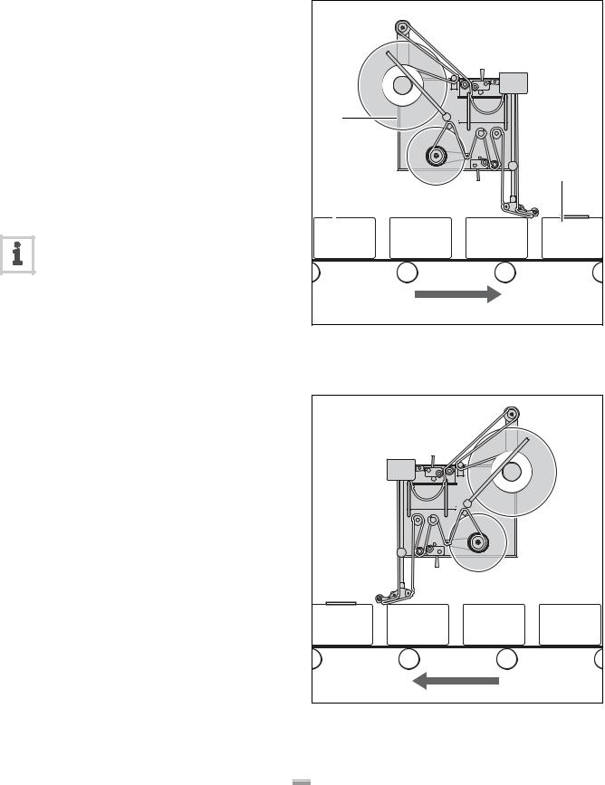
The ALS 350 labeller is available in 2 different versions, depending on the direction of the conveyor line:
Right-hand version
–The products are conveyed from left to right [4].
–The dispensing edge is located on the right side.
Left-hand version
–The products are conveyed from right to left [5].
–The dispensing edge is located on the left side.
Labeller operation is described in these instructions based on the right-hand design version. The left-hand version is only considered if its descriptions or illustrations differ significantly.
A |
|
B |
C |
[4]Right-hand version A ALS 350 labeller
B Product on conveyor line C Labelled product
[5]Left-hand version
17
|
2 |
EQUIPMENT DESCRIPTION |
ALS |
|
2.2 |
OVERVIEW OF THE ALS 450 |
450 |
|
|
||
|
|
|
|
2.2.1 Structural elements
B |
C |
D |
E |
A |
F |
G |
H |
I |
J |
K |
Q |
P |
O |
N |
L |
M |
[6]Right-hand version of the ALS 450 Labeller
18

|
2 |
EQUIPMENT DESCRIPTION |
ALS |
|
2.2 |
OVERVIEW OF THE ALS 450 |
450 |
|
|
||
|
|
|
|
A Unwind unit
–The unwinding spindle holds the label roll.
–A spreader mechanism secures the label roll.
BDancer arm of the unwind unit
– Spring-loaded and rotatable
– Assists in the flawless unwinding of the label ribbon from the unwinding spindle
CGuiding rod for unwind unit
– Secures the label roll on the unwinding spindle.
DUnwind unit deflection roller
EDrive roller unit of the unwind unit
–Pulls the label ribbon evenly from the label roll and transports it into the loop space.
F Pressure roller of the unwind unit
– Presses the label ribbon against the drive roller unit. G Braking brush
–Allows label ribbon to run smoothly, prevents fluttering.
H Loop space
–Shaft located below the pressure roller and the braking brush.
–In this area the label ribbon forms a loop.
I Casing
–Houses the control electronics, drive electrical system, main switch, and fuses.
–If equipped with optional water-resistant electronic control unit: the electronic control unit, drive electrical system, and electrical fuses are built into a separate switch cabinet.
J Mounting brackets
– For securing the machine in the system. K Operator panel
–Used to enter commands into the machine and to display operating states and error messages
–If equipped with optional water-resistant electronic control unit: the operator panel is built into a separate switch cabinet.
L Dispenser head
– Optionally equipped with printer or applicator
M Dispensing edge
– The label separates from the backing material here. N Drive roller unit of the label feed
–Pulls the label ribbon incrementally over the dispensing edge. A label is dispensed with each incremental movement.
O Label feed pressure roller
– Presses the label ribbon against the drive roller unit.
PRewind unit dancer arm and deflection rollers
– 3 fixed deflection rollers
– A spring-loaded, pivoting dancer arm
QRewind unit
–An electrically driven rewinding roller takes up the empty backing material.
–A spreader mechanism secures the backing material roll.
19
|
2 |
EQUIPMENT DESCRIPTION |
ALS |
|
2.2 |
OVERVIEW OF THE ALS 450 |
450 |
|
|
||
|
|
|
|
2.2.2 Principle of operation
 B
B
 C
C
A

 D
D
 E
E
J

I


H


G
F
[7]Labeller ALS 450 operationally ready with label ribbon
20
|
2 |
EQUIPMENT DESCRIPTION |
ALS |
|
2.2 |
OVERVIEW OF THE ALS 450 |
450 |
|
|
||
|
|
|
|
In labelling mode, the drive roller unit [7C] transports the label ribbon from the unwind mandrel [7A] around the dancer arm [7B]. The dancer arm keeps the label ribbon constantly taut and slightly under tension. A loop is formed in the label ribbon below the pressure roller of the unwind unit [7D] and the braking brush [7E]. The feed roller unit [7G] behind the dispenser head [7F] pulls the ribbon over the dispensing edge. The label separates from the backing material at the dispensing edge and is transferred onto the product.
The feed roller unit moves the respective ribbon for a label and then stops until the next product is transported to the dispensing edge. Label ribbon is continuously unwound at the unwind unit. The loop acts as a buffer between the continuously operating unwind unit and the periodically operating label output. The braking brushes keep the label ribbon taut.
From the dispensing head, the empty backing material runs over several deflection rollers [7I] and the springloaded, pivoting dancer arm [7H] to the motor-driven spreader rewinding unit [7J]. The multiple deflections with the spring-loaded dancer arm act as a buffer between the label output and the rewind unit. When in operation, the dancer arm pivots back and forth constantly.
The entire operation of the labeller is electronically controlled and monitored. If a malfunction occurs, the control system sends a corresponding message to the operator. If necessary, the labelling operation is automatically halted. An electronic signal is issued at the same time. The signal can be picked up and evaluated by an external control system.
21

|
2 |
EQUIPMENT DESCRIPTION |
ALS |
|
2.2 |
OVERVIEW OF THE ALS 450 |
450 |
|
|
||
|
|
|
|
2.2.3 Technical data
Characteristic values
Labelling speed: |
0.5 m/min to 55 m/min |
|
|
Labelling performance: |
Refer to the service guide |
|
|
Stop accuracy (at the |
|
dispensing edge): |
± 0.5 mm |
|
|
Unwind unit: |
Unwinding spindle with |
|
spreader mechanism |
|
|
Rewind unit: |
Spreader mechanism |
|
|
Operation: |
Programmable, can be set |
|
via the operator panel, |
|
11 data bases available |
|
|
Speed control: |
Automatic dispensing |
|
speed, with RPM- |
|
transmitter |
|
|
Labels
Label width
(incl. backing material): 10 mm to 230 mm
Label length |
maximum 350 mm |
at maximum dispen- |
|
sing speed: |
16 mm to 250 mm |
Label roll |
|
Outer diameter: |
maximum 400 mm |
Core diameter: |
76.2 mm |
Casing
Covering for the control- |
Polyurethane (PUR), |
electronics: |
10 mm thick |
|
|
Front plate: |
Aluminium, anodized, |
|
15 mm thick |
|
|
Electrical system
Power consumption: |
500 VA |
|
|
Mains connection |
|
Nominal voltage: |
110 V/120 V/130 V/200 V/ |
|
220 V/230 V/240 V 1) |
Frequency: |
50 Hz / 60 Hz 1) |
Type of protection |
|
IP41: |
protected against vertically |
|
falling drops of water, not |
|
protected against sprayed |
|
water |
IP54 (optional): |
Protected against splash- |
|
ing water and dust layers |
|
|
Drive system |
|
IP41: |
2 stepping motors, |
|
1 AC motor |
IP54 (optional): |
3 stepping motors |
|
|
1) Customer options |
|
Ambient conditions
Temperature |
|
Operation: |
5 °C to 40 °C |
Storage: |
5 °C to 70 °C |
|
|
Relative humidity: |
30 % to 80 %, |
|
not condensing |
|
|
Dimensions
Dimensions |
|
Width: |
735 mm |
Height: |
795 mm |
Depth: |
560 mm |
|
|
Weight |
85 kg |
|
|
Control system
Control electronics: |
|
|
IP41: |
Integrated |
|
IP54 (optional): |
The electronic control unit |
|
|
and operator panel are built |
|
|
into a separate switch cab- |
|
|
inet |
|
|
|
|
Options: |
– |
Serial interface |
|
– |
Roll diameter control |
|
|
|
Emissions
Sound pressure level at |
|
a distance of 1 m: |
75 db (A) |
22
|
2 |
EQUIPMENT DESCRIPTION |
ALS |
|
2.2 |
OVERVIEW OF THE ALS 450 |
450 |
|
|
||
|
|
|
|
2.2.4 Design versions
The ALS 450 labeller is available in 2 different versions, depending on the direction of the conveyor line:
Right-hand version
–The products are conveyed from left to right [8].
–The dispensing edge is located on the right side.
Left-hand version
–The products are conveyed from right to left [9].
–The dispensing edge is located on the left side.
Labeller operation is described in these instructions based on the right-hand design version. In general, the labeller ALS 350 (without dancer arm on the unwind unit) is depicted in the illustrations. The left-hand version and the ALS 450 are only considered if their descriptions or illustrations differ significantly.
A |
|
B |
C |
[8]Right-hand version A ALS 450 labeller
B Product on conveyor line C Labelled product
[9]Left-hand version
23

|
2 |
EQUIPMENT DESCRIPTION |
ALS |
|
2.3 |
OPTIONS |
350 |
|
450 |
||
|
|
|
|
|
|
|
|
Serial interface
–Almost all of the setting values can be read out and modified on an external device, the machine status can be queried, and the machine can be controlled via this interface.
–For further information, refer to the Service guide
Roll diameter control
–A sensor at the unwind unit monitors the diameter of the label roll and, along with it, the supply of labels.
–The sensor sends a signal when the diameter of the label roll reaches a set value.
–This sensor is required if two labellers are operating in tandem mode (see chapter Operation – Activation and shut-down, page 46)
Adjustable dispensing edge
–The position of the dispenser head can be adjusted vertically.
–This allows adapting the position of the dispensing edge to changing products.
–The machine does not have to be moved to adjust the dispensing edge, the labelling head of the machine does not have to be released.
Spring-loaded dispensing edge
–The dispensing edge is pivotably mounted onto the dispenser head. A torsion spring in the dispenser head presses the dispensing edge downward onto the surface of the product.
–Enables height differences between the products or surface characteristics differences to be compensated for.
Pneumatic dispensing edge
–The dispensing edge is pivotably mounted onto the dispenser head. Compressed air presses the dispensing edge downward onto the surface of the product.
–Enables height differences between the products or surface characteristics differences to be compensated for.
Printer
– Inkjet or heat transfer printer at the dispenser head.
Applicator
If direct labelling from the dispensing edge is not possible, the labeller can be equipped with an applicator. Various kinds of applicators are available depending on the customer’s needs.
Water-resistant electronic control unit
–Protected against splashing water as per type of protection IP54
–The control electronics, drive electrical system, electrical fuses and operator panel are built into a separate switch cabinet
–Driven exclusively by stepper motors
–Motors are protected against splashing water
24
2 EQUIPMENT DESCRIPTION
2.4 OPERATOR CONTROLS
2.4.1 Operator panel
LED indicator
–Display of functions, setting values, operating states, error messages, and warning messages
If the LED indicator is ON:
–The machine is in labelling mode.
–Each time the product sensor is triggered, a label is dispensed.
If the LED indicator is OFF:
– Labelling mode is switched off.
Keys
FEED
–When this key is pressed, the machine dispenses a label.
PRIOR (previous function)
–Paging through the functions in the menu: to see the previous function, page upward.
–Within a function: raise the current value, e.g. increase dispensing speed.
NEXT (next function)
–Paging through the functions in the menu: to see the next function, page downward.
–Within a function: reduce the current value, e.g. decrease dispensing speed.
ENTER
–Activate or switch off labelling mode.
–Call up or end functions.
–Acknowledge error and warning messages.
Depending on the menu and the operating state of the machine, special key functions are also available. Where special functions are available, they are described in the relevant chapter.
ALS 350 450
A
B
C
D
E
[10]Operator panel of the ALS 350 (same design as ALS 450 operator panel)
A LED indicator B FEED key
C PRIOR key D NEXT key E ENTER key
25
2 EQUIPMENT DESCRIPTION
2.4 OPERATOR CONTROLS
2.4.2 Main switch
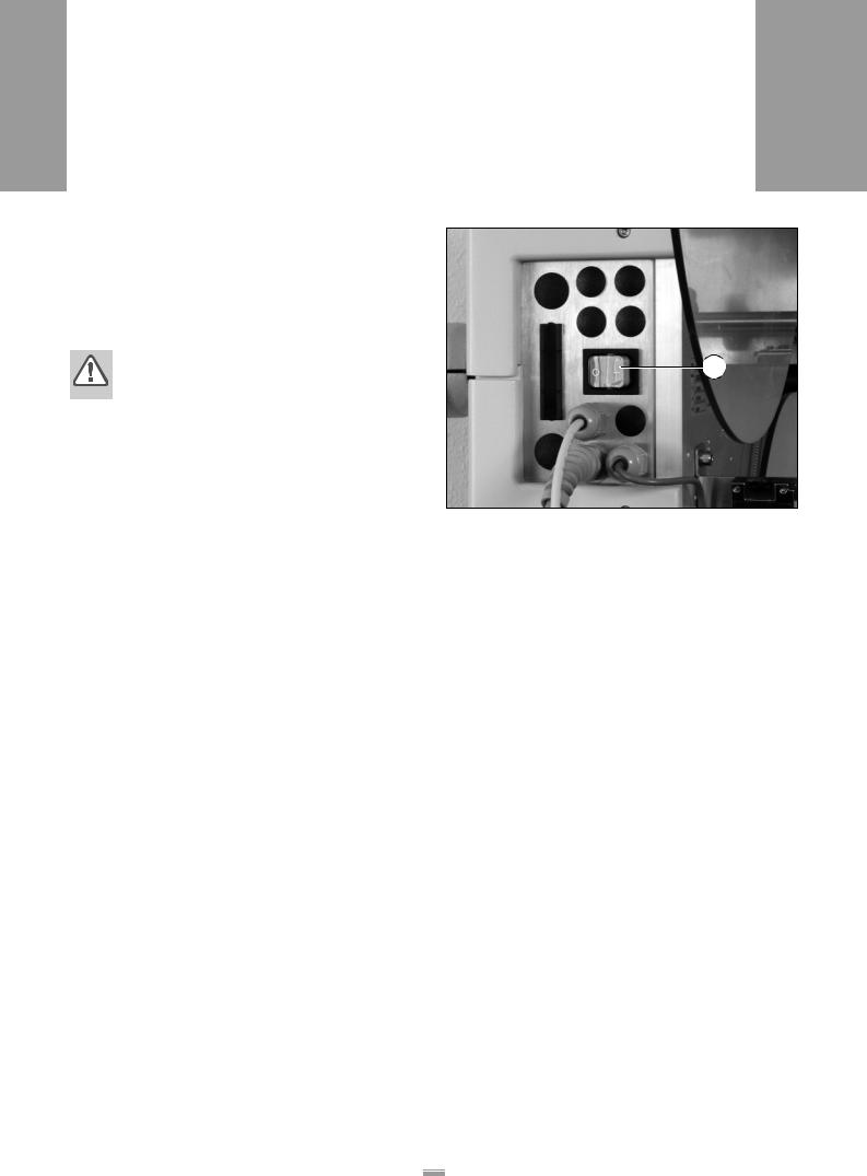
–The main switch [11] is located to the left on the housing.
–The main switch is used to switch the machine on and off.
WARNING!
Contact with energised components can result in life-endangering currents through the body as well as burns. Voltage continues to be present in the housing even when switched off.
Only put the machine into operation when installed in a correctly installed housing. Maintain the machine in a dry condition.
ALS 350 450
A
[11] Main switch on the housing
26

2 EQUIPMENT DESCRIPTION
2.5 CONTROL SYSTEM
2.5.1 Brief description
All of the machine’s functions are electronically controlled. Using the operator panel, the operators, calibration technicians, or service personnel have several options for adapting the machine's functions to current requirements.
The LED indicator gives the operator feedback messages regarding the current operating state of the machine. Error messages or warning messages appear on the display as necessary.
Before each operation, the operator must check and adjust the occasionally changing settings such as the label position on the product or the dispensing speed. These settings can simply be input at any time by the operator at the operator panel.
Task-specific data such as label distance or product length are programmed at the beginning of a job. As a rule, the settings are not modified as long as the job is being processed. This data input requires in-depth knowledge and may only be carried out by trained and instructed personnel (calibration technicians).
Databanks are available for variable or frequently recurring task settings. The task-specific settings can be saved in a databank. If the settings are needed again after a product change, it is not necessary to re-input the data. You only need to call up the corresponding databank. In all, 11 databanks are available.
Only calibration technicians may administer the product databanks.
ALS 350 450
It is also possible to modify the basic machine settings. These are settings such as the motor’s direction of rotation. These settings are not to be changed in normal operation. They may only be changed by servicing personnel or the customer service.
To give the operator a better overview, the setting options for occasionally changing settings, task-specific data, databanks, and basic settings are grouped together in menus: The standard menu, extended menu, product databanks, and configuration menu. The following table provides an overview of the range of functions of the standard menu, extended menu, and product databanks. The configuration menu is described in the service guide.
CAUTION!
Erroneous settings can lead to production setbacks, damage to the machine and sys-  tem, and can even cause work-related acci-
dents!
–Only specially trained and instructed personnel may alter the settings in the extended menu or access the product databanks.
27

|
2 |
EQUIPMENT DESCRIPTION |
ALS |
|
2.5 |
CONTROL SYSTEM |
350 |
|
450 |
||
|
|
|
|
|
|
|
|
2.5.2 Menus for operators and calibration technicians
Menu |
Standard menu |
|
Extended menu |
Product databanks |
|||
|
|
|
|
|
|
|
|
|
|
|
|
|
|
|
|
Functions |
ON |
|
ON |
|
ON |
||
|
|
|
|
|
|
|
|
|
OFF |
|
OFF |
|
OFF |
||
|
|
|
|
|
|
|
|
|
INIT |
INIT |
|
PD01 |
|||
|
|
|
|
|
|
|
|
|
VELO |
|
VELO |
|
PD02 |
||
|
|
|
|
|
|
|
|
|
STOD |
|
STOD |
|
PD03 |
||
|
|
|
|
|
|
|
|
|
POS |
|
POS |
PD04 |
|||
|
|
|
|
|
|
|
|
|
|
|
POS 2 |
PD05 |
|||
|
|
|
|
|
|
|
|
|
|
|
POS 3 |
PD06 |
|||
|
|
|
|
|
|
|
|
|
|
|
VERT |
|
PD07 |
||
|
|
|
|
|
|
|
|
|
|
|
CONT |
PD08 |
|||
|
|
|
|
|
|
|
|
|
|
|
E–SS |
|
PD09 |
||
|
|
|
|
|
|
|
|
|
|
|
LPIT |
|
PD10 |
||
|
|
|
|
|
|
|
|
|
|
|
PRDL |
PD11 |
|||
|
|
|
|
|
|
|
|
|
|
|
P_S_ |
|
|
|
|
|
|
|
|
|
|
|
|
|
|
|
S_S_ |
|
|
|
|
|
|
|
|
|
|
|
|
|
|
|
MLAB |
|
|
|
|
|
|
|
|
|
|
|
|
|
|
|
PDT |
|
|
|
|
|
|
|
|
|
|
|
|
|
|
|
PDWT |
|
|
|
|
|
|
|
|
|
|
|
|
|
|
|
EGRA |
|
|
|
|
|
|
|
|
|
|
|
|
|
|
|
TMOD |
|
|
|
|
|
|
|
|
|
|
|
|
|
|
|
APPL |
|
|
|
|
|
|
|
|
|
|
|
|
|
|
|
APT1 |
|
|
|
|
|
|
|
|
|
|
|
|
|
|
|
APT2 |
|
|
|
|
|
|
|
|
|
|
|
|
|
|
|
APT3 |
|
|
|
|
|
|
|
|
|
|
|
|
|
|
|
APT4 |
|
|
|
|
|
|
|
|
|
|
|
|
|
|
|
LOAD |
|
|
|
|
|
|
|
|
|
|
|
|
|
|
|
SAVE |
|
|
|
|
|
|
|
|
|
|
|
|
|
|
|
DEL |
|
|
|
|
|
|
|
|
|
|
|
|
|
|
|
QUIT |
|
|
|
|
|
|
|
|
|
|
|
|
|
|
|
|
|
|
|
|
Activating a |
Main switch + NEXT |
|
|
PRIOR + NEXT |
|
|
Main switch + |
|
|
|
|||||
|
|
|
|||||
menu |
|
|
|
|
|
|
PRIOR |
|
|
|
|
|
|
|
|
|
|
|
|
|
|
|
|
|
|
|
|
|
|
|
|
28
|
2 |
EQUIPMENT DESCRIPTION |
ALS |
|
2.5 |
CONTROL SYSTEM |
350 |
|
450 |
||
|
|
|
|
|
|
|
|
2.5.3 Monitoring functions
During labelling operation, the electronic control system and the sensors monitor the following functions.
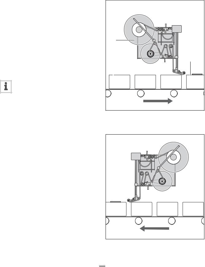
Dispensing a label to each product
–A photoelectric sensor (product sensor) sends a signal when a product reaches the dispensing
edge [12B]. The signal from the product sensor triggers the label feed for a single label.
–If individual labels are missing from the label ribbon, the label feed compensates for this and advances the label ribbon by one additional label distance (label compensation).
–If label compensation does not take place before the next start signal of the product sensor, the product does not get labelled. A warning message appears at the operator panel.
–If the number of unlabelled products exceeds a certain value, the machine stops.
Label supply
–If no more labels arrive at the label stop
sensor [12A] [13A], the machine stops and sends a signal to the output to the system controller.
–Roll diameter control (optional) [12D, E]:
If the diameter of the label roll on the unwinding spool [12C] becomes too small, the control system sends a warning message and a signal to the output to the system controller. The diameter at which the signal will be sent can be set by servicing technicians.
If errors occur
If a malfunction occurs, the control system sends a corresponding message to the operator. If necessary, the labelling operation is automatically halted. The machine simultaneously sends a signal to the system controller.
|
E |
C |
|
D |
A |
|
|
|
B |
[12]A Label stop sensor
B The product sensor sends a signal when the product has reached the dispensing edge.
C Label roll on the unwinding spool
D Photoelectric sensor of the optional roll diameter control E Reflector of the roll diameter control
A
[13] Backing material with a label under the label stop sensor (A)
29
|
3 |
PRIOR TO OPERATING |
ALS |
|
3.1 |
INSERT THE LABELLING MATERIAL – ALS 350 |
350 |
|
|
||
|
|
|
|
3.1.1 Prerequisites |
|
|
|
Verify flawless functioning of the safety equipment. |
|
Check machine for visible damage. Any discovered |
|
deficiency is to be reported immediately. |
A |
Non-required materials and objects are to be re- |
|
moved from the working area of the machine. |
|
Make sure that only persons authorised to work on |
|
the machine are within the working area of the ma- |
|
chine. |
|
Use required personal safety gear in accordance |
|
with the regulations, e. g. wear hair nets, and protec- |
[14] Main switch on the housing |
tive eye-glasses. |
|
– The label dispenser is switched off at the main |
|
|
|
[14A] switch. |
|
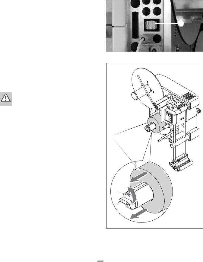
3.1.2 Insert the label roller |
|
|
|
WARNING! |
|
|
Risk of injury due to moving or rapidly rotat- |
|
|
ing parts! |
|
|
Before inserting the label roller, ensure |
|
|
that the machine is switched off at the |
|
|
main switch. |
|
|
Never switch on the machine before the la- |
|
|
bel ribbon has been completely threaded |
|
|
into position. |
A |
|
|
|
Remove the old backing material |
|
|
If backing material remains on the rewinding [15A] |
|
|
roller: |
|
|
|
Swing the lever [15C] at the rewinding roller over the |
|
|
red [15B] point. |
|
– The tension of the rewinding roller spreader mecha- |
|
|
|
nism is relieved. |
B |
|
Remove the rewound backing material. |
|
|
|
|
Remove adhesive residues |
|
|
|
If necessary, clean the following components: |
|
– |
Dispensing edge |
|
– |
Deflection rollers |
C |
– |
Drive roller |
|
– |
Rewinding roller |
|
Observe the notices in chapter Care and cleaning, Page 86.
[15]Remove the backing material from the rewinding roller A Old backing material
B Red point on the rewinding roller
C Lever for the spreader mechanism of the rewinding roller
30
Loading...