


 Loading...
OPERATING INSTRUCTIONS
Label Dispenser
ALS
204/206
256
Edition 04/2007

ALS
CONTENTS 20x
256
GB
1 Please note
1.1 General notes
1.1.1 Validity and binding effect of this manual . . . . 1
Contents . . . . . . . . . . . . . . . . . . . . . . . . . . . . . . . 1 Technical status . . . . . . . . . . . . . . . . . . . . . . . . . 1 Copyright . . . . . . . . . . . . . . . . . . . . . . . . . . . . . . . 1 Manufacturer . . . . . . . . . . . . . . . . . . . . . . . . . . . . 1
1.1.2 Illustrations and descriptions. . . . . . . . . . . . . . 2
Signs and symbols . . . . . . . . . . . . . . . . . . . . . . . 2 Dangers and risk notes . . . . . . . . . . . . . . . . . . . . 2 Figures . . . . . . . . . . . . . . . . . . . . . . . . . . . . . . . . 2 Button symbols . . . . . . . . . . . . . . . . . . . . . . . . . . 2 Parameters . . . . . . . . . . . . . . . . . . . . . . . . . . . . . 2 Supplementary information . . . . . . . . . . . . . . . . . 2
1.2 Safety instructions
1.2.1 Information and qualifications . . . . . . . . . . . . . 3
Follow the instructions. . . . . . . . . . . . . . . . . . . . . 3 Keep the product information at hand . . . . . . . . . 3 Ensure the required qualifications are met . . . . . 3
1.2.2 Operational safety of the unit . . . . . . . . . . . . . 4
Proper usage. . . . . . . . . . . . . . . . . . . . . . . . . . . . 4 Protection against injuries by electrical current . . 4 Protection against injuries by mechanical action. 5 Protection against injuries by chemicals . . . . . . . 5
1.2.3 Before beginning production . . . . . . . . . . . . . . 6
Due diligence of the operating company and the service technician . . . . . . . . . . . . . . . . . . . . . . . . 6 Due diligence of the user. . . . . . . . . . . . . . . . . . . 6
1.2.4 Safety notes on the unit . . . . . . . . . . . . . . . . . 7
2 Product description
2.1 Overview
2.1.1 Components . . . . . . . . . . . . . . . . . . . . . . . . . . 8
2.1.2 Control panel. . . . . . . . . . . . . . . . . . . . . . . . . 10
Operating LED. . . . . . . . . . . . . . . . . . . . . . . . . . 10 Error LED . . . . . . . . . . . . . . . . . . . . . . . . . . . . . 10 LCD display . . . . . . . . . . . . . . . . . . . . . . . . . . . . 10 Buttons . . . . . . . . . . . . . . . . . . . . . . . . . . . . . . . 10
2.1.3 Connection arrangement . . . . . . . . . . . . . . . 11
Connections on the back of the device . . . . . . . 11 Sensor connections. . . . . . . . . . . . . . . . . . . . . . 12
2.1.4 Mode of operation . . . . . . . . . . . . . . . . . . . . . 13
2.1.5 Technical specifications . . . . . . . . . . . . . . . . 14
Characteristics. . . . . . . . . . . . . . . . . . . . . . . . . . 14 Labels . . . . . . . . . . . . . . . . . . . . . . . . . . . . . . . . 14
i
Label sensor . . . . . . . . . . . . . . . . . . . . . . . . . . .14 Power supply . . . . . . . . . . . . . . . . . . . . . . . . . . .14 Electronics . . . . . . . . . . . . . . . . . . . . . . . . . . . . .15 Interfaces. . . . . . . . . . . . . . . . . . . . . . . . . . . . . .15 Internal Interfaces . . . . . . . . . . . . . . . . . . . . . . .15 Status messages, test functions,
product profiles . . . . . . . . . . . . . . . . . . . . . . . . .15 Dimensions . . . . . . . . . . . . . . . . . . . . . . . . . . . .16 Environmental conditions . . . . . . . . . . . . . . . . .16 Integration . . . . . . . . . . . . . . . . . . . . . . . . . . . . .16 Certificates. . . . . . . . . . . . . . . . . . . . . . . . . . . . .16
2.1.6 Design models . . . . . . . . . . . . . . . . . . . . . . . 17
Right-handed version . . . . . . . . . . . . . . . . . . . .17 Left-handed version. . . . . . . . . . . . . . . . . . . . . .17
2.2 Options
External control panel . . . . . . . . . . . . . . . . . . . .18 Fixed dispensing edge. . . . . . . . . . . . . . . . . . . .18 Swivelling dispensing edge . . . . . . . . . . . . . . . .18 Spring-loaded dispensing edge . . . . . . . . . . . . .18 Pneumatic dispensing edge . . . . . . . . . . . . . . .19 V-shape dispensing edge . . . . . . . . . . . . . . . . .19 Adjustable dispensing edge holder . . . . . . . . . .19 Outer Diameter control sensor . . . . . . . . . . . . .20 Printer . . . . . . . . . . . . . . . . . . . . . . . . . . . . . . . .20 Applicator. . . . . . . . . . . . . . . . . . . . . . . . . . . . . .20 Applicator interface . . . . . . . . . . . . . . . . . . . . . .20 Dust/Splash guard . . . . . . . . . . . . . . . . . . . . . . .20
2.3 Operating modes
2.3.1 Dispensing mode . . . . . . . . . . . . . . . . . . . . . 21
Stopping /Continuing the dispensing mode . . . .21 Changing the counter reading . . . . . . . . . . . . . .21 Starting the unit in configuration mode . . . . . . .21 Counting labels backwards . . . . . . . . . . . . . . . .21 Online settings. . . . . . . . . . . . . . . . . . . . . . . . . .22
2.3.2 Configuration mode . . . . . . . . . . . . . . . . . . . 23
Function of the double-arrow button . . . . . . . . .23 Menus . . . . . . . . . . . . . . . . . . . . . . . . . . . . . . . .23 Functions . . . . . . . . . . . . . . . . . . . . . . . . . . . . . .24
2.4 Function descriptions
2.4.1 Function overview . . . . . . . . . . . . . . . . . . . . 25 2.4.2 Notes on function descriptions. . . . . . . . . . . 27 2.4.3 LABEL SETUP menu. . . . . . . . . . . . . . . . . . 27 2.4.4 MACHINE SETUP menu . . . . . . . . . . . . . . . 27
2.4.5 SERVICE DATA menu. . . . . . . . . . . . . . . . . 28
> MODULE FW VERS. submenu . . . . . . . . . . .28 > OPERATIONAL DATA submenu . . . . . . . . . .28 >POWER SUPPLY DATA submenu . . . . . . . . .28

ALS
CONTENTS 20x
256
GB
> CPU BOARD DATA submenu . . . . . . . . . . . . 28 > DISPLAY DATA submenu . . . . . . . . . . . . . . . 28 > CF CARD SLOT submenu . . . . . . . . . . . . . . . 28 > PERIPHERAL DATA submenu . . . . . . . . . . . 28 >MEMORY DATA submenu . . . . . . . . . . . . . . . 28
3 Before operation
3.1 Electrical connections
3.1.1 Power supply connection . . . . . . . . . . . . . . . 29
Checking the power supply setting . . . . . . . . . . 30 Connecting the power cable.. . . . . . . . . . . . . . . 30
3.1.2 Connecting sensors . . . . . . . . . . . . . . . . . . . 31
Material end. . . . . . . . . . . . . . . . . . . . . . . . . . . .44 Material tear. . . . . . . . . . . . . . . . . . . . . . . . . . . .44
4.3 Using product profiles
4.3.1 What are product profiles?. . . . . . . . . . . . . . 45 4.3.2 Loading a product profile . . . . . . . . . . . . . . . 45
4.3.3 Storing a product profile. . . . . . . . . . . . . . . . 45
Selecting the memory location . . . . . . . . . . . . .45 Entering profile names. . . . . . . . . . . . . . . . . . . .45
4.3.4 Deleting a product profile . . . . . . . . . . . . . . . 46
5 After operation
3.2 Inserting label material
3.2.1 Prerequisites . . . . . . . . . . . . . . . . . . . . . . . . . 32
3.2.2 Inserting a label roll. . . . . . . . . . . . . . . . . . . . 33
Removing spent backing paper. . . . . . . . . . . . . 33 Removing glue residue . . . . . . . . . . . . . . . . . . . 33 Inserting a new label roll . . . . . . . . . . . . . . . . . . 33
3.2.3 Threading the label roll . . . . . . . . . . . . . . . . . 34
Threading guide . . . . . . . . . . . . . . . . . . . . . . . . 34 Threading the label roll at the dispensing edge. 35 Threading the label roll onto the drive roller . . . 36 Fastening the label roll to the rewinder . . . . . . . 36
3.3 Mechanical settings
3.3.1 Adjusting the unwinder’s core diameter . . . . 37 3.3.2 Positioning the pressure roller . . . . . . . . . . . 37 3.3.3 Positioning the label sensor . . . . . . . . . . . . . 38
4 Operation
4.1 Start-up and shutdown
4.1.1 Turning on the unit . . . . . . . . . . . . . . . . . . . . 39
4.1.2 Starting label dispensing. . . . . . . . . . . . . . . . 39
Dispensing with a product sensor . . . . . . . . . . . 39 Dispensing without a product sensor . . . . . . . . 39
4.1.3 Stopping the dispensing process . . . . . . . . . 40
5.1 Maintenance and cleaning
5.1.1 Replacing fuses . . . . . . . . . . . . . . . . . . . . . . 47 5.1.2 Cleaning agents . . . . . . . . . . . . . . . . . . . . . . 48
5.1.3 Regular maintenance. . . . . . . . . . . . . . . . . . 49
Removing paper debris . . . . . . . . . . . . . . . . . . .49 Renewal of the dust filter liner (ALS 256) . . . . .49
6 Operational failures
6.1 Error messages
6.1.1 Reporting errors . . . . . . . . . . . . . . . . . . . . . . 50 6.1.2 List of error messages . . . . . . . . . . . . . . . . . 50
7 Appendix
7.1 EU Declaration of Conformity
4.2 Configuration and monitoring
4.2.1 Function menu settings. . . . . . . . . . . . . . . . . 41
Label pitch . . . . . . . . . . . . . . . . . . . . . . . . . . . . . 41 Label stop position . . . . . . . . . . . . . . . . . . . . . . 41 Dispensing speed . . . . . . . . . . . . . . . . . . . . . . . 42 Label position on the product . . . . . . . . . . . . . . 43
4.2.2 Monitoring functions . . . . . . . . . . . . . . . . . . . 44
Missing labels . . . . . . . . . . . . . . . . . . . . . . . . . . 44
ii

|
|
CONTENTS |
ALS |
|
|
20x |
|
|
1.1 |
GENERAL NOTES |
256 |
|
GB |
||
|
|
|
|
|
|
|
|
1.1.1 |
Validity and binding effect of this manual |
|
|
Contents
The present manual refers exclusively to the ALS 204, ALS 206 and ALS 256 label dispensers. It is written for the purpose of ensuring professional usage and calibration of the unit.
Prerequisites for the use and adjustment are the professional installation and configuration of the unit.
For any technical questions you may have that are not described in this manual, see:
The service manual of the label dispenser or
Request a technician from one of our sales partners.
–Our sales representatives are available to assist you, particularly with configuring the unit as well as in the case of malfunctions.
Technical status
Technical status: 04/2007
Software version: 1.02
Avery Dennison reserves the right:
–To make modifications to construction parts, components and software, as well as to employ comparable components in place of the parts specified, in keeping with technical advances.
–To modify information in this document.
No commitment will be made to expand these modifications to include any units delivered earlier.
Copyright
Avery Dennison holds all rights to this manual and its appendices. Reproduction, reprinting or any other types of duplication, even of portions of this manual, may only be carried out with express written consent. Third persons, in particular competitors, should not be given access to the information in this manual.
Printed in Germany
Manufacturer
Avery Dennison Deutschland GmbH Ohmstrasse 3
85386 Eching, Germany
Phone: +49-8165-925-0 Fax: +49-8165-3143
http://www.machines.averydennison.com
1
CONTENTS
1.1 GENERAL NOTES
1.1.2 Illustrations and descriptions
Signs and symbols
Various information types are indicated in different ways within the document in order to simplify readability and comprehension.
Sentences starting with an arrow are instructions and guidelines.
Perform the instructions one after another in the specified order.
The following information begins with a dash:
–Lists
–Mode descriptions
–Descriptions of prior steps
–Prerequisites for following actions
Dangers and risk notes
Important directions that you must absolutely observe are particularly emphasized:
WARNING!
A warning refers to risks that can lead to serious injury or death! The warning contains safety measures to protect the relevant persons.
Always follow the instructions.
CAUTION!
A caution indicates risks that can lead to property damage or injuries to persons (minor injuries). The caution note contains instructions for preventing damages.
Always follow the instructions.
ALS 20x 256
GB
Figures
Texts are accompanied by figures where necessary. Figures are indicated using figure numbers in [square brackets]. A capital letter after a figure number, for example [12A], refers to a specific section of the figure. Generally, the label dispenser shown is an ALS 104 right-handed version. The left-handed version is only shown where it is necessary to differentiate between the two.
Button symbols
–The buttons of the control panel are depicted as symbols.
–The symbols are depicted with a ‘+’ (PLUS SIGN)
between them if more than one button is to be pressed.  +
+ 
Parameters
Parameters are displayed in grey in the text with the following structure, MENU NAME > Function name.
Supplementary information
The expert symbol indicates actions that are only to be performed by qualified and specially trained personnel.
The information symbol indicates notes and recommendations, as well as additional information.
Equipment:
–Equipment, for example lubricants or cleaning agents
2
CONTENTS
1.2 SAFETY INSTRUCTIONS
1.2.1 Information and qualifications
Follow the instructions
WARNING!
Safe and efficient operation of the label dispenser can only be guaranteed if you observe all necessary information.
Product liability and warranty claims can only be asserted if the unit was operated in accordance with the directions in the manual.
Before operating the unit, read the operating instructions and all other notes carefully.
Observe the additional safety and warning notes on the label dispenser. Only permit competent people to operate and configure the label dispenser.
Keep the product information at hand
With respect to this manual:
It should be kept at the location where the unit is installed and be available to the operator.
It should always be legible.
If the unit is sold, the manual should be made available to the new owner.
The safety and warning notes affixed to the unit itself must be kept clean and legible. Missing or damaged signs must be replaced.
ALS 20x 256
GB
Ensure the required qualifications are met
Ensure that only trained and authorized personnel operate, configure and service the unit.
Only allow qualified and well-trained expert personnel or service technicians to perform configurations.
The responsibilities with regard to operation, configuration and maintenance should be clearly defined and consistently maintained.
In addition, personnel should also be instructed on a regular basis in matters of occupational safety and environmental protection.
Qualification for operation
The instruction of personnel using the unit must ensure that:
–The operating personnel can use the unit on their own and safely.
–The operating personnel can remedy small operational disruptions on their own.
At least two people must be instructed in the unit’s usage.
Enough label material must be provided for testing and instructional purposes.
Qualifications for configuring
The configuration of the controls requires qualified expertise:
– Personnel configuring the unit must be acquainted with the functionality of the label dispenser.
–Personnel configuring the unit must be acquainted with the modes of operation within the facility in which the label dispenser is integrated.
–The personnel configuring the unit must be able to use the additional menus properly and appropriately for specific project requirements.
3
CONTENTS
1.2 SAFETY INSTRUCTIONS
1.2.2 Operational safety of the unit
Proper usage
The ALS 20x Label Dispenser is a fully automatic unit for attaching self-adhesive labels to products or packaging. The company operating the unit must install it with suitable equipment to protect operating personnel from danger; for example, the danger of the hands or fingers being crushed by reaching in between the product and the dispensing edge.
WARNING!
Improper usage of the unit can cause accidents, property damage and production downtime!
Only use the unit in accordance with the instructions specified in this manual. Do not operate the unit without the required safeguards.
Only configure the unit in accordance with this manual and with the required care.
Only use original accessories. Do not make any modifications or alterations to the unit.
Repairs to the device may only be performed by authorised specialists who are aware of the risks involved.
Protection against injuries by electrical current
WARNING!
The machine operates using mains voltage! Touching live electrical parts may expose you to hazardous electrical currents and may lead to burns.
Only operate the unit once the housing has been reassembled properly.
Only connect the unit to a properly fitted power socket that is grounded.
Before cleaning, switch off the unit and remove the power cable from the socket. Only link the unit to devices that fulfil the SELV (safety extra-low voltage) circuit requirements specified in EN 60950.
ALS 20x 256
GB
WARNING
The unit is not protected against splashing water in its standard model.
Keep the unit dry.
If liquids have penetrated the unit, switch it off and disconnect or unplug the power cable immediately. Inform a service technician.
WARNING
The device is only completely disconnected from the mains if the power cable is unplugged.
Make sure the power supply socket is accessible.
In case of emergency, switch off the device and disconnect the power cable.
CAUTION
A too high or low supply voltage can damage the unit.
Only operate the device using the system voltage indicated on the nameplate. Ensure that the mains voltage set on the unit is the same voltage as that provided by the electricity supplier.
4
CONTENTS
1.2 SAFETY INSTRUCTIONS
Protection against injuries by mechanical action
WARNING!
Risk of injury due to moving and rapidly rotating parts!
–Long hair, loose jewellery, long sleeves, and so on are not permissible when using the unit.
Sufficient protective clothing must be worn.
Keep moving parts free from obstructions even when the unit is not switched on, if there is a chance the machine might be turned on.
Switch off the machine before making any mechanical settings.
Do not wear ties, loose clothing, jewellery, wrist watches or similar items on your person when near the operating unit.
WARNING!
There is a risk that you may get your fingers or hands crushed on the dispensing edge by products on the conveyor belt!
Never reach between the product and the dispensing edge while the unit is in operation or ready for operation.
Never reach behind the safety guard or remove it while the unit is in operation.
Protection against injuries by chemicals
CAUTION!
Operating materials such as cleaning agents or the solvents in glues can be damaging to health.
Always follow the instructions, use and safety regulations specified by the manufacturer!
ALS 20x 256
GB
5

CONTENTS
1.2 SAFETY INSTRUCTIONS
1.2.3 Before beginning production
Due diligence of the operating company and the service technician
Ensure that the following prerequisites are fulfilled in accordance with the service instructions:
–The machine is installed properly and configured in accordance with the guidelines.
–All required safety mechanisms have been installed.
–The unit has performed at least one successful test run.
–The unit is connected to the power supply.
The users have the required personal protective equipment, for example, a hairnet. Ensure that the protective equipment is utilised correctly.
ALS 20x 256
GB
Due diligence of the user
Check that the safety installations are working properly.
Inspect the machinery for any visible damage. Report any ascertained defects immediately. Use the required personal protective equipment correctly, for example, wear a hairnet.
Remove any unnecessary materials and objects from the operating area of the unit.
Ensure that only authorised persons are within the operating range of the machine.
Ensure that starting up the machine will not injure anyone.
6
CONTENTS
1.2 SAFETY INSTRUCTIONS
1.2.4 Safety notes on the unit
CAUTION!
Warning notes on the unit represent important information for the personnel using it.
Do not remove warning notes. Replace any missing or illegible warnings.
The ‘Pinch Point’ warning [1] note warns you of the danger posed by the machine’s rotating parts; they can trap items and draw them in.
ALS 20x 256
GB
! WARNING |
Pinch point. |
Keep hands clear |
of rollers. |
A5346 |
[1]Left: ‘Pinch Point’ warning. Right: Position of the warning note on the ALS 20x. Item number of the label: A5346.
The blue label ‘Read manual’ [2] demands that users read the unit instructions.
Handbuch lesen!
Read the manual!
Lisez le manuel!
Lea el manual!
Legga il manuale!
[2]Left: ‘Read manual’ notice. Right: Position of the notice on the ALS 20x. Item number of the label: A5331.
7
|
|
CONTENTS |
|
|
ALS |
||||
|
|
|
|
20x |
|||||
|
|
2.1 OVERVIEW |
|
|
256 |
||||
|
|
|
|
GB |
|||||
|
|
|
|
|
|
|
|
||
|
|
2.1.1 Components |
|
|
|
|
|||
|
|
|
|
|
|
||||
|
|
|
|
|
|
|
|||
|
|
|
|
C |
D |
||||
|
|
|
B |
|
|
|
|
|
|
|
|
A |
|
|
|
|
|
|
|
|
|
|
|
|
|
|
|
||
|
|
|
|
|
|
|
|
|
|
|
|
|
|
|
|
|
|
|
|
|
|
|
|
|
|
|
|
|
|
E
F
O
N
M
L |
G |
|
K
H
I
J 
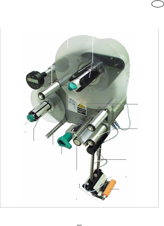
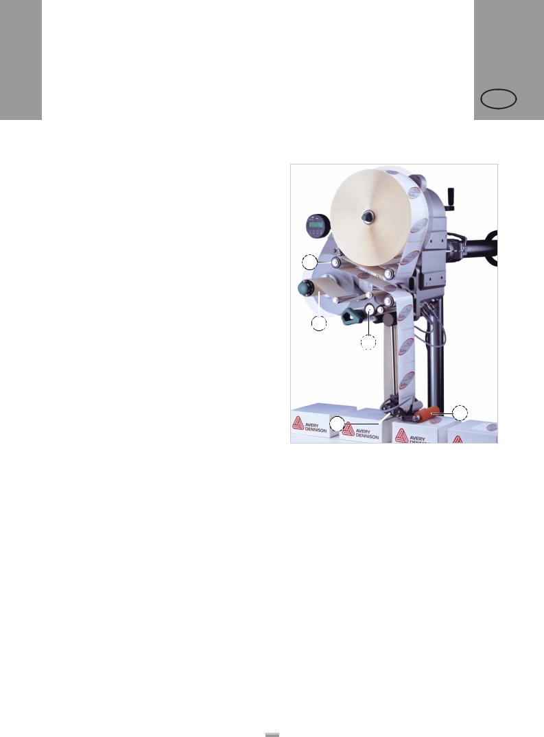
[3] ALS 204 Label Dispenser (right-handed version)
8

|
CONTENTS |
ALS |
|
20x |
|
|
2.1 OVERVIEW |
256 |
|
GB |
|
|
|
|
|
|
|
A Control panel
–For sending commands to the device and for displaying operating states and error messages.
–An optional external control panel can also be connected to the device.
B Dancer arm
–Keeps the label material stretched tight evenly.
–Arrests the rotation of the material roll if tension diminishes.
C Dispenser
– Dispenser mandrel grasps the label roll. D Core diameter adapter
–For adjusting the diameter of the dispenser mandrel to match the core diameter of the label roll.
E Adjusting knob
–Turning this in a clockwise direction secures the label roll on the dispenser.
FDeflection rollers
GDispensing edge bracket
HLabel sensor
–Stops the label feed after a label has been dispensed.
I Pressure roller
– Prints the label once it is stuck to the product.
J Dispensing edge
–Standard: (non-adjustable) L-shaped dispensing edge
–The following options are available: V-shaped dispensing edge, adjustable L-shaped dispensing edge, spring-loaded L-shaped dispensing edge, pneumatic L-shaped dispensing edge
K Drive roller
– Drives the label material forwards. L Pressure mechanism
–Presses the pressure roller against the drive roller.
–Prevents the backing paper from slipping through.
–Releases automatically once the backing paper has been drawn around the drive roller.
M Dancer arm
– Controls the rewind speed.
N Rewinder
– Rolls up the used backing paper. O Release button
–Pressing this button reduces the diameter of the rewinder core.
–Allows the easy removal of the rewound backing paper.
9
CONTENTS
2.1 OVERVIEW
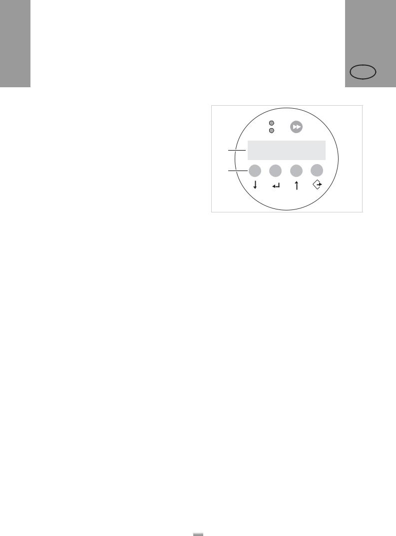
2.1.2 Control panel
Operating LED
Lights up green when the device is switched on.
Error LED
Lights up red when an error occurs.
LCD display
–Displays functions, configured values, operating states and error messages.
–What is displayed at any one time depends on the operating status of the device; these screens are explained in the section “Operating modes” on page 21.
Buttons
The functions of the buttons depend on the operating status of the device; these functions are explained in the section “Operating modes” on page 21.
ALS 20x 256
GB
A  ON
ON
B  STATUS
C |
|
Online |
|
Labels |
292 |
||
|
D – + – +
[4]The ALS 20x control panel (in dispensing mode) A Operating LED
B Error LED C LCD display D Buttons
10
|
|
CONTENTS |
ALS |
|
|
20x |
|
|
2.1 |
OVERVIEW |
256 |
|
GB |
||
|
|
|
|
|
|
|
|
2.1.3 |
Connection arrangement |
|
|
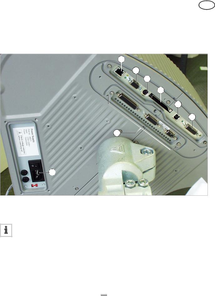
Connections on the back of the device
B
C
D
E
F
G
H
A
[5] Connections on the back of the device (ALS 20x): |
E Plug-in card slot (CompactFlash cards) |
A Power supply connection |
F USB device interface |
B Network connection (Ethernet 10/100) |
G PLC signal interface |
C Serial interface (RS232) |
H Optional: Applicator interface |
D Connection for external control panel (RS485) |
|
For information on connecting the unit, see section “Power supply connection” on page 29.
11
|
CONTENTS |
ALS |
||
|
20x |
|||
|
2.1 OVERVIEW |
256 |
||
|
GB |
|||
|
|
|
||
|
Sensor connections |
|
|
|
|
|
|
|
|
|
|
|
|
|
|
|
|
|
|
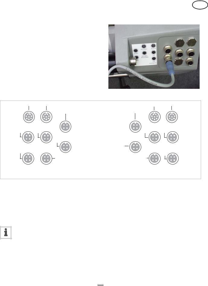
[6] Sensor connections on the ALS 20x (RH)
C |
B |
|
B |
C |
|
A |
|
A |
|
PLC-IN |
PLC-OUT |
|
PLC-OUT |
PLC-IN |
E |
D |
|
D |
E |
LH |
START |
|
START |
RH |
|
F |
F |
|
|
OD |
ROTARY |
ROTARY |
OD |
|
G |
ENCODER |
|
ENCODER |
G |
|
H LABEL |
|
LABEL H |
|
CAP |
CAP for 256 |
|
CAP for 256 CAP |
|
[7]Arrangement of the sensor connections (schematic) on the LH (left figure) and RH (right figure) devices:
A Product sensor
B Signal outputs (optional) C Signal inputs (optional)
D Rotary encoder (for automatic speed adaption) E Roll diameter sensor
F Label sensor
G (ALS 20x) Alternative label sensor H (ALS 256) Alternative label sensor
For information on connecting the sensors, see section “Connecting sensors” on page 31.
12
CONTENTS
2.1 OVERVIEW
2.1.4 Mode of operation
In labelling mode, the strip is first pulled from the label roll around the dancer arm [8A], which consistently maintains even tension in the label strip. The feed roller [8D] behind the dispensing edge [8C] draws the strip across the dispensing plate. The label is unfixed from the backing paper on the dispensing plate and is pressed onto the product by the pressure roller [8B].
The feed roller drives the label strip forwards the length of one label and stops until the next product arrives at the dispensing plate. The strip feed is started by the product sensor mounted on the conveyor belt. The stop control provided by the label sensor on the dispensing edge ensures the feed is halted as soon as a gap is detected between two labels.
The spent backing paper runs from the dispensing edge around the drive roller [8D] to the rewinder [8E]. The dancer arm regulates the rewinding speed.
The entire operation of the label dispenser is controlled and monitored electronically. If errors occur, the device controls output an appropriate notification for the operator. If necessary, the labelling operating mode is halted automatically. An electronic signal is output at the same time. The signal can be fed to an external controller and evaluated.
ALS 20x 256
GB
A
E
D
B
C
[8]The ALS 20x Label Dispenser is ready for operation in its idle mode.
A Dancer arm
B Pressure roller C Dispensing edge D Drive roller
E Rewinder
13

CONTENTS
2.1 OVERVIEW
2.1.5 Technical specifications
Characteristics
Dispensing speed 1): |
|
ALS 204 |
max. 40 m/min |
ALS 206 |
max. 30 m/min |
ALS 256 |
max. 50 m/min |
|
|
Labelling halt precision 2) |
±1 mm |
at the peeling edge: |
|
|
|
Speed control: |
Fixed setting or automatic |
|
speed adaption via the |
|
rotary encoder |
1)The maximum usable dispensing speed depends on the label geometry. For details see separate performance matrix.
2)At a dispensing speed range of 5 m/min to the max. speed
Labels
Label material: |
Converted self-adhesive |
|
label material with liner |
|
|
Internal rewinding |
yes |
|
|
Material width (including |
|
backing paper) 3): |
|
ALS 204 |
up to 110 mm |
ALS 206 |
up to 160 mm |
ALS 256 |
up to 160 mm |
|
|
Label length: |
5 to 600 mm |
|
|
Label roll: |
|
Winding direction |
inner or outer |
Dispenser (outer) Ø: |
up to 300 mm |
Rewinder (outer) Ø: |
up to 200 mm |
Core (inner) Ø: |
38.1 / 76.2 / 101.6 mm |
|
(1.5 / 3 / 4 ") |
3) Depending on the dispensing edge width.
ALS 20x 256
GB
Label sensor
Distance to peel edge |
|
L-shape dispensing |
|
edge: |
19 mm |
V-shape dispensing |
|
edge: |
77 mm |
|
|
Transmission sensor: |
Wenglor OPT242-P800 |
|
optical, NPN |
|
|
Power supply
System voltage: |
|
ALS 20X |
110 V (AC) at 60 Hz pow- |
|
er frequency (permissible |
|
tolerance ±10%) |
|
230 V (AC) at 50 Hz pow- |
|
er frequency (permissible |
|
tolerance ±10%) |
ALS 256 |
100-240 V (AC) at |
|
50-60 Hz power frequen- |
|
cy (permissible tolerance |
|
±10%) |
|
|
Power consumption: |
|
ALS 20X |
max. 460 VA |
ALS 256 |
max. 560 VA |
|
|
Fuses: |
|
ALS 20X |
F1, F2: T5AH 250 V 4) |
ALS 256 |
Fuses integrated in the |
|
power supply 5) |
4)For more information on fuses, see section “Replacing fuses” on page 47.
5)Not accessible for user or service technician.
14
Loading...