

Page 1

R
P/I P65UP8
Baseboard for CPU Cards
USER’S MANUAL
Page 2

USER'S NOTICE
No part of this manual, including the products and software described in it, may be reproduced, transmitted, transcribed, stored in a retrieval system, or translated into any language
in any form or by any means, except documentation kept by the purchaser for backup purposes, without the express written permission of ASUSTeK COMPUTER INC. (“ASUS”).
ASUS PROVIDES THIS MANUAL “AS IS” WITHOUT WARRANTY OF ANY KIND,
EITHER EXPRESS OR IMPLIED, INCLUDING BUT NOT LIMITED TO THE IMPLIED
W ARRANTIES OR CONDITIONS OF MERCHANTABILITY OR FITNESS FOR A PARTICULAR PURPOSE. IN NO EVENT SHALL ASUS, ITS DIRECTORS, OFFICERS,
EMPLOYEES OR AGENTS BE LIABLE FOR ANY INDIRECT, SPECIAL, INCIDENTAL, OR CONSEQUENTIAL DAMAGES (INCLUDING DAMAGES FOR LOSS OF
PROFITS, LOSS OF BUSINESS, LOSS OF USE OR DATA, INTERRUPTION OF BUSINESS AND THE LIKE), EVEN IF ASUS HAS BEEN ADVISED OF THE POSSIBILITY
OF SUCH DAMAGES ARISING FROM ANY DEFECT OR ERROR IN THIS MANUAL
OR PRODUCT.
Product warranty or service will not be extended if: (1) the product is repaired, modified or
altered, unless such repair, modification of alteration is authorized in writing by ASUS; or
(2) the serial number of the product is defaced or missing.
Products and corporate names appearing in this manual may or may not be registered trademarks or copyrights of their respective companies, and are used only for identification or
explanation and to the owners’ benefit, without intent to infringe.
• Intel, LANDesk, and Pentium are registered trademarks of Intel Corporation.
• IBM and OS/2 are registered trademarks of International Business Machines.
• Symbios is a registered trademark of Symbios Logic Corporation.
• Windows and MS-DOS are registered trademarks of Microsoft Corporation.
• Sound Blaster AWE32 and SB16 are trademarks of Creative Technology Ltd.
• Adobe and Acrobat are registered trademarks of Adobe Systems Incorporated.
The product name and revision number are both printed on the product itself. Manual revi-
sions are released for each product design represented by the digit before and after the period
of the manual revision number. Manual updates are represented by the third digit in the
manual revision number.
For previous or updated manuals, BIOS, drivers, or product release information, contact ASUS
at http://www.asus.com.tw or through any of the means indicated on the following page.
SPECIFICATIONS AND INFORMATION CONTAINED IN THIS MANUAL ARE FURNISHED FOR INFORMATIONAL USE ONLY, AND ARE SUBJECT TO CHANGE AT
ANY TIME WITHOUT NOTICE, AND SHOULD NOT BE CONSTRUED AS A COMMITMENT BY ASUS. ASUS ASSUMES NO RESPONSIBILITY OR LIABILITY FOR
ANY ERRORS OR INACCURACIES THA T MA Y APPEAR IN THIS MANUAL, INCLUDING THE PRODUCTS AND SOFTWARE DESCRIBED IN IT.
Copyright © 1997 ASUSTeK COMPUTER INC. All Rights Reserved.
Product Name: P/I-P65UP8
Manual Revision: 1.03
Release Date: November 1997
2
ASUS P/I-P65UP8 User’s Manual
Page 3

ASUS CONTACT INFORMATION
ASUSTeK COMPUTER INC.
Marketing Info
Address: 150 Li-Te Road, Peitou, Taipei, Taiwan 112, ROC
Telephone: +886-2-894-3447
Fax: +886-2-894-3449
Email: info@asus.com.tw
Technical Support
Fax: +886-2-895-9254
BBS: +886-2-896-4667
Email: tsd@asus.com.tw
WWW: www.asus.com.tw
Gopher: gopher.asus.com.tw
FTP: ftp.asus.com.tw/pub/ASUS
ASUS COMPUTER INTERNATIONAL
Marketing Info
Address: 721 Charcot Avenue, San Jose, CA 95131, USA
Telephone: +1-408-474-0567
Fax: +1-408-474-0568
Email: info-usa@asus.com.tw
Technical Support
BBS: +1-408-474-0569
Email: tsd-usa@asus.com.tw
WWW: www.asus.com
ASUS COMPUTER GmbH
Marketing Info
Address: Harkort Str. 25, 40880 Ratingen, BRD, Germany
Telephone: 49-2102-445011
Fax: 49-2102-442066
Email: info-ger@asus.com.tw
Technical Support
Hotline: 49-2102-499712
BBS: 49-2102-448690
Email: tsd-ger@asus.com.tw
WWW: www.asuscom.de
FTP: ftp.asuscom.de/pub/ASUSCOM
ASUS P/I-P65UP8 User’s Manual 3
Page 4

CONTENTS
I. INTRODUCTION.........................................................7
How this Manual is Organized ........................................................7
Item Checklist ..................................................................................7
Features of the ASUS P/I-P65UP8 Baseboard ................................8
II. FEATURES ..................................................................8
Parts of the ASUS Baseboard ..........................................................9
III. INSTALLATION .....................................................10
ASUS Baseboard Layout ...............................................................10
Installation Steps............................................................................12
1. Jumpers ......................................................................................12
Jumper Settings ..................................................................13
2. System Memory (DRAM) ........................................................18
DRAM Memory Installation Procedures .................................19
3. Central Processing Unit ............................................................20
System Case........................................................................20
4. Expansion Cards .......................................................................22
Expansion Card Installation Procedure ..............................22
Assigning IRQs for Expansion Cards.................................22
Assigning DMA Channels for ISA Cards...........................23
5. External Connectors..................................................................24
IV. VGA Installation .......................................................33
Windows 95 Video Driver Installation ..........................................33
Windows 95 Video Driver Installation ..........................................34
Using Control Panel .................................................................34
Windows 95 Display Settings........................................................35
Windows NT 4.0 Video Driver Installation ...................................37
Windows NT 3.51 Video Driver Installation .................................38
IBM OS/2 Video Driver Installation..............................................39
AutoCAD Video Driver Installation ..............................................39
Microstation Video Driver Installation ..........................................39
4
ASUS P/I-P65UP8 User’s Manual
Page 5

(This page was intentionally left blank.)
ASUS P/I-P65UP8 User’s Manual 5
Page 6

FCC & DOC COMPLIANCE
Federal Communications Commission Statement
This device complies with FCC Rules Part 15. Operation is subject to the following
two conditions:
• This device may not cause harmful interference, and
• This device must accept any interference received, including
interference that may cause undesired operation.
This equipment has been tested and found to comply with the limits for a Class B
digital device, pursuant to Part 15 of the FCC Rules. These limits are designed to
provide reasonable protection against harmful interference in a residential installation. This equipment generates, uses and can radiate radio frequency energy and, if
not installed and used in accordance with manufacturer's instructions, may cause
harmful interference to radio communications. However, there is no guarantee that
interference will not occur in a particular installation. If this equipment does cause
harmful interference to radio or television reception, which can be determined by
turning the equipment off and on, the user is encouraged to try to correct the interference by one or more of the following measures:
• Re-orient or relocate the receiving antenna.
• Increase the separation between the equipment and receiver.
• Connect the equipment to an outlet on a circuit different from
that to which the receiver is connected.
• Consult the dealer or an experienced radio/TV technician for help.
WARNING! The use of shielded cables for connection of the monitor to the
graphics card is required to assure compliance with FCC regulations. Changes
or modifications to this unit not expressly approved by the party responsible for
compliance could void the user's authority to operate this equipment.
Canadian Department of Communications Statement
This digital apparatus does not exceed the Class B limits for radio noise emissions
from digital apparatus set out in the Radio Interference Regulations of the Canadian Department of Communications.
6
ASUS P/I-P65UP8 User’s Manual
Page 7
I. INTRODUCTION
How this Manual is Organized
This manual is divided into the following sections:
I. Introduction: Manual information and checklist
II. Features: Information and specifications concerning this product
III.Installation: Instructions on setting up the baseboard
IV. VGA Installation: Instructions on setting up the onboard VGA
Item Checklist
Please check that your package is complete. If you discover damaged or missing
items, please contact your retailer.
(1) ASUS Baseboard
(1) 9pin male serial + 25pin male serial external connector set
I. INTRODUCTION
(Manual / Checklist)
(1) 25pin female parallel + 6pin female PS/2 mouse external connector set
(1) IDE ribbon cable for master and slave drives
(1) Floppy ribbon cable for (1) 5.25inch floppy and (2) 3.5inch floppies
(1) bag of spare jumpers
(1) Motherboard User’s Manual
(1) SCSI Utilities User’s Manual
(1) C-P6ND or C-PKND CPU card
(1) Infrared module (optional)
ASUS P/I-P65UP8 User’s Manual 7
Page 8

II. FEATURES
Features of the ASUS P/I-P65UP8 Baseboard
The P/I-P65UP8 is carefully designed for the demanding PC user who wants great
versatility in a computer system. This baseboard:
• V ersatile Processor Support: Supports dual 150–200MHz Pentium Pro or dual
233–333MHz Pentium II processors.
• I2O: Includes onboard Intel’s i960RD I/O processor with 32KB NVRAM,
2x512KB Flash EPROM, and 2SIMM slots for up to 256MB memory.
II. FEATURES
(Features)
• VGA: Includes onboard S3Trio64 VGA with 1MB DRAM upgradable to 2MB.
• SCSI: Includes onboard Adaptec AIC 7880 for one primary and Symbios 53C896
for two secondary SCSI channes for a maximum of 45 SCSI devices.
• Dual Power Supply: Has both AT and ATX power connectors onboard to sup-
port an AT or ATX power supply with soft-on/off features.
• Versatile DRAM Memory Support: Supports eight 72-pin SIMMs of 4MB,
8MB, 16MB, 32MB, 64MB, 128MB to form a memory size between 8MB to
1GB. Supports both Fast Page Mode (FPM), and Extended Data Output (EDO)
SIMMs. Burst Extended Data Output (BEDO) supported with the C-P6ND CPU
card.
• ISA and PCI Expansion Slots: Provides three 16-bit ISA slots and seven 32-bit
PCI slots.
• Super Multi-I/O: Provides two high-speed UART-compatible serial ports and
one parallel port with EPP and ECP capabilities. Supports two of either 5.25- or
3.5-inch disk drives (1.44MB or 2.88MB) without an external card.
• PCI Bus Master IDE Controller: Comes with an onboard PCI Bus Master
IDE controller with two connectors that supports four IDE devices in two channels, supports PIO Modes 3 and 4 and Bus Master IDE DMA Mode 2, and
supports Enhanced IDE devices such as Tape Backup and CD-ROM drives.
Supports two drives of either 5.25-inch (360KB or 1.2MB) or 3.5-inch (720KB,
1.44MB, or 2.88MB) disk drives. Supports Japanese “Floppy 3 mode” (3.5inch disk drive: 1.2MB) and LS-120 floppy disk drives (3.5-inch disk drive: 120
MB, 1.44MB, 720K). BIOS supports IDE CD-ROM or SCSI device boot-up.
• Desktop Management Interface (DMI): Supports DMI through BIOS which
allows hardware to communicate within a standard protocol creating a higher
level of compatibility. (Requires DMI-enabled components.)
• Easy Installation: Is equipped with BIOS that supports auto detection of hard
drives, PS/2 mouse, and Plug and Play devices to make setup of hard drives,
expansion cards, and other devices virtually automatic.
• Optional IrDA Module: Supports an optional infrared port module for wireless
file transfers and communication.
8 ASUS P/I-P65UP8 User’s Manual
Page 9
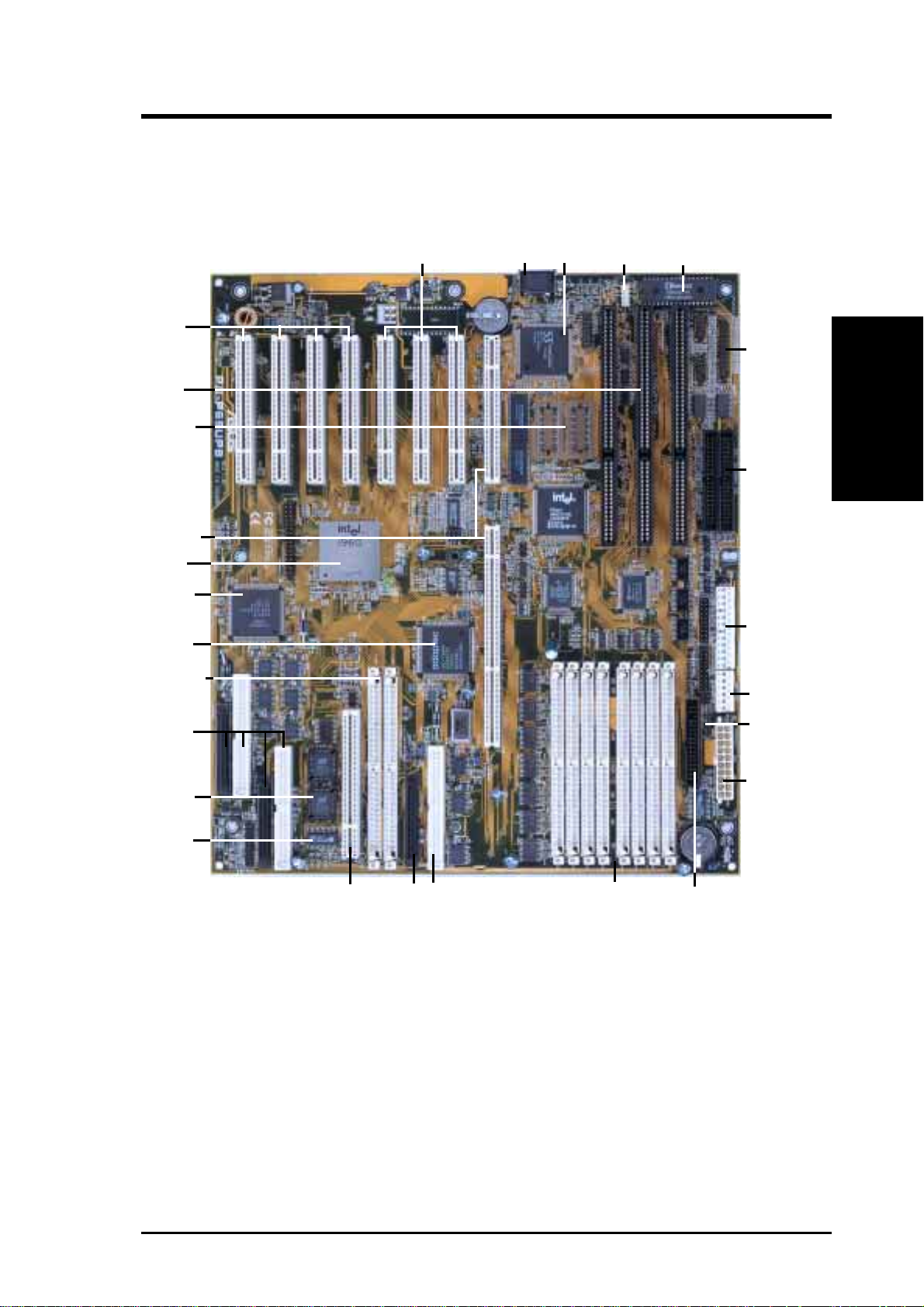
II. FEATURES
Parts of the ASUS Baseboard
4 Secondary
PCI Slots
3 ISA Slots
Onboard VGA
memory sockets
CPU Card Slot
Intel i960RD
Symbios SCSI
Adaptec SCSI
72-pin SIMM I2O
Memory Sockets
Symbios Dual
SCSI Channel
Connectors
i960 Firmware
3 Primary
PCI Slots
Keyboard
Onboard
S3 VGA
Universal
Serial Bus
Programmable
Flash ROM
Parallel &
Serial
Connectors
IDE 1 & 2
Connectors
AT Power
Connector
AT Aux. Pwr.
Connector
Infrared Module
Support
ATX Power
Connector
II. FEATURES
(Parts of Board)
i960 NVRAM
I2O Expansion Slot
(Reserved for future)
Adaptec Single
SCSI Channel
Connectors
(8) 72-pin SIMM
System Memory
Sockets
Floppy
Connector
ASUS P/I-P65UP8 User’s Manual 9
Page 10
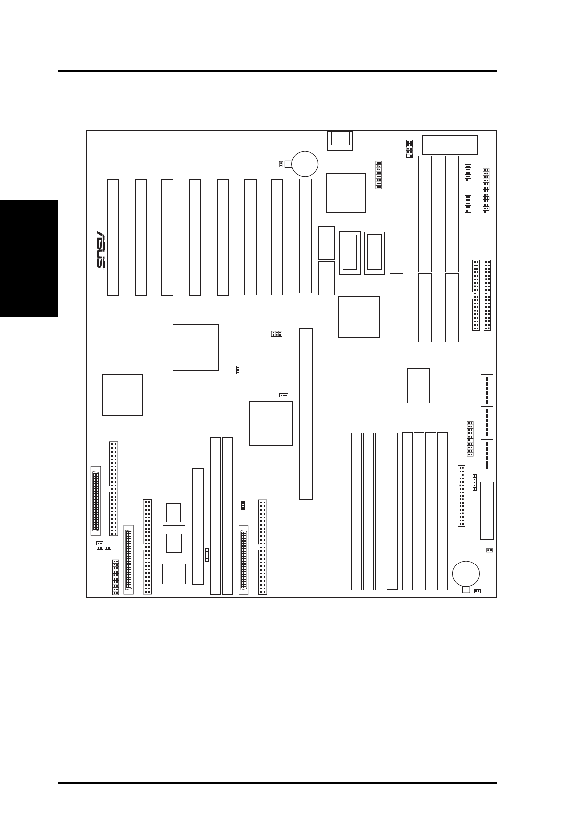
III. INSTALLATION
ASUS Baseboard Layout
III. INSTALLATION
(Board Layout)
HDLED A
HDLED B
Secondary PCI Slot 3
Secondary PCI Slot 4
R
Symbios
Logic
SCSI
Chipset
Symbios Ch B Connectors
35
1
Symbios Ch A Connectors
35
HDLED
1
Case Connector
34
68
34
68
PCI Slot 3
Secondary PCI Slot 1
Secondary PCI Slot 2
Intel
i960
Chipset
SIMM Socket 1 (Bank 0)
I2O Expansion Slot (Reserved)
i960’s
Firmware
i960’s
Firmware
Battery Con.
i960’s
NVRAM
JP2
PCI Slot 2
PCI Slot 1
FS1
FS2
FS0
960SEL
7880IDSEL
Adaptec
SCSI
Chipset
SIMM Socket 2 (Bank 1)
DRAMRAS
Adaptec 7880 Connectors
35
1
34
68
CMOS Power
3Volts
CR2032
Lithium Cell
CPU Card Slot
CPU Card Slot
Keyboard
S3 VGA
Chipset
512KB DRAM
for onboard VGA
512KB DRAM
for onboard VGA
Universal Serial Bus
ISA Slot 3
512KB DRAM
for onboard VGA
512KB DRAM
for onboard VGA
Intel
Chipset
SIMM Socket 3 (Bank 2)
SIMM Socket 4 (Bank 3)
SIMM Socket 2 (Bank 1)
SIMM Socket 1 (Bank 0)
2Mbit Flash EEPROM
(Programable BIOS)
ISA Slot 2
COM 1
ISA Slot 1
COM 2
Multi-I/O
Chip
Server Conn.
SIMM Socket 7 (Bank 2)
SIMM Socket 8 (Bank 3)
SIMM Socket 6 (Bank 1)
SIMM Socket 5 (Bank 0)
Floppy Drives
CR2032 3Volts
Lithium Cell
BIOS Power
Serial Ports
Parallel Port
Primary IDE
Secondary IDE
Main Power Input
P9P8
Aux. Pwr In.
P10
Infrared
ATX Power Input
RTC RAM
Battery Test
JP1
10 ASUS P/I-P65UP8 User’s Manual
Page 11

III. INSTALLATION
Jumpers
1) 960SEL p. 13 i960 Setting (I2O/Bridge)
2) DRAMRAS p. 13 DRAM RAS Setting (Single/Double)
3) 7880IDSEL p. 14 Adaptec 7880 ID Setting (9/15)
4) R TCLR p. 15 Real T ime Clock RAM (Operation/Clear CMOS)
5) JP1, JP2 p. 15 Battery Test Leads
6) FS0, FS1, FS2 p. 16 CPU External Frequency (BUS) Selection
Expansion Slots
1) SIMM1–SIMM8 p. 18 72-Pin SIMM System Memory Sockets
2) I -SIMM1, I–SIMM2 p. 18 72-Pin SIMM i960 Memory Sockets
3) CPU1, CPU2 p. 20 Central Processing Unit (CPU) Card Slot
4) PCI1-3, Secondary PCI1-4 p. 22 32-bit PCI and I2O Bus Expansion Slots
5) SLOT1, SLOT2, SLOT3 p. 23 16-bit ISA Bus Expansion Slots
Connectors
(Board Layout)
III. INSTALLATION
1) KB p. 24 Keyboard Connector (5-pin female)
2) FLOPPY p. 24 Floppy Disk Drive Connector (34-pin block)
3) PRINTER p. 25 Parallel Port Connector (26-pin block)
4) COM1, COM2 p. 25 Serial Port Connectors (10-pin blocks)
5) PRIMARY IDE, SECONDARY IDE p. 26 Primary/Secondary IDE Connectors (40-pin blocks)
6) HD LED p. 26 SCSI and IDE Activity LED
7) VGA Connector p. 27 VGA Connector (16 pins)
8) VGA Memory p. 27 Two VGA Memory Expansion Sockets
9) IR p. 28 Second Infrared Port Module Connector (5-pin block)
10) USB p. 28 USB Module Connector (18-pin block)
11) SERVER_CON p. 29 Server Management Module Connector (20-1 pins)
12) CHASSIS p. 29 Chassis Intrusion Alarm Connector (4-1 pins)
13) SMI (PANEL) p. 30 SMI Suspend Switch Lead (2 pins)
14) PWR (PANEL) p. 30 ATX Power Switch (2 pins)
15) RESET (PANEL) p. 30 Reset Switch Lead (2 pins)
16)
PWR LED (
17)
KEYLOCK (
PANEL
PANEL
)
)
p. 30 System Power LED Lead (3 pins)
p. 30 Keyboard Lock Switch Lead (2 pins)
18) SPEAKER (PANEL) p. 30 Speaker Output Connector (4 pins)
19) SCSI-50, SCSI-68 p. 31 Ultra-Fast and Ultra-Wide SCSI Connectors
20) PWRCON, PWR-CON2 p. 32 AT Power Supply Connector (12-pin block)
21) ATXPOWER p. 32 ATX Power Supply Connector (20-pin block)
ASUS P/I-P65UP8 User’s Manual 11
Page 12
III. INSTALLATION
III. INSTALLATION
Installation Steps
Before using your computer, you must complete the following steps:
1. Set Jumpers on the Baseboard
2. Install DRAM Memory Modules
3. Install the Central Processing Unit (CPU) Card
4. Install Expansion Cards
5. Connect Ribbon Cables, Cabinet Wires, and Power Supply
6. Setup the BIOS Software (see the CPU Card BIOS section)
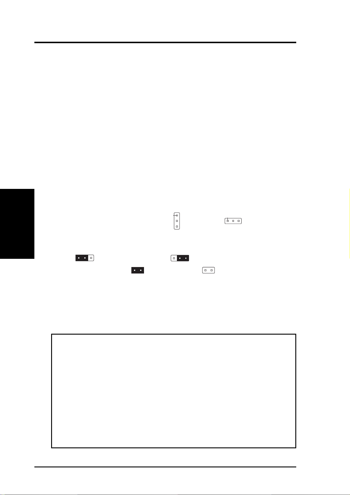
1. Jumpers
Several hardware settings are made through the use of jumper caps to connect jumper
pins (JP) on the baseboard. See “Baseboard Layout” on page 10 for locations of
jumpers. The jumper settings will be described numerically such as [----], [1-2],
(Jumpers)
[2-3] for no connection, connect pins 1&2, and connect pins 2&3 respectively. Pin
1 for our baseboards is usually on top
baseboard with the keyboard connector away from yourself. A “1” is written be-
sides pin 1 on jumpers with three pins. The jumpers will also be shown graphically
such as
two pins will be shown as for short (On) and for open (Off). For manufacturing simplicity, the jumpers may be sharing pins from other groups. Use the
diagrams in this manual instead of following the pin layout on the board. Settings
with two jumper numbers require that both jumpers be moved together . To connect
the pins, simply place a plastic jumper cap over the two pins as diagramed.
WARNING! Computer motherboards, baseboards and components, such as SCSI
cards, contain very delicate Integrated Circuit (IC) chips. To protect them against
damage from static electricity , you should follow some precautions whenever you
work on your computer.
to connect pins 1&2 and to connect pins 2&3. Jumpers with
Pin 1
or on the left
Pin 1
when holding the
1. Unplug your computer when working on the inside.
2. Use a grounded wrist strap before handling computer components. If you do
not have one, touch both of your hands to a safely grounded object or to a
metal object, such as the power supply case.
3. Hold components by the edges and try not to touch the IC chips, leads or
connectors, or other components.
4. Place components on a grounded antistatic pad or on the bag that came with
the component whenever the components are separated from the system.
12 ASUS P/I-P65UP8 User’s Manual
Page 13

III. INSTALLATION
Jumper Settings
1. i960 Bridge Setting
The secondary PCI slots can function as standard PCI slots when the i960 is set
to “Bridge” mode. When the i960 is set to “I2O” mode, the secondary PCI slots
are controlled by the i960 and only intelligent I/O (I2O) cards can be used on the
secondary PCI slots. Additional memory is required for the “I2O” mode.
960SEL Setting
I20 [1-2]
Bridge [2-3]
R
Caution! The jumper numbering is reversed
960SEL
3
2
1
I20
960SEL
3
2
1
Bridge
i960 Setting
2. i960 Local DRAM RAS Setting
When the i960 is set to I20, the i960 chip acts as a processor and at least one
SIMM memory module is required. When using a single memory module, this
jumper does not need setting. When using two memory modules, this jumper
needs to be set according to the number of sides used by the chips mounted on
the memory modules.
DRAMRAS Setting
Single Sided DRAM [1-2]
Double Sided DRAM [2-3]
(Jumpers)
III. INSTALLATION
R
DRAM RAS Setting
ASUS P/I-P65UP8 User’s Manual 13
DRAMRAS
1
2
3
Single Sided
DRAMS
DRAMRAS
1
2
3
Double Sided
DRAMS
Page 14

III. INSTALLATION
3. 7880 ID Setting
Set to SCSI ID 9, if you wish for the onboard Adpatec 7880 SCSI device to boot.
Set to SCSI ID 15, if you wish for the onboard Symbios 53C876 device to boot.
7880IDSEL Setting
ID 9-Boot [2-3]
ID 15-No boot [1-2]
R
III. INSTALLATION
(Jumpers)
7880 ID Setting
7880IDSEL
123
SCSI ID 9
7880IDSEL
123
SCSI ID 15
14 ASUS P/I-P65UP8 User’s Manual
Page 15

4. Real Time Clock (RTC) RAM (RTCLR)
This clears the user-entered information stored in the CMOS RAM of the Real
Time Clock such as hard disk information and passwords. To clear the RTC
data: (1) T urn off your computer and unplug the AC power, (2) Move this jumper
to Clear CMOS, (3) Power on the computer, (4) Power off the computer, (5)
Remove this jumper, (6) Power on the computer, (7) Hold down <Delete> during bootup and enter BIOS setup to re-enter user preferences.
Selections RTCLR
Operation [open] (Default)
Clear CMOS [short] (momentarily)
JP2
Battery
Test
R
RTCLR
Operation
Open (Default)
JP1
Battery Test (Remove jumper to test)
RTC RAM
Clear CMOS
Short
5. Battery Test Jumper (JP1, JP2)
You can test the battery’s current by removing the jumper and attaching a current meter to the two pins.
WARNING! You must unplug the power cord to your power supply to ensure
that there is no power to your baseboard. The CMOS RAM containing the BIOS
setup information may be cleared by this action. You must enter BIOS to “Load
Setup Defaults” and re-enter any user information after removing and reapplying this jumper.
(Jumpers)
III. INSTALLATION
ASUS P/I-P65UP8 User’s Manual 15
Page 16

III. INSTALLATION
(Jumpers)
III. INSTALLATION
6. CPU External (BUS) Frequency Selection (FS0, 1, 2) (Baseboard)
These jumpers tells the clock generator what frequency to send to the CPU.
These allow the selection of the CPU’ s External frequency (or BUS Clock). The
BUS Clock multiplied by the BUS Ratio equals the CPU’s Internal frequency
(the advertised CPU speed).
BUS Freq. FS2 FS1 FS0
50MHz [ON] [ON] [ON]
60MHz [----] [----] [ON]
66MHz [----] [----] [----]
R
FS0
FS1
FS2
FS1
FS0
FS2
FS2
FS1
FS0
50MHz 60MHz 66MHz
CPU External Clock (BUS) Frequency Setting
Jumper settings on CPU Card Settings on Baseboard
Intel Pentium Pro (P6) Processor: (Chipset Freq (CPU Ext. Freq
CPU BUS (CPU Card BUS Ratio) on CPU Card) Ext. on Baseboard)
Internal Ratio JP13 JP14 JP15 JP16 JP6 JP7 Freq. FS2 FS1 FS0
200MHz 3.0x [ON] [ON] [----] [ON] [ON] [----] 66MHz [----] [----] [----]
180MHz 3.0x [ON] [ON] [----] [ON] [----] [ON] 60MHz [----] [----] [ON]
166MHz 2.5x [ON] [----] [ON] [ON] [ON] [----] 66MHz [----] [----] [----]
150MHz 2.5x [ON] [----] [ON] [ON] [----] [ON] 60MHz [----] [----] [ON]
Intel Pentium II Processor: CPU Ext. Freq
CPU BUS (CPU Card BUS Ratio) Ext. on Baseboard)
Internal Ratio JP1 JP2 JP3 JP4 Freq. FS2 FS1 FS0
333MHz 5.0x [short] [open] [open] [short] 66MHz [----] [----] [----]
300MHz 4.5x [open] [short] [open] [short] 66MHz [----] [----] [----]
266MHz 4.0x [short] [short [open] [short] 66MHz [----] [----] [----]
233MHz 35x [open] [open] [short] [short] 66MHz [----] [----] [----]
16 ASUS P/I-P65UP8 User’s Manual
Page 17

III. INSTALLATION
(This page was intentionally left blank)
(Jumpers)
III. INSTALLATION
ASUS P/I-P65UP8 User’s Manual 17
Page 18

III. INSTALLATION
(Memory)
III. INSTALLATION
2. System Memory (DRAM)
This baseboard supports eight 72-pin SIMMs (Single Inline Memory Modules) of
4MB, 8MB, 16MB, 32MB, 64MB, 128MB to form a memory size between 8MB to
1GB. The DRAM can be either 60ns or 70ns Fast Page Mode (Asymmetric or
Symmetric), Extended Data Output (EDO), or Burst Extended Data Output (BEDO)
(with C-P6ND only). SIMMs must be installed in pairs so that each bank contains
two of the same size memory modules. To support ECC, you must use true (opposed to phantom parity generated by TTL chips) 36-bit parity-type SIMM (e.g. 8
chips + 4 parity chips) in pairs for all modules. Mixing 32-bit non-parity SIMM
(e.g. 8 chips) and 36-bit SIMM (e.g. 12 chips) will work minus the ECC feature.
IMPORTANT: Memory setup is required in “Auto Configuration” in the
CHIPSET FEATURES SETUP of the BIOS software. Each bank must have
the same size memory installed in pairs.
Install memory in any or all of the banks in any combination as follows:
Bank Memory Module Total Memory
Bank 0 4, 8, 16, 32, 64, 128MB x2
SIMM Slots 1&2 72-pin FPM, EDO, BEDO SIMM
Bank 1 4, 8, 16, 32, 64, 128MB x2
SIMM Slots 3&4 72-pin FPM, EDO, BEDO SIMM
Bank 2 4, 8, 16, 32, 64, 128MB x2
SIMM Slots 5&6 72-pin FPM, EDO, BEDO SIMM
Bank 3 4, 8, 16, 32, 64, 128MB x2
SIMM Slots 7&8 72-pin FPM, EDO, BEDO SIMM
Total System Memory (Max 1GB) =
NOTE: Memory on socket 1 has a clearance of 5.0 cm when the C-PKND and
C-P6ND CPU cards are installed and 5.5 cm when the C-P55T2D CPU card is installed.
IMPORT ANT : Each bank must have the same size memory installed in pairs. Do not
use memory modules with more than 24 chips per module. Modules with more than 24
chips exceed the design specifications of the memory subsystem and will be unstable.
i960 Local DRAM: The i960 requires 4MB to 256MB (16MB recommended)
memory using one or two EDO DRAM modules when 960SEL jumper is set to
“I2O.” The i960 does not requir e memory in the “Bridge” mode. Use i960 SIMM
socket 1 when using only one module. The i960 does not support parity or ECC.
18 ASUS P/I-P65UP8 User’s Manual
Page 19

III. INSTALLATION
DRAM Memory Installation Procedures
IMPORTANT: Install memory modules in symmetric pairs.
1. The SIMM memory modules will only fit in one orientation as shown because
of a “Plastic Safety Tab” on one end of the SIMM slots which requires the
“Notched End” of the SIMM memory modules.
R
Notched End
72 Pin SIMM Sockets
i960
Memory
5678123421
System Memory
2. Press the memory module firmly into place starting from a 45 degree angle
making sure that all the contacts are aligned with the slot.
3. With your finger tips, rock the memory module into a vertical position so that it
clicks into place.
Clip
Plastic Safety Tab (This Side Only)
72 Pin DRAM in SIMM Socket
Mounting Hole
4. The plastic guides should go through the two mounting holes on the sides and
the clips should snap on the other side.
(DRAM Memory)
III. INSTALLATION
5. To release the memory module, squeeze both clips outward and rock the module
out of the clips.
ASUS P/I-P65UP8 User’s Manual 19
Page 20

III. INSTALLATION
3. Central Processing Unit
The P/I-P65UP8 baseboard provides a CPU card slot that can be used with the ASUS
C-PKND or C-P6ND CPU cards, which are available separately. You must purchase
any one of these CPU cards (see next page for a brief description) to complete the
system’ s board.
System Case
The system case must be a full-size tower or server case to give a clearance as
follows:
2 3/4” (7.0 cm)
III. INSTALLATION
(CPU Card)
Pentium II Processor
Pentium II Heatsink
2 1/2” (6.4 cm)
ISA 2 Expansion Card
ISA 1 Expansion Card
System Cabinet Clearance Area Requirement for the P/I-P65UP8 + CPU Card
ISA 3 Expansion Card
PS/2
Mouse
PS/2
Keyboard
12.2” (30.7 cm)
PCI 2 Long Expansion Card
PCI 1 Long Expansion Card
PCI 3 Short Expansion Card
Secondary PCI 1 Short Card
5” (12.7 cm)
Secondary PCI 4 Long Card
Secondary PCI 3 Long Card
Secondary PCI 2 Long Card
NOTE: The C-P6ND Pentium Pro CPU card can easily fit in the given space, but
the C-PKND Pentium II CPU card will block the ISA 3 slot.
20 ASUS P/I-P65UP8 User’s Manual
Page 21

III. INSTALLATION
One end of the CPU card has a bracket, which should slide into the system case front
panel. Be sure that the system case can support a long PCI card on the first slot and
that a groove is available for the bracket. Refer to your respective CPU card’ s documentation for details.
General Installation Procedures for the ASUS CPU Card:
1. Remove the CPU card from its packaging without touching the integrated circuit
(IC) chips, connectors, and other components. Place it onto the antistatic bag.
2. Follow instructions in the CPU card manual on installing the processor/s, support bracket, and setting jumpers.
3. Remove the expansion slot cover for the first slot.
4. Carefully align the CPU card over the CPU Card Slot (CPU SLOT A and CPU
SLOT B).
5. Be sure that the card is perpendicular to the baseboard. Firmly press one end of
the card halfway in, the other end halfway in, then the first end completely in,
and finally, the second end completely in. Be sure that all the connectors are
evenly inserted into the slots.
6. Screw in the metal bracket to the system case.
WARNING! Move the system carefully and only with the power off because
the CPU card is heavy as well as delicate.
(CPU Card)
III. INSTALLATION
NOTE: The BIOS on the CPU cards are different. When adding a CPU card, find
the BIOS chip that came with the CPU card and replace it with the one on the baseboard, if one is present.
ASUS P/I-P65UP8 User’s Manual 21
Page 22

4. Expansion Cards
First read your expansion card documentation on any hardware and software settings that may be required to set up your specific card.
WARNING! Unplug your power supply when adding or removing expansion
cards or other system components. Failure to do so may cause severe damage to
both your baseboard and expansion cards.
Expansion Card Installation Procedure
1. Read the documentation for your expansion card.
2. Set any necessary jumpers on your expansion card.
3. Remove your computer system’s cover.
4. Remove the bracket on the slot you intend to use. Keep the bracket for possible
III. INSTALLATION
(Expansion Cards)
5. Carefully align the card’s connectors and press firmly.
6. Secure the card on the slot with the screw you removed in step 4.
7. Replace the computer system’s cover.
8. Set up the BIOS if necessary
9. Install the necessary software drivers for your expansion card.
III. INSTALLATION
future use.
(such as IRQ xx Used By ISA: Yes in PNP AND PCI SETUP)
Assigning IRQs for Expansion Cards
IMPORTANT: Interrupt requests are shared as shown by the following table:
INT-A INT-B INT-C INT-D
PCI slot 1 shared -- -- -PCI slot 2 -- shared -- -PCI slot 3 -- -- shared -Onboard VGA -- -- shared -7880 SCSI -- shared -- -i960 processor -- -- -- shared
2nd-PCI slot 1 -- -- -- shared
2nd-PCI slot 2 shared -- -- -2nd-PCI slot 3 -- -- -- -2nd-PCI slot 4 -- -- -- -Symbios SCSI shared ch.2 -- -- shared ch.1
If using PCI cards on shared slots, make sure that the drivers support “Share IRQ” or
that the cards do not need IRQ assignments. Conflicts will arise between the two
PCI groups that will make the system unstable or cards inoperable.
22 ASUS P/I-P65UP8 User’s Manual
Page 23

III. INSTALLATION
Some expansion cards need to use an IRQ to operate. Generally an IRQ must be
exclusively assigned to one use. In a standard design there are 16 IRQs available but
most of them are already in use, leaving 6 IRQs free for expansion cards.
Both ISA and PCI expansion cards may require to use IRQs. System IRQs are available to cards installed in the ISA expansion bus first, then any remaining IRQs are
available to PCI cards. Currently , there are two types of ISA cards. The original ISA
expansion card design, now referred to as legacy ISA cards, requires that you configure the card’ s jumpers manually and then install it in any available slot on the ISA
bus. You may use Microsoft Diagnostics (MSD.EXE) utility located in the Windows directory to see a map of your used and free IRQs. If you use W indows 95, the
Resources tab under Device Manager displays the resource settings being used by
a particular device (to gain access, double-click the System icon under the Control
Panel program). Ensure that no two devices share the same IRQs or your computer
will experience problems when those two devices are in use at the same time.
T o simplify this process, the baseboard complies with the Plug and Play (PnP) specification, which was developed to allow automatic system configuration whenever a
PnP-compliant card is added to the system. For PnP cards, IRQs are assigned automatically from those available.
If the system has both legacy and PnP ISA cards installed, IRQs are assigned to PnP
cards from those not used by legacy cards. The PCI and PNP configuration section
of the BIOS setup utility can be used to assign which IRQs are being used by legacy
cards. For older legacy cards that do not work with the BIOS, you may contact your
vendor for an ISA Configuration Utility.
An IRQ number is automatically assigned to PCI expansion cards after those used
by legacy and PnP ISA cards. In the PCI bus design, the BIOS automatically assigns
an IRQ to a PCI slot that contains a card requiring an IRQ. T o install a PCI card, you
need to set the INT (interrupt) assignment. Since all the PCI slots on this baseboard
use an INTA #, set the jumpers on your PCI cards to INT A.
Assigning DMA Channels for ISA Cards
Some ISA cards, both legacy and PnP, may also need to use a DMA (Direct Memory
Access) channel. DMA assignments for this baseboard are handled the same way as
the IRQ assignment process described earlier . You can select a DMA channel in the
PCI and PnP configuration section of the BIOS Setup utility.
(DMA Channels)
III. INSTALLATION
IMPORTANT: T o avoid conflicts, reserve the necessary IRQs and DMAs for legacy
ISA cards (under PNP AND PCI SETUP of the BIOS SOFTWARE, choose Yes in
IRQ xx Used By ISA and DMA x Used By ISA for those IRQs and DMAs you want to
reserve).
ASUS P/I-P65UP8 User’s Manual 23
Page 24

III. INSTALLATION
(Connectors)
III. INSTALLATION
5. External Connectors
WARNING! Some pins are used for connectors or power sources. These are
clearly differentiated from jumpers as shown in the baseboard layout on page
10. Placing jumper caps over these pins will cause damage to your baseboard.
IMPORTANT: Connect ribbon cables such that the red stripe is on the pin 1 side of
the connector. The four corners of the connectors are labeled on the baseboard. Pin
1 is the side closest to the power connector on hard and floppy disk drives. IDE
ribbon cable must be less than 18in. (46cm), with the second drive connector no
more than 6in. (15cm) from the first connector.
1. Keyboard Connector (5-pin KBCON)
This connector is for either a standard IBM-compatible, 101/102-key, or 104key (Windows 95-compatible) keyboard. Use either the A T keyboard connector
on the baseboard or PS/2 keyboard connector on the CPU card.
PS/2 Mouse
R
Keyboard Connector
Keyboard Connector
(5-pin female)
Connector Plug
from Keyboard
Port (CPU Card)
PS/2 Keyboard
Port (CPU Card)
2. Floppy Disk Drive Connector (34-1 pin FLOPPY)
This connector supports the provided floppy drive ribbon cable. After connecting the single end to the board, connect the two plugs on the other end to the
floppy drives. (Pin 5 is removed to prevent inserting in the wrong orienta-
tion when using ribbon cables with pin 5 plugged).
Pin 1
R
Orient the red stripe on the
floppy ribbon cable to Pin 1
Floppy Disk Drive Connector
24 ASUS P/I-P65UP8 User’s Manual
Page 25

III. INSTALLATION
3. Parallel Printer Connector (26-1 pin PRINTER)
This connector supports the included parallel port ribbon cable with mounting
bracket. Connect the ribbon cable to this connector and mount the bracket to the
case on an open slot. You can make available the parallel port and choose the
IRQ Onboard Parallel Port in Chipset Features of the BIOS SOFTWARE.
(Pin 26 is removed to prevent inserting in the wr ong orientation when using
ribbon cables with pin 26 plugged)
R
Pin 1
Orient the red stripe on the
parallel ribbon cable to Pin 1
For the parallel port connector to be available,
connect the included parallel (25-pin female)
cable set to a free expansion port.
TIP: You may also remove the bracket
connectors and mount them directly to
the case to save expansion slot space.
Parallel Port Connector
4. Serial Port COM1 and COM2 Connectors (Two 10-1 pin COM1 & COM2)
These connectors support the provided serial port ribbon cables with mounting
bracket. Connect the ribbon cables to these connectors and mount the bracket to
the case on an open slot. You can make available the serial port and choose the
IRQ Onboard Serial Port in Chipset Features of the BIOS SOFTWARE. (Pin
10 is removed to prevent inserting in the wrong orientation when using
ribbon cables with pin 10 plugged)
(Connectors)
III. INSTALLATION
R
Serial Port Connectors
ASUS P/I-P65UP8 User’s Manual 25
Pin 1
Pin 1
COM 2
COM 1
Orient the red stripe on the
serial ribbon cable to Pin 1
For the serial port connectors to be available,
connect the included serial cable set from
COM1 (using 9-pin male) and COM2 (using
25-pin male) to a free expansion port.
TIP: You may also remove the bracket
connectors and mount them directly to
the case to save expansion slot space.
Page 26

III. INSTALLATION
(Connectors)
III. INSTALLATION
5. Primary/Secondary IDE Connectors (Two 40-1 pin IDE1 & IDE2)
These connectors support the provided IDE hard disk ribbon cable.
After connecting the single end to the board, connect the two plugs at the other
end to your hard disk(s). If you install two hard disks on one connector (channel), then you must configure a second drive as Slave mode by setting its jumper
according to your hard disk jumper diagram. You may also configure two hard
disks to be both Masters using one ribbon cable on the primary IDE connector
and another on the secondary IDE connector . A new BIOS feature allows SCSI
hard drive bootup (see “HDD Sequence SCSI/IDE First” in the BIOS FEATURES SETUP of the BIOS software). (Pin 20 is r emoved to pr event insert-
ing in the wrong orientation when using ribbon cables with pin 20 plugged).
Pin 1
Orient the red stripe on the
IDE ribbon cable to Pin 1
R
Secondary IDE Connector
Primary IDE Connector
IDE (Hard Disk Drive) Connectors
6. SCSI and IDE Activity LED (2-pin HD LED)
This connector connects to the hard disk activity indicator light on the system
cabinet. Read and write activity by devices connected to the Primary or Secondary IDE connectors will cause the HD LED to light.
R
IDE Activity LED Lead
TIP: If the case-mounted LED does
not light, try reversing the 2-pin plug.
HD LED A (for Symbios Ch A)
+
+
+
HD LED B (for Symbios Ch B)
HD LED (for Adaptec and IDE)
26 ASUS P/I-P65UP8 User’s Manual
Page 27

III. INSTALLATION
7. VGA Connector (16 pin VGACON)
To use the onboard VGA, you must attach the provided VGA cable to this connector and mount the bracket to the system cabinet on a free expansion slot or
remove the bracket and mount to the system cabinet’s serial port opening. The
VGA cable then provides a standard 15-pin D-Sub connector for a monitor.
1
R
15
TIP: You may also remove the bracket
connectors and mount them directly to
the case to save expansion slot space.
Orient the red stripe on the
2
monitor cable with pin 1
16
Bracket to end approximately 6inch
VGA (Monitor) Connector
8. VGA Memory Upgrade Sockets
This baseboard comes with 1MB VGA memory. Two sockets are provided to
upgrade the VGA memory to 2MB by adding two EDO DRAM’s.
Socket's cut corner
R
Small indentation on
the chip’s sloped edge
(Connectors)
III. INSTALLATION
Each chip is 512KB DRAM. Two chips must be
installed to increase the VGA memory by 1MB.
VGA Memory Sockets
NOTE: The indentations are shown white for visibility, they are normally black.
Match the small indentation on the chip’ s sloped edge with the socket’ s cut corner .
Place the chip flat and evenly into the socket and press firmly but carefully so that
the chip enters evenly. When installed, the chip should be flush with the socket.
ASUS P/I-P65UP8 User’s Manual 27
Page 28

III. INSTALLATION
9. IrDA-compliant Infrared Module Connector (5-pin IR)
This connector supports the optional wireless transmitting and receiving infrared module. This module mounts to a small opening on system cases that support this feature. You must also configure the setting through BIOS setup in
Chipset Features to select whether UART2 is directed for use with COM2 or
IrDA. Use the five pins (as defined by Intel) as shown below (Back View) and
connect a ribbon cable from the module to the baseboard according to the pin
definitions. The ribbon cable that may be supplied may either have five or ten
pins (for other standards). If using a ten-pin ribbon cable, use only the top five
row of the ribbon cable plug.
For the infrared feature to be available, connect an
infrared module (optional) to the baseboard.
III. INSTALLATION
(Connectors)
R
NC
GND
+5V
IRRX
IRTX
Back ViewFront View
IRTX
GND
+5V
NC
IRRX
Infrared Module Connector
10. USB Module Connector (10-1 pin USB)
If you want to use the universal serial bus (USB), you need to purchase an external connector set. The external connector connects to the 9-pin block.
1
2
910
R
1: USB +5Volt
3: USB Port 1 –
5: USB Port 1 +
7: Ground
9: (no connection)
2: USB +5Volt
4: USB Port 0 –
6: USB Port 0 +
8: Ground
10: (no connection)
USB Module Connector
28 ASUS P/I-P65UP8 User’s Manual
Page 29

III. INSTALLATION
11. ASUS System Monitoring Module Connector (20-1 pin SERVER_CON)
This connector is for an optional ASUS System Monitoring Module for monitoring system temperature and fan RPM.
R
Pin 1
Server Connector
12. Chassis Open Alarm Connector (4-1 pin CHASSIS)
This connector is for an optional ASUS System Monitoring Module for monitoring chassis open/close status. A high level signal to the chassis signal lead
will indicate to the system that the chassis has been opened.
R
Chassis Connector
Power (+3V/+5V)
Chassis Signal
Ground
For the chassis open alarm feature to work, you must connect
the optional ASUS Server Managment Module to these pins.
The +5V power comes from the power supply, when the A/C
is connected. With the A/C power disconnected, the +3V power
comes from the onboard button cell battery.
(Connectors)
III. INSTALLATION
ASUS P/I-P65UP8 User’s Manual 29
Page 30

III. INSTALLATION
(Connectors)
III. INSTALLATION
13. SMI Suspend Switch Lead (SMI)
This allows the user to manually place the system into a suspend mode or “Green”
mode where system activity will be instantly decreased to save electricity and
expand the life of certain components when the system is not in use. This 2-pin
connector (see the figure below) connects to the case-mounted suspend switch.
If you do not have a switch for the connector , you may use the “Turbo Switch”
since it does not have a function. SMI is activated when it detects a short to
open moment and therefore leaving it shorted will not cause any problems. May
require one or two pushes depending on the position of the switch. W ake-up can
be controlled by settings in the BIOS but the keyboard will always allow wakeup (the SMI lead cannot wake-up the system). If you want to use this connector ,
“Suspend Switch” in the Power Management Setup of the BIOS SOFTWARE
section should be on the default setting of Enable.
14. ATX Power Switch / Soft Power Switch (PWR SW.) (ATX Power Req.)
The system power can be controlled by a momentary switch connected to this
lead. Pushing the button once will switch the system between ON and OFF.
The system power LED shows the status of the system’s power.
15. Reset Switch Lead (RESET)
This 2-pin connector connects to the case-mounted reset switch for rebooting
your computer without having to turn off your power switch This is a preferred
method of rebooting in order to prolong the life of the system’s power supply.
16. System Power LED (PWR.LED) or (TB.LED)
This 3-pin (PWR.LED) or 2-pin (TB.LED) connector connects to the system
power LED, which lights when the system is powered on and blinks when it is in
sleep (suspend) mode.
17. Keyboard Lock Switch Lead (KEYLOCK)
This 2-pin connector connects to the case-mounted key switch to allow keyboard locking.
18. Speaker Connector (SPEAKER)
This 4-pin connector connects to the case-mounted speaker.
R
Power LED
SMI Lead
ATX Power
Switch*
Reset SW
*
Requires an ATX power supply.
+5 Volts
Ground
ExtSMI#
Ground
PWRBT#
Ground
ResetCon
Ground
+5 Volts
PLED#
KLock#
Ground
+5 Volts
Ground
Ground
SPKR
Power LED
Keyboard Lock
Speaker
Connector
System Panel Connectors
30 ASUS P/I-P65UP8 User’s Manual
Page 31

III. INSTALLATION
19. Ultra-Fast SCSI & Ultra-Wide SCSI Connectors
This motherboard provides three onboard 50-Pin Ultra-Fast SCSI connector for
8-bit SCSI devices and three 68-Pin Ultra-Wide SCSI connector for 16-bit SCSI
devices.
R
68-pin Fast/Wide
SCSI Connector
50-pin Fast/Narrow
SCSI Connector
Onboard SCSI Connectors
Ultra-Fast SCSI & Ultra-Wide SCSI Connection Example
Up to 15 devices can be connected on each channel using either 50-Pin FastSCSI and/or 68-Pin Ultra-Wide SCSI connections. Three channels are provided
on this motherboard.
50-pin SCSI
device
SCSI devices“in-between”
must not be terminated
68-pin SCSI
device
50-pin SCSI
device
68-pin SCSI
device
50-pin SCSI
device (end)
Last SCSI device
on the SCSI cable
must be terminated
68-pin SCSI
device (end)
(Connectors)
III. INSTALLATION
SCSI device connection on one channel (two types of connectors are provided).
Connect one chain of 50-pin SCSI devices and/or one chain of 68-pin SCSI device
not to exceed a maximum of 15 SCSI devices on each channel.
ASUS P/I-P65UP8 User’s Manual 31
Page 32

III. INSTALLATION
20. Main and Auxilliary AT Power Connectors (12-pin & 6-pin PWRCON)
This connector connects to a standard 5 Volt power supply . To connect the leads
from the power supply, ensure first that the power supply is not plugged. Most
power supplies provide two plugs (P8 and P9), each containing six wires, two of
which are black. An auxilliary connector (P10) is provided in case the power
supplied through the main connectors are insufficient. Orient the main connectors so that the black wires are located in the middle.
III. INSTALLATION
(Connectors)
R
AT Power Connector
+5Volts
-12Volts
-5Volts
PG
+12Volts
Ground
+5Volts
+5Volts
Ground
Power Connector
on Motherboard
P8
P9
P10
Power Plugs from
Power Supply
ORG
RED
YLW
BLU
BLK
BLK
BLK
BLK
WHT
RED
RED
RED
RED
RED
RED
BLK
BLK
BLK
Using a slight angle, align the plastic guide pins on the lead to their receptacles
on the connector . Once aligned, press the lead onto the connector until the lead
locks into place.
21. ATX Power Supply Connector (20-pin ATXPWR)
This connector connects to a ATX power supply. The plug from the power
supply will only insert in one orientation because of the different hole sizes.
Find the proper orientation and push down firmly making sure that the pins are
aligned.
IMPORT ANT : Be sur e that the A TX power supply can take at least 10mAmp
load on the 5volt standby lead (5VSB). You may experience difficulty in
powering on your system without this.
+5.0 Volts
+5.0 Volts
-5.0 Volts
Ground
Ground
Ground
Power Supply On
Ground
-12.0 Volts
+3.3 Volts
R
ATX Power Connector
+12.0 Volts
+5V Standby
Power Good
Ground
5.0 Volts
Ground
+5.0 Volts
Ground
+3.3 Volts
+3.3 Volts
Power Connector
on Motherboard
32 ASUS P/I-P65UP8 User’s Manual
Page 33

IV. VGA Installation
Windows 95 Video Driver Installation
Installing Video drivers in Windows 95 (New Hardware Found)
If you are installing the S3 T rio64 graphics device for W indows 95 for the first time,
a New Hardware Found window will appear:
1. Click OK to use the default selection: Driver from disk provided by hard-
ware manufacturer
2. Insert ASUS support CD and click Browse button - Open window appears
3. Select your CD-ROM drive in the Drives: box
4. Select VGA\WIN95
5. Click the OK button - Install from Disk appears - Click OK button again
6. After restarting Windows, your S3 Trio64 graphics device should be automatically detected.
(Windows 95)
IV. VGA Installation
ASUS P/I-P65UP8 User’s Manual 33
Page 34

Windows 95 Video Driver Installation
Using Control Panel
1. Start Windows 95, switch display to VGA mode, then restart.
2. Press right key of mouse on your desktop and select Properties. Click the Set-
IV. VGA Installation
(Windows 95)
IV. VGA Installation
tings tab.
3. Select Change Display Type.
4. Click Change..
5. Click Have Disk. Insert the ASUS support CD. Type D:\VGA\WIN95 (as-
suming your CD-ROM drive is letter D) or click Browse button to select the
path of the display driver for Windows 95. Click OK. You will see a list of
ASUS VGA devices. Select the appropriate VGA device and press OK to start
installation.
6. When all files are copied, return to Display Properties window by clicking
Close. Press Apply.. Click Yes to restart Windows.
7. When Windows starts up, your VGA device is now ready to use.
34 ASUS P/I-P65UP8 User’s Manual
Page 35

IV. VGA Installation
Windows 95 Display Settings
Changing display settings
To enter the Display Properties at any time, right click your mouse on the desktop
and select Properties or double click the Display icon in the Control Panel. Click
the appropriate Tab as follows:
Adjustment:
Lets you change your monitor settings, such as position, size, refresh rate and performance.
Adjust
display position
Adjust
display size
Change Refresh Rate:
List of refresh
rate options
Customize
refresh rate
Add to list
Current virtual desktop screen and color
Change refresh rate
Adjust performance
Set to default values
Set to default supported refresh rate
(Windows 95)
IV. VGA Installation
Delete
from list
Test customized
refresh rates
ASUS P/I-P65UP8 User’s Manual 35
Page 36

IV. VGA Installation
Adjust Performance
Hotkey:
Allows you to assign hotkeys in the "Value" box to move your screen up, down, left,
and right, or zoom in, zoom out in virtual desktop.
IV. VGA Installation
(Windows 95)
Lowest
performance
List of hotkey
options
Highest
performance
Value
Description
Hotkey enabled
Set to default
hotkey values
Settings:
Allows you to change your display settings, adjust screen resolution and color depth,
virtual desktop, color palette and font size.
Current
refresh rate
Adjust color
Adjust font size
Adjust
screen resolution
Adjust virtual
desktop size
36 ASUS P/I-P65UP8 User’s Manual
Page 37

IV. VGA Installation
Windows NT 4.0 Video Driver Installation
1. Boot Windows NT in standard VGA mode (recommended).
2. Run Windows NT Display program located in the Control Panel, under Set-
tings in the Start menu. Alternatively , position the cursor on the background of
the desktop, click the right mouse button, then select Properties from the popup
menu.
3. Select the Settings page.
4. Select Display Type...
5. Select Change... from the display options.
6. Select Have Disk...
7. Windows NT will prompt you for the correct path, enter the path of driver in
CD-ROM such as D:\VGA\NT40 (assuming your CD-ROM drive is letter D).
8. A list of ASUS S3 series video adapters will be displayed. Select the one you
are using, then click on the OK button.
9. Windows NT will once again prompt for confirmation. All appropriate files are
then copied to the hard disk.
10. Select Apply in Control Panel. Restart W indows NT. Windows NT will start
up using the S3 drivers.
11. Windows NT will boot into a default mode and start the Display applet allowing
for mode selection.
(Windows NT 4.0)
IV. VGA Installation
ASUS P/I-P65UP8 User’s Manual 37
Page 38

Windows NT 3.51 Video Driver Installation
1. Boot Windows NT in standard VGA mode (recommended).
2. Double-click the Main icon.
3. Double-click the Control Panel icon.
4. Double-click the Display icon.
5. Click Change Display Type button.
6. Click Change button.
7. Click Other.
8. Insert the ASUS support CD into your CD-ROM drive. For W indows NT 3.51,
type the following: D:\VGA\NT351 (assuming your CD-ROM drive is letter D)
9. Click OK button.
IV. VGA Installation
(Windows NT 3.51)
10. Select S3 driver.
IV. VGA Installation
11. Click Install.
12. Click Yes to change your system configuration.
13. Click Continue to confirm the full path name.
14. After the files have been copied to your computer, click OK.
15. Reboot Windows NT .
16. After reboot, the Invalid Display Settings window appears. Click OK.
17. The Display Settings dialogue box appears. Select a desired display mode. For
more detailed information about changing your display mode, click Help.
38 ASUS P/I-P65UP8 User’s Manual
Page 39

IV. VGA Installation
IBM OS/2 Video Driver Installation
WARNING: The S3 Trio64 device OS/2 video driver is to be used for the
English version of OS/2 only.
1. Start OS/2 using standard VGA driver
2. Double-click the OS/2 System folder
3. Double-click the Command Prompts folder
4. Double-click the OS/2 Full Screen object
5. Insert the ASUS support CD (assuming your CD-ROM drive is letter D)
6. Type D:\VGA\OS2\ENGLISH <Enter> and SETUP.CMD <Enter>
7. In the Monitor Configuration Selection Utility, select Install Using Defaults
for Monitor Type
8. Click OK when Display Driver Install panel appears
9. Restart OS/2. It will default to 640x480 in 256 colors. T o change screen resolu-
tion and/or color depth, see your OS/2 User’s Guide.
AutoCAD Video Driver Installation
1. Enter DOS mode
2. Insert the ASUS support CD (assuming your CD-ROM drive is letter D)
3. Change current directory to D:\DOS\AutoCAD, type INSTALL <Enter>
4. Follow the instructions to complete the installation of the drivers. Type directory name where AutoCAD drivers are located when installation program asks
you. Your video drivers should be installed and ready to use.
Microstation Video Driver Installation
1. Enter DOS mode
2. Insert the ASUS support CD (assuming your CD-ROM drive is letter D)
3. Change current directory to D:\DOS\Mstation, type INSTALL <Enter>
4. Follow the instructions to complete the installation of the drivers. Your video
drivers should be installed and ready to use.
(OS/2,CAD, Micro.)
IV. VGA Installation
ASUS P/I-P65UP8 User’s Manual 39
Page 40

IV. VGA Installation
(This page was intentionally left blank)
40 ASUS P/I-P65UP8 User’s Manual
 Loading...