

Page 1

P5W
Motherboard
Page 2

E3500
First Edition V1
October 2007
Copyright © 2007 ASUSTeK COMPUTER INC. All Rights Reserved.
No part of this manual, including the products and software described in it, may be reproduced,
transmitted, transcribed, stored in a retrieval system, or translated into any language in any form or by any
means, except documentation kept by the purchaser for backup purposes, without the express written
permission of ASUSTeK COMPUTER INC. (“ASUS”).
Product warranty or service will not be extended if: (1) the product is repaired, modied or altered, unless
such repair, modication of alteration is authorized in writing by ASUS; or (2) the serial number of the
product is defaced or missing.
ASUS PROVIDES THIS MANUAL “AS IS” WITHOUT WARRANTY OF ANY KIND, EITHER EXPRESS
OR IMPLIED, INCLUDING BUT NOT LIMITED TO THE IMPLIED WARRANTIES OR CONDITIONS OF
MERCHANTABILITY OR FITNESS FOR A PARTICULAR PURPOSE. IN NO EVENT SHALL ASUS, ITS
DIRECTORS, OFFICERS, EMPLOYEES OR AGENTS BE LIABLE FOR ANY INDIRECT, SPECIAL,
INCIDENTAL, OR CONSEQUENTIAL DAMAGES (INCLUDING DAMAGES FOR LOSS OF PROFITS,
LOSS OF BUSINESS, LOSS OF USE OR DATA, INTERRUPTION OF BUSINESS AND THE LIKE),
EVEN IF ASUS HAS BEEN ADVISED OF THE POSSIBILITY OF SUCH DAMAGES ARISING FROM ANY
DEFECT OR ERROR IN THIS MANUAL OR PRODUCT.
SPECIFICATIONS AND INFORMATION CONTAINED IN THIS MANUAL ARE FURNISHED FOR
INFORMATIONAL USE ONLY, AND ARE SUBJECT TO CHANGE AT ANY TIME WITHOUT NOTICE,
AND SHOULD NOT BE CONSTRUED AS A COMMITMENT BY ASUS. ASUS ASSUMES NO
RESPONSIBILITY OR LIABILITY FOR ANY ERRORS OR INACCURACIES THAT MAY APPEAR IN THIS
MANUAL, INCLUDING THE PRODUCTS AND SOFTWARE DESCRIBED IN IT.
Products and corporate names appearing in this manual may or may not be registered trademarks or
copyrights of their respective companies, and are used only for identication or explanation and to the
owners’ benet, without intent to infringe.
ii
Page 3

Contents
Contents ...................................................................................................... iii
Notices ........................................................................................................ vii
Safety information .................................................................................... viii
About this guide ......................................................................................... ix
P5W specications summary .................................................................... xi
Chapter 1: Product introduction
1.1 Welcome! ...................................................................................... 1-1
1.2 Package contents .........................................................................
1.3 Special features ............................................................................
1.3.1 Product highlights ...........................................................
1.3.2 ASUS AI Life features ...................................................
1.3.3 Innovative ASUS features ..............................................
Chapter 2: Hardware information
2.1 Before you proceed ..................................................................... 2-1
2.2 Motherboard overview .................................................................
2.2.1 Placement direction ........................................................
2.2.2 Screw holes ....................................................................
2.2.3 ASUS Stack Cool 2 .........................................................
2.2.4 Motherboard layout .........................................................
2.2.5 Layout contents ...............................................................
2.3 Central Processing Unit (CPU) ...................................................
2.3.1 Installing the CPU ...........................................................
2.3.2 Installing the CPU heatsink and fan ..............................
2.3.3 Uninstalling the CPU heatsink and fan .........................
2.4 System memory .........................................................................
2.4.1 Overview .......................................................................
2.4.2 Memory congurations ..................................................
2.4.3 Installing a DIMM ..........................................................
2.4.4 Removing a DIMM ........................................................
2.5 Expansion slots ..........................................................................
2.5.1 Installing an expansion card .........................................
2.5.2 Conguring an expansion card .....................................
2.5.3 Interrupt assignments ...................................................
1-1
1-2
1-2
1-6
1-6
2-2
2-2
2-2
2-3
2-4
2-5
2-7
2-8
2-10
2-12
2-14
2-14
2-14
2-21
2-21
2-22
2-22
2-22
2-23
iii
Page 4

Contents
2.5.4 PCI slots ........................................................................ 2-24
2.5.5 PCI Express x1 slot .......................................................
2.5.6 Two PCI Express x16 slots ...........................................
2.6 Jumpers ......................................................................................
2.7 Connectors .................................................................................
2.7.1 Rear panel connectors ..................................................
2.7.2 Internal connectors .......................................................
Chapter 3: Powering up
3.1 Starting up for the rst time ........................................................ 3-1
3.2 Turning off the computer .............................................................
3.2.1 Using the OS shut down function ....................................
3.2.2 Using the dual function power switch ..............................
Chapter 4: BIOS setup
4.1 Managing and updating your BIOS ............................................ 4-1
4.1.1 ASUS Update utility ........................................................
4.1.2 Creating a bootable oppy disk .......................................
4.1.3 ASUS EZ Flash 2 utility ...................................................
4.1.4 AFUDOS utility ................................................................
4.1.5 ASUS CrashFree BIOS 3 utility ......................................
4.2 BIOS setup program ..................................................................
4.2.1 BIOS menu screen .........................................................
4.2.2 Menu bar ........................................................................
4.2.3 Navigation keys ..............................................................
4.2.4 Menu items ...................................................................
4.2.5 Sub-menu items ............................................................
4.2.6 Conguration elds .......................................................
4.2.7 Pop-up window .............................................................
4.2.8 Scroll bar .......................................................................
4.2.9 General help .................................................................
4.3 Main menu ..................................................................................
4.3.1 System Time [xx:xx:xx] .................................................
4.3.2 System Date [Day xx/xx/xxxx] .......................................
4.3.3 Legacy Diskette A [1.44M, 3.5 in.] .................................
4.3.4 Language [English] .......................................................
4.3.5 Primary, Third, and Fourth IDE Master/Slave ...............
2-24
2-24
2-26
2-28
2-28
2-31
3-2
3-2
3-2
4-1
4-4
4-5
4-6
4-9
4-10
4-11
4-11
4-11
4-12
4-12
4-12
4-12
4-12
4-12
4-13
4-13
4-13
4-13
4-13
4-14
iv
Page 5

Contents
4.3.6 IDE Conguration .......................................................... 4-15
4.3.7 System Information .......................................................
4.4 Advanced menu .........................................................................
4.4.1 JumperFree Conguration ............................................
4.4.2 LAN Cable Status .........................................................
4.4.3 USB Conguration ........................................................
4.4.4 CPU Conguration ........................................................
4.4.5 Chipset ..........................................................................
4.4.6 Onboard Devices Conguration ....................................
4.4.7 PCI PnP ........................................................................
4.5 Power menu ................................................................................
4.5.1 Suspend Mode [Auto] ...................................................
4.5.2 Repost Video on S3 Resume [No] ................................
4.5.3 ACPI 2.0 Support [No] ..................................................
4.5.4 ACPI APIC Support [Enabled] .......................................
4.5.5 APM Conguration ........................................................
4.5.6 Hardware Monitor .........................................................
4.6 Boot menu ..................................................................................
4.6.1 Boot Device Priority ......................................................
4.6.2 Hard Disk Drives ...........................................................
4.6.3 Boot Settings Conguration ..........................................
4.6.4 Security .........................................................................
4.7 Tools menu .................................................................................
4.7.1 ASUS Music Alarm ........................................................
4.7.2 ASUS EZ Flash 2 ..........................................................
4.8 Exit menu ....................................................................................
4-17
4-18
4-18
4-22
4-23
4-24
4-26
4-28
4-30
4-32
4-32
4-32
4-32
4-32
4-33
4-35
4-38
4-38
4-39
4-39
4-41
4-43
4-43
4-45
4-46
Chapter 4: Software support
5.1 Installing an operating system ................................................... 5-1
5.2 Support CD information ..............................................................
5.2.1 Running the support CD .................................................
5.2.2 Drivers menu ...................................................................
5.2.3 Utilities menu ..................................................................
5.2.4 Make Disk menu .............................................................
5.2.5 Manual menu ..................................................................
5.2.6 Contact information .........................................................
5-1
5-1
5-2
5-3
5-6
5-7
5-7
v
Page 6

Contents
5.2.7 Other information ............................................................ 5-8
5.3 Software information .................................................................
5.3.1 ASUS MyLogo 2 ...........................................................
5.3.2 AI NET2 ........................................................................
Using the Virtual Cable Tester™ .................................................. 5-12
5.3.3 Audio congurations .....................................................
5.3.4 ASUS PC Probe II .........................................................
5.3.5 ASUS Music Alarm ........................................................
5.4 RAID congurations ..................................................................
5.4.1 Installing Serial ATA hard disks .....................................
®
5.4.2 Intel
5.4.3 JMicron
5.4.4 Silicon Image
5.4.5 Cross-RAID Conguration ............................................
5.5 Creating a RAID driver disk .......................................................
5.5.1 Creating a RAID driver disk without entering the OS ....
5.5.2 Creating a RAID driver disk in Windows® ....................
Chapter 6: ATI® CrossFire™ technology support
6.1 Overview ....................................................................................... 6-1
6.1.1 Requirements ..................................................................
6.1.2 Before you begin .............................................................
6.2 Installing CrossFire™ graphics cards .......................................
6.3 Software information ...................................................................
6.3.1 Installing the device drivers .............................................
6.3.2 Using the Catalyst™ Control Center ...............................
RAID congurations ............................................. 5-30
®
RAID Conguration ........................................ 5-40
®
RAID conguration ................................ 5-48
5-10
5-10
5-12
5-13
5-20
5-26
5-29
5-30
5-61
5-64
5-64
5-64
6-1
6-1
6-2
6-5
6-5
6-7
Appendix: CPU features
A.1 Intel® EM64T ..................................................................................A-1
Using the Intel® EM64T feature ......................................................A-1
®
A.2 Enhanced Intel SpeedStep
A.2.1 System requirements ......................................................
A.2.2 Using the EIST ................................................................
®
A.3 Intel
Hyper-Threading Technology ...........................................A-3
Using the Hyper-Threading Technology ........................................ A-3
vi
Technology (EIST) ........................A-1
A-1
A-2
Page 7

Notices
Federal Communications Commission Statement
This device complies with Part 15 of the FCC Rules. Operation is subject to the
following two conditions:
•
This device may not cause harmful interference, and
•
This device must accept any interference received including interference that
may cause undesired operation.
This equipment has been tested and found to comply with the limits for a
Class B digital device, pursuant to Part 15 of the FCC Rules. These limits are
designed to provide reasonable protection against harmful interference in a
residential installation. This equipment generates, uses and can radiate radio
frequency energy and, if not installed and used in accordance with manufacturer’s
instructions, may cause harmful interference to radio communications. However,
there is no guarantee that interference will not occur in a particular installation. If
this equipment does cause harmful interference to radio or television reception,
which can be determined by turning the equipment off and on, the user is
encouraged to try to correct the interference by one or more of the following
measures:
•
Reorient or relocate the receiving antenna.
•
Increase the separation between the equipment and receiver.
•
Connect the equipment to an outlet on a circuit different from that to which the
receiver is connected.
•
Consult the dealer or an experienced radio/TV technician for help.
The use of shielded cables for connection of the monitor to the graphics card is
required to assure compliance with FCC regulations. Changes or modications
to this unit not expressly approved by the party responsible for compliance
could void the user’s authority to operate this equipment.
Canadian Department of Communications Statement
This digital apparatus does not exceed the Class B limits for radio noise emissions
from digital apparatus set out in the Radio Interference Regulations of the
Canadian Department of Communications.
This class B digital apparatus complies with Canadian ICES-003.
vii
Page 8

Safety information
Electrical safety
•
To prevent electrical shock hazard, disconnect the power cable from the
electrical outlet before relocating the system.
•
When adding or removing devices to or from the system, ensure that the
power cables for the devices are unplugged before the signal cables are
connected. If possible, disconnect all power cables from the existing system
before you add a device.
•
Before connecting or removing signal cables from the motherboard, ensure
that all power cables are unplugged.
•
Seek professional assistance before using an adpater or extension cord.
These devices could interrupt the grounding circuit.
•
Make sure that your power supply is set to the correct voltage in your area.
If you are not sure about the voltage of the electrical outlet you are using,
contact your local power company.
•
If the power supply is broken, do not try to x it by yourself. Contact a
qualied service technician or your retailer.
Operation safety
•
Before installing the motherboard and adding devices on it, carefully read all
the manuals that came with the package.
•
Before using the product, make sure all cables are correctly connected and the
power cables are not damaged. If you detect any damage, contact your dealer
immediately.
•
To avoid short circuits, keep paper clips, screws, and staples away from
connectors, slots, sockets and circuitry.
•
Avoid dust, humidity, and temperature extremes. Do not place the product in
any area where it may become wet.
•
Place the product on a stable surface.
•
If you encounter technical problems with the product, contact a qualied
service technician or your retailer.
viii
This symbol of the crossed out wheeled bin indicates that the product (electrical
and electronic equipment) should not be placed in municipal waste. Check local
regulations for disposal of electronic products.
Page 9

About this guide
This user guide contains the information you need when installing and conguring
the motherboard.
How this guide is organized
This guide contains the following parts:
• Chapter 1: Product introduction
This chapter describes the features of the motherboard and the new
technology it supports.
• Chapter 2: Hardware information
This chapter lists the hardware setup procedures that you have to perform
when installing system components. It includes description of the switches,
jumpers, and connectors on the motherboard.
• Chapter 3: Powering up
This chapter describes the power up sequence and ways of shutting down
the system.
• Chapter 4: BIOS setup
This chapter tells how to change system settings through the BIOS Setup
menus. Descriptions of the BIOS items are also provided.
• Chapter 5: Software support
This chapter describes the contents of the support CD that comes with the
motherboard package.
• Chapter 6: ATI CrossFire™ support
This chapter describes the ATI CrossFire™ feature and shows the graphics
card installation procedures.
• Appendix: CPU features
The Appendix describes the CPU features and technologies that the
motherboard supports.
Where to nd more information
Refer to the following sources for additional information and for product and
software updates.
1. ASUS websites
The ASUS website provides updated information on ASUS hardware and
software products. Refer to the ASUS contact information.
2. Optional documentation
Your product package may include optional documentation, such as warranty
yers, that may have been added by your dealer. These documents are not
part of the standard package.
ix
Page 10

Conventions used in this guide
To make sure that you perform certain tasks properly, take note of the following
symbols used throughout this manual.
DANGER/WARNING: Information to prevent injury to yourself
when trying to complete a task.
CAUTION: Information to prevent damage to the components
when trying to complete a task.
IMPORTANT: Instructions that you MUST follow to complete a
task.
NOTE: Tips and additional information to help you complete a
task.
Typography
Bold text Indicates a menu or an item to select.
Italics
Used to emphasize a word or a phrase.
<Key> Keys enclosed in the less-than and greater-than sign
means that you must press the enclosed key.
Example: <Enter> means that you must press the
Enter or Return key.
<Key1+Key2+Key3> If you must press two or more keys simultaneously, the
key names are linked with a plus sign (+).
Example: <Ctrl+Alt+D>
Command Means that you must type the command exactly
as shown, then supply the required item or value
enclosed in brackets.
Example: At the DOS prompt, type the command line:
afudos /i[lename]
afudos /ip5wdh.rom
x
Page 11

P5W specications summary
CPU LGA775 socket for Intel® Pentium® 4/Celeron® processor
Supports Intel® Pentium® Processor Extreme Edition and
Intel® Pentium® D Processor
Supports Intel® next generation 65 nm and Intel® Core™2
Duo/Intel® Core™2 Extreme processors
Supports Intel® next generation Multi-Core processor
Compatible with Intel® 05B/ 05A and 04B/04A processors
Intel® EM64T and Hyper-Threading Technology ready
Chipset Intel® 975X
Intel® ICH7R
Front Side Bus 1333 / 1066 / 800 MHz
Memory Dual-channel memory architecture
- 4 x 240-pin DIMM sockets support ECC/non-ECC
DDR2 800/667/533 MHz memory modules
- Supports up to 8 GB system memory
Intel® MPT (Intel® Memory Pipeline Technology)
ASUS Hyper Path3
Note: Visit the ASUS website at www.asus.com for the latest Qualied
Vendors List (QVL).
Expansion slots 2 x PCI Express™ x16 slots for discrete graphics card
2 x PCI Express™ x1 slots
3 x PCI slots
CrossFire™ Supports ATI CrossFire™ graphics cards (both at x8
mode)
ASUS Two-slot thermal design
ASUS PEG Link
Advanced Thermal
Design
ASUS 8-Phase Power Design
ASUS Stack Cool 2
ASUS Fanless Design: Heat-pipe thermal solution
Storage/RAID Intel® ICH7R Southbridge supports:
- 1 x Ultra DMA 100/66/33
- 3 x Serial ATA 3.0 Gb/s devices with RAID 0,1, 5
conguration
- Intel® Matrix Storage Technology
Jmicron® JMB363 Serial ATA controller supports:
- 1 x External Serial ATA 3.0 Gb/s (SATA-on-the-Go)
- 1 x Internal Serial ATA 3.0 Gb/s with RAID 0, 1
conguration with External Serial ATA 3.0 Gb/s
- 1 x Ultra DMA 100/66/33 connector for two devices
Note: Do not remove/unplug the External SATA device when running under
RAID mode.
Silicon Image® 4723 Hardware RAID controller
(ASUS EZ-Backup) supports:
- 2 x Serial ATA 3.0 Gb/s with RAID 0 and RAID 1
conguration
(continued on the next page)
xi
Page 12

P5W specications summary
Storage/RAID
(continued)
LAN Marvell® 88E8053 dual Gigabit LAN controllers, both
High Denition Audio Realtek® ALC882M 8-channel CODEC
IEEE 1394 TI 1394 controller supports:
USB Supports up to 8 USB 2.0/1.1 ports
AI Life Style ASUS EZ Backup™
Supports RAID 10 through cross-conguration between
three (3) Serial ATA ports from Intel® ICH7R and one
(1) Serial ATA port fr om Silicon Image
RAID controller
featuring AI NET2
Wireless LAN: 54 Mbps IEEE 802.11g (ASUS WiFi-AP
Solo™)
Supports Multi-Streaming, Jack-Sensing and
Jack-Retasking Technology
Anti-Pop Function
Optical and Coaxial S/PDIF Out interfaces
Features Dolby® Master Studio Technology
- Dolby ProLogic IIX
- Dolby Headphone
- Dolby Virtual Speaker
- Dolby Digital Live
- 2 x IEEE 1394a connectors (1 at mid-board, 1 on
the rear panel)
- 2 x Serial ATA 3.0 Gb/s support hardware RAID 0 or
RAID 1 mode
- Plug and play: Default setting in RAID 1 mode
requires no driver and no BIOS conguration
Stack Cool 2 patented fanless cooling system
SATA-On-The-Go external Serial ATA port
AI Quiet
(continued on the next page)
®
4723 Hardware
xii
Page 13

P5W specications summary
ASUS Exclusive
Overclocking features
Other ASUS special
features
Rear panel 1 x PS/2 keyboard port (purple)
Intelligent overclocking tools:
- AI NOS™ (Non-delay Overclocking System)
- AI Overclocking (intelligent CPU frequency tuner)
- ASUS PEG Link (automatic performance tuning for
single/dual graphics cards)
Precision Tweaker:
- vDIMM: 12-step DRAM voltage control
- vCore: Adjustable CPU voltage at 0.0125 V
increment
- Stepless Frequency Selection(SFS) allows FSB
tuning from 200 MHz up to 400 MHz at 1 MHz
increment
- PCI Express x16 frequency tuning from 90 MHz to
150 MHz at 1 MHz increment
Adjustable FSB/DDR ratio
Fixed PCI/PCI Express frequencies
Overclocking protection:
- ASUS C.P.R. (CPU Parameter Recall)
ASUS AI Booster Utility
ASUS CrashFree BIOS 3
ASUS EZ Flash 2
ASUS Q-Fan2
ASUS Multi-language BIOS
ASUS MyLogo 2
1 x PS/2 mouse port (green)
1 x Serial port
1 x IEEE 1394a port
1 x External Serial ATA port
1 x Optical S/PDIF Out port
1 x Coaxial S/PDIF Out port
2 x LAN (RJ-45) ports
4 x USB 2.0/1.1 ports
8-channel audio ports
(continued on the next page)
xiii
Page 14

P5W specications summary
Internal connectors 2 x USB 2.0 connectors support four additional USB 2.0
BIOS features 8 Mb Flash ROM,AMI BIOS, PnP, DMI2.0, WfM2.0,
Manageability WOL by PME,WOR by PME, Chassis Intrusion
Power requirements ATX power supply (with 24-pin and 4-pin 12 V plugs)
Support CD contents Device Drivers
Form factor ATX form factor: 12 in x 9.6 in (30.5 cm x 24.5 cm)
*Specications are subject to change without notice.
ports
2 x IDE connectors
1 x Floppy disk drive connector
6 x Serial ATA connectors
1 x IEEE1394a connector
1 x CPU / 2 x Chassis / 2 x Power fan connectors
1 x Azalia Digital Header (ADH)
Front panel High Denition Audio connector
Chassis intrusion connector
CD audio-in connector
S/PDIF Out connector
24-pin ATX power connector
4-pin ATX12 V power connector
System panel connector
ASUS EZ Backup RAID selection mode jumper
SM BIOS 2.3, PXE & RPL
ATX 12 V 2.0 compliant
Make RAID driver disk for Intel® ICH7R and JMicron®
JMB 363
RAID Manuals for Intel® ICH7R, ASUS EZ-Backup,
JMicron® JMB 363, and Cross-RAID (RAID 10)
ASUS PC Probe 2
ASUS LiveUpdate Utility
Anti-virus utility (OEM version)
xiv
Page 15

This chapter describes the motherboard
features and the new technologies
it supports.
Product
1
introduction
Page 16

Chapter summary
1
1.1 Welcome! ...................................................................................... 1-1
1.2 Package contents .........................................................................
1.3 Special features ............................................................................
1-1
1-2
ASUS P5W
Page 17
1.1 Welcome!
Thank you for buying an ASUS® P5W motherboard!
The motherboard delivers a host of new features and latest technologies, making it
another standout in the long line of ASUS quality motherboards!
Before you start installing the motherboard, and hardware devices on it, check the
items in your package with the list below.
1.2 Package contents
Check your motherboard package for the following items.
ASUS Digital Home Accessories
• ASUS EZ Backup SATA cables 2
Accessories
• 1 x ASUS Q-Connector set
(USB, IEEE 1394a, system
panel) - for retail version only
• 1 x IEEE 1394a port module
• 2 x SATA cables
• 1 x 2-in-1 SATA power cables
• 1 x Ultra DMA 133/100/66 cable
• 1 x IDE cable
• 1 x FDD cable
• 1 x 2-port USB 2.0 module
• I/O shield
Documentation
• User guide
If any of the above items is damaged or missing, contact your retailer.
ASUS P5W 1-1
Page 18
1.3 Special features
1.3.1 Product highlights
Latest processor technology
This motherboard supports the latest Intel® Pentium® 4 processors in the LGA775
package. With 1066/ 800 MHz FSB, Hyper-Threading Technology support, and
core-speeds of up to 3.8 GHz and beyond, Intel®’s LGA775 Pentium® 4 is among
the fastest desktop processors to date. See page 2-7 for details.
Intel® Core™2 Duo/ Intel® Core™2 Extreme CPU support
This motherboard supports the latest powerful and energy efcient processors
from Intel®. Intel® Core™2 Duo and Intel® Core™2 Extreme are based on the Intel
Core™ Microarchitecture and built on the 65-nanometer (nm) process technology
with copper interconnect. Intel® Core™2 Duo and Intel® Core™2 Extreme
allow users to step up to new levels of gaming experience and multi-tasking
performance. Boosting performance is a shared and multi-core optimized L2 cache
of 2 MB or 4 MB, guaranteeing enhanced user experience in the digital home and
ofce. See page 2-7 for details.
Intel® 65 nm Dual-Core Technology CPU support
Dual-core processors contain two physical CPU cores with dedicated L2 caches
to meet demands for more powerful processing. Intel®’s 65 nm process is the most
advanced chip manufacturing technology, delivering breakthrough performance,
enhanced media experience, and low power consumption. Intel
processors utilize the latest package technologies for a thinner, lighter design
without compromising performance. See page 2-7 for details.
®
65nm dual-core
®
Intel® 975X/ICH7R chipset
The Intel® 975X Memory Controller Hub (MCH) and the ICH7R I/O controller hub
provide the vital interfaces for the motherboard. The Intel® 975X supports up to 8
GB dual-channel DDR2-667/533 MHz, 1066/800 FSB, PCI Express x16 graphics,
and dual-core CPU. The MCH supports the Intel® Memory Pipeline Technology
(MPT) that boosts system performance.
The Intel® ICH7R Southbridge integrates four Serial ATA ports enabled through
the Serial ATA 3 Gb/s RAID controller to ensure data security and enable powerful
multi-task processing.
1-2 Chapter 1: Product introduction
Page 19
ATI Radeon® Xpress 200 CrossFire™
The ATI Radeon® Xpress 200 CrossFire™ boosts image quality and rendering
speed, eliminating the need to crank down screen resolutions to get high quality
images. The chipset allows higher antialiasing, anisotropic ltering, shading,
and texture settings. ATI Radeon® Xpress 200 CrossFire™ features the ATI
Catalyst™ Control Center that allows you to get real-time 3D-rendered previews of
adjustments to your display congurations and advanced 3D settings. See Chapter
6 for details.
Intel® Memory Pipeline Technology (MPT)
The Intel® MPT increases system-level and standard operating performance by
optimizing memory access between CPU and system memory.
Intel® EM64T
The motherboard supports Intel® Pentium® 4 CPUs with the Intel® EM64T
(Extended Memory 64 Technology). The Intel® EM64T feature allows your
computer to run on 64-bit operating systems and access larger amounts of system
memory for faster and more efcient computing. See the Appendix for details.
Enhanced Intel SpeedStep® Technology (EIST)
The Enhanced Intel SpeedStep® Technology (EIST) intelligently manages the
CPU resources by automatically adjusting the CPU voltage and core frequency
depending on the CPU loading and system speed or power requirement. See page
4-25 and the Appendix for details.
PCI Express™ interface
The motherboard fully supports PCI Express, the latest I/O interconnect technology
that speeds up the PCI bus. PCI Express features point-to-point serial
interconnections between devices and allows higher clockspeeds by carrying data
in packets. This high speed interface is software compatible with existing PCI
specications. See page 2-24 for details.
ASUS P5W 1-3
Page 20

8-channel high denition audio
Onboard is the Realtek® ALC882M High Denition Audio 8-channel audio CODEC.
This CODEC is fully-compliant with Intel® High Denition Audio standard (192 KHz,
24-bit audio). With the CODEC, 8-channel audio ports, and S/PDIF interfaces,
you can connect your computer to home theater decoders to produce crystal-clear
digital audio.
The Realtek® ALC882M CODEC comes with a software application that features
jack detection to monitor the plugging status of each jack, impedance sensing to
determine audio device classes, and pre-dened equalization for various audio
devices. See pages 2-28, 2-29, and 5-13 for details.
Theater-level audio
(designed for Dolby® Master Studio)
This motherboard offers theater-level 7.1 surround sound and audio specications
higher than that of DVD. Enjoy true home theatre experience with the following
advanced sound technologies: Dolby® Prologic IIx, Dolby® Headphone, Dolby®
Virtual Speaker, and Dolby® Digital Live. See page 5-18 for details.
IEEE 1394a support
The motherboard supports the IEEE 1394a interface that provides high-speed and
exible PC connectivity to a wide range of peripherals and devices compliant to
IEEE 1394a standards. The IEEE 1394a interface allows up to 400 Mbps transfer
rates through simple , low-cost, high-bandwidth asynchronous (real-time) data
interfacing between computers, peripherals, and consumer electronic devices such
as camcorders, VCRs, printers, TVs, and digital cameras. See pages 2-28 and
2-37 for details.
S/PDIF digital sound ready
The motherboard supports the S/PDIF technology through the S/PDIF interfaces
on the rear panel. The S/PDIF technology turns your computer into a high-end
entertainment system with digital connectivity to powerful audio and speaker
systems. See page 2-30 for details.
USB 2.0 technology
The motherboard implements the Universal Serial Bus (USB) 2.0 specication,
dramatically increasing the connection speed from the 12 Mbps bandwidth on USB
1.1 to a fast 480 Mbps on USB 2.0. USB 2.0 is backward compatible with USB 1.1.
See pages 2-29 and 2-37 for details.
1-4 Chapter 1: Product introduction
Page 21

Multi-RAID solution
Onboard RAID controllers provide the motherboard with multiple RAID functionality
that allows you to select the best RAID solution using Serial ATA devices.
ASUS EZ-Backup. Enabled by Silicon Image’s SiI4723 controller, ASUS
•
EZ-Backup provides ready-to-go hardware RAID for plug-and play RAID 1 and
easy-to-congure RAID 0 sets of two hard disk drives
Intel® ICH7R Southbridge RAID provides RAID level 5 support for three or
•
more hard disk drives.
Cross-RAID allows you to build a RAID 10 set through a cross-conguration of
•
ASUS EZ-Backup and Intel® ICH7R.
JMicron® RAID. Enabled by JMicron® JMB363 controller, JMicron® RAID
•
extends the advantages of software RAID beyond internal hard disk drives to
an external disk or external, port-multiplier enabled enclosure.
Refer to Chapter 5 for details on how to congure RAID.
Dual Gigabit LAN solution
The motherboard comes with dual Gigabit LAN controllers to provide the total
solution for your networking needs. These network controllers use the PCI Express
segment to provide faster data bandwidth for your wired or wireless Internet, LAN,
and le sharing requirements. See page 2-28 for details.
ASUS P5W 1-5
Page 22
1.3.2 ASUS AI Life features
Serial ATA I/II technology and SATA-On-The-Go
The motherboard fully supports the Serial ATA II 3.0 Gb/s technology through
the Serial ATA interfaces and the Intel® ICH7R MCH. The Serial ATA 3 Gb/s
specication provides twice the bandwidth of the current Serial ATA products with
a host of new features, including Nativa Command Queueing (NCQ), and Power
Management (PM) Implementation Algorithm. Serial ATA allows for thinner, more
exible cables with lower pin count and reduced voltage required.
Leveraging these Serial ATA 3.0 Gb/s features is the SATA-On-The-Go. Supported
by the Jmicron® JMB363 Serial ATA controller are two Serial ATA 3.0 Gb/s
connectors (one at mid-board and one on the rear panel) provide smart setup, and
hot-plug function. See pages 2-29 and 2-34 for details.
AI Quiet
The ASUS AI Quiet function dynamically controls CPU speed and reduces
temperature and fan speeds, thus minimizing noise and ensuring quiet operation.
See page 4-35 for details.
ASUS Stack Cool 2
ASUS Stack Cool 2 is a fan-less and zero-noise cooling solution that lowers the
temperature of critical heat generating components by 20ºC. The motherboard
uses a special design on the printed circuit board (PCB) to dissipate heat that
critical components generate. See page 2-3 for details.
1.3.3 Innovative ASUS features
AI NOS™ (Non-Delay Overclocking System)
ASUS Non-delay Overclocking System™ (NOS) is a technology that auto-detects
the CPU loading and dynamically overclocks the CPU speed only when needed.
See page 4-21 for details.
ASUS EZ Backup™
ASUS EZ Backup requires no driver or BIOS conguration. ASUS EZ Backup
offers plug and play RAID to backup your data instantaneously. Exclusive to ASUS
and the rst of its kind in the world, EZ Backup allows users to utilize SATA2
technology to build RAID 1 (default) or RAID 0 without requiring any BIOS setup or
any other conguration. ASUS EZ Backup is ideal for anyone who wants to secure
data on the hard drive but does not want the hassle of complicated software
conguration. See section “5.4.4 Silicon Image® RAID conguration” for details.
1-6 Chapter 1: Product introduction
Page 23

AI NET2
AI NET2 is a BIOS-based diagnostic tool that detects and reports Ethernet cable
faults and shorts. With this utility, you can easily monitor the condition of the
Ethernet cable connected to the LAN (RJ-45) port. During the bootup process, AI
NET2 immediately diagnoses the LAN cable and reports shorts and faults up to
100 meters at 1 meter accuracy. See pages 4-22 and 5-12 for details.
8-Phase Power Design
The ASUS 8-Phase Power Design prolongs CPU lifespan and keeps the system
stable by preventing high power stress to the CPU and power supply module. The
design ensures high efciency operation to generate less heat compared with
conventional power solutions, thus achieving cool system environment and making
this motherboard ideal for overclocking.
Fanless Design and Heat-pipe
The ASUS fanless design allows multi-directional heat ow from major thermal
sources in the motherboard to lower overall system temperature, resulting in
quieter operation and longer system life. ASUS has devoted special efforts to
address the thermal issues across the motherboard, and most notably in the
following areas: CPU, power, VGA, Northbridge and Southbridge. The heat pipe,
heatsink, and strategic board layout were tailor made to dissipate heat in the most
efcient manner.
ASUS exclusive two-slot thermal design
ASUS two-slot thermal design provides better air-ow and lower
VGA cards temperature than other brans’ one-slot design, which also
ensures better system stability and longer component life cycle.
Precision Tweaker
This feature allows you to ne-tune the CPU/memory voltage and gradually
increase the Front Side Bus (FSB) and PCI Express frequency to achieve
maximum system performance.
PEG Link Mode
This feature enhances your PCI Express graphics card performance by allowing
the motherboard to automatically adjust the PCI Express graphics link mode to the
correct frequency based on the system conguration. Four additional settings are
available for overclocking the PEG Link Mode. See page 4-27 for details.
ASUS P5W 1-7
Page 24
ASUS Hyper Path 3
This feature signicantly shortens latency time during data transfers, allowing
users to experience the real power of their computers. See page 4-27 for details.
CrashFree BIOS 3
The ASUS CrashFree BIOS 3 allows users to restore corrupted BIOS data from a
USB ash disk containing the BIOS le. This utility saves users the cost and hassle of
buying a replacement BIOS chip.See page 4-9 for details.
ASUS EZ Flash 2
ASUS EZ Flash 2 is a user-friendly BIOS update utility. Simply press the
predened hotkey to launch the utility and update the BIOS without entering the
OS. Update your BIOS easily without preparing a bootable diskette or using an
OS-based ash utility. See page 4-5 for details.
ASUS Q-Fan 2 technology
The ASUS Q-Fan 2 technology smartly adjusts the fan speeds according to the
system loading to ensure quiet, cool, and efcient operation.
See page 4-36 for details.
ASUS Multi-language BIOS
The multi-language BIOS allows you to select the language of your choice from the
available options. The localized BIOS menus allow easier and faster conguration.
See page 4-13 for details.
ASUS MyLogo 2
ASUS My Logo 2 is the new feature present in the motherboard that allows you
to personalize and add style to your system with customizable and animated boot
logos. See pages 4-40 and 5-10 for details.
ASUS Music Alarm
Wake up to the music of your choice instead of the irritating sound of an alarm
clock. The ASUS Music Alarm gives you a personal wake-up call with your favorite
CD music without having to enter the OS. See page 4-43 and 5-26 for details.
ASUS Q-Connector
You can use ASUS Q-Connector to connect/disconnect chassis front panel cables
by only a few easy steps. See pages 2-43 for details.
1-8 Chapter 1: Product introduction
Page 25

This chapter lists the hardware setup
procedures that you have to perform when
installing system components. It includes
description of the jumpers and connectors on
the motherboard.
Hardware
information
2
Page 26

Chapter summary
2
2.1 Before you proceed ..................................................................... 2-1
2.2 Motherboard overview .................................................................
2.3 Central Processing Unit (CPU) ...................................................
2.4 System memory .........................................................................
2.5 Expansion slots ..........................................................................
2.6 Jumpers ......................................................................................
2.7 Connectors .................................................................................
2-2
2-7
2-14
2-22
2-26
2-28
ASUS P5W
Page 27
2.1 Before you proceed
P5W
®
P5W Onboard LED
SB_PWR
ON
Standby
Power
OFF
Powered
Off
Take note of the following precautions before you install motherboard components
or change any motherboard settings.
• Unplug the power cord from the wall socket before touching any
component.
• Use a grounded wrist strap or touch a safely grounded object or
a metal object, such as the power supply case, before handling
components to avoid damaging them due to static electricity.
• Hold components by the edges to avoid touching the ICs on them.
• Whenever you uninstall any component, place it on a grounded
antistatic pad or in the bag that came with the component.
• Before you install or remove any component, ensure
that the ATX power supply is switched off or the power cord is detached
from the power supply. Failure to do so may cause severe damage to the
motherboard, peripherals, and/or components.
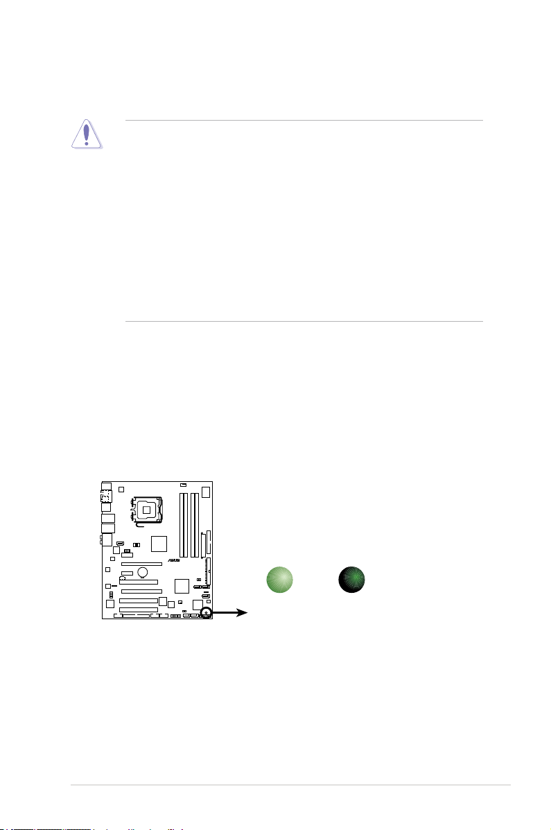
Onboard LED
The motherboard comes with a standby power LED. The green LED lights up
to indicate that the system is ON, in sleep mode, or in soft-off mode. This is a
reminder that you should shut down the system and unplug the power cable before
removing or plugging in any motherboard component. The illustration below shows
the location of the onboard LED.
ASUS P5W 2-1
Page 28
P5W
®
2.2 Motherboard overview
Before you install the motherboard, study the conguration of your chassis to
ensure that the motherboard ts into it.
Make sure to unplug the power cord before installing or removing the
motherboard. Failure to do so can cause you physical injury and damage
motherboard components.
2.2.1 Placement direction
When installing the motherboard, make sure that you place it into the chassis in
the correct orientation. The edge with external ports goes to the rear part of the
chassis as indicated in the image below.
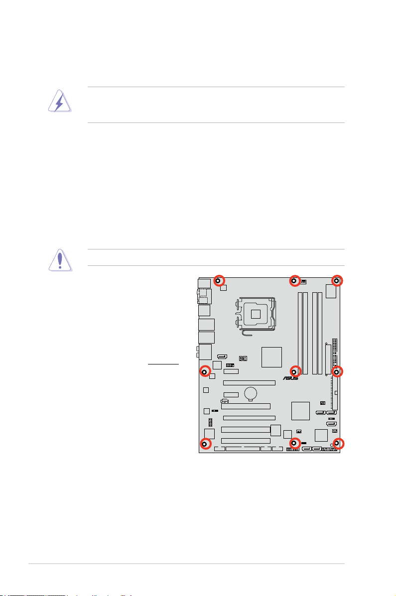
2.2.2 Screw holes
Place nine (9) screws into the holes indicated by circles to secure the motherboard
to the chassis.
Do not overtighten the screws! Doing so can damage the motherboard.
Place this side towards
the rear of the chassis
2-2 Chapter 2: Hardware information
Page 29
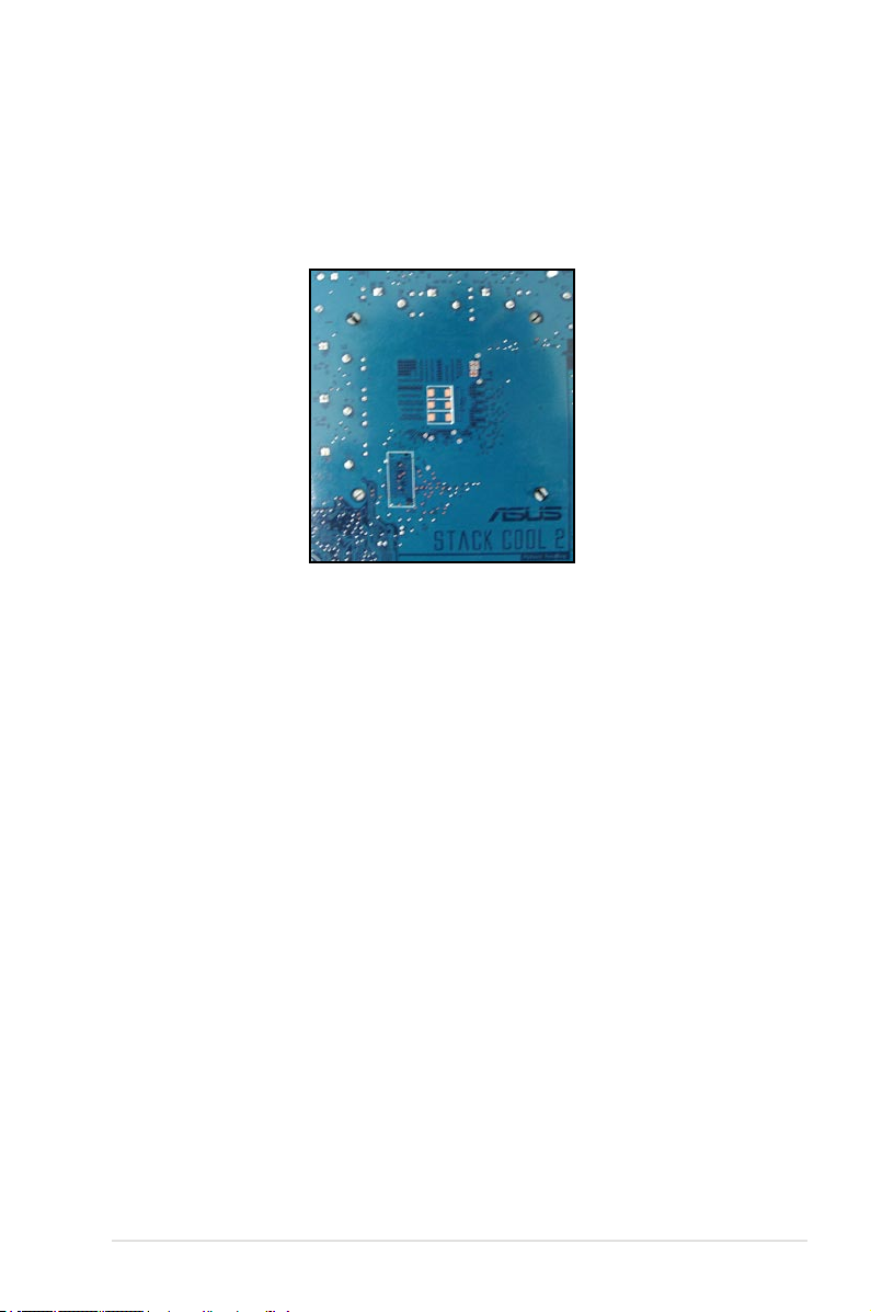
2.2.3 ASUS Stack Cool 2
The motherboard comes with the ASUS Stack Cool 2 cooling solution that lowers
the temperature of critical heat generating components by 20ºC. The motherboard
uses a special design on the printed circuit board (PCB) to dissipate heat that
critical components generate.
ASUS P5W 2-3
Page 30
PANEL
P5W
®
AAFP
CHASSIS
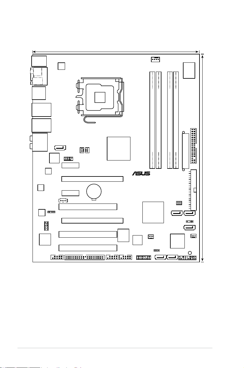
24.5cm (9.6in)
30.5cm (12.0in)
CPU_FAN
DDR2 DIMM_B1 (64 bit,240-pin module)
DDR2 DIMM_A1 (64 bit,240-pin module)
DDR2 DIMM_A2 (64 bit,240-pin module)
DDR2 DIMM_B2 (64 bit,240-pin module)
CHA_FAN2
FLOPPY
Super
I/O
8Mb
BIOS
TSB43AB22A
CD
PCIEX1_1
PCIEX16_2
CLRTC
SATA_RAID1
Intel
®
ICH7R
SB_PWR
EATXPWR
PRI_IDE
CR2032 3V
Lithium Cell
CMOS Power
Intel
®
MCH 975X
PCI1
USB56
LAN2_USB12
PS/2KBMS
T: Mouse
B: Keyboard
LAN1_USB34
AUDIO
PCIEX1_2
PCIEX16_1
PCI2
PCI3
ALC
882M
88E8053
88E8053
PWR_FAN1PWR_FAN2
JMicron
JMB363
SPDIF_OUT
USB910
LGA775
ESATA_1394
ATX12V
GL850A
Silicon Image
Sil4723
RAID_SEL
SATA4
CHA_FAN1
IE1394_1
USB78
SPDIF_O1
SPDIF_O2
COM1
EZ_RAID2 EZ_RAID1
SATA1
PRI_EIDE
SATA3
ADH
2.2.4 Motherboard layout
2-4 Chapter 2: Hardware information
Page 31

2.2.5 Layout contents
Slots Page
1. DDR2 DIMM slots 2-14
2. PCI slots
3. PCI Express x1 slot
4. PCI Express x16 slots
Jumpers Page
1. Clear RTC RAM (3-pin CLRTC) 2-26
2. ASUS EZ-Backup RAID mode selection (RAID_SEL)
Rear panel connectors Page
1. PS/2 mouse port (green) 2-28
2. Serial port
3. IEEE 1394a port
4. LAN1 (RJ-45) port
5. LAN2 (RJ-45) port
6. Center/Subwoofer port (yellow orange)
7. Rear Speaker Out port (black)
8. Line In port (light blue)
9. Line Out port (lime)
10. Microphone port (pink)
11. Side Speaker Out port (gray)
12. USB 2.0 ports 1,2, 3, and
13. External SATA port
14. Optical S/PDIF Out port
15. Coaxial S/PDIF Out port
16. PS/2 keyboard port (purple
4 2-29
) 2-30
2-24
2-24
2-24
2-27
2-28
2-28
2-28
2-28
2-28
2-28
2-29
2-29
2-29
2-29
2-29
2-30
2-30
ASUS P5W 2-5
Page 32

Internal connectors Page
1. Floppy disk drive connector (34-1 pin FLOPPY) 2-31
®
2. JMicron
3. Intel
4. Intel
IDE connector (40-1 pin PRI_EIDE [black]) 2-31
®
ICH7R IDE connector (40-1 pin PRI_IDE) 2-32
®
ICH7R Serial ATA connectors (7-pin SATA1 [red],
2-33
SATA3 [black], SATA4 [black],)
5. JMicron
JMB363 Serial ATA connector
2-34
®
(7-pin SATA_RAID1 [red])
6. ASUS EZ-Backup
Serial ATA connectors
2-35
(7-pin EZ_RAID1 [orange], EZ_RAID2 [orange])
7. Internal audio connector (4-pin CD)
2-35
8. Front panel audio connector (10-1 pin AAFP) 2-36
9. USB connector (10-1 pin USB56, USB78)
10. IEEE 1394a port connector (10-1 pin IE1394_1 [Red])
11. Chassis intrusion connector (4-1 pin CHASSIS)
12. CPU, Chassis, and Power Fan connectors (4-pin CPU_FAN,
2-37
2-37
2-38
2-38
3-pin PWR_FAN1, 3-pin PWR_FAN2, 3-pin CHA_FAN1,
3-pin CHA_FAN2)
13. ATX power connectors (24-pin EATXPWR, 4-pin ATX12V)
14. System panel connector (20-pin PANEL)
•
System power LED (2-pin PLED)
•
Hard disk drive activity LED (2-pin IDE_LED)
•
System warning speaker (4-pin SPEAKER)
•
ATX power button/soft-off button (2-pin PWRSW)
•
Reset button (2-pin RESET)
2-40
2-42
2-6 Chapter 2: Hardware information
Page 33

2.3 Central Processing Unit (CPU)
The motherboard comes with a surface mount LGA775 socket designed for the
Intel® Pentium® 4/Celeron®/Intel® Pentium® D and the Intel® next generation 65
nm Intel® Core™2 Duo and Intel® Core™2 Extreme multi-core processor in the
775-land package.
This motherboard also supports the Intel® Pentium® Processor Extreme Edition, the
latest CPU with embedded dual physical cores and Hyper-Threading technology,
making four CPU threads possible. Refer to the table below for the operating
system support status.
OS licensing support list
Intel® Dual-Core CPU support Intel® Dual-Core CPU and
Windows® 2000 Professional
Windows® 2000 Advanced Server Windows® 2000 Advanced Server
Windows® XP Home Windows® XP Home
Windows® XP Professional Windows® XP Professional
Windows® Server 2003 - Standard,
Enterprise
• If installing a dual-core CPU, connect the chassis fan cable to the
PWR_FAN1/2 or CHA_FAN1/2 connector to ensure system stability.
•
Install a chassis fan with at least a speed of 2400 rpm and 8 CFM turnrate
when using a dual-core CPU to ensure system stability. Overheating can
permanently damage the system and/or CPU.
• Install an additional chassis fan to ensure better air ow when overclocking.
• Upon purchase of the motherboard, make sure that the PnP cap is on
the socket and the socket contacts are not bent. Contact your retailer
immediately if the PnP cap is missing, or if you see any damage to the PnP
cap/socket contacts/motherboard components. ASUS will shoulder the cost
of repair only if the damage is shipment/transit-related.
•
Keep the cap after installing the motherboard. ASUS will process Return
Merchandise Authorization (RMA) requests only if the motherboard comes
with the cap on the LGA775 socket.
• The product warranty does not cover damage to the socket contacts
resulting from incorrect CPU installation/removal, or misplacement/loss/
incorrect removal of the PnP cap.
Hyper-Threading Technology support
Windows® Server 2003 - Standard,
Enterprise
ASUS P5W 2-7
Page 34

2.3.1 Installing the CPU
P5W
®
P5W CPU Socket 775
To install a CPU:
1. Locate the CPU socket on the motherboard.
Before installing the CPU, make sure that the cam box is facing towards you
and the load lever is on your left.
2. Press the load lever with your thumb (A), then move it to the left (B) until it is
released from the retention tab.
Retention tab
A
Load lever
B
This side of the socket box
should face you.
To prevent damage to the socket pins, do not remove the PnP cap unless you
are installing a CPU.
3. Lift the load lever in the direction of
the arrow to a 135º angle.
2-8 Chapter 2: Hardware information
PnP cap
Page 35

4. Lift the load plate with your thumb
and forenger to a 100º angle (A),
then push the PnP cap from the load
plate window to remove (B).
Alignment key
5. Position the CPU over the
socket, making sure that
the gold triangle is on the
bottom-left corner of the
socket then t the socket
alignment key into the
CPU notch.
The CPU ts in only one correct orientation. DO NOT force the CPU into the
socket to prevent bending the connectors on the socket and damaging the CPU!
CPU notch
Gold triangle mark
B
A
Load plate
6. Close the load plate (A), then
A
push the load lever (B) until it
snaps into the retention tab.
7. If installing a dual-core CPU,
connect the chassis fan cable to
B
the PWR_FAN1/2 or
CHA_FAN1/2 connector to
ensure system stability.
The motherboard supports Intel® Pentium® 4 LGA775 processors with the
Intel® Enhanced Memory 64 Technology (EM64T), Enhanced Intel SpeedStep®
Technology (EIST), and Hyper-Threading Technology. Refer to the Appendix for
more information on these CPU features.
ASUS P5W 2-9
Page 36

2.3.2 Installing the CPU heatsink and fan
The Intel® Pentium® 4 LGA775 processor requires a specially designed heatsink
and fan assembly to ensure optimum thermal condition and performance.
•
When you buy a boxed Intel® Pentium® 4 processor, the package
includes the CPU fan and heatsink assembly. If you buy a CPU separately,
make sure that you use only Intel®-certied multi-directional heatsink and
fan.
•
Your Intel® Pentium® 4 LGA775 heatsink and fan assembly comes in a
push-pin design and requires no tool to install.
•
If you purchased a separate CPU heatsink and fan assembly, make sure
that you have properly applied Thermal Interface Material to the CPU
heatsink or CPU before you install the heatsink and fan assembly.
Make sure that you have installed the motherboard to the chassis before you
install the CPU fan and heatsink assembly.
To install the CPU heatsink and fan:
1. Place the heatsink on top of the
installed CPU, making sure that
the four fasteners match the holes
on the motherboard.
Orient the heatsink and fan
assembly such that the CPU fan
cable is closest to the CPU fan
connector.
Motherboard hole
Narrow end
of the groove
Make sure to orient each fastener with the narrow end of the groove pointing
outward. (The photo shows the groove shaded for emphasis.)
2-10 Chapter 2: Hardware information
Fastener
Page 37

2. Push down two fasteners at a time
P5W DH DELUXE
®
P5W DH DELUXE CPU fan connector
CPU_FAN
GND
CPU FAN PWR
CPU FAN IN
CPU FAN PWM
in a diagonal sequence to secure
the heatsink and fan assembly in
place.
B
A
A
A
B
B
A
B
3. Connect the CPU fan cable to the connector on the motherboard labeled
CPU_FAN.
Do not forget to connect the CPU fan connector! Hardware monitoring errors
can occur if you fail to plug this connector.
ASUS P5W 2-11
Page 38

2.3.3 Uninstalling the CPU heatsink and fan
To uninstall the CPU heatsink and fan:
1. Disconnect the CPU fan cable from
the connector on the motherboard.
2. Rotate each fastener
counterclockwise.
3. Pull up two fasteners at a time in
a diagonal sequence to disengage
the heatsink and fan assembly
from the motherboard.
A
B
A
A
B
B
A
B
4. Carefully remove the heatsink
and fan assembly from the
motherboard.
2-12 Chapter 2: Hardware information
Page 39

5. Rotate each fastener clockwise to
ensure correct orientation when
reinstalling.
The narrow end of the groove
should point outward after
resetting. (The photo shows the
groove shaded for emphasis.)
Narrow end of the groove
Refer to the documentation in the boxed or stand-alone CPU fan package for
detailed information on CPU fan installation.
ASUS P5W 2-13
Page 40

2.4 System memory
P5W
®
P5W 240-pin DDR2 DIMM sockets
DIMM_A2
DIMM_A1
DIMM_B2
DIMM_B1
2.4.1 Overview
The motherboard comes with four Double Data Rate 2 (DDR2) Dual Inline Memory
Modules (DIMM) sockets.
A DDR2 module has the same physical dimensions as a DDR DIMM but has a
240-pin footprint compared to the 184-pin DDR DIMM. DDR2 DIMMs are notched
differently to prevent installation on a DDR DIMM socket.
The gure illustrates the location of the DDR2 DIMM sockets:
Channel Sockets
Channel A DIMM_A1 and DIMM_A2
Channel B DIMM_B1 and DIMM_B2
2.4.2 Memory congurations
You may install 256 MB, 512 MB, 1 GB, and 2 GB unbuffered ECC/non-ECC
DDR2 DIMMs into the DIMM sockets.
• For dual-channel conguration, the total size of memory module(s) installed
per channel must be the same (DIMM_A1 + DIMM_A2 = DIMM_B1 +
DIMM_B2).
• Always install DIMMs with the same CAS latency. For optimum
compatibility, it is recommended that you obtain memory modules from
the same vendor. Visit the ASUS website (www.asus.com) for the latest
Qualied Vendors List.
• For dual-channel memory conguration, install the DIMMs in slots
DIMM_B1 and DIMM_A1 (orange slots); install another pair of DIMMs in
slots DIMM_B2 and DIMM_A2 (black slots).
2-14 Chapter 2: Hardware information
Page 41

Important notice on installing Windows® XP 32-bit version
If you install Windows® XP 32-bit version Operating System (OS), the limitation
of this OS version is that it may reserve a certain amount of memory space for
system devices. We recommend that you install less than 3 GB system memory
if you would like to work under Windows® XP 32-bit version OS. The excess
memory installation will not cause any usage problem, but it will not give users
the benet of manipulating this excess memory space.
Visit the ASUS FAQ site for further
explanation:
http://support.asus.com/faq/faq.
aspx?SLanguage=en-us
Under General Search, make the
selections as shown, then click Search.
Click the article titled “4GB memory installed but less memory size
detected.”
You also may check the URLs below for third party comments on this issue:
http://dlsvr01.asus.com/pub/ASUS/mb/4GB_Rev1.pdf
http://www.intel.com/support/motherboards/server/sb/cs-016594.htm
Notes on memory limitations
• Due to chipset limitation, this motherboard can only support up to
8 GB on the operating systems listed below. You may install a maximum of
2 GB DIMMs on each slot.
32-bit 64-bit
Windows® 2000 Advanced Server
Windows® Server 2003 Enterprise
Edition
Windows® Server 2003 Standard
x64 Edition
Windows® XP Professional x64
Enterprise Edition
Windows® Server 2003 Enterprise
x64 Edition
• Some old-version DDR2-667 DIMMs may not match Intel®’s
On-Die-Termination (ODT) requirement and will automatically downgrade
to run at DDR2-533. If this happens, contact your memory vendor to check
the ODT value.
• Due to chipset limitation, DDR2-667 with CL=4 will be downgraded to run
at DDR2-533 by default setting. If you want to operate with lower latency,
adjust the memory timing manually.
• Due to chipset limitation, DDR2-533 with CL=3 will be downgraded to run
at DDR2-400 by default setting. If you want to operate with lower latency,
adjust the memory timing manually.
ASUS P5W 2-15
Page 42

Qualied Vendors Lists
DDR2-800
Size Vendor Chip No. Chip
512 MB KINGSTON Heat-Sink Package
512 MB KINGSTON K4T51083QC
1024 MB KINGSTON K4T51083QC
256 MB SAMSUNG K4T56083QF-ZCE7
256 MB SAMSUNG K4T56083QF-ZCE7(ECC)
512 MB SAMSUNG EDD339XX
512 MB Inneon HYB18T256800AF25
512 MB Hynix HY5PS12821AFP-S6
1024 MB Hynix HY5PS12821AFP-S6
512 MB MICRON 5JAIIZ9DQQ
1024 MB MICRON 5JAIIZ9DQQ
512 MB CORSAIR Heat-Sink Package
1024 MB CORSAIR Heat-Sink Package
256 MB A-DATA E2508AB-GE-E
256 MB A-DATA E2508AB-GE-E
256 MB A-DATA E2508AB-GE-E
512 MB A-DATA E2508AB-GE-E
256 MB Apacer E2508AB-GE-E
512 MB Apacer E2508AB-GE-E
512 MB Crucial Heat-Sink Package
1024 MB Crucial Heat-Sink Package
256 MB TwinMOS E2508AB-GE-E
512 MB OCZ Heat-Sink Package
512 MB Elixir N2TU51280AE-25C
512 MB NANYA NT5TU64M8AE-25C
512 MB NANYA NT5TU64M8BE-25C
1024 MB NANYA NT5TU64M8BE-25C – DS NT1GT64U8HB0BY-25C –
Side(s) Part No. CL DIMM socket
brand
–
SS KHX6400D2/512
–
SS KVR800D2N5/512
–
DS KVR800D2N5/1G
–
SS M378T3253FZ3-CE7
–
SS M391T3253FZ3-CE7
–
SS M378T6553CZ3-CE7
–
DS HYS64T64520HU-2.5-A
–
SS HYMP564U64AP8-S6
–
DS HYMP512U64AP8-S6
–
SS MT8HTF6464AY-80EA3
–
DS MT16HTF12864AY-80EA3
–
SS CM2X512A-6400
–
DS CM2X1024-6400PRO
–
SS M20EL6F3G3170A1D0Z
–
SS M20EL6F3G3160A1D0Z
–
SS M2OEL6F3G3160A1D0Z
–
DS M2OEL6F3H4170A1D0Z
–
SS 78.81091.420
–
DS 78.91091.420
–
SS BL6464AA804.8FA
–
DS BL12864AA804.16FA
–
SS 8G-24IK2-EBT
–
SS OCZ28001024EBDCPE-K
–
SS M2Y51264TU88A2B-25C
–
SS NT512T64U88A1BY-25C
–
SS NT512T64U88B0BY-25C
–
–
–
–
–
–
– • • •
–
–
– • • •
– • • •
–
– • • •
–
–
–
–
–
–
–
–
–
–
–
–
–
support
(Optional)
A* B* C*
• •
• •
• •
• •
• •
•
• •
•
Side(s): SS - Single-sided DS - Double-sided
DIMM support:
A - Supports one module inserted into either slot, in Single-channel memory conguration.
B - Supports one pair of modules inserted into either the orange slots or the black slots as
one pair of Dual-channel memory conguration.
C - Supports two pairs of modules inserted into both the orange and black slots as two pairs
of Dual-channel memory conguration.
Visit the ASUS website for the latest DDR2-800 with lower latency Qualied
Vendors List.
2-16 Chapter 2: Hardware information
Page 43

DDR2-667
Size Vendor Chip No. Chip
512MB KINGSTON E5108AE-6E-E – SS K•R667D2N5/512 – • •
1024MB KINGSTON E5108AE-6E-E – DS K•R667D2N5/1G – • • •
512MB KINGSTON E5108AE-6E-E – SS K•R667D2E5/512 – • • •
256MB KINGSTON HYB18T256800AF3 – SS K•R667D2N5/256 – • • •
256MB SAMSUNG K4T56083QF-ZCE6 – SS M378T3253FZ0-CE6 – • • •
512MB SAMSUNG K4T56083QF-ZCE6 – DS M378T6453FZ0-CE6 – • • •
256MB SAMSUNG K4T56083QF-ZCE6(ECC) – SS M391T3253FZ0-CE6 – • •
512MB SAMSUNG K4T56083QF-ZCE6(ECC) – DS M391T6453FZ0-CE6 – •
256MB SAMSUNG K4T51163QC-ZCE6 – SS M378T3354CZ0-CE6 – • • •
512MB SAMSUNG ZCE6K4T51083QC – SS M378T6553CZ0-CE6 – •
1024MB SAMSUNG ZCE6K4T51083QC – DS M378T2953CZ0-CE6 – • • •
512MB MICRON 4•B41D9CZM – DS MT16HTF6464AY-667B4 – • •
256MB Inneon HYB18T512160AF-3S – SS HYS64T32000HU-3S-A – • • •
512MB Inneon HYB18T512800AF3S – SS HYS64T64000HU-3S-A – • •
1024MB Inneon HYB18T512800AF3S – DS HYS64T128020HU-3S-A – • • •
256MB Inneon HYB18T256800AF3S(ECC) – SS HYS72T32000HU-3S-A – • •
512MB Inneon HYB18T512800AF3S(ECC) – SS HYS72T64000HU-3S-A – • • •
1024MB Inneon HYB18T512800AF3S(ECC) – DS HYS72T128020HU-3S-A – • •
512MB Hynix HY5PS12821AFP-Y5 – SS HYMP564U64AP8-Y5 – • • •
1024MB Hynix HY5PS12821AFP-Y5 – DS HYMP512U64AP8-Y5 – • • •
1024MB Hynix HY5PS1G831FP-Y5(ECC) – SS HYMP112U72P8-Y5 – •
512MB Hynix HY5PS12821AFP-Y5(ECC) – SS HYMP564U72AP8-Y5 – • • •
1024MB Hynix HY5PS12821AFP-Y5(ECC) – DS HYMP512U72AP8-Y5 – • • •
512MB Hynix HY5PS12821AFP-Y4 – SS HYMP564U64AP8-Y4 – • • •
1024MB Hynix HY5PS12821AFP-Y4 – DS HYMP512U64AP8-Y4 – • • •
512MB Hynix HY5PS12821AFP-Y4(ECC) – SS HYMP564U72AP8-Y4 – • •
1024MB Hynix HY5PS12821AFP-Y4(ECC) – DS HYMP512U72AP8-Y4 – • •
256MB ELPIDA E2508AB-6E-E – SS EBE25UC8ABFA-6E-E – • •
512MB ELPIDA E5108AE-6E-E – SS EBE51UD8AEFA-6E-E – • • •
1024MB ELPIDA Engineering Sample – DS EBE11UD8AEFA-6E-E – • •
512MB crucial Heat-Sink Package – DS BL6464AA664.16FB – • • •
1024MB crucial Heat-Sink Package – DS BL12864AA664.16FA – • •
512MB crucial Heat-Sink Package – DS BL6464AL664.16FB – • • •
1024MB crucial Heat-Sink Package – DS BL12864AL664.16FA – • • •
512MB crucial Heat-Sink Package – DS BL6464AA663.8FA – •
1024MB crucial Heat-Sink Package – DS BL12864AA663.16FA – • • •
512MB Kingmax E5108AE-6E-E – SS KLCC28F-A8EB5 – • •
1024MB Kingmax E5108AE-6E-E – DS KLCD48F-A8EB5 – • •
512MB Apacer E5108AE-6E-E – SS 78.91092.420 – •
1024MB Apacer E5108AE-6E-E – DS 78.01092.420 –
512MB A-DATA E5108AE-6E-E – SS M20EL5G3H3160B1C0Z – •
512MB TwinMOS E5108AE-GE-E – SS 8G-25JK5-EBT –
512MB GEIL Heat-Sink Package – SS GX21GB5300UDC –
(continued on the next page)
Side(s) Part No. CL DIMM socket
brand
support
(Optional)
A* B* C*
ASUS P5W 2-17
Page 44

DDR2-667
Size Vendor Chip No. Chip
512MB GEIL Heat-Sink Package – SS GX21GB5300DC –
256MB NANYA NT5TU32M16AG-3C – SS NT256T64UH4A0FY-3C –
512MB NANYA NT5TU64M8AE-3C – SS NT512T64U88A0BY-3C –
512MB NANYA NT5TU64M8BE-3B – SS NT512T64U88B0BY-3C –
1024MB NANYA NT5TU64M8BE-3B – DS NT1GT64U8HB0BY-3C –
512MB Elixir N2TU51280AF-3C – SS M2U51264TU88A0F-3C –
1024MB Elixir N2TU51280AF-3C – DS M2U1G64TU8HA2F-3C –
512MB OCZ Heat-Sink Package – SS OCZ26671024EBDCPE-K –
1024MB OCZ Heat-Sink Package – DS OCZ26672048EBDCPE-K –
1024MB PQI E5108AE-5C-E – DS MEAD-403LA –
512MB WINTEC 4UAI2D9CRZ – SS 39127282 –
1024MB WINTEC 4WAIID9CWX – DS 39137282 –
512MB MDT 18D51280D-30518 – SS M512-667-8 –
1024MB MDT 18D51280D-30528 – DS M924-667-16 –
512MB Kingbox DD2640800-667 – SS – –
1024MB Kingbox DD2640800-667 – DS – –
Side(s): SS - Single-sided DS - Double-sided
DIMM support:
A - Supports one module inserted into either slot, in Single-channel memory conguration.
B - Supports one pair of modules inserted into either the orange slots or the black slots as
one pair of Dual-channel memory conguration.
C - Supports two pairs of modules inserted into both the orange and black slots as two pairs
of Dual-channel memory conguration.
Visit the ASUS website for the latest DDR2-667 with lower latency Qualied
Vendors List.
Side(s) Part No. CL DIMM socket
brand
support
(Optional)
A* B* C*
2-18 Chapter 2: Hardware information
Page 45

DDR2-533
Size Vendor Chip No. Chip
256 MB KINGSTON E5116AF-5C-E – SS KVR533D2N4/256 –
512 MB KINGSTON HYB18T512800AF37 – SS KVR533D2N4/512 – • • •
1024 MB KINGSTON 5YDIID9GCT – DS KVR533D2N4/1G – • • •
512 MB SAMSUNG K4T51083QB-GCD5 – SS M378T6553BG0-CD5 – •
256 MB SAMSUNG K4T56083QF-GCD5 – SS M378T3253FG0-CD5 – • •
512 MB SAMSUNG K4T56083QF-GCD5 – DS M378T6453FG0-CD5 –
512 MB SAMSUNG K4T56083QF-GCD5(ECC) – DS M391T6453FG0-CD5 – •
1024 MB SAMSUNG K4T51083QB-GCD5(ECC) – DS M391T2953BG0-CD5 – •
256 MB MICRON 4DBIIZ9BQT – SS N/A – • •
512 MB Inneon HYB18T512800AF3(ECC) – SS HYS72T64000HU-3.7-A –
512 MB Inneon HYB18T512800AC37 – SS HYS64T64000GU-3.7-A – • • •
256 MB Inneon HYB18T512160AF-3.7 – SS HYS64T32000HU-3.7-A – • • •
512 MB Inneon HYB18T512800AF37 – SS HYS64T64000HU-3.7-A – • • •
1024 MB Inneon HYB18T512800AF37 – DS HYS64T128020HU-3.7-A – • • •
2048 MB Inneon HYB18T1G800AF-3.7 – DS HYS64T256020HU-3.7-A –
256 MB Inneon HYB18T5121608BF-3.7 – SS HYS64T32000HU-3.7-B – • •
512 MB Inneon HYB18T512800BF37 – SS HYS64T64000HU-3.7-B – • •
1024 MB Inneon HYB18T512800BF37 – DS HYS64T128020HU-3.7-B –
512 MB Hynix HY5PS12821F-C4 – SS HYMP564U648-C4 – • •
512 MB Hynix HY5PS12821F-C4(ECC) – SS HYMP564U728-C4 –
1024 MB Hynix HY5PS12821F-C4 – DS HYMP512U648-C4 – • • •
1024 MB Hynix HY5PS12821F-C4(ECC) – DS HYMP512U728-C4 – • •
1024 MB Hynix HY5PS12821F-E3(ECC) – DS HYMP512U728-C4 –
512 MB Hynix HY5PS12821FP-C4(ECC) – SS HYMP564U728-C4 – • • •
1024 MB Hynix HY5PS12821FP-C4 – DS HYMP512U648-C4 –
512 MB Hynix HY5PS12821AFP-C3 – SS HYMP564U64AP8-C3 – • • •
1024 MB Hynix HY5PS12821AFP-C3 – DS HYMP512U64AP8-C3 – •
512 MB ELPIDA E5108AB-5C-E(ECC) – SS EBE51ED8ABFA-5C-E – • • •
512 MB ELPIDA E5108AB-5C-E – SS EBE51UD8ABFA-5C – • •
512 MB ELPIDA E5108AB-5C-E – SS EBE51UD8ABFA-5C-E – • • •
1024 MB ELPIDA E5108AB-5C-E – DS EBE11UD8ABFA-5C-E –
2048 MB ELPIDA E1108AA-5C-E – DS EBE21EE8AAFA-5C-E –
256 MB CORSAIR MIII0051832M8CEC – SS VS256MB533D2 –
512 MB CORSAIR MI110052432M8CEC – DS VS512MB533D2 –
256 MB Apacer E5116AB-5C-E – SS 78.81077.420 – • • •
256 MB KINGMAX E5116AB-5C-E – SS KLBB68F-36EP4 – • •
512 MB KINGMAX E5108AE-5C-E – SS KLBC28F-A8EB4 – •
1024 MB KINGMAX E5108AE-5C-E – DS KLBD48F-A8EB4 – • •
512 MB KINGMAX KKEA88E4AAK-37 – SS KLBC28F-A8KE4 – • •
1024 MB KINGMAX 5MB22D9DCN – DS KLBD48F-A8ME4 – •
512 MB Transcend K4T51083QB-GCD5 – SS TS64MLQ64V5J – •
1024 MB Transcend K4T51083QB-GCD5 – DS TS128MLQ64V5J – • •
256 MB CENTURY K4T56083QF-GCD5 – SS 25V6S8SSD5F4-K43 –
512 MB CENTURY E5108AB-5C-E – SS 25V2H8EL5CB4-J43 –
1024 MB CENTURY E5108AB-5C-E – DS 25V0H8EL5CB4-J45 –
1024 MB CENTURY E5108AB-5C-E – DS 25VOH8EL5C –
256 MB elixir N2TU51216AF-37B – SS M2U25664TUH4A0F-37B –
512 MB elixir N2TU51280AF-37B – SS M2U51264TU88A0F-37B –
256 MB Aeneon AET960UD00-37C88X – SS AET560UD00-370A98X –
Side(s) Part No. CL DIMM socket
brand
support
(Optional)
A* B* C*
(continued on the next page)
ASUS P5W 2-19
Page 46

DDR2-533
Size Vendor Chip No. Model Side(s) Part No. CL DIMM socket
512 MB Aeneon AET960UD00-37C88X – SS AET660UD00-370A98X –
512 MB Aeneon AET93F370AG0513 – SS AET660UD00-370A98X –
256 MB Aeneon AET94F370A – SS AET560UD00-370A98Z –
256 MB Aeneon AET94F370A – SS AET560UD00-370A98X –
512 MB Aeneon AET93F370A – SS AET660UD00-370A98Z –
512 MB Aeneon AET93F370A – SS AET660UD00-370A98X –
512 MB Aeneon AET93F370 – SS AET660UD00-370A98X –
1024 MB Aeneon AET93F370A – DS AET760UD00-370A98X –
256 MB NANYA NT5TU32M16AF-37B – SS NT256T64UH4A0F-37B –
512 MB NANYA NT5TU64M8AF-37B – SS NT512T64U88A0F-37B –
512 MB NANYA NT5TU64M8AF-37B(ECC) – SS NT512T72U89A0F-37B –
1024 MB NANYA NT5TU64M8AF-37B – DS NT1GT64U8HA0F-37B –
1024 MB PQI 64MX8D2-E – DS MEAB-323LA –
512 MB PQI 64MX8D2-E – SS MEAB-423LA –
512 MB TwinMOS K4T51083QB-GCD5 – SS 8D-22JB5-K2T –
256 MB SimpleTech 858S032F25A – SS SVM-42DR2/256 –
512 MB SimpleTech 858S064F25A – SS SVM-42DR2/512 –
1024 MB Patriot Heat-Sink Package – SS PDC21G5600+XBLK –
512 MB MDT 18D51280D-3.70S20 – SS M512-533-8 –
1024 MB MDT 18D51280D-3.70448 – DS M924-533-16 –
Side(s): SS - Single-sided DS - Double-sided
DIMM support:
A - Supports one module inserted into either slot, in Single-channel memory conguration.
B - Supports one pair of modules inserted into either the orange slots or the black slots as
one pair of Dual-channel memory conguration.
C - Supports two pairs of modules inserted into both the orange and black slots as two pairs
of Dual-channel memory conguration.
support
(Optional)
A* B* C*
Visit the ASUS website for the latest DDR2-533 with lower latency Qualied
Vendors List.
2-20 Chapter 2: Hardware information
Page 47

2.4.3 Installing a DIMM
Unplug the power supply before adding or removing DIMMs or other
system components. Failure to do so can cause severe damage to both the
motherboard and the components.
To install a DIMM:
1. Unlock a DIMM socket by
pressing the retaining clips
outward.
2. Align a DIMM on the socket
such that the notch on the
DIMM matches the break on the
1
socket.
3. Firmly insert the DIMM into the
socket until the retaining clips
snap back in place and the
DIMM is properly seated.
• A DDR2 DIMM is keyed with a notch so that it ts in only one direction. Do
not force a DIMM into a socket to avoid damaging the DIMM.
• The DDR2 DIMM sockets do not support DDR DIMMs. Do not install DDR
DIMMs to the DDR2 DIMM sockets.
2.4.4 Removing a DIMM
To remove a DIMM:
1. Simultaneously press the retaining
clips outward to unlock the DIMM.
3
DDR2 DIMM notch
Unlocked retaining clip
2
2
Support the DIMM lightly with
your ngers when pressing the
retaining clips. The DIMM might
get damaged when it ips out
with extra force.
1
DDR2 DIMM notch
1
2. Remove the DIMM from the socket.
ASUS P5W 2-21
Page 48

2.5 Expansion slots
In the future, you may need to install expansion cards. The following sub-sections
describe the slots and the expansion cards that they support.
Make sure to unplug the power cord before adding or removing expansion
cards. Failure to do so may cause you physical injury and damage motherboard
components.
2.5.1 Installing an expansion card
To install an expansion card:
1. Before installing the expansion card, read the documentation that came with
it and make the necessary hardware settings for the card.
2. Remove the system unit cover (if your motherboard is already installed in a
chassis).
3. Remove the bracket opposite the slot that you intend to use. Keep the screw
for later use.
4. Align the card connector with the slot and press rmly until the card is
completely seated on the slot.
5. Secure the card to the chassis with the screw you removed earlier.
6. Replace the system cover.
2.5.2 Conguring an expansion card
After installing the expansion card, congure the it by adjusting the software
settings.
1. Turn on the system and change the necessary BIOS settings, if any. See
Chapter 4 for information on BIOS setup.
2. Assign an IRQ to the card. Refer to the tables on the next page.
3. Install the software drivers for the expansion card.
When using PCI cards on shared slots, ensure that the drivers support “Share
IRQ” or that the cards do not need IRQ assignments. Otherwise, conicts will
arise between the two PCI groups, making the system unstable and the card
inoperable. Refer to the table on the next page for details.
2-22 Chapter 2: Hardware information
Page 49

2.5.3 Interrupt assignments
IRQ Priority Standard function
0 1 System Timer
1 2
2 – Redirect to IRQ#9
3 11 IRQ Holder for PCI Steering*
4 12 Communications Port (COM1)*
5 13 IRQ Holder for PCI Steering*
6 14 Floppy Disk Controller
7 15 Printer Port (LPT1)*
8 6 System CMOS/Real Time Clock
9 4 IRQ Holder for PCI Steering*
10 5 IRQ Holder for PCI Steering*
11 6 IRQ Holder for PCI Steering*
12 7 PS/2 Compatible Mouse Port*
13 8 Numeric Data Processor
14 9 Primary IDE Channel
15 10 Secondary IDE Channel
* These IRQs are usually available for ISA or PCI devices.
IRQ assignments for this motherboard
PCI slot 1 – – – – shared – –
PCI slot 2 – – – – – – shared –
PCI slot 3 – – – – – – – shared
Onboard IDE (JMicron®) – shared – – – – – –
Onboard 1394 – – – – – shared – –
Onboard LAN1 – – – shared – – – –
Onboard LAN2 shared – – – – – – –
PCIE x16 1 shared – – – – – – –
PCIE x16 2 shared – – – – – – –
PCIE x1 shared – – – – – – –
PCIE x1 – – shared – – – – –
USB controller 1 – – – – shared – – –
USB controller 2 – shared – – – – – –
USB controller 3 – – shared – – – – –
USB controller 4 – – – shared – – – –
USB 2.0 controller – – – – shared – – –
Serial ATA – – – – – – – shared
IDE – – – – – – shared –
HD Audio – – – shared – – – –
Keyboard Controller
A B C D E F G H
ASUS P5W 2-23
Page 50

2.5.4 PCI slots
The PCI slots support cards such as
a LAN card, SCSI card, USB card,
and other cards that comply with PCI
specications. The gure shows a LAN
card installed on a PCI slot.
2.5.5 PCI Express x1 slot
This motherboard supports PCI Express
x1 network cards, SCSI cards and other
cards that comply with the PCI Express
specications. The following gure
shows a network card installed on the
PCI Express x1 slot.
2.5.6 Two PCI Express x16 slots
This motherboard supports two ATI
CrossFire™ PCI Express x16 graphics
cards that comply with the PCI Express
specications.
The gure shows two graphics cards
installed on the PCI Express x16 slots.
See Chapter 6 for details on the
CrossFire™ technology feature.
2-24 Chapter 2: Hardware information
Page 51

• We recommend that you install a graphics card on the primary (orange)
PCI Express slot and install other PCI Express devices on the black PCI
Express x16 slot.
• In CrossFire™ mode, each PCI Express x16 slot works at x8 bandwidth.
• In CrossFire™ mode, install the ATI CrossFire™ Edition (Master) graphics
card on the primary (orange) PCI Express slot.
• Refer to the table below for possible PCI Express Card congurations.
PCI Express x16 slot congurations
PCIEX16_1 (orange) slot PCIEX16_2 (black) slot
Card type Speed Card type Speed
Non-CrossFire™
mode
PCIe x16 graphics card x16 NA NA
PCIe x16 graphics card x8 Other PCIe x16
PCIe x16 graphics card x8 Other PCIe card x8, x4, x1**
graphics card
x8** (dual
screen)
Dual
graphics cards
in CrossFire™
mode*
ASUS P5W 2-25
ATI® CrossFire™ Edition
graphics card
* Install two ATI graphics cards from the same GPU family that support
CrossFire™ mode.
** The speed of the primary PCIe x16 slot (PCIEX16_1) changes to x8 mode
after you install any device in the secondary PCIe x16 (PCIEX16_2) slot.
x8 ATI graphics card x8
Page 52

2.6 Jumpers
P5W
®
P5W Clear RTC RAM
CLRTC
Normal Clear RTC
(Default)
1 2 2 3
1. Clear RTC RAM (CLRTC)
This jumper allows you to clear the Real Time Clock (RTC) RAM in
CMOS. You can clear the CMOS memory of date, time, and system setup
parameters by erasing the CMOS RTC RAM data. The onboard button
cell battery powers the RAM data in CMOS, which include system setup
information such as system passwords.
To erase the RTC RAM:
1. Turn OFF the computer and unplug the power cord.
2. Remove the onboard battery.
3. Move the jumper cap from pins 1-2 (default) to pins 2-3. Keep the cap on
pins 2-3 for about 5~10 seconds, then move the cap back to pins 1-2.
4. Reinstall the battery.
5. Plug the power cord and turn ON the computer.
6. Hold down the <Del> key during the boot process and enter BIOS setup
to re-enter data.
Except when clearing the RTC RAM, never remove the cap on CLRTC jumper
default position. Removing the cap will cause system boot failure!
You do not need to clear the RTC when the system hangs due to overclocking.
For system failure due to overclocking, use the C.P.R. (CPU Parameter Recall)
feature. Shut down and reboot the system so the BIOS can automatically reset
parameter settings to default values.
2-26 Chapter 2: Hardware information
Page 53

2. ASUS EZ-Backup RAID mode selection (RAID_SEL)
P5W
®
P5W RAID Setting
RAID_SEL
RAID1
(Default)
1
BIG
mode1[Fast mode]
1
RAID0
[Safe mode]
This jumper allows you to select the ASUS EZ-Backup RAID mode. Keeping
the default setting RAID 1 allows you to build a RAID 1 set without any
jumper or BIOS setting. Install the ASUS EZ-Backup Manager utility from the
support CD and install two Serial ATA hard disk drives on the EZ_RAID1 and
EZ_RAID2 connectors on the motherboard, and you are ready to mirror your
data.
For detailed information about ASUS EZ-Backup, see section “5.4.4 Silicon
Image® RAID conguration.”
ASUS P5W 2-27
Page 54

2.7 Connectors
1
16
4 2 3 5 6
12 10 11 13 14 15
8 9 7
2.7.1 Rear panel connectors
1. PS/2 mouse port (green). This port is for a PS/2 mouse.
2. Serial port.
devices.
3. IEEE 1394a port.
connectivity for audio/video devices, storage peripherals, PCs, or portable
devices.
4. LAN1 (RJ-45) port.
Local Area Network (LAN) through a network hub. Refer to the table below
for the LAN port LED indications.
5. LAN2 (RJ-45) port.
Local Area Network (LAN) through a network hub. Refer to the table below
for the LAN port LED indications.
This 9-pin COM1 port is for pointing devices or other serial
The 6-pin IEEE 1394a port provides high-speed
This Marvell® LAN port allows Gigabit connection to a
This Marvell® LAN port allows Gigabit connection to a
LAN port LED indications
LED
LAN port
SPEED
LED
Activity/Link Speed LED
Status Description Status Description
OFF No link OFF 10 Mbps connection
ORANGE Linked ORANGE 100 Mbps connection
BLINKING Data activity GREEN 1 Gbps connection
ACT/LINK
6. Center/Subwoofer port (yellow orange). This port connects the center/
subwoofer speakers.
7. Rear Speaker Out port (black).
This port connects the rear speakers in
a 4/8-channel audio conguration, and the side speakers in a 6-channel
conguration.
2-28 Chapter 2: Hardware information
Page 55

8. Line In port (light blue). This port connects a tape, CD, DVD player, or other
audio sources.
9. Line Out port (lime).
This port connects a headphone or a speaker. In
4-channel, 6-channel, and 8-channel conguration, the function of this port
becomes Front Speaker Out.
10. Microphone port (pink).
11. Side Speaker Out port (gray).
This port connects a microphone.
This port connects the side speakers in an
8-channel audio conguration.
Refer to the audio conguration table below for the function of the audio ports in
2, 4, 6, or 8-channel conguration.
Audio 2, 4, 6, or 8-channel conguration
Port Headset
2-channel
Light Blue Line In Line In Line In Line In
Lime Line Out Front Speaker Out Front Speaker Out Front Speaker Out
Pink Mic In Mic In Mic In Mic In
Gray – – – Side Speaker Out
Black – Rear Speaker Out Side Speaker Out Rear Speaker Out
Orange – – Center/Subwoofer Center/Subwoofer
12. USB 2.0 ports 1, 2, 3 and 4.
4-channel 6-channel 8-channel
These 4-pin Universal Serial Bus (USB) ports
are available for connecting USB 2.0 devices. USB 2.0 ports 3 and 4 support
S5 wake-up by USB. For the location of these ports, see page 2-4.
13. External SATA port.
This port connects to an external SATA box or a Serial
ATA port multiplier.
The external SATA port supports
external Serial ATA 3.0 Gb/s devices.
Longer cables support higher power
requirements to deliver signal up
to two meters away, and enables
improved hot-swap function.
ASUS P5W 2-29
Page 56

14. Optical S/PDIF Out port. This port connects an external audio output device
via an optical S/PDIF cable.
15. Coaxial S/PDIF Out port.
This port connects an external audio output device
via a coaxial S/PDIF cable.
16. PS/2 keyboard port (purple).
The following items are only for the optional Wireless LAN module.
This port is for a PS/2 keyboard.
2-30 Chapter 2: Hardware information
Page 57

2.7.2 Internal connectors
P5W
®
P5W Floppy disk drive connector
NOTE: Orient the red markings on
the floppy ribbon cable to PIN 1.
PIN 1
FLOPPY
P5W
®
P5W IDE connector
NOTE: Orient the red markings
(usually zigzag) on the IDE
ribbon cable to PIN 1.
PRI_EIDE
PIN 1
1. Floppy disk drive connector (34-1 pin FLOPPY)
This connector is for the provided oppy disk drive (FDD) signal cable. Insert
one end of the cable to this connector, then connect the other end to the
signal connector at the back of the oppy disk drive.
Pin 5 on the connector is removed to prevent incorrect cable connection when
using a FDD cable with a covered Pin 5.
2. JMicron® IDE connector (40-1 pin PRI_EIDE [black])
This connector is for Ultra ATA 133/100/66 signal cables. The JMicron® IDE
connector supports up to two IDE hard disk drives for easier data storage.
This connector does not support ATAPI devices.
ASUS P5W 2-31
Page 58

3. Intel® ICH7R IDE connector (40-1 pin PRI_IDE)
P5W
®
P5W IDE connector
NOTE: Orient the red markings
(usually zigzag) on the IDE
ribbon cable to PIN 1.
PRI_IDE
The onboard IDE connector is for the Ultra DMA (133/)100/66 signal cable.
There are three connectors on each Ultra DMA 133/100/66 signal cable:
blue, black, and gray. Connect the blue connector to the motherboard’s IDE
connector, then select one of the following modes to congure your device.
• Pin 20 on the IDE connector is removed to match the covered hole on the
Ultra DMA cable connector. This prevents incorrect insertion when you
connect the IDE cable.
• Use the 80-conductor IDE cable for Ultra DMA 100/66 IDE devices.
• Install devices on this connector (PRI_IDE) rst, then install on the
JMicron® IDE connector, PRI_EIDE (see item #2 on the previous page for
the location of the PRI_EIDE connector .
Drive jumper setting Mode of
Cable connector
device(s)
Single device Cable-Select or Master - Black
Two devices Cable-Select Master
Black
Slave Gray
Master Master Black or gray
Slave Slave
If any device jumper is set as “Cable-Select,” make sure all other device
jumpers have the same setting.
2-32 Chapter 2: Hardware information
Page 59

4. Intel® ICH7R Serial ATA connectors (7-pin SATA1 [red],
P5W
®
P5W SATA connectors
SATA1
GND
RSATA_TXP3
RSATA_TXN3
GND
RSATA_RXP3
RSATA_RXN3
GND
GND
RSATA_TXP1
RSATA_TXN1
GND
RSATA_RXP1
RSATA_RXN1
GND
SATA3
GND
RSATA_TXP4
RSATA_TXN4
GND
RSATA_RXP4
RSATA_RXN4
GND
SATA4
SATA3 [black], SATA4 [black], )
These connectors are for the Serial ATA signal cables for Serial ATA hard disk
drives.
If you installed Serial ATA hard disk drives, you can create a RAID 0, RAID 1,
and RAID 5 conguration with the Intel® Matrix Storage Technology through
the onboard Intel® ICH7R RAID controller. You may create a RAID 10 set
through a cross-RAID conguration with the onboard Intel® ICH7R RAID
controller and ASUS EZ-Backup. Refer to Chapter 5 for details on how to set
up Serial ATA RAID congurations.
•
These connectors are set to Standard IDE mode by default. In Standard
IDE mode, you can connect Serial ATA boot/data hard disk drives to these
connectors. If you intend to create a Serial ATA RAID set using these
connectors, set the Congure SATA As item in the BIOS to [RAID]. See
section “4.3.6 IDE Conguration” for details.
•
For RAID 5, use at least three hard disk drives.
•
For RAID 10 (cross-RAID conguration), use three hard disk drives on
these connectors, and one hard disk drive on EZ_RAID1. See section
“5.4.5 Cross-RAID conguration” for details.
• Use two Serial ATA hard disk drives for each RAID 0 or RAID 1 set.
ASUS P5W 2-33
Important notes on Serial ATA
•
You must install Windows® 2000 Service Pack 4 or the Windows® XP
Service Pack 1 before using Serial ATA hard disk drives. The Serial ATA
RAID feature (RAID 0/RAID 1/RAID 5/RAID 10) is available only if you are
using Windows® 2000/XP/Server 2003 or later version.
•
When using the connectors in Standard IDE mode, connect the primary
(boot) hard disk drive to the SATA1 connector.
Page 60

P5W
®
P5W SATA RAID connector
SATA_RAID1
GND
RSATA_TXP2
RSATA_TXN2
GND
RSATA_RXP2
RSATA_RXN2
GND
•
To build RAID 1, we recommend that you install the hard disk drives on
the ASUS EZ-Backup connectors (EZ_RAID1 and EZ_RAID2) to enjoy the
instant setup; otherwise, you may also install on the ICH7R connectors.
• You may install an extra hard disk drive on.the JMicron Serial ATA
connector after using up the Intel® ICH7R and ASUS EZ-Backup
connectors
Serial ATA hard disk drive connection
Connector Color Setting Use
SATA1 Red Master Boot disk
SATA 3/SATA4 Black Slave Data disk
5. JMicron® JMB363 Serial ATA connector (7-pin SATA_RAID1 [black])
This connector is for a Serial ATA signal cable for a Serial ATA hard disk drive
that you can combine with an external Serial ATA 3.0 Gb/s device to congure
a RAID 0, and RAID 1 set through the onboard Jmicron® JMB363 SATA RAID
controller. Refer to Chapter 5 for details on how to set up Serial ATA RAID
congurations.
The JMicron® JMB363 Controller item in the BIOS is set to [Basic] by default,
allowing you to enable the hot-plug function for the external device. Set to [Raid]
to use the connector to build a RAID set. See section “4.4.6 Onboard Device
Conguration” for details.
2-34 Chapter 2: Hardware information
Page 61

6. ASUS EZ-Backup Serial ATA connectors
P5W
®
P5W EZ_RAID connectors
EZ_RAID1
GND
RSATA_TXP2
RSATA_TXN2
GND
RSATA_RXP2
RSATA_RXN2
GND
GND
RSATA_TXP1
RSATA_TXN1
GND
RSATA_RXP1
RSATA_RXN1
GND
EZ_RAID2
P5W
®
P5W Internal audio connector
CD
Right Audio Channel
Left Audio Channel
Ground
Ground
(7-pin EZ_RAID1 [orange], EZ_RAID2 [orange])
These connectors are for the ASUS EZ-Backup feature. Connect Serial
ATA signal cables that support Serial ATA hard disk drives to build a RAID
0 or RAID 1 set easily. Refer to Chapter 5 for details on how to build an
EZ-Backup RAID set.
You may create a RAID 10 set through a cross-RAID conguration by installing
three hard disk drives on the ICH7R Serial ATA connectors, and one hard disk
drive on EZ_RAID1. See section “5.4.5 Cross-RAID conguration for details.
7. Internal audio connector (4-pin CD)
This connector allows you to receive stereo audio input from a CD-ROM.
ASUS P5W 2-35
Page 62

8. Front panel audio connector (10-1 pin AAFP)
P5W
®
P5W Analog front panel connector
AAFP
Legacy AC ‘97 audio
pin definition
SENSE2_RETUR
PORT1 L
PORT2 R
PORT2 L
SENSE1_RETUR
SENSE_SEND
PORT1 RPRESENCE#
GND
NC
MIC2_L
Line out_R
Line out_L
NC
NC
MIC2_RNC
AGND
HD Audio-compliant
pin definition
This connector is for a chassis-mounted front panel audio I/O module that
supports either HD Audio or legacy AC’97 audio standard.
• We recommend that you connect a high-denition front panel audio module
to this connector to avail the motherboard high-denition audio capability.
• By default, this connector is set to HD Audio. If you want to connect a
legacy AC `97 front panel audio module to this connector, set the Front
Panel Support Type item in the BIOS Setup to [AC97]. See page 4-28 for
details.
2-36 Chapter 2: Hardware information
Page 63

9. USB connector (10-1 pin USB56, USB78)
P5W
®
P5W USB 2.0 connectors
USB56
USB+5V
USB_P6-
USB_P6+
GND
NC
USB+5V
USB_P5-
USB_P5+
GND
1
USB78
USB+5V
USB_P8-
USB_P8+
GND
NC
USB+5V
USB_P7-
USB_P7+
GND
1
P5W
®
P5W IEEE 1394a connector
IE1394_1
1
GND
+12V
TPB1-
GND
TPA1-
+12V
TPB1+
GND
TPA1+
These connectors are for USB 2.0 ports. Connect the USB module cable
to these connectors, then install the module to a slot opening at the back
of the system chassis. These USB connectors comply with the USB 2.0
specication that supports up to 480 Mbps connection speed.
Never connect a 1394 cable to the USB connectors. Doing so will damage the
motherboard!
Only USB34 on the rear panel can support S5 wake-up by keyboard/mouse
function.
10. IEEE 1394a port connector (10-1 pin IE1394_1 [Red])
This connector is for an additional IEEE 1394a port. Connect the IEEE 1394a
module cable (red) to this connector, then install the module to a slot opening
at the back of the system chassis.
Never connect a USB port module cable to the IEEE 1394 connector. Doing so
will damage the motherboard!
ASUS P5W 2-37
Page 64

11. Chassis intrusion connector (4-1 pin CHASSIS)
P5W
®
P5W Fan connectors
CPU_FAN
CHA_FAN1
PWR_FAN2
GND
Rotation
+12V
CPU_FAN
CHA_FAN2
PWR_FAN2
CHA_FAN1
GND
Rotation
+12V
GND
CPU FAN PWR
CPU FAN IN
CPU FAN PWM
GND
Rotation
+12V
PWR_FAN1
PWR_FAN1
CHA_FAN2
GND
Rotation
+12V
P5W
®
P5W Chassis intrusion connector
CHASSIS
+5VSB_MB
Chassis Signal
GND
(Default)
This connector is for a chassis-mounted intrusion detection sensor or switch.
Connect one end of the chassis intrusion sensor or switch cable to this
connector. The chassis intrusion sensor or switch sends a high-level signal to
this connector when a chassis component is removed or replaced. The signal
is then generated as a chassis intrusion event.
By default, the pins labeled “Chassis Signal” and “Ground” are shorted with
a jumper cap. Remove the jumper caps only when you intend to use the
chassis intrusion detection feature.
12. CPU, Chassis, and Power Fan connectors (4-pin CPU_FAN, 3-pin
PWR_FAN1, 3-pin PWR_FAN2, 3-pin CHA_FAN1, 3-pin CHA_FAN2)
The fan connectors support cooling fans of 2A (24W max.) at +12V. Connect
the fan cables to the fan connectors on the motherboard, making sure that
the black wire of each cable matches the ground pin of the connector.
2-38 Chapter 2: Hardware information
For the side
chassis
For the front
chassis
For the rear
chassis
Page 65

Do not forget to connect the fan cables to the fan connectors. Insufcient air
ow inside the system may damage the motherboard components. These are
not jumpers! Do not place jumper caps on the fan connectors!
If you install two VGA cards, we recommend that you plug the rear chassis fan
cable to the motherboard connector labeled PWR_FAN1 or PWR_FAN2 for
better thermal environment.
Suggestions for installing the chassis fan:
• If you install a fan at the back of the chassis, plug the fan cable to
PWR_FAN2 or PWR_FAN1.
• If you install a fan on the side of the chassis, plug the fan cable to
CHA_FAN1.
• If you install a fan in front of the chassis, plug the fan cable to CHA_FAN2.
ASUS P5W 2-39
Page 66

13. ATX power connectors (24-pin EATXPWR, 4-pin ATX12V)
P5W
®
P5W ATX power connectors
EATXPWRATX12V
+3 Volts
+3 Volts
Ground
+5 Volts
+5 Volts
Ground
Ground
Power OK
+5V Standby
+12 Volts
-5 Volts
+5 Volts
+3 Volts
-12 Volts
Ground
Ground
Ground
PSON#
Ground
+5 Volts
+12 Volts
+3 Volts
+5 Volts
Ground
+12V DC GND
+12V DC GND
These connectors are for ATX power supply plugs. The power supply plugs
are designed to t these connectors in only one orientation. Find the proper
orientation and push down rmly until the connectors completely t.
Important notes on motherboard power requirements
•
For a fully congured system, we recommend that you use a power supply
unit (PSU) that complies with ATX 12 V Specication 2.0 (or later version)
and provides a minimum power of 400 W.
•
Do not forget to connect the 4-pin EATX12 V power plug; otherwise, the
system will not boot up.
•
To support an Intel® Dual-Core CPU up to 965 Extreme Edition, make sure
that the PSU can provide at least DC 16A (peak 22A) on the +12V_2 lead.
The vendors list on the next page is provided for your reference
2-40 Chapter 2: Hardware information
Page 67

Power Supply Unit reference vendors list
Vendor Model Max. Power (W)
FSP 400-60THN 400
Seasonic SS-600HT 600
Seasonic SS-400FT 400
Acbel ATX-550CA-AB8FM 550
THERMALTAKE HPC-420-302 DF 400
AUSU S-30EP 300
Bestec ATX0400D5W 400
Silverstone SST ST56ZF 560
Enermax Eg701AX-VE 600
Use of a PSU with a higher power output is recommended when conguring a
system with more power consuming devices. The system may become unstable
or may not boot up if the power is inadequate. Refer to the Power wattage
tables below and on the next page for details.
Power wattage
Loading Heavy Normal Light
CPU Extreme Edition 965 Prescott 672 Conroe E6700
DDR2 800 1G*4 1G*2 512M*2
VGA ATI 1900XTX*2 NVIDIA 6800GTX*1 NVIDIA 6600*1
HDD IDE*2 IDE*1 IDE*1
SATA*5 SATA*3 SATA*2
CD-ROM 2 2 1
USB 7 6 4
PCI-E 1 1 1
PCI 2 2 1
Wi-Fi AP Solo™ Enabled Enabled Enabled
DH Remote Enabled Enabled Enabled
Required +12V
current
Required wattage >=525W >=300W >=160W
+12V-V2 +12V-V1 +12V-V2 +12V-V1 +12V-V2 +12V-V1
>12A >18A >12A >8A >12A >6A
ASUS P5W 2-41
Page 68

14. System panel connector (20-pin PANEL)
P5W
®
P5W System panel connector
* Requires an ATX power supply.
PANEL
PLED-
PWR
+5V
Speaker
Ground
RESET
Ground
Reset
Ground
Ground
PWRSW
PLED+
IDE_LED-
IDE_LED+
IDE_LED
PLED SPEAKER
This connector supports several chassis-mounted functions.
•
System power LED (2-pin PLED)
This 3-pin connector is for the system power LED. Connect the chassis
power LED cable to this connector. The system power LED lights up when
you turn on the system power, and blinks when the system is in sleep mode.
•
Hard disk drive activity LED (2-pin IDE_LED)
This 2-pin connector is for the HDD Activity LED. Connect the HDD Activity
LED cable to this connector. The IDE LED lights up or ashes when data is
read from or written to the HDD.
•
System warning speaker (4-pin SPEAKER)
This 4-pin connector is for the chassis-mounted system warning speaker. The
speaker allows you to hear system beeps and warnings.
•
ATX power button/soft-off button (2-pin PWRSW)
This connector is for the system power button. Pressing the power button
turns the system on or puts the system in sleep or soft-off mode depending
on the BIOS settings. Pressing the power switch for more than four seconds
while the system is ON turns the system OFF.
•
Reset button (2-pin RESET)
This 2-pin connector is for the chassis-mounted reset button for system
reboot without turning off the system power.
2-42 Chapter 2: Hardware information
Page 69

ASUS Q-Connector (system panel)
You can use the ASUS Q-Connector to connect/disconnect chassis front panel
cables in a few steps. Refer to the instructions below to install the ASUS QConnector.
1. Connect the front panel cables to the
ASUS Q-Connector.
Refer to the labels on the Q-Connector
to know the detailed pin denitions, then
match them to the respective front panel
cable labels.
2. Install the ASUS Q-Connector to the
system panel connector, making sure
the orientation matches the labels on the
motherboard.
3. The front panel functions are now enabled.
The gure shows the Q-Connector properly
installed on the motherboard.
ASUS P5W 2-43
Page 70

2-44 Chapter 2: Hardware information
Page 71

This chapter describes the power up
sequence, the vocal POST messages,
and ways of shutting down the system.
Powering up
3
Page 72

Chapter summary
3
3.1 Starting up for the rst time ........................................................ 3-1
3.2 Turning off the computer .............................................................
3-2
ASUS P5W
Page 73

3.1 Starting up for the rst time
1. After making all the connections, replace the system case cover.
2. Be sure that all switches are off.
3. Connect the power cord to the power connector at the back of the system
chassis.
4. Connect the power cord to a power outlet that is equipped with a surge
protector.
5. Turn on the devices in the following order:
a. Monitor
b. External SCSI devices (starting with the last device on the chain)
c. System power
6. After applying power, the system power LED on the system front panel case
lights up. For systems withATX power supplies, the system LED lights up
when you press the ATX power button. If your monitor complies with “green”
standards or if it has a “power standby” feature, the monitor LED may light up
or switch between orange and green after the system LED turns on.
The system then runs the power-on self tests or POST. While the tests are
running, the BIOS beeps (see BIOS beep codes table below) or additional
messages appear on the screen. If you do not see anything within 30
seconds from the time you turned on the power, the system may have failed
a power-on test. Check the jumper settings and connections or call your
retailer for assistance.
AMI BIOS beep codes
Beep Description Error
One beep Keyboard controller error
Two continuous beeps followed by two short
beeps
Two continuous beeps followed by four short
beeps
7. At power on, hold down the <Delete> key to enter the BIOS Setup. Follow the
instructions in Chapter 4.
ASUS P5W 3-1
Refresh Time error
No master drive detected
Floppy controller failure
Hardware component failure
Page 74

3.2 Turning off the computer
3.2.1 Using the OS shut down function
If you are using Windows® 2000:
1. Click the Start button then click Shut Down...
2. Make sure that the Shut Down option button is selected, then click the OK
button to shut down the computer.
®
3. The power supply should turn off after Windows
If you are using Windows® XP or later version:
1. Click the Start button then select Turn Off Computer.
2. Click the Turn Off button to shut down the computer.
3. The power supply should turn off after Windows
3.2.2 Using the dual function power switch
While the system is ON, pressing the power switch for less than four seconds puts
the system to sleep mode or to soft-off mode, depending on the BIOS setting.
Pressing the power switch for more than four seconds lets the system enter the
soft-off mode regardless of the BIOS setting. Refer to section “4.5 Power Menu”
in Chapter 4 for details.
shuts down.
®
shuts down.
3-2 Chapter 3: Powering up
Page 75

This chapter tells how to change
the system settings through the BIOS
Setup menus. Detailed descriptions
of the BIOS parameters are also
provided.
BIOS setup
4
Page 76

Chapter summary
4
4.1 Managing and updating your BIOS ............................................ 4-1
4.2 BIOS setup program ..................................................................
4.3 Main menu ..................................................................................
4.4 Advanced menu .........................................................................
4.5 Power menu ................................................................................
4.6 Boot menu ..................................................................................
4.7 Tools menu .................................................................................
4.8 Exit menu ....................................................................................
4-10
4-13
4-18
4-32
4-38
4-43
4-46
ASUS P5W
Page 77

4.1 Managing and updating your BIOS
The following utilities allow you to manage and update the motherboard Basic
Input/Output System (BIOS) setup.
1.
ASUS Update (Updates the BIOS in Windows® environment.)
ASUS EZ Flash 2 (Updates the BIOS in DOS using a oppy disk/USB ash
2.
disk, or the motherboard support CD.)
ASUS AFUDOS (Updates the BIOS in DOS mode using a bootable oppy
3.
disk.)
ASUS CrashFree BIOS 3 (Updates the BIOS using a bootable oppy disk/
4.
USB ash disk or the motherboard support CD when the BIOS le fails or
gets corrupted.)
Refer to the corresponding sections for details on these utilities.
Save a copy of the original motherboard BIOS le to a bootable oppy disk in
case you need to restore the BIOS in the future. Copy the original motherboard
BIOS using the ASUS Update or AFUDOS utilities.
4.1.1 ASUS Update utility
The ASUS Update is a utility that allows you to manage, save, and update the
motherboard BIOS in Windows® environment. The ASUS Update utility allows you
to:
• Save the current BIOS le
• Download the latest BIOS le from the Internet
• Update the BIOS from an updated BIOS le
• Update the BIOS directly from the Internet, and
• View the BIOS version information.
This utility is available in the support CD that comes with the motherboard
package.
ASUS Update requires an Internet connection either through a network or an
Internet Service Provider (ISP).
Installing ASUS Update
To install ASUS Update:
1. Place the support CD in the optical drive. The Drivers menu appears.
2. Click the
screen menu.
3. The ASUS Update utility is copied to your system.
ASUS P5W 4-1
Utilities tab, then click ASUS Update. See page 5-3 for the Utilities
Page 78

Quit all Windows® applications before you update the BIOS using this utility.
Updating the BIOS through the Internet
To update the BIOS through the Internet:
1. Launch the ASUS Update utility from the Windows
> Programs > ASUS > ASUSUpdate > ASUSUpdate. The ASUS Update main
window appears.
®
desktop by clicking Start
2. Select Update BIOS from the
Internet option from the drop-down
menu, then click Next.
4-2 Chapter 4: BIOS setup
3. Select the ASUS FTP site nearest
you to avoid network trafc, or
click Auto Select. Click Next.
Page 79

4. From the FTP site, select the BIOS
version that you wish to download.
Click Next.
5. Follow the screen instructions to
complete the update process.
The ASUS Update utility is
capable of updating itself through
the Internet. Always update the
utility to avail of all its features.
Updating the BIOS through a BIOS le
To update the BIOS through a BIOS le:
1. Launch the ASUS Update utility from the Windows
> Programs > ASUS > ASUSUpdate > ASUSUpdate. The ASUS Update
main window appears.
2. Select
Update BIOS from a le
option from the drop-down menu,
then click Next.
®
desktop by clicking Start
3. Locate the BIOS le from the Open
window, then click Save.
4. Follow the screen instructions to
complete the update process.
ASUS P5W 4-3
Page 80

4.1.2 Creating a bootable oppy disk
1. Do either one of the following to create a bootable oppy disk.
DOS environment
a. Insert a 1.44MB oppy disk into the drive.
b. At the DOS prompt, type
Windows® XP environment
a. Insert a 1.44 MB oppy disk to the oppy disk drive.
b. Click
Start from the Windows® desktop, then select My Computer.
c. Select the 3 1/2 Floppy Drive icon.
d. Click
File from the menu, then select Format. A Format 3 1/2 Floppy Disk
window appears.
®
e. Windows
XP users: Select Create an MS-DOS startup disk from the
format options eld, then click Start.
Windows® 2000 environment
To create a set of boot disks for Windows® 2000:
a. Insert a formatted, high density 1.44 MB oppy disk into the drive.
b. Insert the Windows
c. Click
Start, then select Run.
d. In the Open eld, type
assuming that D is your optical drive letter.
e. Press <Enter>, then follow screen instructions to continue.
format A:/S then press <Enter>.
®
2000 CD to the optical drive.
D:\bootdisk\makeboot a:
2. Copy the original or the latest motherboard BIOS le to the bootable oppy
disk.
4-4 Chapter 4: BIOS setup
Page 81

4.1.3 ASUS EZ Flash 2 utility
The ASUS EZ Flash 2 feature allows you to update the BIOS without having to go
through the long process of booting from a oppy disk and using a DOS-based
utility. The EZ Flash 2 utility is built-in the BIOS chip so it is accessible by pressing
<Alt> + <F2> during the Power-On Self Tests (POST).
To update the BIOS using EZ Flash 2:
1. Visit the ASUS website (www.asus.com) to download the latest BIOS le for
the motherboard.
2. Save the BIOS le to a oppy disk or a USB ash disk, then restart the
system.
3. You can launch the EZ Flash 2 by two methods.
Insert the oppy disk/USB ash disk that contains the BIOS le to the
(1)
oppy disk drive or the USB port.
Press <Alt> + <F2> during POST to display the following.
FLASH TYPE: Winbond W39V080A 8Mb LPC
PATH: C:\
(2) Enter BIOS setup program. Go to the
ASUSTek EZ Flash 2 BIOS ROM Utility B312
Current ROM
BOARD: P5W
VER: 0014
DATE: 05/19/2006
A:
C:
Note
[Enter] Select [S] Save [ESC] Exit
[Tab] Switch [Up/Down/Home/End] Move
[0100]
WIN98SE <DIR>
NETTERM <DIR>
DRIVERS <DIR>
RECYCLED <DIR>
WUTEMP <DIR>
NEWFOL~1 <DIR>
INSTALL <DIR>
TEST_REB <DIR>
MSDOWNLD.TMP
Update ROM
BOARD: Unknown
VER: Unknown
DATE: Unknown
<DIR>
Tools menu to select EZ Flash2
and press <Enter> to enable it.
You can switch between drives by pressing <Tab> before the correct le
is found. Then press <Enter>
4. When the correct BIOS le is found, EZ Flash 2 performs the BIOS update
process and automatically reboots the system when done.
• This function can support devices such as USB ash disk, hard disk, or
oppy disk with FAT 32/16/12 format only.
• Do not shut down or reset the system while updating the BIOS to prevent
system boot failure!
ASUS P5W 4-5
Page 82

4.1.4 AFUDOS utility
The AFUDOS utility allows you to update the BIOS le in DOS environment using
a bootable oppy disk with the updated BIOS le. This utility also allows you to
copy the current BIOS le that you can use as backup when the BIOS fails or gets
corrupted during the updating process.
Copying the current BIOS
To copy the current BIOS le using the AFUDOS utility:
• Make sure that the oppy disk is not write-protected and has at least 1.2
MB free space to save the le.
• The succeeding BIOS screens are for reference only. The actual BIOS
screen displays may not be same as shown.
1. Copy the AFUDOS utility (afudos.exe) from the motherboard support CD to
the bootable oppy disk you created earlier.
2. Boot the system in DOS mode, then at the prompt type:
afudos /o[lename]
where the [lename] is any user-assigned lename not more than eight
alphanumeric characters for the main lename and three alphanumeric
characters for the extension name.
A:\>afudos /oOLDBIOS1.rom
Main le name Extension name
3. Press <Enter>. The utility copies the current BIOS le to the oppy disk.
A:\>afudos /oOLDBIOS1.rom
AMI Firmware Update Utility - Version 1.19(ASUS V2.07(03.11.24BB))
Copyright (C) 2002 American Megatrends, Inc. All rights reserved.
Reading ash ..... done
Write to le...... ok
A:\>
The utility returns to the DOS prompt after copying the current BIOS le.
4-6 Chapter 4: BIOS setup
Page 83

Updating the BIOS le
To update the BIOS le using the AFUDOS utility:
1. Visit the ASUS website (www.asus.com) and download the latest BIOS le for
the motherboard. Save the BIOS le to a bootable oppy disk.
Write the BIOS lename on a piece of paper. You need to type the exact BIOS
lename at the DOS prompt.
2. Copy the AFUDOS utility (afudos.exe) from the motherboard support CD to
the bootable oppy disk you created earlier.
3. Boot the system in DOS mode, then at the prompt type:
afudos /i[lename]
where [lename] is the latest or the original BIOS le on the bootable oppy
disk.
A:\>afudos /iP5W.rom
4. The utility veries the le and starts updating the BIOS.
A:\>afudos /iP5W.rom
AMI Firmware Update Utility - Version 1.19(ASUS V2.07(03.11.24BB))
Copyright (C) 2002 American Megatrends, Inc. All rights reserved.
WARNING!! Do not turn off power during ash BIOS
Reading le ....... done
Reading ash ...... done
Advance Check ......
Erasing ash ...... done
Writing ash ...... 0x0008CC00 (9%)
Do not shut down or reset the system while updating the BIOS to
prevent system boot failure!
ASUS P5W 4-7
Page 84

5. The utility returns to the DOS prompt after the BIOS update process is
completed. Reboot the system from the hard disk drive.
A:\>afudos /iP5W.rom
AMI Firmware Update Utility - Version 1.19(ASUS V2.07(03.11.24BB))
Copyright (C) 2002 American Megatrends, Inc. All rights reserved.
WARNING!! Do not turn off power during ash BIOS
Reading le ....... done
Reading ash ...... done
Advance Check ......
Erasing ash ...... done
Writing ash ...... done
Verifying ash .... done
Please restart your computer
A:\>
4-8 Chapter 4: BIOS setup
Page 85

4.1.5 ASUS CrashFree BIOS 3 utility
The ASUS CrashFree BIOS 3 is an auto recovery tool that allows you to restore
the BIOS le when it fails or gets corrupted during the updating process. You can
update a corrupted BIOS le using the motherboard support CD, the oppy disk, or
the USB ash disk that contains the updated BIOS le.
Prepare the motherboard support CD, the oppy disk or the USB ash disk
containing the updated motherboard BIOS before using this utility.
Recovering the BIOS from the support CD
To recover the BIOS from the support CD:
1. Turn on the system.
2. Insert the motherboard support CD to the optical drive.
3. The utility displays the following message and automatically checks the CD
for the BIOS le.
BIOS ROM checksum error
Detecting IDE ATAPI device...
When found, the utility reads the BIOS le and starts ashing the corrupted
BIOS le.
4. Restart the system after the utility completes the updating process.
Recovering the BIOS from a oppy/USB ash disk
To recover the BIOS from a oppy/USB ash disk:
1. Download the latest BIOS from the ASUS website (www.asus.com). Rename
the BIOS le as
P5WDH.ROM
.
2. Insert the oppy/USB ash disk that contains BIOS le to the FDD/USB port.
3. Turn on the system.
4. The utility will automatically checks the devices for the BIOS le When found,
the utility reads the BIOS le and starts ashing the corrupted BIOS le.
5. Restart the system after the utility completes the updating process.
• Only the USB ash disk with FAT 32/16/12 format and single partition can
support ASUS CrashFree BIOS 3. The device size should be smaller than
8GB.
• Flash time takes around one (1) minute.
• DO NOT shut down or reset the system while updating the BIOS! Doing so
can cause system boot failure!
ASUS P5W 4-9
Page 86

4.2 BIOS setup program
This motherboard supports a programmable rmware chip that you can update
using the provided utility described in section
BIOS.”
Use the BIOS Setup program when you are installing a motherboard, reconguring
your system, or prompted to “Run Setup.” This section explains how to congure
your system using this utility.
Even if you are not prompted to use the Setup program, you can change the
conguration of your computer in the future. For example, you can enable the
security password feature or change the power management settings. This
requires you to recongure your system using the BIOS Setup program so that the
computer can recognize these changes and record them in the CMOS RAM or the
rmware hub.
The rmware hub on the motherboard stores the Setup utility. When you start up
the computer, the system provides you with the opportunity to run this program.
Press <Del> during the Power-On Self-Test (POST) to enter the Setup utility;
otherwise, POST continues with its test routines.
If you wish to enter Setup after POST, restart the system by pressing
<Ctrl>+<Alt>+<Del>, or by pressing the reset button on the system chassis. You
can also restart by turning the system off and then back on. Do this last option only
if the rst two failed.
The Setup program is designed to make it as easy to use as possible. Being a
menu-driven program, it lets you scroll through the various sub-menus and make
your selections from the available options using the navigation keys.
“4.1 Managing and updating your
• The default BIOS settings for this motherboard apply for most conditions
to ensure optimum performance. If the system becomes unstable after
changing any BIOS settings, load the default settings to ensure system
compatibility and stability. Select the Load Default Settings item under the
Exit Menu. See section “4.8 Exit Menu.”
• The BIOS setup screens shown in this section are for reference purposes
only, and may not exactly match what you see on your screen.
• Visit the ASUS website (www.asus.com) to download the latest BIOS le for
this motherboard.
4-10 Chapter 4: BIOS setup
Page 87

4.2.1 BIOS menu screen
Menu bar
System Time [06:22:54]
System Date [Fri 05/04/2006]
Legacy Diskette A [1.44M, 3.5 in]
Language [English]
Primary IDE Master [ST320413A]
Primary IDE Slave [ASUS CD-S520/A]
Third IDE Master [Not Detected]
Third IDE Slave [Not Detected]
Fourth IDE Master [Not Detected]
Fourth IDE Slave [Not Detected]
IDE Conguration
System Information
Sub-menu items
Conguration eldsMenu items
General help
Use [ENTER], [TAB],
or [SHIFT-TAB] to
select a eld.
Use [+] or [-] to
congure system.
Navigation keys
4.2.2 Menu bar
The menu bar on top of the screen has the following main items:
Main For changing the basic system conguration
Advanced For changing the advanced system settings
Power For changing the advanced power management (APM)
conguration
Boot For changing the system boot conguration
Exit For selecting the exit options and loading default
settings
To select an item on the menu bar, press the right or left arrow key on the keyboard
until the desired item is highlighted.
4.2.3 Navigation keys
At the bottom right corner of a menu screen are the navigation keys for that
particular menu. Use the navigation keys to select items in the menu and change
the settings.
Some of the navigation keys differ from one screen to another.
ASUS P5W 4-11
Page 88

4.2.4 Menu items
The highlighted item on the menu bar
displays the specic items for that menu.
For example, selecting Main shows the
Main menu items.
The other items (Advanced, Power, Boot,
and Exit) on the menu bar have their
respective menu items.
System Time [06:22:54]
System Date [Fri 05/04/2006]
Legacy Diskette A [1.44M, 3.5 in]
Language [English]
Primary IDE Master [ST320413A]
Primary IDE Slave [ASUS CD-S520/A]
Third IDE Master [Not Detected]
Third IDE Slave [Not Detected]
Fourth IDE Master [Not Detected]
Fourth IDE Slave [Not Detected]
IDE Conguration
System Information
Main menu items
Use [ENTER], [TAB],
or [SHIFT-TAB] to
select a eld.
Use [+] or [-] to
congure system.
4.2.5 Sub-menu items
A solid triangle before each item on any menu screen means that the iteam has a
sub-menu. To display the sub-menu, select the item and press <Enter>.
4.2.6 Conguration elds
These elds show the values for the menu items. If an item is user- congurable,
you can change the value of the eld opposite the item. You cannot select an item
that is not user-congurable.
A congurable eld is enclosed in brackets, and is highlighted when selected. To
change the value of a eld, select it then press <Enter> to display a list of options.
Refer to “4.2.7 Pop-up window.”
4.2.7 Pop-up window
Select a menu item then press <Enter> to display a pop-up window with the
conguration options for that item.
4.2.8 Scroll bar
A scroll bar appears on the right side of a
menu screen when there are items that do
not t on the screen. Press the
Up/Down arrow keys or <Page Up> /<Page
Down> keys to display the other items on
the screen.
4.2.9 General help
At the top right corner of the menu screen
is a brief description of the selected item.
4-12 Chapter 4: BIOS setup
Pop-up window
Scroll bar
Page 89

4.3 Main menu
When you enter the BIOS Setup program, the Main menu screen appears, giving
you an overview of the basic system information.
Refer to section “4.2.1 BIOS menu screen” for information on the menu screen
items and how to navigate through them.
System Time [06:22:54]
System Date [Fri 05/04/2006]
Legacy Diskette A [1.44M, 3.5 in]
Language [English]
Primary IDE Master [ST320413A]
Primary IDE Slave [ASUS CD-S520/A]
Third IDE Master [Not Detected]
Third IDE Slave [Not Detected]
Fourth IDE Master [Not Detected]
Fourth IDE Slave [Not Detected]
IDE Conguration
System Information
Use [ENTER], [TAB],
or [SHIFT-TAB] to
select a eld.
Use [+] or [-] to
congure system.
4.3.1 System Time [xx:xx:xx]
Allows you to set the system time.
4.3.2 System Date [Day xx/xx/xxxx]
Allows you to set the system date.
4.3.3 Legacy Diskette A [1.44M, 3.5 in.]
Sets the type of oppy drive installed. Conguration options: [Disabled]
[360K, 5.25 in.] [1.2M , 5.25 in.] [720K , 3.5 in.] [1.44M, 3.5 in.] [2.88M, 3.5 in.]
4.3.4 Language [English]
Allows you to choose the BIOS language version from the options.
Conguration options: [English] [Français] [Deutsch] [Japanese]
[Chinese (GB)] [Chinese BIG5]
ASUS P5W 4-13
Page 90

4.3.5 Primary, Third, and Fourth IDE Master/Slave
The BIOS automatically detects the connected IDE devices. There is a separate
sub-menu for each IDE device. Select a device item, then press <Enter> to display
the IDE device information.
Primary IDE Master
Device : Hard Disk
Vendor : ST320413A
Size : 20.0GB
LBA Mode : Supported
Block Mode : 16 Sectors
PIO Mode : 4
Async DMA : MultiWord DMA-2
Ultra DMA : Ultra DMA-5
SMART Monitoring: Supported
Type [Auto]
LBA/Large Mode [Auto]
Block(Multi-sector Transfer) [Auto]
PIO Mode [Auto]
DMA Mode [Auto]
SMART Monitoring [Auto]
32Bit Data Transfer [Enabled]
The BIOS automatically detects the values opposite the dimmed items (Device,
Vendor, Size, LBA Mode, Block Mode, PIO Mode, Async DMA, Ultra DMA, and
SMART monitoring). These values are not user-congurable. These items show
N/A if no IDE device is installed in the system.
Type [Auto]
Selects the type of IDE drive. Setting to [Auto] allows automatic selection of the
appropriate IDE device type. Select [CDROM] if you are specically conguring a
CD-ROM drive. Select [ARMD] (ATAPI Removable Media Device) if your device is
either a ZIP, LS-120, or MO drive.
Conguration options: [Not Installed] [Auto] [CDROM] [ARMD]
LBA/Large Mode [Auto]
Enables or disables the LBA mode. Setting to [Auto] enables the LBA mode if the
device supports this mode, and if the device was not previously formatted with LBA
mode disabled. Conguration options: [Disabled] [Auto]
Block (Multi-sector Transfer) [Auto]
Enables or disables data multi-sectors transfers. When set to [Auto], the data
transfer from and to the device occurs multiple sectors at a time if the device
supports multi-sector transfer feature. When set to [Disabled], the data transfer
from and to the device occurs one sector at a time. Conguration options:
[Disabled] [Auto]
4-14 Chapter 4: BIOS setup
Page 91

PIO Mode [Auto]
Selects the PIO mode.
Conguration options: [Auto] [0] [1] [2] [3] [4]
DMA Mode [Auto]
Selects the DMA mode. Conguration options: [Auto] [SWDMA0] [SWDMA1]
[SWDMA2] [MWDMA0] [MWDMA1] [MWDMA2] [UDMA0] [UDMA1] [UDMA2]
[UDMA3] [UDMA4] [UDMA5]
SMART Monitoring [Auto]
Sets the Smart Monitoring, Analysis, and Reporting Technology. Conguration
options: [Auto] [Disabled] [Enabled]
32Bit Data Transfer [Enabled]
Enables or disables 32-bit data transfer.
Conguration options: [Disabled] [Enabled]
4.3.6 IDE Conguration
The items in this menu allow you to set or change the congurations for the IDE
devices installed in the system. Select an item then press <Enter> if you want to
congure the item.
IDE Conguration
Congure SATA As [Standard IDE]
Onboard IDE Operate Mode [Enhanced Mode]
Enhanced Mode Support On [S-ATA]
IDE Detect Time Out (Sec) [35]
When in AHCI/
RAID mode SATA
controller is
forced to Native
mode.
Congure SATA As [Standard IDE]
Sets the conguration for the Serial ATA connectors supported by the Southbridge
chip.
The AHCI allows the onboard storage driver to enable advanced Serial ATA
features that increases storage performance on random workloads by allowing the
drive to internally optimize the order of commands.
If you want to create a RAID 0, RAID 1, RAID 5, RAID 10, or the Intel
Storage Technology conguration from the Serial ATA hard disk drives, set this item
to [RAID].
If you want to use the Serial ATA hard disk drives as Parallel ATA physical storage
devices, keep the defaul setting [Standard IDE].
If you want the Serial ATA hard disk drives to use the Advanced Host Controller
Interface (AHCI), set this item to [AHCI].
ASUS P5W 4-15
®
Matrix
Page 92

For details on AHCI, go to:
www.intel.com/support/chipsets/imst/sb/CS-012304.htm
www.intel.com/support/chipsets/imst/sb/CS-012305.htm
The SATA controller is set to Native mode when this item is set to [RAID] or [AHCI]
The Onboard IDE Operate Mode and sub-menu items appear only when the
Congure SATA As item is set to [Standard IDE].
Onboard IDE Operate Mode [Enhanced Mode]
Allows selection of the IDE operation mode depending on the installed operating
system (OS). Set to [Enhanced Mode] if you are using native OS including
Windows® 2000/XP or later version. Conguration options: [Disabled] [Compatible
Mode] [Enhanced Mode]
If you are using a Serial ATA optical drive, set this item to [Compatible Mode]
before creating a boot disk using the support CD.
Enhanced Mode Support On [S-ATA]
Allows you to use native OS on Serial ATA and Parallel ATA ports. It is
recommend that you do not change the default setting for better OS
compatibility. In this setting, you may use legacy OS on the Parallel ATA ports
only if you do not install any Serial ATA device.
The P-ATA+S-ATA and P-ATA options are for advanced users only. If you
set to any of these options and encountered problems, revert to the default
setting S-ATA.
Conguration options: [S-ATA+P-ATA] [S-ATA only] [P-ATA only]
Combined Mode Option [Primary P-ATA + S-ATA]
Allows you to select the IDE ports to use. Conguration options: [Primary
P-ATA+S-ATA] [S-ATA only] [P-ATA only]
The S-ATA and P-ATA options are for advanced users only. If you set to
any of these options and encounter problems, revert to the default setting
[Primary P-ATA+S-ATA]. Conguration options: [Primary P-ATA+S-ATA]
[S-ATA] [P-ATA]
The Combined Mode Option item appears only when the Onboard IDE
Operate Mode item is set to [Compatible Mode].
Onboard Serial-ATA BOOTROM [Enabled]
Enables or disables the onboard Serial ATA boot ROM.
Conguration options: [Disabled] [Enabled]
The Onboard Serial-ATA BOOTROM appears only when the Congure SATA
As item is set to [RAID].
4-16 Chapter 4: BIOS setup
Page 93

ALPE and ASP [Disabled]
Allows you to enable or disable the Agressive Link Power Management (ALPE)
and Aggressive Slumber/Partial (ASP) management features. Conguration
options: [Disabled] [Enabled]
The ALPE and ASP and its sub-menu item appear only when the Congure
SATA As item is set to [AHCI].
IDE Detect Time Out [35]
Selects the time out value for detecting ATA/ATAPI devices.
Conguration options: [0] [5] [10] [15] [20] [25] [30] [35]
4.3.7 System Information
This menu gives you an overview of the general system specications. The BIOS
automatically detects the items in this menu.
AMIBIOS
Version : 0124
Build Date : 05/25/06
Processor
Type : Genuine Intel(R) CPU 3.80GHz
Speed : 3800 MHz
Count : 1
System Memory
Size : 512MB
Appropriated : 0MB
Available : 512MB
AMI BIOS
Displays the auto-detected BIOS information.
Processor
Displays the auto-detected CPU specication.
System Memory
Displays the auto-detected system memory.
ASUS P5W 4-17
Page 94

4.4 Advanced menu
The Advanced menu items allow you to change the settings for the CPU and other
system devices.
Take caution when changing the settings of the Advanced menu items. Incorrect
eld values can cause the system to malfunction.
JumperFree Conguration
LAN Cable Status
USB Conguration
CPU Conguration
Chipset
Onboard Devices Conguration
PCIPnP
DH Feature page
Adjust system
frequency/voltage.
4.4.1 JumperFree Conguration
Congure System Frequency/Voltage
AI Overclocking [Auto]
Performance Mode [Auto]
AI Overclocking [Auto]
Allows you to select the overclocking options to achieve the desired CPU internal
frequency. Select either one of the preset overclocking congiuration options.
Select the targe CPU
frequency, and the
relevant parameters
will be auto-adjusted.
Frequencies higher
than CPU manufacturer
recommends are not
guaranteed to be
stable. If the system
becomes unstable,
return to the default.
Manual - allows you to individually set overclocking parameters.
Auto - loads the optimal settings for the system.
Overclock Prole - loads overclocking proles with optimal
parameters for stability when overclocking.
AI NOS - the ASUS AI Non-delay Overclocking System feature
intelligently determines the system load and automatically boost
the performance for the most demanding tasks.
4-18 Chapter 4: BIOS setup
Page 95

The following items appear only when you set the AI Overclocking item to
[Manual].
CPU Frequency [XXX]
Displays the frequency sent by the clock generator to the system bus and PCI bus.
The value of this item is auto-detected by the BIOS. Use the <+> and <-> keys to
adjust the CPU frequency. You can also type the desired CPU frequency using the
numeric keypad. The values range from 100 to 450. Refer to the table below for
the correct Front Side Bus and CPU External Frequency settings.
FSB/CPU External Frequency Synchronization
Front Side Bus CPU External Frequency
FSB 1066 266 MHz
FSB 800 200 MHz
DRAM Frequency [Auto]
Allows you to set the DDR operating frequency.
Conguration options: [Auto] [DDR2-300MHz] [DDR2-400MHz]
Available DRAM frequency options in various FSB settings
FSB Congurationoptions
Auto DDR2- DDR2- DDR2- DDR2- DDR2- DDR2- DDR2-
400 533 667 711* 800* 889* 1067*
FSB 1066 • • • • • • • •
FSB 800 • • • • •
* Provided for overclocking purpose only.
Selecting a very high DRAM frequency may cause the system to become
unstable! If this happens, revert to the default setting.
Performance Mode [Auto]
Allows enhanced system performance. Setting to [Turbo] may cause the system to
become unstable. If this happens, revert to the default setting [Auto]. Conguration
options: [Auto] [Standard] [Turbo]
ASUS P5W 4-19
Page 96

PCI Express Frequency [Auto]
Allows you to set the PCI Express frequency. This item is set to [Auto] by default.
Conguration options: [Auto] [90] [91] ~ [150]
PCI Clock Synchronization Mode [Auto]
Allows you to synchronize the PCI frequency with the PCI Express or CPU frequency.
Conguration options: [To CPU] [33.33MHz] [Auto]
The following items also appear when the AI Overclocking item is set to [AI
NOS].
Memory Voltage [Auto]
Allows you to select the DDR2 reference voltage.
Conguration options: [Auto] [1.80V] [1.90V] [1.95V] [2.00V] [2.05V] [2.10V] [2.15V]
[2.20V] [2.25V] [2.30V] [2.35V] [2.40V]
Refer to the DDR2 documentation before adjusting the memory voltage. Setting a
very high memory voltage may damage the memory module(s)!
CPU VCore Voltage [Auto]
Allows you to select the CPU VCore voltage. Conguration options: [Auto]
[1.7000V] [1.6875V] [1.6750V] [1.6625V] [1.6500V] [1.6375V] [1.6250V] [1.6125V]
[1.6000V] [1.5875V] [1.5750V] [1.5625V] [1.5500V] [1.5375V] [1.5250V] [1.5125V]
[1.5000V] [1.4875V] [1.4750V] [1.4625V] [1.4500V] [1.4375V] [1.4250V] [1.4125V]
[1.4000V] [1.3875V] [1.3750V] [1.3625V] [1.3500V] [1.3375V] [1.3250V] [1.3125V]
[1.3000V] [1.2875V] [1.2750V] [1.2625V] [1.2500V] [1.2375V] [1.2250V] [1.2125V]
[1.2000V]
Refer to the CPU documentation before setting the CPU Vcore voltage. Setting
a high Vcore voltage may damage the CPU!
FSB Termination Voltage [Auto]
Allows you to select the front side bus termination voltage.
Conguration options: [Auto] [1.20V] [1.30V] [1.40V] [1.50V]
Setting a high FSB termination voltage may damage the chipset and CPU.
4-20 Chapter 4: BIOS setup
Page 97

MCH Chipset Voltage [Auto]
Allows you to select the chipset voltage of the memory controller hub (MCH).
Conguration options: [Auto] [1.50V] [1.55V] [1.60V] [1.65V]
Setting a high MCH chipset voltage may damage the chipset!
ICH Chipset Voltage [Auto]
Allows you to select the chipset voltage of the I/O controller hub (ICH).
Conguration options: [Auto] [1.05V] [1.20V]
Setting a high ICH chipset voltage may damage the chipset!
The following item appears only when the AI Overclocking item is set to
[Overclock Prole].
Overclock Options [Overclock 5%]
Allows you to overclock the CPU speed through the available preset values.
Conguration options: [Overclock 5%] [FSB888/DDR2-667]
[Overclock 10%] [FSB960/DDR2-800]
[Overclock 15%] [FSB1200/DDR2-800]
[Overclock 20%] [FSB1280/DDR2-800]
[Overclock 30%] [FSB1333/DDR2-667]
[FSB1333/DDR2-834]
The following item appears only when the AI Overclocking item is set to
[AI NOS].
N.O.S. Mode [Auto]
Sets the Non-Delay Overclocking System mode. Select either of the following
conguration options:
Auto - loads the optimum sensitivity and overclocking percentage
setting.
Manual - allows you to manually set overclocking congurations.
The following items appear if the NOS Mode item is set to [Manual]
Sensitivity [Sensitive]
Allows you to choose the sensitivity of the AI NOS sensor. Setting this item to
[Sensitive] will trigger AI NOS with less CPU loading. Conguration options:
[Normal] [Sensitive] [Less-Sensitive]
ASUS P5W 4-21
Page 98

Target Frequency [Overclock 3%]
Allows you to set the maximum overclock percentage for the selected NOS Mode.
Conguration options: [Overclock 3%] [Overclock 5%] [Overclock 7%] [Overclock
10%] [Overclock 15%] [Overclock 20%] [Overclock 30%]
Selecting a very high frequency may cause the system to become unstable. If
this happens, revert to the default setting.
4.4.2 LAN Cable Status
This menu displays the status of the Local Area Network (LAN) cable connected to
the LAN (RJ-45) port.
POST Check LAN Cable [Disabled]
LAN Cable Status
Pair Status Length
1-2 Normal N/A
3-6 Normal N/A
4-5 Normal N/A
7-8 Normal N/A
1-2 Open 0.0M
3-6 Open 0.0M
4-5 Open 0.0M
7-8 Open 0.0M
Check PCI Marvell
LAN cable during
POST.
POST Check LAN Cable [Disabled]
Allows you to enable or disable LAN cable check during POST. When enabled, the
menu reports the cable faults or shorts, and displays the point (length) where the
fault or short is detected. Conguration options: [Disabled] [Enabled]
4-22 Chapter 4: BIOS setup
Page 99

4.4.3 USB Conguration
The items in this menu allows you to change the USB-related features. Select an
item then press <Enter> to display the conguration options.
USB Conguration
Module Version - 2.24.0-10.4
USB Devices Enabled: None
USB Function [8 USB Ports]
Legacy USB Support [Auto]
USB 2.0 Controller [Enabled]
USB 2.0 Controller Mode [HiSpeed]
BIOS EHCI Hand-off [Disabled]
The Module Version and USB Devices Enabled items show the
auto-detected values. If no USB device is detected, the item shows None.
Enables USB host
controllers.
USB Function [8 USB Ports]
Disables the USB host controllers or species the .
Conguration options: [Disabled] [2 USB ports] [4 USB ports] [6 USB ports] [8
USB ports]
Legacy USB Support [Auto]
Allows you to enable or disable support for legacy USB devices. Setting to [Auto]
allows the system to detect the presence of USB devices at startup. If detected,
the USB controller legacy mode is enabled. If no USB device is detected, the
legacy USB support is disabled. Conguration options: [Disabled] [Enabled] [Auto]
USB 2.0 Controller [Enabled]
Allows you to disable the USB 2.0 controller, or specify the number of ports to
enable Conguration options: [Disabled] [Enabled]
USB 2.0 Controller Mode [HiSpeed]
Allows you to set the USB 2.0 controller mode to HiSpeed (480 Mbps) or
FullSpeed (12 Mbps). Conguration options: [HiSpeed ] [FullSpeed ]
BIOS EHCI Hand-off [Disabled]
Allows you to enable support for operating systems without an EHCI hand-off
feature. Conguration options: [Disabled] [Enabled]
ASUS P5W 4-23
Page 100

4.4.4 CPU Conguration
The items in this menu show the CPU-related information that the BIOS
automatically detects.
Congure Advanced CPU settings
Manufacturer: Intel
Brand String: Genuine Intel(R) CPU 3.80GHz
Frequency : 3800 MHz
FSB Speed : 800 MHz
Cache L1 : 16 KB
Cache L2 : 2048 KB
Cache L3 : 0 KB
Ratio Status: Unlocked (Max:19, Min:14)
Ratio Actual Value : 19
Ratio CMOS Setting: [ 28]
AI CPU Lock Free [Auto]
Microcode Updation [Enabled]
Max CPUID Value Limit: [Disabled]
Execute Disable Function [Disabled]
CPU Internal Thermal Control [Auto]
Virtualization Technology [Enabled]
Sets the ratio
between CPU Core
Clock and the FSB
Frequency.
NOTE: If an invalid
ratio is set in CMOS
then actual and
setpoint values may
differ.
Ratio CMOS Setting [ 28]
Sets the ratio between the CPU core clock and the Front Side Bus frequency. The
BIOS auto-detects the default value of this item. Use the <+> or <-> keys to adjust
the values.
You can only adjust the Ratio CMOS if you installed an unlocked CPU. Refer to
the CPU documentation for details.
The AI CPU Lock Free item appears only when you install a CPU that supports
the lock free feature. Only some latest CPUs support this feature.
AI CPU Lock Free [Auto]
Disables or sets the AI CPU Lock Free feature.
Conguration options: [Auto] [Disabled] [Enabled]
Microcode Updation [Enabled]
Allows you to enable or disable the microcode updation.
Conguration options: [Disabled] [Enabled]
Max CPUID Value Limit [Disabled]
Setting this item to [Enabled] allows legacy operating systems to boot even without
support for CPUs with extended CPUID functions.
Conguration options: [Disabled] [Enabled]
4-24 Chapter 4: BIOS setup
 Loading...