


NCCH-DL
User Guide
Motherboard

E1636
First edition V1
July 2004
Copyright © 2004 ASUSTeK COMPUTER INC. All Rights Reserved.
No part of this manual, including the products and software described in it, may be reproduced, transmitted, transcribed, stored in a retrieval system, or translated into any language in any form or by any means, except documentation kept by the purchaser for backup purposes, without the express written permission of ASUSTeK COMPUTER INC. (“ASUS”).
Product warranty or service will not be extended if: (1) the product is repaired, modified or altered, unless such repair, modification of alteration is authorized in writing by ASUS; or (2) the serial number of the product is defaced or missing.
ASUS PROVIDES THIS MANUAL “AS IS” WITHOUT WARRANTY OF ANY KIND, EITHER EXPRESS OR IMPLIED, INCLUDING BUT NOT LIMITED TO THE IMPLIED WARRANTIES OR CONDITIONS OF MERCHANTABILITY OR FITNESS FOR A PARTICULAR PURPOSE. IN NO EVENT SHALL ASUS, ITS DIRECTORS, OFFICERS, EMPLOYEES OR AGENTS BE LIABLE FOR ANY INDIRECT, SPECIAL, INCIDENTAL, OR CONSEQUENTIAL DAMAGES (INCLUDING DAMAGES FOR LOSS OF PROFITS, LOSS OF BUSINESS, LOSS OF USE OR DATA, INTERRUPTION OF BUSINESS AND THE LIKE), EVEN IF ASUS HAS BEEN ADVISED OF THE POSSIBILITY OF SUCH DAMAGES ARISING FROM ANY DEFECT OR ERROR IN THIS MANUAL OR PRODUCT.
SPECIFICATIONS AND INFORMATION CONTAINED IN THIS MANUAL ARE FURNISHED FOR INFORMATIONAL USE ONLY, AND ARE SUBJECT TO CHANGE AT ANY TIME WITHOUT NOTICE, AND SHOULD NOT BE CONSTRUED AS A COMMITMENT BY ASUS. ASUS ASSUMES NO RESPONSIBILITY OR LIABILITY FOR ANY ERRORS OR INACCURACIES THAT MAY APPEAR IN THIS MANUAL, INCLUDING THE PRODUCTS AND SOFTWARE DESCRIBED IN IT.
Products and corporate names appearing in this manual may or may not be registered trademarks or copyrights of their respective companies, and are used only for identification or explanation and to the owners’ benefit, without intent to infringe.
ii

Contents
Notices ........................................................................................... |
vi |
Safety information ......................................................................... |
vii |
About this guide ............................................................................ |
viii |
NCCH-DL specifications summary .................................................. |
x |
Chapter 1: Product introduction
1.1 |
Welcome! ........................................................................... |
1-1 |
|
1.2 |
Package contents ............................................................... |
1-1 |
|
1.3 |
Special features .................................................................. |
1-2 |
|
|
1.3.1 |
Product highlights .................................................. |
1-2 |
|
1.3.2 |
Value-added solutions ............................................ |
1-4 |
Chapter 2: Hardware information
2.1 |
Before you proceed ............................................................ |
2-1 |
|
2.2 |
Motherboard installation ..................................................... |
2-3 |
|
|
2.2.1 |
Placement direction ............................................... |
2-3 |
|
2.2.2 |
Screw holes ........................................................... |
2-3 |
|
2.2.3 Support plates for motherboard ............................. |
2-4 |
|
|
2.2.4 |
Motherboard layout ................................................ |
2-8 |
|
2.2.5 |
Layout contents ..................................................... |
2-9 |
2.3 Central Processing Unit (CPU) .................................................... |
2-11 |
||
|
2.3.1 |
Overview ............................................................... |
2-11 |
|
2.3.2 |
Installing the CPU ................................................. |
2-11 |
|
2.3.3 Installing the CPU heatsink and fan ..................... |
2-13 |
|
2.4 |
System memory ............................................................... |
2-15 |
|
|
2.4.1 |
Overview .............................................................. |
2-15 |
|
2.4.2 |
Memory configurations ........................................ |
2-15 |
|
2.4.3 |
Installing a DIMM ................................................. |
2-17 |
|
2.4.4 |
Removing a DIMM ............................................... |
2-17 |
2.5 |
Expansion slots ................................................................ |
2-18 |
|
|
2.5.1 Installing an expansion card ................................ |
2-18 |
|
|
2.5.2 Configuring an expansion card ............................ |
2-18 |
|
|
2.5.3 |
PCI/PCI-X slots .................................................... |
2-20 |
|
2.5.4 |
AGP Pro slot ........................................................ |
2-20 |
2.6 |
Jumpers ............................................................................ |
2-21 |
|
2.7 |
Connectors ....................................................................... |
2-25 |
|
|
2.7.1 |
Rear panel connectors ......................................... |
2-25 |
|
2.7.2 |
Internal connectors .............................................. |
2-27 |
iii

Contents
Chapter 3: Powering up
3.1 |
Starting up for the first time ................................................ |
3-1 |
|
3.2 |
Vocal POST Messages ...................................................... |
3-2 |
|
3.3 |
Powering off the computer ................................................. |
3-4 |
|
|
3.3.1 |
Using the OS shut down function .......................... |
3-4 |
|
3.3.2 |
Using the dual function power switch .................... |
3-4 |
Chapter 4: BIOS setup
4.1 Managing and updating your BIOS .................................... |
4-1 |
||
|
4.1.1 Creating a bootable floppy disk ............................. |
4-1 |
|
|
4.1.2 |
AwardBIOS Flash Utility ........................................ |
4-2 |
|
4.1.3 ASUS EZ Flash Utility ............................................ |
4-6 |
|
4.2 |
BIOS Setup program .......................................................... |
4-7 |
|
|
4.2.1 |
BIOS menu screen ................................................ |
4-8 |
|
4.2.2 |
Menu bar ................................................................ |
4-8 |
|
4.2.3 |
Navigation keys ..................................................... |
4-9 |
|
4.2.4 |
General help .......................................................... |
4-9 |
|
4.2.5 |
Sub-menu .............................................................. |
4-9 |
|
4.2.6 |
Scroll bar ................................................................ |
4-9 |
|
4.2.7 |
Pop-up window ...................................................... |
4-9 |
4.3 |
Main menu ........................................................................ |
4-10 |
|
|
4.3.1 |
Primary IDE Master .............................................. |
4-11 |
|
4.3.2 |
Primary IDE Slave ............................................... |
4-14 |
|
4.3.3 |
Secondary IDE Master ......................................... |
4-14 |
|
4.3.4 |
Secondary IDE Slave ........................................... |
4-14 |
|
4.3.5 |
Third IDE Master .................................................. |
4-15 |
|
4.3.6 |
Fourth IDE Master ............................................... |
4-15 |
4.4 |
Advanced menu ............................................................... |
4-16 |
|
|
4.4.1 |
Advanced BIOS Features .................................... |
4-16 |
|
4.4.2 |
CPU Configuration ............................................... |
4-17 |
|
4.4.3 |
Memory Configuration ......................................... |
4-18 |
|
4.4.4 |
Chipset ................................................................. |
4-19 |
|
4.4.5 |
Onboard Device ................................................... |
4-22 |
|
4.4.6 |
PCIPnP ................................................................ |
4-27 |
|
4.4.7 |
USB Configuration ............................................... |
4-29 |
iv

Contents
4.5 |
Power menu ..................................................................... |
4-30 |
|
|
4.5.1 |
APM Configuration ............................................... |
4-31 |
|
4.5.2 |
Hardware Monitor ................................................ |
4-34 |
4.6 |
Boot menu ........................................................................ |
4-36 |
|
|
4.6.1 |
Boot Device Priority ............................................. |
4-36 |
|
4.6.2 Hard Disk Boot Priority ........................................ |
4-37 |
|
|
4.6.3 |
Removable Device Priority .................................. |
4-37 |
|
4.6.4 |
Boot Settings Configuration ................................. |
4-38 |
|
4.6.5 |
Security ................................................................ |
4-39 |
4.7 |
Exit menu ......................................................................... |
4-41 |
|
Appendix: Reference information
A.1 NCCH-DL block diagram .................................................... |
A-1 |
v

Notices
Federal Communications Commission Statement
This device complies with Part 15 of the FCC Rules. Operation is subject to the following two conditions:
•This device may not cause harmful interference, and
•This device must accept any interference received including interference that may cause undesired operation.
This equipment has been tested and found to comply with the limits for a Class B digital device, pursuant to Part 15 of the FCC Rules. These limits are designed to provide reasonable protection against harmful interference in a residential installation. This equipment generates, uses and can radiate radio frequency energy and, if not installed and used in accordance with manufacturer’s instructions, may cause harmful interference to radio communications. However, there is no guarantee that interference will not occur in a particular installation. If this equipment does cause harmful interference to radio or television reception, which can be determined by turning the equipment off and on, the user is encouraged to try to correct the interference by one or more of the following measures:
•Reorient or relocate the receiving antenna.
•Increase the separation between the equipment and receiver.
•Connect the equipment to an outlet on a circuit different from that to which the receiver is connected.
•Consult the dealer or an experienced radio/TV technician for help.
The use of shielded cables for connection of the monitor to the graphics card is required to assure compliance with FCC regulations. Changes or modifications to this unit not expressly approved by the party responsible for compliance could void the user’s authority to operate this equipment.
Canadian Department of Communications Statement
This digital apparatus does not exceed the Class B limits for radio noise emissions from digital apparatus set out in the Radio Interference Regulations of the Canadian Department of Communications.
This class B digital apparatus complies with Canadian ICES-003.
vi

Safety information
Electrical safety
•To prevent electrical shock hazard, disconnect the power cable from the electrical outlet before relocating the system.
•When adding or removing devices to or from the system, ensure that the power cables for the devices are unplugged before the signal cables are connected. If possible, disconnect all power cables from the existing system before you add a device.
•Before connecting or removing signal cables from the motherboard, ensure that all power cables are unplugged.
•Seek professional assistance before using an adapter or extension cord. These devices could interrupt the grounding circuit.
•Make sure that your power supply is set to the correct voltage in your area. If you are not sure about the voltage of the electrical outlet you are using, contact your local power company.
•If the power supply is broken, do not try to fix it by yourself. Contact a qualified service technician or your retailer.
Operation safety
•Before installing the motherboard and adding devices on it, carefully read all the manuals that came with the package.
•Before using the product, make sure all cables are correctly connected and the power cables are not damaged. If you detect any damage, contact your dealer immediately.
•To avoid short circuits, keep paper clips, screws, and staples away from connectors, slots, sockets and circuitry.
•Avoid dust, humidity, and temperature extremes. Do not place the product in any area where it may become wet.
•Place the product on a stable surface.
•If you encounter technical problems with the product, contact a qualified service technician or your retailer.
vii

About this guide
This user guide contains the information you need when installing and configuring the motherboard.
How this guide is organized
This manual contains the following parts:
•Chapter 1: Product introduction
This chapter describes the features of the motherboard. It includes brief descriptions of the special attributes of the motherboard and the new technology it supports.
•Chapter 2: Hardware installation
This chapter lists the hardware setup procedures that you have to perform when installing system components. It includes description of the switches, jumpers, and connectors on the motherboard.
•Chapter 3: Powering up
This chapter describes the power up sequence and gives information on the BIOS beep codes.
•Chapter 4: BIOS setup
This chapter tells how to change system settings through the BIOS Setup menus. Detailed descriptions of the BIOS parameters are also provided.
•Appendix: Reference information
This appendix includes additional information that you may refer to when confiiguring the motherboard.
viii

Conventions used in this guide
To make sure that you perform certain tasks properly, take note of the following symbols used throughout this manual.
WARNING: Information to prevent injury to yourself when trying to complete a task.
CAUTION: Information to prevent damage to the components when trying to complete a task.
IMPORTANT: Information that you MUST follow to complete a task.
NOTE: Tips and additional information to aid in completing a task.
Where to find more information
Refer to the following sources for additional information and for product and software updates.
1.ASUS Websites
The ASUS websites worldwide provide updated information on ASUS hardware and software products. Refer to the ASUS contact information.
2.Optional Documentation
Your product package may include optional documentation, such as warranty flyers, that may have been added by your dealer. These documents are not part of the standard package.
ix

NCCH-DL specifications summary
|
CPU |
Support for dual Intel® Xeon™ Processors up to 3.4 GHz |
|
|
with Hyper-Threading Technology |
|
|
1MB L2 cache (for 800 MHz) |
|
|
512 KB L2 chache (for 533 MHz) |
|
|
|
|
Chipset |
Northbridge: Intel® E82875P Memory Controller Hub (MCH) |
|
|
Southbridge: Intel® 6300ESB I/O Controller Hub (ICH) |
|
|
|
|
Front Side Bus (FSB) |
800/533 MHz |
|
|
|
|
Memory |
Dual-channel memory architecture |
|
|
4 x 184-pin DDR DIMM sockets for up to 4GB memory |
|
|
Supports PC3200/PC2700/PC2100 unbuffered ECC or |
|
|
non-ECC DDR DIMMs |
|
|
|
|
Expansion slots |
1 x AGP Pro/8X |
|
|
2 x 3.3V/64-bit/66MHz PCI-X |
|
|
2 x 5V/32-bit/33MHz PCI |
|
|
|
|
Storage |
Supported by Southbridge (6300ESB ICH) |
|
|
- 2 x Ultra DMA/100 connectors |
|
|
- 2 x Serial ATA connectors (support RAID 0/RAID 1) |
|
|
Supported by Promise® PDC20319 controller |
|
|
- 4 x Serial ATA connectors |
|
|
- RAID0, RAID1, or RAID0+1 configurations |
|
|
|
|
LAN |
Intel 82547GI Gigabit LAN controller (CSA) |
|
|
|
|
IEEE 1394 |
TI TSB43AB22A IEEE 1394 controller |
|
|
|
|
Audio |
ADI AD1980 AC’97 audio CODEC |
|
|
|
|
Special features |
ASUS POST Reporter |
|
|
ASUS Q-Fan technology |
|
|
ASUS EZ Flash BIOS |
|
|
ASUS MyLogo2 |
|
|
|
|
Rear panel connectors |
1 x PS/2 keyboard port |
|
|
1 x PS/2 mouse port |
|
|
1 x Parallel port |
|
|
2 x Serial ports |
|
|
4 x USB 2.0 ports |
|
|
1 x 1394 port |
|
|
1 x LAN port (RJ-45) |
|
|
Line In/Line Out/Microphone ports |
|
|
|
|
|
(continued on the next page) |
x
NCCH-DL specifications summary
|
Internal connectors |
Floppy disk drive connector |
|
|
|
Serial ATA connectors |
|
|
|
IDE connectors |
|
|
|
GAME/MIDI connector |
|
|
|
IEEE 1394 connector |
|
|
|
Chassis intrusion connector |
|
|
|
Serial ATA RAID connectors |
|
|
|
Backplane SMBus connector |
|
|
|
Power connectors |
|
|
|
Hard disk activity LED connector |
|
|
|
Front panel audio connector |
|
|
|
Internal audio connectors |
|
|
|
CPU and system fan connectors |
|
|
|
System panel connector |
|
|
BIOS features |
|
|
|
4Mb Flash ROM, Phoenix-Award BIOS, PnP, DMI2.0, |
|
|
|
|
WfM2.0, SM BIOS2.3 |
|
|
Industry standard |
|
|
|
PCI 2.2, PCI-X 1.0a, USB 2.0 |
|
|
|
Manageability |
|
|
|
WfM 2.0. DMI 2.0, WOL/WOR by PME, chassis intrusion |
|
|
|
Power requirement |
|
|
|
SSI-type power supply (with 24-pin and 8-pin power plugs) |
|
|
|
Form factor |
|
|
|
ATX form factor: 12 in x 9.8 in (30.5cm x 24.9cm) |
|
|
|
Support CD contents |
|
|
|
Device drivers |
|
|
|
|
Management software |
|
|
|
System utilities |
|
|
|
ASUS contact information |
|
|
|
|
|
*Specifications are subject to change without notice.
xi

xii

Chapter 1
This chapter describes the features of the motherboard. It includes brief explanations of the special attributes of the motherboard and the new technology it supports.
Product introduction

Chapter summary
1.1 |
Welcome! ........................................................ |
1-1 |
1.2 |
Package contents .......................................... |
1-1 |
1.3 |
Special features ............................................. |
1-2 |
ASUS NCCH-DL motherboard
1.1Welcome!
Thank you for buying the ASUS® NCCH-DL motherboard!
The ASUS NCCH-DL motherboard delivers a host of new features and latest technologies making it another standout in the long line of ASUS quality motherboards!
Before you start installing the motherboard, and hardware devices on it, check the items in your package with the list below.
1.2Package contents
Check your NCCH-DL package for the following items.
ASUS NCCH-DL motherboard ASUS support CD
3-in-1 floppy/Ultra ATA cable
6 x SATA cables
3 x SATA power cables Game port cable
S/PDIF Out module with cable 1-port 1394 module
I/O shield
Bag of extra jumper caps CPU heatsink support kit User guide
If any of the above items is damaged or missing, contact your retailer.
ASUS NCCH-DL motherboard |
1-1 |

1.3Special features
1.3.1 Product highlights
Latest processor technology
The motherboard supports dual Intel® Xeon™ Processors via 604-pin surface mount ZIF sockets. The processor has 1MB L2 cache, includes an 800/533 MHz system bus, and features the Intel Hyper-Threading Technology that allows up to 3.4+ GHz core frequencies.
Dual-channel DDR400 memory support
Employing the dual-channel DDR memory architecture, the motherboard provides a solution that doubles the system memory bandwidth to boost system performance. The motherboard supports up to 4 GB of system memory using PC3200/PC2700/PC2100 ECC or non-ECC DDR DIMMs to deliver up to 6.4 GB/s data transfer rate for the latest 3D graphics, multimedia, and Internet applications.
Serial ATA technology
The motherboard supports the new Serial ATA technology through the SATA interfaces and the Intel® 6300ESB ICH and Promise® PDC20319 controllers onboard. The SATA specification allows for thinner, more flexible cables with lower pin count, reduced voltage requirement, and up to 150MB/s data transfer rate.
Multi-RAID solution
The motherboard has the Promise® PDC20319 controller to support multiRAID solution using Serial ATA/150 hard disks. The RAID0 (striping), RAID1 (mirroring), and RAID 0+1 provide a cost-effective highperformance solution for added system performance and reliability.
USB 2.0 technology
The motherboard implements the Universal Serial Bus (USB) 2.0 specification, dramatically increasing the connection speed from the 12 Mbps bandwidth on USB 1.1 to a fast 480 Mbps on USB 2.0. USB 2.0 is backward compatible with USB 1.1.
1-2 |
Chapter 1: Product introduction |

Gigabit LAN solution
The Intel® 82547GI Gigabit Ethernet controller allows full-duplex Gigabit performance on LAN on Motherboard (LOM) applications through the Communication Streaming Architecture (CSA). Instead of connecting to the PCI bus, the controller connects to the dedicated CSA bus on the Memory Controller Hub (MCH) thus reducing the PCI bottlenecks by freeing the PCI bus for other I/O operations.
AGP 8X support
The motherboard supports the latest graphic architecture, the AGP Pro/8X interface (a.k.a. AGP 3.0), offering 2.1GB/s bandwidth which is twice that of its predecessor AGP 4X.
IEEE 1394 support
The IEEE 1394 interfaces and the TI TSB43AB22A controller onboard provide high-speed and flexible PC connectivity to a wide range of peripherals and devices compliant to IEEE 1394a standards. The IEEE 1394 allows up to 400Mbps transfer rates through simple, low-cost, highbandwidth asynchronous (real-time) data interfacing between computers, peripherals, and consumer electronic devices such as camcorders, VCRs, printers,TVs, and digital cameras.
6-channel audio feature
The SoundMAX-class ADI AD1980 AC ‘97 audio CODEC supports 6-channel 5.1 surround sound output, stereo microphone input, variable Sample Rate Conversion (SRC), professional quality 103-dB out put with 94-dB Signal Noise Ratio (SNR), and analog enumeration capability. The SoundMAX 4 XL software features the AudioESP™ (Audio Enumeration and Sensing Process) that allows intelligent detection of the peripherals plugged into the audio ports and identifies the incompatible devices, if any.
ASUS POST Reporter™
The motherboard offers a new exciting feature called the ASUS POST Reporter™ to provide friendly voice messages and alerts during the Power-On Self-Tests (POST) informing you of the system boot status and causes of boot errors, if any. The bundled Winbond Voice Editor software lets you customize the voice messages in the supported languages.
ASUS NCCH-DL motherboard |
1-3 |

ASUS Q-Fan technology
The ASUS Q-Fan technology smartly adjusts the fan speeds according to the system loading to ensure quiet, cool, and efficient operation.
ASUS EZ Flash BIOS
With the ASUS EZ Flash, you can easily update the system BIOS even before loading the operating system. No need to use a DOS-based utility or boot from a floppy disk.
ASUS MyLogo2™
This new feature present in the motherboard allows you to personalize and add style to your system with customizable boot logos. The ASUS MyLogo2 is automatically installed when you install ASUS Update from the support CD.
1.3.2 Value-added solutions
Temperature, fan, and voltage monitoring
The CPU temperature is monitored by the Hardware monitor (Winbond H/W monitoring IC W83792D) to prevent overheating and damage. The system fan rotations per minute (RPM) is monitored for timely failure detection. The system voltage levels are monitored to ensure stable supply of current for critical components.
ACPI ready
The Advanced Configuration power Interface (ACPI) provides more energy saving features for operating systems that support OS Directed Power Management (OSPM).
Chassis intrusion detection
The motherboard supports chassis intrusion monitoring through the Winbond ASIC.
ASUS Update
This utility allows you to update the motherboard BIOS through a user-friendly interface. Connect to the Internet then to the ASUS FTP site nearest you to obtain the latest BIOS version for your motherboard.
1-4 |
Chapter 1: Product introduction |

Chapter 2
This chapter describes the hardware setup procedures that you have to perform when installing system components. It includes details on the switches, jumpers, and connectors on the motherboard.
Hardware information

Chapter summary
2.1 |
Before you proceed ....................................... |
2-1 |
2.2 |
Motherboard installation ............................... |
2-3 |
2.3 |
Central Processing Unit (CPU) .................... |
2-11 |
2.4 |
System memory ........................................... |
2-15 |
2.5 |
Expansion slots ........................................... |
2-18 |
2.6 |
Jumpers ........................................................ |
2-21 |
2.7 |
Connectors ................................................... |
2-25 |
ASUS NCCH-DL motherboard
2.1Before you proceed
Take note of the following precautions before you install motherboard components or change any motherboard settings.
1. Unplug the power cord from the wall socket before touching any component.
2.Use a grounded wrist strap or touch a safely grounded object or to a metal object, such as the power supply case, before handling components to avoid damaging them due to static electricity.
3.Hold components by the edges to avoid touching the ICs on them.
4.Whenever you uninstall any component, place it on a grounded antistatic pad or in the bag that came with the component.
5.Before you install or remove any component, ensure that the ATX power supply is switched off or the power cord is detached from the power supply. Failure to do so may cause severe damage to the motherboard, peripherals, and/or components!
6.Pay careful attention to the warning LEDs on the motherboard to protect the motherboard and to ensure correct installation of components.
Standby power LED
The motherboard comes with a standby power LED. This green LED (SB_PWR1) lights up to indicate that the system is ON, in sleep mode, or in soft-off mode. This is a reminder that you should shut down the system and unplug the power cable before removing or plugging in any motherboard component.
NCCH-DL |
SB_PWR1
ON OFF
Standby Powered
Power Off
NCCH-DL Standby power LED
ASUS NCCH-DL motherboard |
2-1 |

AGP warning LED
This LED (WARN1) is a smart protection from motherboard burn out caused by an incorrect AGP card. If you plug in any 3.3V AGP card into the 1.5V AGP slot, this LED lights up thus preventing the system to power up. This LED remains off if you plug in a 1.5V AGP card.
CPU FSB/voltage LED
This LED (LED1) lights up if you installed two CPUs with different front side bus (FSB), or if the CPU voltage is not stable.
CPU warning LED
This red LED (WARN_CPU1) lights up if:
•there is no installed CPU on either one of the sockets
•you installed a CPU on socket CPU2, but not on socket CPU1
(if installing only one CPU, you must install on socket CPU1)
• you installed CPUs of different types, e.g. an Intel® Xeon™ processor with 800 MHz FSB and an Intel® Xeon™ processor with 533 MHz FSB
(install identical CPUs, either two Intel® Xeon™ processors with 800 MHz FSB, or two Intel® Xeon™ processors with 533 MHz FSB)
|
WARN1 |
||
|
ON |
OFF |
|
|
Incorrect AGP Card |
Correct AGP Card |
|
|
LED1 |
||
-DL |
ON |
OFF |
|
NCCH |
|||
CPU voltage not stable |
No detected CPU problem |
||
|
|||
|
CPU FSB not identical |
|
|
|
WARN_CPU1 |
||
NCCH-DL Warning LEDs |
ON |
OFF |
|
No CPU installed |
No detected CPU problem |
||
|
No CPU on socket CPU1 |
|
|
|
CPU types mismatched |
|
|
2-2 |
Chapter 2: Hardware information |
2.2Motherboard installation
Before you install the motherboard, study the configuration of your chassis to ensure that the motherboard fits into it.
Make sure to unplug the power cord before installing or removing the motherboard. Failure to do so may cause you physical injury and damage motherboard components.
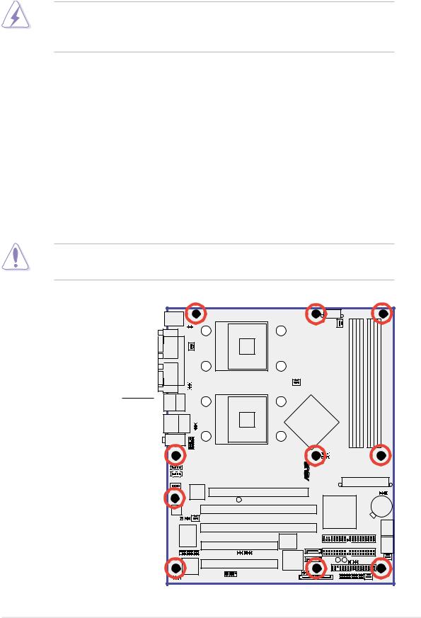
2.2.1 Placement direction
When installing the motherboard, make sure that you place it into the chassis in the correct orientation. The edge with external ports goes to the rear part of the chassis as indicated in the image below.
2.2.2 Screw holes
Place ten (10) screws into the holes indicated by solid black circles to secure the motherboard to the chassis.
Do not overtighten the screws! Doing so may damage the motherboard.
Place this side towards the rear of the chassis
NCCH-DL |
® |
ASUS NCCH-DL motherboard |
2-3 |

2.2.3 Support plates for motherboard
For additional protection from motherboard breakage due to the weight of the CPU heatsinks, your motherboard package comes with a CPU heatsink support kit that consists of:
•2 x metal support plates
•1 x contour sheet
•3 different sets of metal nuts and rubber pads for varied chassis standoffs (each set contains 8 metal nuts and 2 rubber pads)
To install the support plates:
1.Open and lay your system chassis flat on a stable surface, then place the motherboard standoffs on the holes as shown.
Standoff
2.Align the holes of the contour sheet with the standoffs on the base of the chassis. Press the sheet flat making sure that it is completely affixed to the chassis.
The contour sheet fits in only one orientation. Make sure that the hole located about
1 cm from the corner matches the standoff beside the power supply cage.
Standoff beside power supply cage
3.Determine the height of the standoffs on your chassis, and select the appropriate set of metal nuts and rubber pads from your package.
Use a nut size that is slightly lower than the standoffs on your chassis.
2-4 |
Chapter 2: Hardware information |

4.Use a plier to attach four nuts to the bolts on the metal support plate.
5.Align a rubber pad to the rectagular mark on the center of the plate, then press to attach.
6.Remove the adhesive label underneath a plate.
ASUS NCCH-DL motherboard |
2-5 |

7.Carefully align and place the plate on a rectangular cut on the contour sheet.
Make sure that the metal support plates fit perfectly to the rectangular cuts on the contour sheet; otherwise, the CPU heatsink screws would not align to the metal nuts.
8.Repeat steps 4 and 7 to prepare and install the second plate.
8.Remove the contour sheet from the chassis.
2-6 |
Chapter 2: Hardware information |

The support plates appear as shown when installed.
9.Install the motherboard with the external I/O ports toward the chassis rear panel. The CPU sockets should be right on top of the support plates.
Heatsink hole matched to a nut on the support plate
Make sure that the CPU heatsink holes on the motherboard perfectly match the metal nuts on the support plates; otherwise, you can not install the CPU heatsinks properly.
10.Secure the motherboard with 10 screws. Refer to section “2.2.2 Screw holes” for illustration.
ASUS NCCH-DL motherboard |
2-7 |

2.2.4 Motherboard layout
|
|
|
|
25cm (9.8in) |
|
|
|
|
PS/2KBMS |
|
|
ATX12V1 |
|
|
|
|
|
|
|
|
|
|
|
|
||
T: Mouse |
|
|
|
|
|
|
|
|
B: Keyboard |
|
|
|
|
|
|
|
|
|
|
KBPWR1 |
604 |
REAR_FAN1 |
|
|
|
|
COM1 |
|
|
|
|
|
|
||
|
|
|
|
|
|
|
|
|
|
PARALLELPORT |
CPU_FAN1 |
mPGA |
|
module)pin-184 |
module)pin-184 |
module)pin-184 |
module)pin-184 |
|
FM_CPU1 |
|
||||||
|
|
|
|
CPU1 |
|
|
|
|
|
|
|
|
CPU_FAN2 |
bit, |
bit, |
bit, |
bit, |
|
|
|
|
(72 |
(72 |
(72 |
(72 |
|
COM2 |
|
USBPW12 |
|
FM_CPU2 |
||||
|
604mPGA |
DIMM1DDR |
DIMM2DDR |
DIMM3DDR |
DIMM4DDR |
|||
T:USB4Bottom: Top: |
|
|
||||||
B:USB3 1394 |
|
|
|
|
|
|
|
|
USB2.0 |
Top: |
|
|
Intel |
|
|
|
|
T: USB1 |
|
|
82875P |
|
|
|
|
|
RJ-45 |
|
|
|
|
|
|||
B: USB2 |
|
USBPW34 |
|
Canterwood |
|
|
|
|
|
|
|
|
|
|
|
||
Top:Line In |
|
|
|
CPU2 |
|
|
|
|
Center:Line Out |
|
|
|
|
|
|
||
Below:Mic In |
|
|
|
|
|
|
|
|
|
|
|
|
|
|
|
|
|
|
|
FP_AUDIO1 |
|
|
|
|
|
|
|
|
|
|
|
|
|
DL- |
|
|
|
|
|
|
|
|
|
|
|
|
|
|
|
|
|
|
|
|
|
|
|
|
|
|
|
|
||||||||
|
|
|
|
|
|
|
|
|
|
|
|
|
|
|
|
|
|
|
|
|
|
|
|
|
|
|
|
|
|
|
|
® |
|
|
|
|
|
|
J1 |
|
|
|
|
|
|
|
|
|
|
|
|
|
|
|
|
|
|
||||
|
|
|
|
|
|
|
AUX1 |
|
|
|
|
|
|
|
|
|
|
|
|
|
NCCH |
|
|
|
|
|
|
|
|
|
|
|
|
|
|
|
|
|
|
|
|
|
|
|
|
|
|
|
|
||||||||||||
|
|
|
|
|
|
|
|
|
|
|
|
|
|
|
|
|
|
|
|
|
|
|
|
|
|
|
|
|
|
|
|
|
|
|
|
|
|
|
|
|
|
|
|
|
|
|
|||||||||||||||
|
|
|
|
|
|
|
CD1 |
|
|
|
|
|
|
|
|
|
|
|
|
|
|
|
|
|
|
|
|
|
|
|
|
|
|
|
|
|
|
|
|
|
|
|
|
|
|
|
|
|
|
|
|
|
|
|
|
|
|
|
|||
|
|
|
|
|
|
|
|
|
|
|
|
|
|
|
|
|
|
|
|
|
|
|
|
|
|
|
|
|
|
|
|
|
|
|
|
|
|
|
|
|
|
|
|
|
|
|
|
|
|
|
|
|
|
|
|
|
|
||||
|
|
|
|
|
|
|
|
|
|
|
|
|
|
|
|
|
|
|
|
|
|
|
|
|
|
|
|
|
|
|
|
|
|
|
|
|
|
|
|
|
|
|
|
|
|
|
|
ATXPWR1 |
|
|
|||||||||||
|
|
|
|
|
|
|
|
|
|
|
|
|
|
Intel |
|
|
|
|
|
|
|
|
|
|
|
|
|
|
|
|
|
|
|
|
|
|
|
|
|
|
|
|
|
|
|
|
|
|
|
|
|
|
|
|
|
|
|
|
|||
MODEM1 |
|
|
82547GI |
|
Accelerated Graphics Port (AGP8X1) |
|
|
|
|
|
|
|
|
|
|
|
|
|
|
|
|
|
|
|
|
|
|
|
|
|
|
|
|
||||||||||||||||||||||||||||
|
|
|
|
|
|
|
|
|
|
|
|
|
Gigabit |
|
|
|
|
|
|
|
|
|
|
|
|
|
|
|
|
|
|
|
|
|
|
CLRTC1 |
|
|
|
||||||||||||||||||||||
|
|
|
|
|
|
|
|
|
|
|
|
|
Ethernet |
|
|
|
|
|
|
|
|
|
|
|
|
|
|
|
|
|
|
|
|
|
|
|
|
|
|
|
|
|
|
|
|
|
|
|
|
|
|
|
|
|
|
|
|
||||
|
|
|
|
|
|
|
|
|
|
|
|
|
|
|
WARN1 |
|
|
|
|
|
|
|
|
|
|
|
|
|
|
|
|
|
|
|
|
|
|
|
|
|
|
|
|
CR2032 3V |
|||||||||||||||||
|
|
|
|
|
|
|
|
|
|
|
|
|
|
|
|
|
|
|
|
|
|
|
|
|
|
|
|
|
|
|
|
|
|
|
|
|
|
|
|
|
|
|
|
|
|
|
|
|
|
|
|||||||||||
|
|
|
|
|
|
|
|
|
|
|
|
|
|
|
|
|
|
|
|
|
|
|
|
|
|
|
|
|
|
|
|
|
|
|
|
|
|
|
|
|
|
|
|
|
|
|
|||||||||||||||
|
|
|
|
|
|
|
|
|
|
|
|
|
|
|
|
|
|
|
|
|
|
|
|
|
|
|
|
|
|
|
|
|
|
|
|
|
|
|
|
|
|
|
|
|
|
|
|
|
|
|
|
|
|
|
|
|
|||||
|
|
|
|
|
|
|
|
|
|
|
|
|
|
|
|
|
|
|
|
PCIX1 (64-bit, 66MHz 3V) |
|
|
|
|
|
|
|
|
|
Intel |
|
|
|
|
|
|
|
|
|
|
Lithium Cell |
||||||||||||||||||||
|
|
AD1980 |
|
|
|
|
|
|
|
|
|
|
|
|
|
|
|
|
|
|
|
|
|
|
|
|
|
|
|
|
|
CMOS Power |
|||||||||||||||||||||||||||||
|
|
|
|
|
|
|
|
|
|
|
|
|
|
|
|
|
|
|
|
|
|
|
|
|
|
|
|
|
|
|
|
|
|
|
|
|
|
|
|
Hance Rapids |
|
|
|
|
|
|
|
|
|
|
|
||||||||||
|
|
|
|
|
|
|
|
|
|
|
|
|
|
|
|
|
REAR_FAN2 |
|
|
|
|
|
|
|
|
|
|
|
(South Bridge) |
|
|
|
|
|
|
|
|
|
|
|
|||||||||||||||||||||
|
|
|
SPDIF_OUT1 |
|
|
|
|
|
|
|
|
|
|
|
|
|
|
|
|
|
|
|
|
|
|
|
|
|
|
|
|
|
|
|
|
|
|
|
|
|
|
|
|
|
|
|
|
|
|
|
|
||||||||||
|
|
|
|
|
|
Super |
I/O |
|
|
|
|
|
PCIX2 (64-bit, 66MHz 3V) |
|
|
|
|
|
|
|
|
|
|
|
|
|
|
|
|
|
|
|
|
|
|
|
|
|
|
SATA1 |
|||||||||||||||||||||
|
|
|
|
|
|
|
|
|
|
|
|
|
|
|
|
|
|
|
4Mbit Flash BIOS |
|
|
|
|
|
|
|
|
|
|
|
|
|
|
|
|
|
|
|
|
PRI_IDE1 |
SATA2 |
||||||||||||||||||||
|
|
|
|
|
|
|
|
|
|
|
|
|
|
|
|
|
|
|
|
|
|
|
|
|
|
|
|
|
|
|
|
|
|
|
|
|
|
|
|
|
|
|
|
|
|
|
|
|
|
|
|
|
|
|
|
||||||
|
|
|
|
|
|
|
|
|
|
|
|
|
|
|
|
|
|
|
|
|
|
|
|
|
|
|
|
|
|
|
|
|
|
|
|
|
|
|
|
|
|
|
|
|
|
|
|
|
|
|
|
|
|
|
|
|
|
|
|
|
|
|
|
|
|
|
|
|
|
|
|
|
|
|
|
|
|
|
|
|
|
|
|
|
|
|
|
|
|
|
|
|
|
|
|
|
|
|
|
|
|
|
|
|
|
|
|
|
|
|
|
|
|
|
|
|
|
|
|
|
|
|
|
|
|
|
|
|
|
|
|
|
|
|
|
|
|
|
|
|
|
|
PCI1 (32-bit, 33MHz 5V) |
|
|
|
|
|
|
|
SATA_RAID4 |
|
|
|
|
|
|
|
|
|
SEC_IDE1 |
|
|
||||||||||||||||||||||
|
|
|
|
|
|
|
|
|
|
|
|
|
|
|
|
|
|
|
|
|
|
|
|
|
|
|
|
|
|
|
|
|
|
|
|||||||||||||||||||||||||||
|
|
|
|
|
|
|
|
|
|
|
|
|
|
|
|
|
|
|
|
|
|
|
|
|
|
|
|
|
|
|
|
|
|
|
|
|
|
|
|
|
|
|
|
|
|
|
|
|
|
|
|
|
|
|
|
|
|
|
|
|
|
GAME1 |
|
|
|
|
|
|
|
|
|
|
|
|
|
|
|
|
|
|
|
|
|
BPSMB1 |
|
Promise |
|
|
|
|
|
|
|
|
|
|
|
|
|
|
|
|
|
|
|
|
|
|
|
|
|
|
|
|
|||||||||
|
|
|
|
|
|
|
|
|
|
|
|
|
|
|
|
|
|
|
|
|
|
|
|
|
|
|
|
|
|
|
|
|
|
|
|
|
|
|
|
|
|
|
|
|
|
|
|
|
|
|
|
|
|
|
|
|
|
||||
|
|
|
|
|
|
|
|
|
|
|
|
|
|
|
|
|
|
|
|
|
|
|
|
|
|
|
|
|
|
|
|
|
|
SB_PWR1 |
|
|
|
WARN_CPU1 |
|
|
|||||||||||||||||||||
|
|
|
|
|
|
|
|
|
|
|
|
TI |
|
|
|
PCI2 (32-bit, 33MHz 5V) |
|
|
PDC20319 |
|
SATA_RAID3 |
|
|
|
|
|
|
|
|
|
|
|
CHASSIS1 FRNT_FAN2 |
||||||||||||||||||||||||||||
|
|
|
|
|
|
TSB43AB22A |
|
|
|
|
|
|
|
|
|
|
|
|
|
|
|
|
|
|
|
|
|
|
|
|
|
|
|
|
|
|
|
|
|
|
|
|
|
|
|
|
|
FLOPPY1 |
|||||||||||||
|
|
|
|
|
|
|
|
|
|
|
|
|
|
|
|
|
|
|
|
|
|
|
|
|
|
|
|
|
|
|
|
|
|
|
|
|
|
|
|
|
|
|
|
|
|
|
|
||||||||||||||
|
|
|
|
|
|
|
|
|
|
|
|
|
|
|
|
|
|
|
|
|
|
|
|
|
|
|
|
|
|
RAID_EN1 |
|
|
|
|
|
|
|
IDE |
|
|
|
|
|
|
|
|
|
|
|
|
|
|
|
|
|||||||
|
|
|
|
|
|
|
|
|
|
|
|
|
|
|
|
|
|
|
|
|
|
|
|
|
|
|
|
|
|
|
|
|
|
|
|
|
_LED1 |
|
|
|
|
|
|
|
|
|
|
|
|
|
|
|
|
|
|
||||||
|
|
|
|
|
|
|
|
|
|
|
|
|
|
|
|
|
|
|
|
|
|
|
|
|
|
|
|
|
|
|
|
|
|
|
|
|
|
|
|
|
|
|
|
|
|
|
|
|
|
|
|
|
|
|
|
|
|
|
|
|
|
|
1394_EN1 |
|
|
|
|
|
|
|
|
IEEE1394_1 |
|
|
|
|
|
|
|
|
|
|
|
|
|
|
|
|
|
|
|
|
|
|
|
|
|
|
|
|
|
|
|
|
|
||||||||||||||||||
|
|
|
|
|
|
|
|
|
|
|
|
|
|
|
|
|
|
|
|
|
|
|
|
|
|
|
|
|
|
|
|
SATA_RAID1 SATA_RAID2 |
PANEL1 |
|
|
|
FRNT_FAN1 |
|
|
||||||||||||||||||||||
|
|
|
|
|
|
|
|
|
|
|
|
|
|
|
|
|
|
|
|
|
|
|
|
|
|
|
|
|
|
|
|
|
|
|
|
|
|
|
|
|
|
|
|
||||||||||||||||||
30.5cm (12in)
2-8 |
Chapter 2: Hardware information |

2.2.5 |
Layout contents |
|
|
|
|
Sockets/Slots |
Page |
|
|
|
|
1. |
CPU sockets |
2-11 |
2. |
DDR DIMM sockets |
2-15 |
3. |
PCI/PCI-X slots |
2-20 |
4. |
AGP Pro/8X slot |
2-20 |
|
|
|
Jumpers |
|
|
1. |
Keyboard power (3-pin KBPWR1) |
2-21 |
2. |
RAID controller setting (3-pin RAID_EN1) |
2-21 |
3. |
USB device wake-up (3-pin USBPW12, USBPW34) |
2-22 |
4. |
CPU external frequency selection (3-pin J1) |
2-22 |
5. |
IEEE 1394 setting (3-pin 1394_EN) |
2-23 |
6. |
CPU fan pin selection (3-pin FM_CPU1, FM_CPU2) |
2-24 |
7. |
Clear RTC RAM (3-pin CLRTC1) |
2-24 |
|
|
|
Rear panel connectors |
|
|
|
|
|
1. |
PS/2 mouse port |
2-25 |
2. |
Parallel port |
2-25 |
3. |
IEEE 1394 port |
2-25 |
4. |
LAN port (RJ-45) |
2-25 |
5. |
Line In port |
2-25 |
6. |
Line Out port |
2-25 |
7. |
Microphone port |
2-25 |
8. |
USB 2.0 ports 3 and 4 |
2-26 |
9. |
USB 2.0 ports 1 and 2 |
2-26 |
10. |
Serial ports |
2-26 |
11. |
PS/2 keyboard port |
2-26 |
|
|
|
Internal connectors |
|
|
|
|
|
1. |
Floppy disk drive connector (34-1 pin FLOPPY1) |
2-27 |
2. |
Serial ATA connectors (7-pin SATA1, SATA2) |
2-27 |
3. |
IDE connectors (40-1 pin PRI_IDE[blue], SEC_IDE [black) |
2-28 |
4. |
GAME/MIDI connector (16-1 pin GAME1) |
2-28 |
5. |
IEEE 1394 connector (10-1 pin IE1394_1) |
2-29 |
6. |
Chassis intrusion connector (4-1 pin CHASSIS1) |
2-29 |
7. |
Serial ATA RAID connectors (7-pin SATA_RAID1/2) |
2-30 |
8. |
Backplane SMBus connector (6-1 pin BPSMB1) |
2-30 |
9. |
Power connectors (24-pin ATXPWR1, 8-pin ATX12V1) |
2-31 |
10. |
Hard disk activity LED connector (2-pin IDELED1) |
2-31 |
|
|
|
ASUS NCCH-DL motherboard |
2-9 |

Internal connectors (continued)
11. |
Front panel audio connector (10-1 pin FP_AUDIO1) |
2-32 |
12. |
Internal audio connectors (4-pin CD1, AUX1, MODEM1) |
2-32 |
13. |
CPU and system fan connectors |
|
|
(3-pin CPU_FAN1/2, REAR_FAN1/2, FRNT_FAN1/2) |
2-33 |
14. |
System panel connector (20-pin PANEL) |
2-33 |
|
- System Power LED (3-pin PLED) |
2-34 |
|
- Message LED (2-pin MLED) |
2-34 |
|
- System warning speaker (4-pin SPKR) |
2-34 |
|
- Hard disk activity (2-pin HD_LED) |
2-34 |
|
- Power switch / Soft-off switch (2-pin PWR_SW) |
2-34 |
|
- Reset switch (2-pin RESET) |
2-34 |
|
- System Management Interrupt (2-pin SMI) |
2-34 |
2-10 |
Chapter 2: Hardware information |
 Loading...