


English
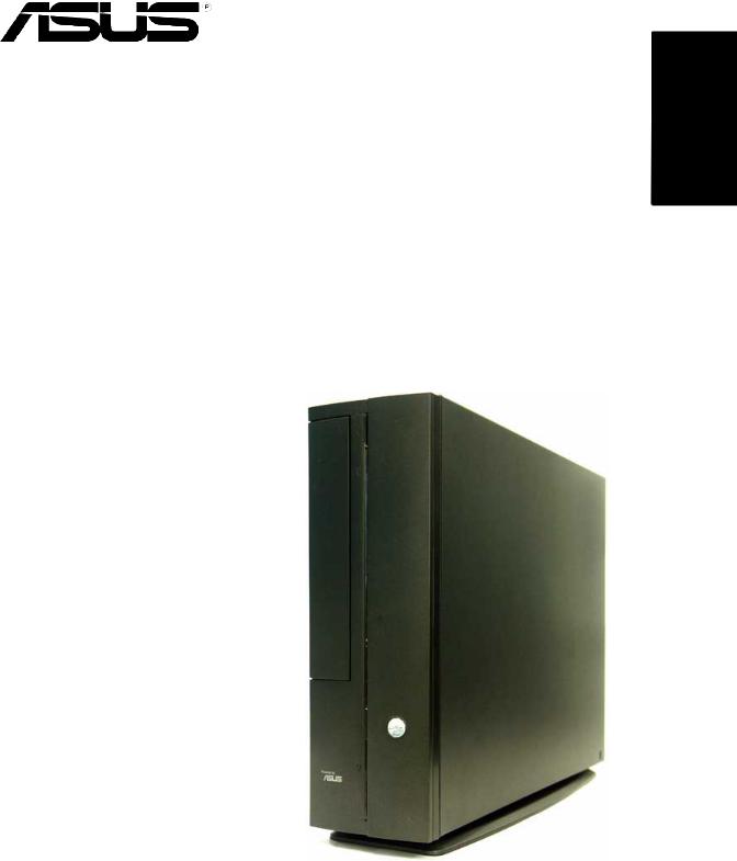
Pundit P1-AH1
Barebone System
Quick Installation Guide
English
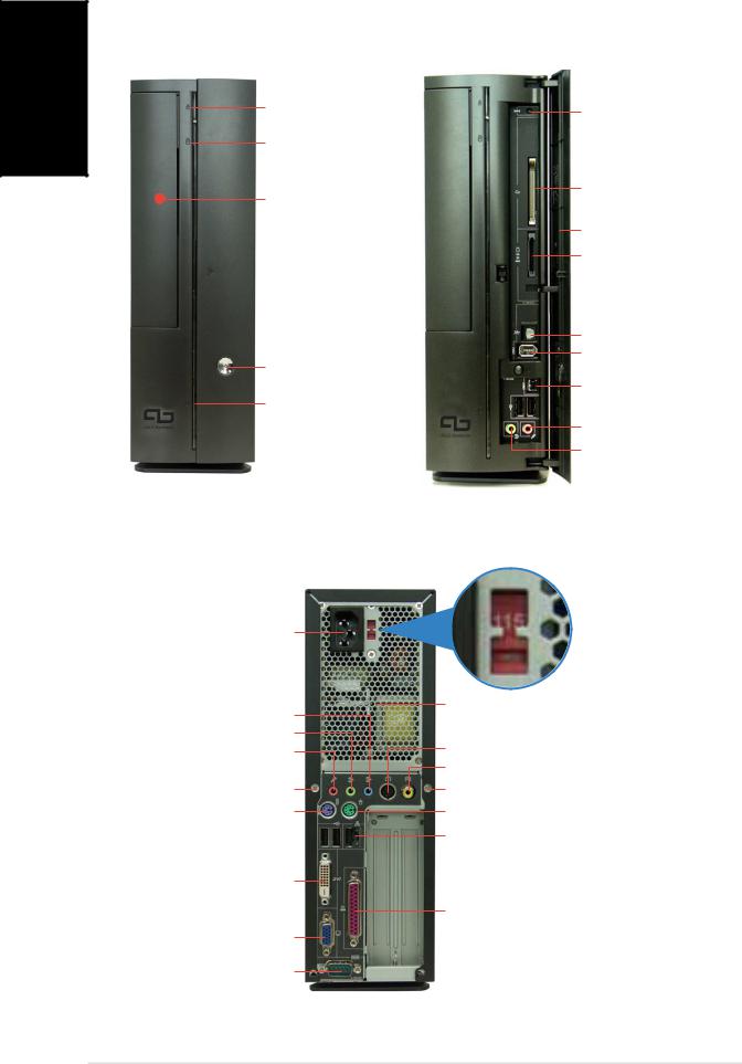
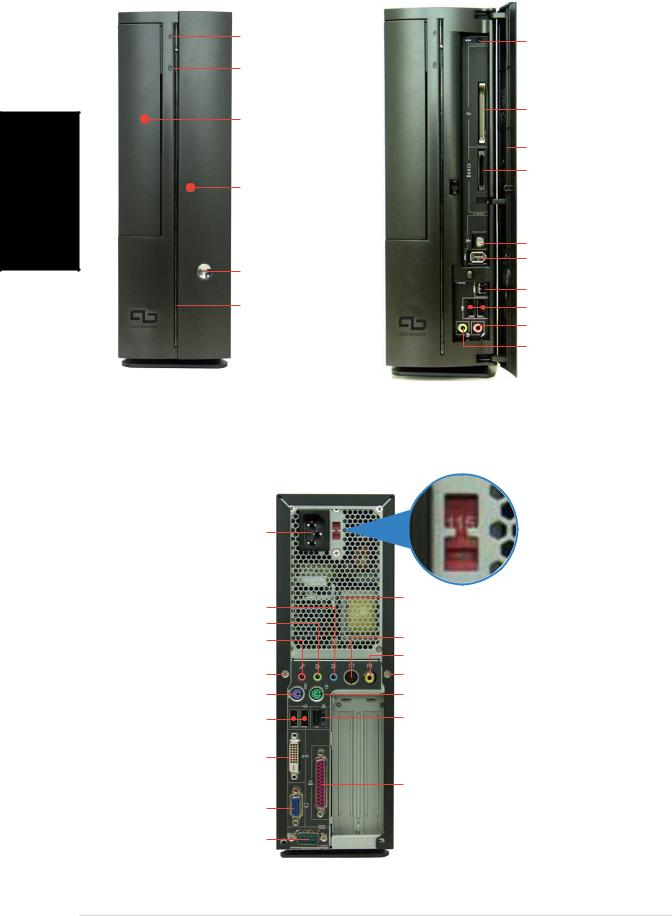
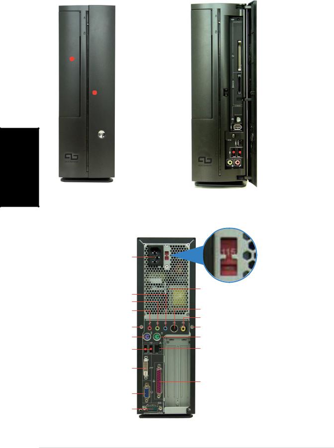
Front panel features
Close |
Open |
Optical drive ejec t button
HD D LED
Optical drive ba y cover
 P r e s s to open the front p a n e l c o v e r
Powe r button
Powe r LED
Rese t button
CompactFlash® car d slot
Front panel cover 3-in-1 card reader*
S/PDI F Ou t port
6-pin IEEE 1394 port
4-pin IEEE 1394 port 
 US B 2 . 0 ports
Headphon e port Microphon e port
* Memory Stick®/Pro™, SecureDigital™,
MultiMediaCard
Rear panel features
Power connector
Lin e I n port
Line Out port
Microphone port
Cove r screw
PS/2 keyboard port
USB 2.0 ports 
DV I Ou t port
VG A port
Seria l port
Voltage selector*
Power supply air vents
S-Video Out port
T V Ou t port
Cove r screw
PS/2 mouse port
LAN (RJ-45) port

 PCI slot metal brackets
Paralle l port
* The system’s power supply unit has a
115 V/230 V voltage selector switch located near the power connector. Use this switch to select the correct system input voltage according to the voltage supply in your area.
2 |
Quick installation guide |
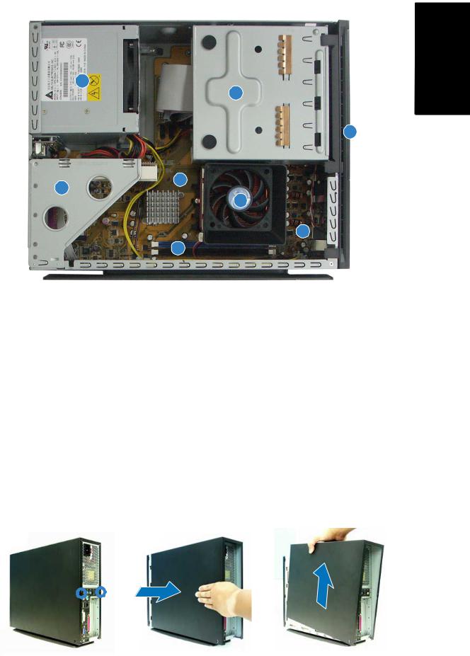
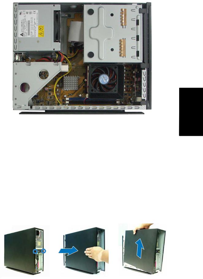
Internal components
3
1
2
5
4
8
 7
7
6
1. 5.25-inch optical drive and |
5. |
ASUS motherboard |
|
|
3.5 inch hard disk drive cage |
6. |
DIMM sockets |
2. |
Front panel cover |
7. |
Socket for 939-pin processor |
3. |
Power supply unit |
|
(under the CPU fan and |
4. |
PCI card riser bracket |
|
heatsink assembly) |
|
(connected to the |
8. |
CPU fan and heatsink assembly |
|
motherboard PCI slot) |
|
|
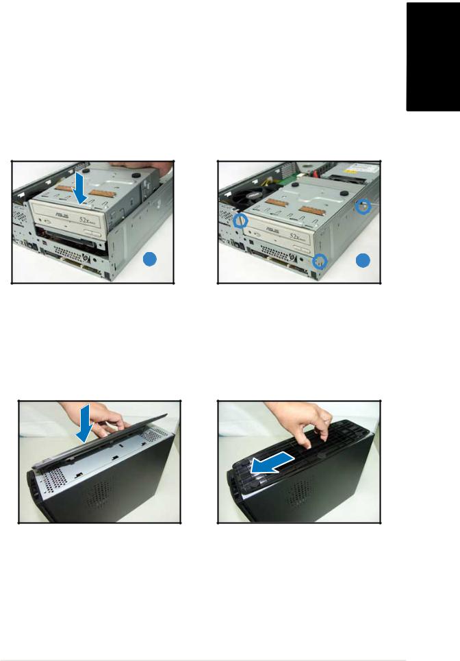
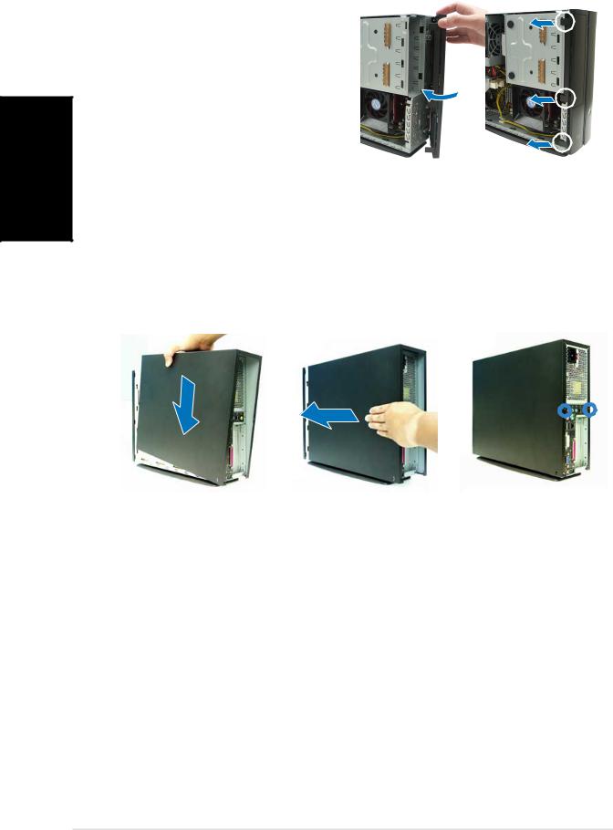
Removing the cover
1.Remove the cover screws. Keep the screws for later use.
2.Pull the cover slightly toward the rear panel.
3.Lift the cover, then set aside.
1 |
|
|
2 |
|
|
3 |
|
|
|
|
|
|
|
|
|
|
|
|
|
|
|
|
|
|
|
|
English
Quick installation guide |
3 |

English
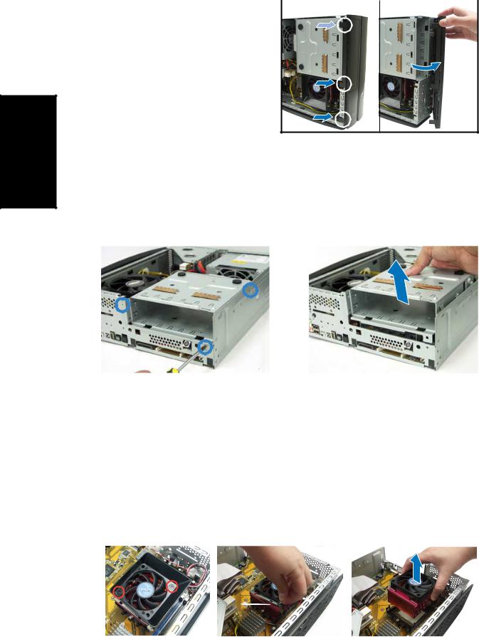
Removing the front panel cover
1. Lift the front panel cover |
|
1 |
|
2 |
|
hooks outward. |
|
|
|
|
|
2.Carefully remove the front panel cover, then set it aside.
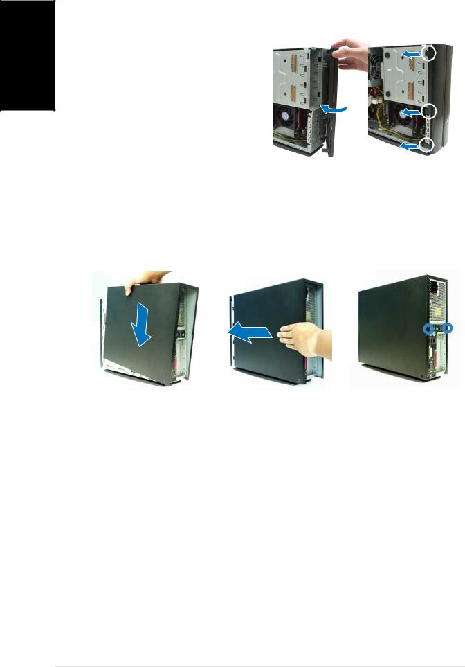
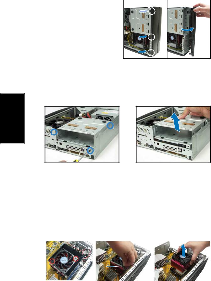
Removing the storage drive assembly
1.Lay the system on its side, then locate and remove three storage drive assembly screws.
2.Lift the storage drive assembly, then set aside.
Removing the CPU fan and heatsink
1.Disconnect the CPU fan cable.
2.Remove two screws securing the blower to the CPU fan. Set the blower aside.
3.Unhook and slide out the metal clips that secure the fan and heatsink assembly to the retention module.
4.Lift the CPU fan and heatsink assembly, then set aside.
|
2 |
|
|
3 |
|
|
4 |
|
|
|
|
|
|
|
|
|
|
|
|
|
|
|
|
|
|
|
4 |
Quick installation guide |
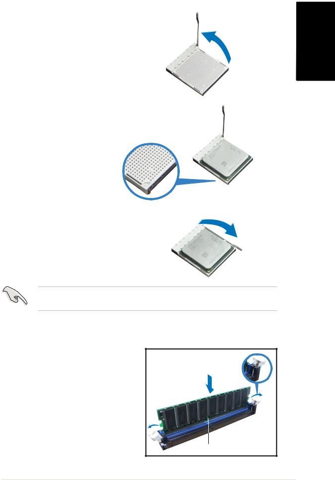
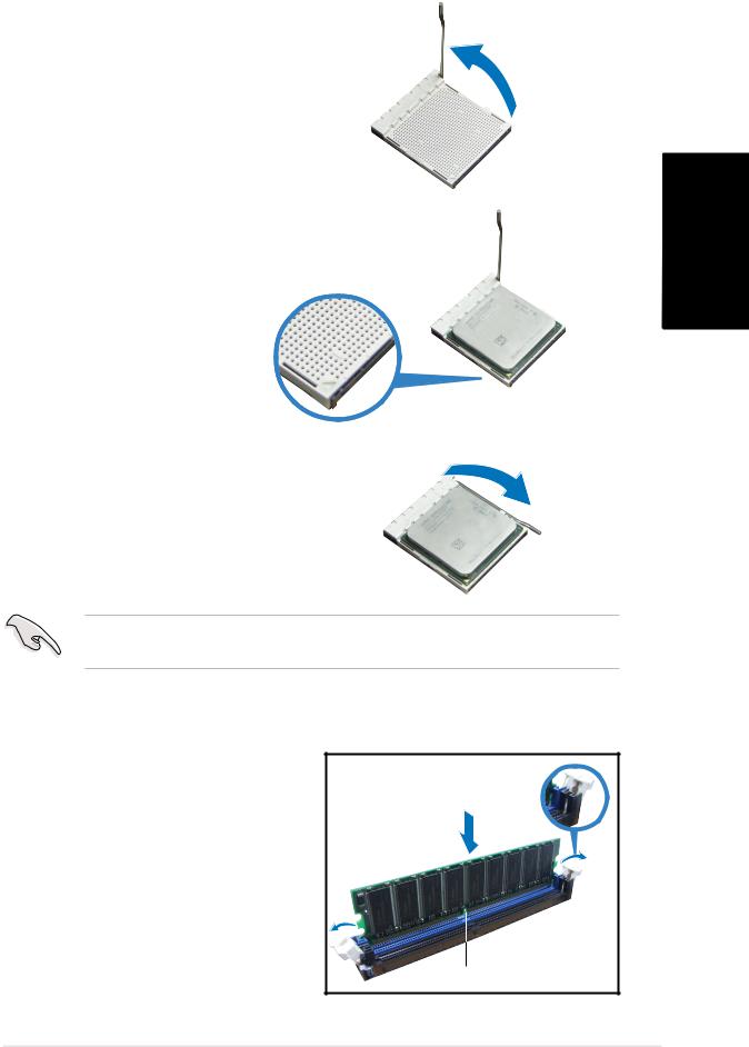
Installing the CPU
1.Press the CPU socket lever sideways, then lift it up to a 90º-100º angle.
2.Match the gold triangle on the CPU with the small triangle on the socket. Insert the CPU into the socket until it fits in place.
3.Push down the socket lever to secure the CPU.
IMPORTANT! Make sure to install the CPU fan, blower, and heatsink assembly on top of the installed CPU.
Installing a DIMM
1.Locate the DIMM sockets in the motherboard.
2.Unlock a DIMM socket by pressing the retaining clips outward.
3.Align a DIMM on the socket such that the notch on the DIMM matches the break on the socket.
Unlocked retaining clip
DD R DIM M notch
English
Quick installation guide |
5 |
English
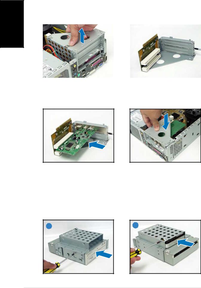
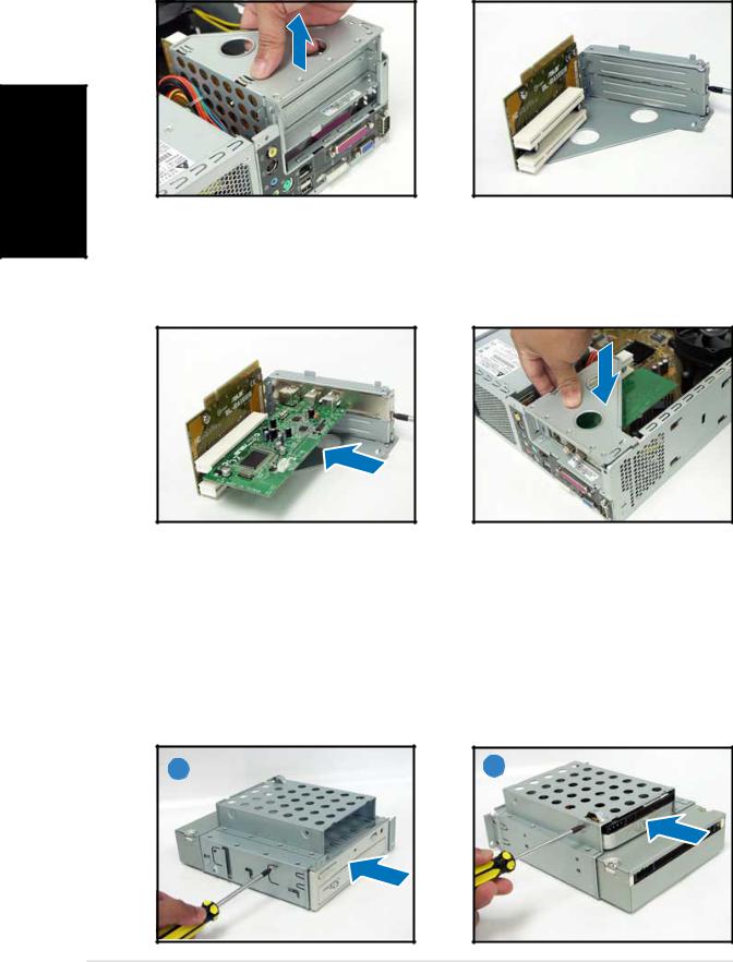
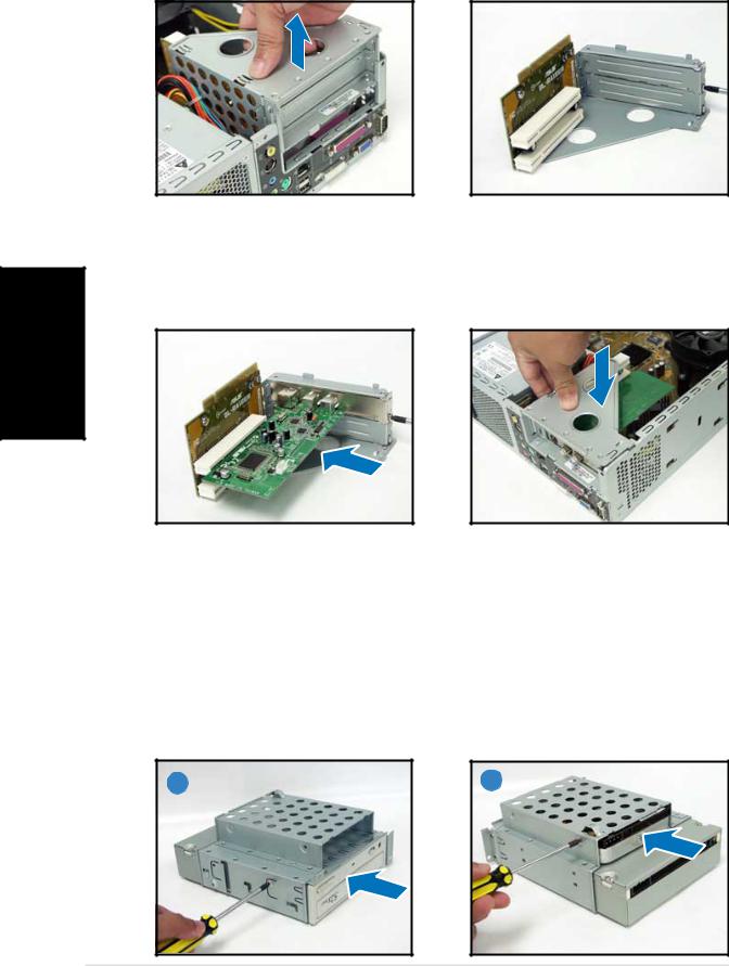
Installing an expansion card
1. Lift the PCI riser card |
2. Remove the metal cover |
||
|
assembly to remove. |
|
opposite the slot that you |
|
|
|
intend to use. |
|
|
|
|
|
|
|
|
3.Insert the card connector to the slot, then press the card firmly until it fits in place.
Secure the card with a screw.
4.Reinstall the PCI riser card assembly. Make sure that the riser card connector sits properly on the motherboard PCI slot.
Installing optical and storage drives
1.Turn the storage drive assembly upside down with the 3.5-inch bay on top of the 5.25-inch bay.
2.Insert the optical drive upside down to the 5.25-inch bay, then secure it with two screws on both sides.
3.Turn the storage drive assembly, insert the hard disk drive upside down to the 3.5-inch bay, then secure it with two screws on both sides.
2 |
3 |
6 |
Quick installation guide |
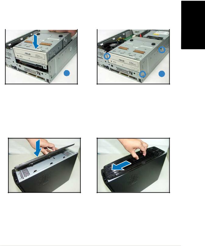
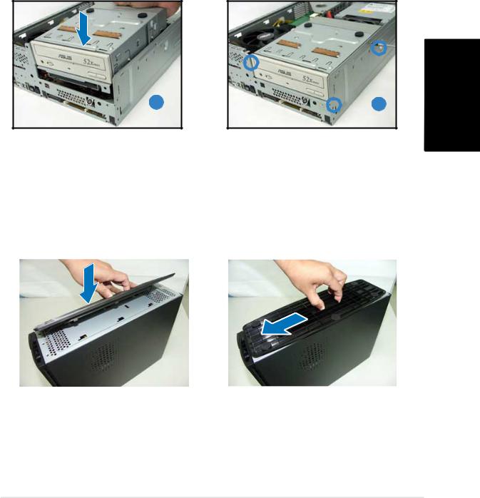
Reinstalling the storage drive assembly
Before reinstalling the storage drive assembly, connect the IDE and power plugs to the IDE and power connectors at the back of the drives.
1.Connect the black plug of the IDE cable to the optical drive, then the gray plug to the hard disk drive.
2.Connect the 4-pin power plugs to the power connectors at the back of the drives.
3.Install the storage drive assembly to the chassis.
4.Secure the storage drive assembly with three screws.
English
3 |
4 |
Installing the foot stand
1.Match the foot stand hooks to the holes on the chassis.
2.Pull the foot stand to the direction of the arrow until the lock clicks in place.
To remove the foot stand, lift the lock, then slightly push the foot stand to the direction of the rear panel until it disengages from the chassis.
Quick installation guide |
7 |
English
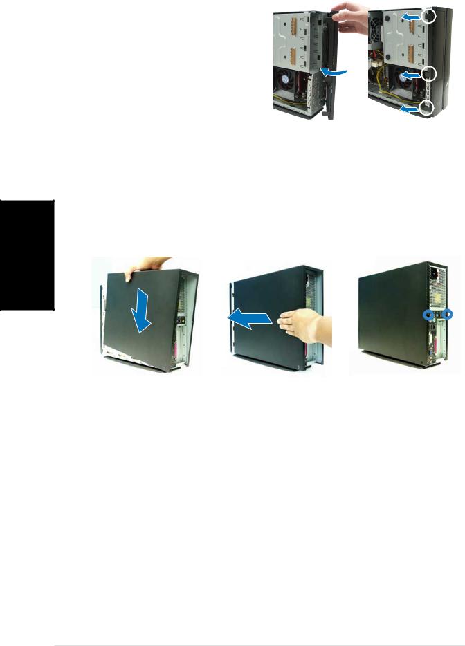
Reinstalling the front panel cover
1. |
Insert the front panel cover |
|
|
|
|
1 |
|
2 |
|
||
|
tabs to the holes at the right |
|
|
|
|
|
|
|
|
|
|
|
side of the chassis, then close. |
|
|
|
|
2. |
Insert the front panel cover |
|
|
|
|
|
hooks to the chassis tabs until |
|
|
|
|
|
the front panel cover fits in |
|
|
|
|
|
place. |
|
|
|
|
|
|
|
|
|
|
Reinstalling the cover
1.Install the cover to the chassis. Make sure the cover tabs fit the chassis rails.
2.Push the cover toward the front panel until it fits in place.
3.Secure the cover with two screws.
1 |
|
|
2 |
|
|
3 |
|
|
|
|
|
|
|
|
|
8 |
Quick installation guide |
Pundit P1-AH1
Système barebone
Guide d’installation rapide
Français
ais çFran
Caractéristiques de la façade
Fermé |
Ouvert |
Bouton d’ejection du lecteur optique
LE D HDD
Capot d e la baie
du lecteur optique
Appuye z pour ouvrir le capot de l a fa ç ade
B o u t o n
d ’alimentation
L E D
d ’alimentation
Bouto n Reset
Slot pour cartes
CompactFlash®
Capot de la fa çade
Lecteur d e carte 3 e n 1*
Por t S/PDI F Out
Port IEEE 1394 6 broches
Port IEEE 1394 4 broches Port s US B 2 . 0
Por t Casque
Por t Microphone
* Memory Stick®/Pro™, SecureDigital™,
MultiMediaCard
Caractéristiques de l’arrière
Connecteur d ’alimentation
Por t Lin e In
Por t Lin e Out
Por t Microphone
Vi s d u capot Port clavier PS/2
Port s US B 2 . 0
Por t DV I Out
Por t VGA
Por t S é rie
Sélecteur de tension*
Trous d’aération de l’alimentation
Por t S -Video Out
Por t T V Out
Vi s d u capot
Por t souri s PS/2
Port LA N (RJ - 45)

 Brackets métalliques des ports PCI Por t parall èle
*L’alimentation du système est équipée d’un sélecteur de tension 115 V/230 V situé près du connecteur d’alimentation. Utilisez cet interrupteur pour choisir la bonne tension d’entrée en fonction des standards utilisés dans votre région.
2 |
Guide d’installation rapide |
Composants internes
3
1
2
5
4
8
 7
7
6
1.Bloc du lecteur optique 5.25’’ et du lecteur de disque dur 3.5’’.
2.Façade
3.Alimentation
4.Bracket du PCI Card Riser
(connecté au slot PCI de la carte mère)
5.Carte mère ASUS
6.Sockets DIMM
7.Socket pour processeur 939 broches (sous l’ensemble dissipateur-ventilateur du CPU)
8.Système de refroidissement du CPU
Enlever le capot
1.Enlevez les deux vis. Conservez les vis pour un usage ultérieur.
2.Tirez légèrement le panneau vers l’arrière.
3.Soulevez le capot, puis basculez-le.
1 |
|
|
2 |
|
|
3 |
|
|
|
|
|
|
|
|
|
|
|
|
|
|
|
|
|
|
|
|
Franç ais
Guide d’installation rapide |
3 |
ais çFran
Retirer le capot de la façade
1. Levez les crochets du capot |
|
1 |
|
2 |
|
avant vers l’extérieur. |
|
|
|
|
|
2.Retirez avec précaution le capot, puis mettez-le de côté.
Retirer l ’ensemble de stockage
1. Posez le système sur le côté, |
2. Soulevez l’ensemble de |
||
|
puis localisez et retirez les |
|
stockage, puis mettez-le de |
|
trois vis de l’ensemble de |
|
côté. |
|
stockage. |
|
|
|
|
|
|
|
|
|
|
Retirez le dissipateur et le ventilateur du CPU
1.Déconnectez le câble de ventilation du CPU.
2.Retirez les deux vis sécurisant les pâles du ventilateur CPU. Mettez les pâles de côté.
3.Déverrouillez et faites glisser les clips en métal sécurisant l’ensemble dissipateurventilateur au module de rétention.
4.Soulevez l’ensemble dissipateur/ventilateur du CPU, puis mettez-le de côté.
|
2 |
|
|
3 |
|
|
4 |
|
|
|
|
|
|
|
|
|
|
|
|
|
|
|
|
|
|
|
4 |
Guide d’installation rapide |
Installer le CPU
1.Pressez sur le levier du socket du CPU , puis soulevez-le dans un angle de 90º-100º.
2.Sécurisez le CPU sur le socket en vous assurant que la marque en forme de triangle doré coincide avec la base du socket.
3.Abaissez le levier du socket pour sécuriser le CPU.
IMPORTANT! Assurez-vous de bien avoir fixer l’ensemble dissipateurventilateur sur le CPU précédemment installé.
Installer un module DIMM
1.Localisez les sockets DIMM de la carte mère.
2.Déverrouillez un socket DIMM en pressant sur les clips de rétention vers l’extérieur.
3.Alignez un module DIMM sur le socket de sorte que l’encoche sur la DIMM corresponde à l’ergot du socket.
Clip de rétention
d é verrouill é
Encoche du DIMM DDR
Franç ais
Guide d’installation rapide |
5 |
Installer une carte d’extension
1.Soulevez l’ensemble PCI Riser Card pour le retirez du châssis.
2.Retirez la protection métallique faisant face au slot que vous désirez utiliser.
ais çFran
3.Insérez le connecteur de la carte dans le slot et pressez jusqu’à ce que la carte soit en place. Sécurisez la carte avec une vis.
4.Réinstallez l’ensemble PCI Riser Card. Assurez-vous que le connecteur de la riser card soit bien connecté au slot PCI de la carte mère.
Installer un lecteur optique ou de stockage
1.Placez l’ensemble de stockage de façon à ce que la baie 3.5” soit au dessus de la baie 5.25”.
2.Insérez le lecteur optique dans la baie 5.25”, puis sécurisez-le avec deux vis de chaque côté.
3.Insérez le disque dur dans la baie 3.5”, puis sécurisez-le avec deux vis de chaque côté.
2 |
3 |
6 |
Guide d’installation rapide |
Réinstaller l’ensemble de stockage
Avant de réinstaller l’ensemble de stockage, connectez les prises IDE et d’alimentation aux connecteurs IDE et d’alimentation situés à l’arrière des lecteurs.
1. |
Connectez la prise noire du câble IDE au lecteur optique, puis la prise |
|
|||
|
grise au disque dur. |
|
|||
2. |
Connectez la prise d’alimentation 4 broches aux connecteurs |
|
|||
|
d’alimentation situés à l’arrière des lecteurs. |
|
|||
3. |
Installez l’ensemble de stockage sur le châssis. |
ais |
|||
4. |
Sécurisez l’ensemble de stockage avec trois vis. |
||||
Franç |
|||||
|
|
|
|
||
|
|
|
|
||
3 |
4 |
Installer le pied de support
1.Faites correspondre les crochets du pied de support aux ouvertures sur le châssis.
2.Tirez le pied de support dans la direction de la flèche jusqu’à ce qu’il soit bien en place.
Pour retirer le pied de support, soulevez le verrou, puis poussez délicatement le pied de support jusqu’à ce qu’il se désengage du châssis.
Guide d’installation rapide |
7 |
ais çFran
Réinstaller le capot de la façade
1. |
Insérez les onglets du capot |
1 |
|
2 |
|
|
dans les ouvertures situées à |
|
|
|
|
|
droite du châssis, puis |
|
|
|
|
|
refermez-le. |
|
|
|
|
2. |
Insérez les crochets du capot |
|
|
|
|
|
de la façade dans les onglets |
|
|
|
|
|
du châssis jusqu’à ce que le |
|
|
|
|
|
capot soit bien en place. |
|
|
|
|
|
|
|
|
|
|
Réinstaller le panneau
1.Installer le panneau sur le châssis en vous assurant que les onglets du panneau soient bien alignés sur les rails du châssis.
2.Poussez le panneau vers l’avant jusqu’à ce qu’il soit bien en place.
3.Sécurisez le panneau avec deux vis.
1 |
|
|
2 |
|
|
3 |
|
|
|
|
|
|
|
|
|
8 |
Guide d’installation rapide |
Pundit P1-AH1
Barebone Systeme
Schnellinstallationsanleitung
Deutsch
Deutsch
Frontseite
|
|
|
geschlossen |
offen |
|||||||||
|
|
|
|
|
Auswurftaste |
|
|
||||||
|
|
|
|
|
de s optischen |
|
Reset - Schalter |
||||||
|
|
|
|
|
|
|
|
|
|
|
|
|
|
|
|
|
|
|
Laufwerkes |
|
|||||||
|
|
|
|
|
|
|
|||||||
|
|
|
|
|
HDD - LED |
|
CompactFlash® - |
||||||
|
|
|
|
|
|
||||||||
|
|
|
|
|
Schubladenabdeckung |
|
|
||||||
|
|
|
|
|
|
|
Kartensteckplatz |
||||||
|
|
|
|
|
des optischen |
|
|||||||
|
|
|
|
|
|||||||||
|
|
|
|
|
|
|
|||||||
|
|
|
|
|
Laufwerkes |
|
Frontabdeckung |
||||||
|
|
|
|
|
|
|
|
|
|
|
|
|
|
|
|
|
|
|
|
|
|
|
|
|
|
|
|
|
|
|
|
|
Zu m öffne n der |
|
|
3-in-1 Kartenleser* |
|||||
|
|
|
|
|
|
|
|||||||
|
|
|
|
|
Frontabdeckung |
|
|
||||||
|
|
|
|
|
|
|
|||||||
|
|
|
|
|
bitt e hier |
|
|
||||||
|
|
|
|
|
dr ü cken |
|
|
||||||
|
|
|
|
|
|
|
|
|
|
|
|
|
S/PDIF - Ausgang |
|
|
|
|
|
|
|
|
|
|
|
|
|
|
|
|
|
|
|
|
|
|
|
|
|
|
|
6 -Pin-IEEE-1394- Port |
|
|
|
|
|
Stromschalter |
|
|||||||
|
|
|
|
|
|
4-Pin-IEEE-1394- Port |
|||||||
|
|
|
|
|
|
||||||||
|
|
|
|
|
Betriebs - LED |
|
|
|
|
|
|
||
|
|
|
|
|
|
|
|
|
|
|
|||
|
|
|
|
|
|
|
|
|
|
|
USB 2.0-Anschlüsse |
||
|
|
|
|
|
|||||||||
|
|
|
|
|
|
|
|
|
|
|
|||
|
|
|
|
|
|
|
|
|
|
|
|
|
Kopfhöreranschluss |
|
|
|
|
|
|
|
|
|
|
|
|
|
|
|
|
|
|
|
|
|
|
|
|
|
|
|
Mikrofonanschluss |
|
|
|
|
|
|
|
|
|
|
|
|
|
|
Rückseite
Stromanschluss
Line In-Anschluss
Line Out-Anschluss
Mikrofonanschluss
Abdeckungsschraube
PS/2-Tastaturanschluss
USB 2.0-Anschlüsse
DVI - Ausgang
VGA - Anschluss
Serieller Anschluss
*Memory Stick®/Pro™, SecureDigital™, MultiMediaCard
Spannungsschalter*
Netzteill üfter
S-Video-Ausgang
TV - Ausgang
Abdeckungsschraube
PS/2-Mausanschluss
LAN (RJ-45)-Anschluss

 PCI-Steckplatz-Metallblenden
Paralleler Anschluss
* Das Netzteil ist mit einem 115V/230VSpannungsschalter neben dem Stromanschluss ausgestattet. Verwenden Sie diesen Schalter, um die passende Systemeingangsspannung entsprechend Ihrem Stromversorgungssystem in Ihrer Region auszuwählen.
2 |
Schnellinstallationsanleitung |
Interne Komponenten
1.Halterung für optisches Laufwerk 5.25-Zoll und 3.5 Zoll Festplattenlaufwerk
2.Fronttafelabdeckung
3.Netzteil
5.ASUS-Motherboard
6.DIMM-Steckplätze
7.Sockel für 939-pol. Prozessor
(unter der CPU -Lüfter und Kühlkörper-Einheit)
4.Befestigungsklammer für PCI- 8. CPU-Lüfter-Kühlkörper-Einheit Karten (mit dem PCI-Steckplatz
des Motherboards verbunden)
Entfernen der Abdeckung
1.Entfernen Sie die Abdeckungsschrauben. Die Schrauben für spätere Wiederverwendung gut aufheben.
2.Ziehen Sie das Gehäuse leicht über die rückseitige Abdeckung.
3.Heben Sie die Abdeckung und legen sie zur Seite.
1 |
|
|
2 |
|
|
3 |
|
|
|
|
|
|
|
|
|
|
|
|
|
|
|
|
|
|
|
|
Deutsch
Schnellinstallationsanleitung |
3 |
Entfernen der Frontabdeckung
1. Haken Sie die Haken der |
1 |
|
2 |
|
Frontabdeckung aus. |
|
|
|
|
2.Vorsichtig die Frontabdeckung entfernen und beiseite stellen.
Entfernen des Laufwerkseinbaurahmens
1.Legen Sie das System auf die Seite und entfernen die drei Schrauben der Laufwerkshalterung.
Deutsch
2.Heben Sie die Laufwerkshalterung heraus und stellen Sie beiseite.
Entfernen des Prozessorlüfters und des Kühlkörpers
1.Trennen Sie die Verbindung des CPU-Lüfterkabels.
2.Entfernen Sie die zwei Schrauben, die das Gebläse am CPU-Lüfter befestigen. Legen Sie das Gebläse beiseite.
3.Enthaken Sie die Metallklammern, welche die Lüfter-/Kühlkörpereinheit am Befestigungsmodul halten.
4.Heben Sie den Prozessorlüfter und Kühlkörper heraus und stellen beides beiseite.
|
2 |
|
|
3 |
|
|
4 |
|
|
|
|
|
|
|
|
|
|
|
|
|
|
|
|
|
|
|
4 |
Schnellinstallationsanleitung |
Installieren einer CPU
1. Drücken Sie den CPUSockelhebel zur Seite, und heben Sie ihn dann in einem Winkel von 90º-100º an.
2. Passen Sie das goldene Dreieckzeichen der CPU dem kleinen Dreieck auf dem Sockel an. Stecken Sie die CPU vorsichtig in den Sockel, bis sie einrastet.
Deutsch 3. Drücken Sie den Sockelhebel
herunter, um die CPU zu fixieren.
WICHTIG! Die CPU-Lüfter-, Gebläse-, und Kühlkörpereinheit muss auf dem bereits installierten Prozessor installiert werden.
Installieren eines DIMMs
1.Suchen Sie die DIMM-Steckplätze auf dem Motherboard.
2.Entriegeln Sie einen DIMMSteckplatz, indem Sie die Haltebügeln nach außen drücken.
3.Richten Sie ein DIMM auf den Steckplatz aus, wobei die Kerbe am DIMM auf die Unterbrechung des Steckplatzes ausgerichtet werden muss.
Entriegelter Haltebügel
DD R DIMM - Kerbe
Schnellinstallationsanleitung |
5 |
Installieren einer Erweiterungskarte
1.Zum Entfernen, heben Sie die PCI-Erweiterungskarten- halterung an.
2.Entfernen Sie die Metallabdeckung gegenüber dem Steckplatz, den Sie benutzen möchten.
Deutsch
3.Stecken Sie die Karte mit der Kontaktseite nach unten in den Steckplatz ein und drücken dann fest nach unten, bis sie richtig sitzt. Der Prozessor passt nur in einer Richtung hinein.
4.bauen Sie die PCI-Erweiter- ungskartenhalterung wieder ein. Vergewissern Sie sich, dass die Verbindung mit dem Motherboard richtig passt.
Installieren des optischen laufwerkes und der Speicherlaufwerke
1.Drehen Sie die Laufwerkshalterung so, dass sich der 3,5’’ Schacht über dem 5,25’’ Schacht befindet.
2.Schieben Sie das optische Laufwerk mit der Unterseite nach oben in den 5,25’’-Schacht und sichern es mit 2 Schrauben an jeder Seite.
3.Drehen Sie die Laufwerkshalterung und schieben die Festplatte mit der Unterseite nach oben in den 3,5’’-Schacht und sichern sie ebenfalls mit 2 Schrauben an jeder Seite.
2 |
3 |
6 |
Schnellinstallationsanleitung |
Wiedereinbau der Laufwerkshalterung
Vor dem Wiedereinbau der Laufwerkshalterung verbinden Sie das IDE-Kabel und das Stromversorgungskabel mit den Anschlüssen an der Rückseite der Laufwerke.
1.Verbinden Sie den schwarzen Stecker des IDE-Kabels mit dem optischen Laufwerk und dann den grauen Stecker mit dem Festplattenlaufwerk.
2.Verbinden Sie die 4-Pin-Stromversorgungsstecker mit dem Anschlüssen an der Rückseite der Laufwerke.
3.Bauen Sie die Laufwerkshalterung in das Gehäuse ein.
4.Sichern Sie die Laufwerkshalterung mit drei Schrauben.
3 |
4 |
Anbringen des Standfusses
1. Passen Sie die Haken des |
2. Ziehen Sie den Standfuss in die |
||
|
Standfusses in die Löcher des |
|
Richtung die der Pfeil anzeigt, |
|
Gehäuses ein. |
|
bis er in der richtigen Position |
|
|
|
einrastet. |
|
|
|
|
|
|
|
|
Um den Standfuss zu entfernen, heben Sie die Verriegelung an und drücken den Fuss leicht in Richtung der Rückseite, bis er aus dem Gehäuse ausrastet.
Deutsch
Schnellinstallationsanleitung |
7 |
Deutsch
Wiederanbau der Frontabdeckung
1. |
Führen Sie die Fahnen der |
1 |
|
2 |
|
|
Frontabdeckung in die Löcher |
|
|
|
|
|
an der rechten Seite des |
|
|
|
|
|
Gehäuses ein und schließen es. |
|
|
|
|
2. |
Rasten Sie die |
|
|
|
|
|
Abdeckungshaken in den |
|
|
|
|
|
Fahnen des Gehäuses ein, bis |
|
|
|
|
|
die Frontabdeckung richtig |
|
|
|
|
|
sitzt. |
|
|
|
|
Wiederanbau der Gehäuseabdeckung
1.Schieben Sie die Abdeckung auf den Rahmen. Vergewissern Sie sich, dass die Abdeckung in der Rahmenführung liegt.
2.Drücken Sie die Abdeckung nach vorn in der richtigen Position.
3.Sichern Sie die Abdeckung mit zwei Schrauben.
1 |
|
|
2 |
|
|
3 |
|
|
|
|
|
|
|
|
|
8 |
Schnellinstallationsanleitung |
 Loading...