

Asus M2V-X User Manual

M2V-X
User Guide
Motherboard

Checklist
E3119
First Edition
March 2007
Copyright © 2007 ASUSTeK COMPUTER INC. All Rights Reserved.
No part of this manual, including the products and software described in it, may be
reproduced, transmitted, transcribed, stored in a retrieval system, or translated into any
language in any form or by any means, except documentation kept by the purchaser for
backup purposes, without the express written permission of ASUSTeK COMPUTER INC.
(“ASUS”).
Product warranty or service will not be extended if: (1) the product is repaired, modied or
altered, unless such repair, modication of alteration is authorized in writing by ASUS; or (2)
the serial number of the product is defaced or missing.
ASUS PROVIDES THIS MANUAL “AS IS” WITHOUT WARRANTY OF ANY KIND, EITHER
EXPRESS OR IMPLIED, INCLUDING BUT NOT LIMITED TO THE IMPLIED WARRANTIES
OR CONDITIONS OF MERCHANTABILITY OR FITNESS FOR A PARTICULAR PURPOSE.
IN NO EVENT SHALL ASUS, ITS DIRECTORS, OFFICERS, EMPLOYEES OR AGENTS BE
LIABLE FOR ANY INDIRECT, SPECIAL, INCIDENTAL, OR CONSEQUENTIAL DAMAGES
(INCLUDING DAMAGES FOR LOSS OF PROFITS, LOSS OF BUSINESS, LOSS OF USE
OR DATA, INTERRUPTION OF BUSINESS AND THE LIKE), EVEN IF ASUS HAS BEEN
ADVISED OF THE POSSIBILITY OF SUCH DAMAGES ARISING FROM ANY DEFECT OR
ERROR IN THIS MANUAL OR PRODUCT.
SPECIFICATIONS AND INFORMATION CONTAINED IN THIS MANUAL ARE FURNISHED
FOR INFORMATIONAL USE ONLY, AND ARE SUBJECT TO CHANGE AT ANY TIME
WITHOUT NOTICE, AND SHOULD NOT BE CONSTRUED AS A COMMITMENT BY
ASUS. ASUS ASSUMES NO RESPONSIBILITY OR LIABILITY FOR ANY ERRORS OR
INACCURACIES THAT MAY APPEAR IN THIS MANUAL, INCLUDING THE PRODUCTS
AND SOFTWARE DESCRIBED IN IT.
Products and corporate names appearing in this manual may or may not be registered
trademarks or copyrights of their respective companies, and are used only for identication or
explanation and to the owners’ benet, without intent to infringe.
ii

Contents
Notices ........................................................................................... vii
Safety information ..........................................................................viii
About this guide .............................................................................. ix
How this guide is organized ................................................... ix
Where to nd more information ............................................. ix
Conventions used in this guide ............................................... x
Typography ............................................................................. x
M2V-X specications summary ....................................................... xi
Chapter 1: Product introduction
1.1 Welcome! .............................................................................1-1
1.2 Package contents ................................................................1-1
1.3 Special features ...................................................................1-2
1.3.1 Product Highlights ...................................................1-2
1.3.2 Unique ASUS features ............................................1-4
Chapter 2: Hardware information
2.1 Before you proceed .............................................................2-1
2.2 Motherboard overview .........................................................2-2
2.2.1 Placement direction .................................................2-2
2.2.2 Screw holes .............................................................2-2
2.2.3 Motherboard layout .................................................2-3
2.2.4 Layout Contents ......................................................2-4
2.3 Central Processing Unit (CPU) ............................................2-6
2.3.1 Installing the CPU....................................................2-6
2.3.2 Installing the heatsink and fan .................................2-8
2.3.3 Connecting the CPU fan cable ..............................2-10
2.4 System memory ................................................................. 2-11
2.4.1 Overview ...............................................................2-11
2.4.2 Memory congurations ..........................................2-12
2.4.3 Installing a DIMM ...................................................2-14
2.4.4 Removing a DIMM .................................................2-14
2.5 Expansion slots ..................................................................2-15
2.5.1 Installing an expansion card ..................................2-15
2.5.2 Conguring an expansion card..............................2-15
2.5.3 Interrupt assignments ............................................2-16
2.5.4 PCI slots ................................................................2-17
2.5.5 PCI Express x1 slot ...............................................2-17
Features
iii

Contents
Safeguards
2.5.6 PCI Express x16 slot .............................................2-17
2.6 Jumpers .............................................................................2-18
2.7 Connectors ........................................................................2-20
2.7.1 Rear panel connectors ..........................................2-20
2.7.2 Internal connectors ................................................2-22
Chapter 3: Powering up
3.1 Starting up for the rst time ..................................................3-1
3.2 Powering off the computer ...................................................3-2
3.2.1 Using the OS shut down function ............................3-2
3.2.2 Using the dual-function power switch ......................3-2
Chapter 4: BIOS setup
4.1 Managing and updating your BIOS ......................................4-1
4.1.1 Creating a bootable oppy disk ...............................4-1
4.1.2 Using AFUDOS to update the BIOS ........................4-2
4.1.3 Using AFUDOS to copy BIOS from PC ...................4-3
4.1.4 Using ASUS EZ Flash 2 to update the BIOS...........4-4
4.1.5 ASUS CrashFree BIOS 3 Utilities ...........................4-5
4.1.6 ASUS Update ..........................................................4-7
4.2 BIOS Setup program ...........................................................4-9
4.2.1 BIOS menu screen ................................................4-10
4.2.2 Menu bar ...............................................................4-10
4.2.3 Navigation keys .....................................................4-10
4.2.4 Menu items ............................................................4-11
4.2.5 Sub-menu items .................................................... 4-11
4.2.6 Conguration elds................................................4-11
4.2.7 Pop-up window ......................................................4-11
4.2.8 Scroll bar ............................................................... 4-11
4.2.9 General help ..........................................................4-11
4.3 Main menu .........................................................................4-12
4.3.1 System Time .........................................................4-12
4.3.2 System Date .........................................................4-12
4.3.3 Legacy Diskette A .................................................4-12
4.3.4 Primary and Secondary IDE Master/Slave ...........4-13
4.3.5 System Information ...............................................4-14
4.4 Advanced menu .................................................................4-15
iv

Contents
4.4.1 JumperFree Conguration.....................................4-15
4.4.2 USB Conguration.................................................4-16
4.4.3 CPU Conguration ................................................4-17
4.4.4 Chipset ..................................................................4-21
4.4.5 Onboard Devices Conguration ............................4-22
4.4.6 PCI PnP .................................................................4-23
4.5 Power menu .......................................................................4-25
4.5.1 Suspend Mode ....................................................4-25
4.5.2 Repost Video on S3 Resume ...............................4-25
4.5.3 ACPI 2.0 Support .................................................4-25
4.5.4 ACPI APIC Support ..............................................4-25
4.5.5 APM Conguration ................................................4-26
4.5.6 Hardware Monitor ..................................................4-27
4.6 Boot menu .........................................................................4-29
4.6.1 Boot Device Priority ...............................................4-29
4.6.2 Boot Settings Conguration...................................4-30
4.6.3 Security .................................................................4-31
4.7 Tools menu ........................................................................4-34
4.7.1 ASUS EZ Flash 2...................................................4-34
4.7.2 ASUS O.C. Prole..................................................4-35
4.8 Exit menu ...........................................................................4-36
Chapter 5: Software support
5.1 Installing an operating system ................................................ 1
5.2 Support CD information .......................................................... 1
5.2.1 Running the support CD ...........................................1
5.2.2 Drivers menu ............................................................ 2
5.2.3 Utilities menu ..............................................................3
5.2.4 Make disk menu ....................................................... 5
5.2.5 Manuals menu ..........................................................5
5.2.6 ASUS Contact information........................................6
5.2.7 Other information........................................................6
5.3 Software Information ...............................................................8
ASUS MyLogo2™ ...................................................................8
5.4 RAID congurations ..............................................................10
5.4.1 Installing hard disks ................................................ 11
5.4.2 VIA RAID congurations ......................................... 12
v

Contents
5.5 Creating a RAID driver disk ..................................................19
5.6 Cool ‘n’ Quiet!™ Technology ................................................20
5.6.1 Enabling Cool ‘n’ Quiet!™ Technology .......................20
5.6.2 Launching the Cool ‘n’ Quiet!™ software ...................21
vi

Notices
Federal Communications Commission Statement
This device complies with Part 15 of the FCC Rules. Operation is subject
to the following two conditions:
• This device may not cause harmful interference, and
• This device must accept any interference received including
interference that may cause undesired operation.
This equipment has been tested and found to comply with the limits for a
Class B digital device, pursuant to Part 15 of the FCC Rules. These limits
are designed to provide reasonable protection against harmful interference
in a residential installation. This equipment generates, uses and can
radiate radio frequency energy and, if not installed and used in accordance
with manufacturer’s instructions, may cause harmful interference to radio
communications. However, there is no guarantee that interference will
not occur in a particular installation. If this equipment does cause harmful
interference to radio or television reception, which can be determined by
turning the equipment off and on, the user is encouraged to try to correct
the interference by one or more of the following measures:
• Reorient or relocate the receiving antenna.
• Increase the separation between the equipment and receiver.
• Connect the equipment to an outlet on a circuit different from that to
which the receiver is connected.
• Consult the dealer or an experienced radio/TV technician for help.
The use of shielded cables for connection of the monitor to the
graphics card is required to assure compliance with FCC regulations.
Changes or modications to this unit not expressly approved by the
party responsible for compliance could void the user’s authority to
operate this equipment.
Canadian Department of Communications Statement
This digital apparatus does not exceed the Class B limits for radio
noise emissions from digital apparatus set out in the Radio Interference
Regulations of the Canadian Department of Communications.
This class B digital apparatus complies with Canadian ICES-003.
vii

Safety information
Electrical safety
• To prevent electrical shock hazard, disconnect the power cable from
the electrical outlet before relocating the system.
• When adding or removing devices to or from the system, ensure that
the power cables for the devices are unplugged before the signal
cables are connected. If possible, disconnect all power cables from the
existing system before you add a device.
• Before connecting or removing signal cables from the motherboard,
ensure that all power cables are unplugged.
• Seek professional assistance before using an adapter or extension
cord. These devices could interrupt the grounding circuit.
• Make sure that your power supply is set to the correct voltage in your
area. If you are not sure about the voltage of the electrical outlet you
are using, contact your local power company.
• If the power supply is broken, do not try to x it by yourself. Contact a
qualied service technician or your retailer.
Operation safety
• Before installing the motherboard and adding devices on it, carefully
read all the manuals that came with the package.
• Before using the product, make sure all cables are correctly connected
and the power cables are not damaged. If you detect any damage,
contact your dealer immediately.
• To avoid short circuits, keep paper clips, screws, and staples away
from connectors, slots, sockets and circuitry.
• Avoid dust, humidity, and temperature extremes. Do not place the
product in any area where it may become wet.
• Place the product on a stable surface.
• If you encounter technical problems with the product, contact a
qualied service technician or your retailer.
viii

About this guide
This user guide contains the information you need when installing the
motherboard.
How this guide is organized
This manual contains the following parts:
• Chapter 1: Product introduction
This chapter describes the motherboard features and the new
technologies it supports.
• Chapter 2: Hardware information
This chapter lists the hardware setup procedures that you have to
perform when installing system components. It includes description of
the jumpers and connectors on the motherboard.
• Chapter 3: Powering up
This chapter describes the power up sequence and ways of shutting
down the system.
• Chapter 4: BIOS setup
This chapter tells how to change system settings through the BIOS
Setup menus. Detailed descriptions of the BIOS parameters are also
provided.
• Chapter 5: Software support
This chapter describes the contents of the support CD that comes with
the motherboard package.
Where to nd more information
Refer to the following sources for additional information and for product
and software updates.
1. ASUS websites
The ASUS website provides updated information on ASUS hardware
and software products. Refer to the ASUS contact information.
2. Optional documentation
Your product package may include optional documentation, such as
warranty yers, that may have been added by your dealer. These
documents are not part of the standard package.
ix

Conventions used in this guide
To make sure that you perform certain tasks properly, take note of the
following symbols used throughout this manual.
DANGER/WARNING: Information to prevent injury to yourself
when trying to complete a task.
CAUTION: Information to prevent damage to the components
when trying to complete a task.
IMPORTANT: Information that you MUST follow to complete a
task.
NOTE: Tips and additional information to aid in completing a task.
Typography
Bold text Indicates a menu or an item to select.
Italics Used to emphasize a word or a phrase.
<Key> Keys enclosed in the less-than and greater-than
sign indicates that you must press the enclosed
key. Example: <Enter> indicates that you must
press the Enter or Return key.
<Multiple key names> If you must press two or more keys
simultaneously, the key names are linked with a
plus sign (+). Example: <Ctrl+Alt+D>
Command Means that you must enter the command
exactly as shown then supply the appropriate
values that appear in brackets. Example:
At the DOS prompt, type the command line:
afudos /i[lename]
In this example, you must supply a lename for
[lename].
afudos /iM2VX.ROM
x

M2V-X specications summary
CPU
Chipset
System Bus
Memory
Expansion slots
Storage
Audio
LAN
USB
Special features
Back panel I/O
Internal I/O Connectors
Socket AM2 for AMD Athlon™ 64 X2/Athlon™ 64FX/
Athlon™ 64/Sempron™ processor
Supports AMD Cool ‘n’ Quiet!™ Technology
VIA K8T890
VIA VT8237A
2000 MT/s
Dual-channel memory architecture
4 x DIMM, max. 8GB, DRR2 800/ 667/ 533, ECC, non-ECC
unbuffered memory
1 x PCIEX16
1 x PCIEX1
4 x PCI
VIA® VT8237A South Bridge:
2 x UltraDMA 133/100/66/33
2 x Serial ATA with RAID 0, RAID 1, and JBOD
Realtek® ALC660 6-channel High-Denition CODEC
Jack Sensing and Enumeration Technology
S/PDIF out interface support
PCI-E Gb LAN controller
Maximum of eight USB 2.0 ports
ASUS EZ Flash2
ASUS CrashFree BIOS 3
ASUS MyLogo2™
ASUS Q-Fan2 Technology
ASUS O. C. Prole
SFS (Stepless Frequency Selection) from 200MHz up to
400MHz at 1MHz increment
1 x Parallel port
1 x PS/2 keyboard port
1 x PS/2 mouse port
1 x Audio I/O
1 x RJ-45 port
1 x Coaxial S/PDIF output port
4 x USB 2.0 ports
2 x USB 2.0 connectors for 4 additional USB ports
Chassis Intrusion
2 x SATA connectors
2 x IDE connectors
1 x Floppy disk drive connector
24-pin ATX power connector
4-pin ATX 12V power connector
(continued on the next page)
xi

M2V-X specications summary
Internal I/O Connectors
BIOS features
Manageability
Support CD contents
Accessary
Form Factor
* Specications are subject to change without notice.
1 x COM connector
1x S/PDIF Out connector
CD audio in connector
1 x CPU /1 x Chassis fan connectors
Front panel audio connector
System panel connector
4Mb Flash ROM, AMI BIOS, PnP, DMI2.0, WfM2.0
SM BIOS 2.3
WfM2.0, DMI 2.0, WOL by PME, WOR by PME, SM Bus
Device drivers
ASUS PC Probe II
Anti-virus software
ASUS LiveUpdate
User’s manual
UltraDMA cable
FDD cable
I/O shield
SATA cable
SATA power cable
ATX form factor: 12 in x 8.0 in (30.5 cm x 20.5 cm)
xii

Chapter 1
This chapter describes the motherboard
features and the new technologies it
supports.
Product introduction

Chapter summary
1.1 Welcome! .............................................................................1-1
1.2 Package contents ................................................................1-1
1.3 Special features ...................................................................1-2
ASUS M2V-X

1.1 Welcome!
Thank you for buying the ASUS® M2V-X motherboard!
The motherboard delivers a host of new features and latest technologies,
making it another standout in the long line of ASUS quality motherboards!
Before you start installing the motherboard, and hardware devices on it,
check the items in your package with the list below.
1.2 Package contents
Check your motherboard package for the following items.
ASUS M2V-X motherboard
ASUS motherboard support CD
1 x Serial ATA cable
1 x Serial ATA power cable
1 x 80-conductor ribbon cable for Ultra DMA 133/100/66 IDE drives
1 x Ribbon cable for a 3.5-inch oppy drive
I/O shield
User guide
If any of the above items is damaged or missing, contact your retailer.
ASUS M2V-X
1-1

1.3 Special features
1.3.1 Product highlights
Latest processor technology
The motherboard comes with a 940-pin AM2 socket that supports AMD
Athlon™ 64 X2/Athlon™ 64/Athlon™ FX/Sempron™ processor. With
an integrated low-latency high-bandwidth memory controller and a
highly scalable HyperTransport™ technology-based system bus, the
motherboard provides a powerful platform for your diverse computing
needs, increased ofce productivity, and enhanced digital media
experience. See page 2-6.
AMD Cool ‘n’ Quiet!™ Technology
The motherboard supports the AMD Cool ‘n’ Quiet!™ Technology that
dynamically and automatically changes the CPU speed, voltage and
amount of power depending on the task the CPU performs. See pages
4-18 and 5-20.
DDR2 memory support
The motherboard supports DDR2 memory that features data transfer rates
of 800/667/533 MHz to meet the higher bandwidth requirements of the
latest 3D graphics, multimedia, and Internet applications. The dual-channel
DDR2 architecture doubles the bandwidth of your system memory to boost
system performance, eliminating bottlenecks with peak bandwidths of up
to 10.7 GB/s. See pages 2-11 to 2-13 for details.
Serial ATA Technology Support
The motherboard supports the Serial ATA technology through the Serial
ATA interfaces and the VIA VT8237A. The SATA specication allows
for thinner, more exible cables with lower pin count, reduced voltage
requirement, and up to 150 MB/s data transfer rate. See pages 2-23 and
2-24 for details.
Onboard RAID Solution
The motherboard provides a high-performance Serial ATA RAID controller
that enhances hard disk performance and data backup protection without
the cost of additional RAID cards.
The onboard VIA VT8237A RAID controller provides RAID 0, RAID 1, and
JBOD conguration to two Serial ATA connectors. See pages 2-23 and
5-10.
1-2
Chapter 1: Product introduction

S/PDIF out
The motherboard’s S/PDIF out function turns your computer into a
high-end entertainment system with digital connectivity to powerful
speaker systems. See page 2-21.
USB 2.0 technology
The motherboard implements the new Universal Serial Bus (USB) 2.0
specication, extending the connection speed from 12 Mbps on USB 1.1
to a fast 480 Mbps on USB 2.0 - supporting up to eight USB 2.0 ports. The
higher bandwidth of USB 2.0 allows connection of devices such as high
resolution video conferencing cameras, next generation scanners and
printers, and fast storage units. USB 2.0 is backward compatible with USB 1.1.
See pages 2-21.
ASUS M2V-X
1-3

1.3.2 Unique ASUS features
ASUS O.C. Prole
The motherboard features the ASUS O.C. Prole that allows users to
conveniently store or load multiple BIOS settings. The BIOS settings can
be stored in the CMOS or a separate le, giving users the freedom to
share and distribute their favorite overclocking settings. See page 4-35.
6-channel audio
The motherboard comes with the Realtek ALC660 audio CODEC that
provides 6-channel audio, audio jack-sensing and enumeration technology,
and S/PDIF out support. See page 2-20 for details.
ASUS Q-Fan2 technology
The ASUS Q-Fan technology smartly adjusts the CPU and Chassis fan
speed according to the system load and temperature to ensure quiet, cool,
and efcient operation. See page 4-28.
ASUS EZ Flash 2
EZ Flash 2 is a user-friendly BIOS update utility. Simply press the
predened hotkey to launch the utility and update the BIOS without
entering the OS. Update your BIOS easily without preparing a bootable
diskette or using an OS-based ash utility. See page 4-4.
ASUS CrashFree BIOS 3
The ASUS CrashFree BIOS 3 allows users to restore corrupted BIOS data
from a USB ash disk containing the BIOS le. This utility saves users
the cost and hassle of buying a replacement BIOS chip. See page 4-5 for
details.
AI Overclocking
This feature allows convenient overclocking up to 30% (depending on
the installed CPU and DRAM) to enhance system performance while
maintaining system stability. See page 4-15.
1-4
Chapter 1: Product introduction

ASUS MyLogo2™
This new feature present in the motherboard allows you to personalize and
add style to your system with customizable boot logos. See pages 4-30,
5-7.
C.P.R. (CPU Parameter Recall)
The C.P.R. feature of the motherboard BIOS allows automatic re-setting to
the BIOS default settings in case the system hangs due to overclocking.
When the system hangs due to overclocking, C.P.R. eliminates the need
to open the system chassis and clear the RTC data. Simply reboot the
system to restore the previously saved settings. See page 2-18.
ASUS M2V-X
1-5

1-6
Chapter 1: Product introduction

Chapter 2
This chapter lists the hardware setup
procedures that you have to perform when
installing system components. It includes
description of the jumpers and connectors
on the motherboard.
Hardware information

Chapter summary
2.1 Before you proceed .............................................................2-1
2.2 Motherboard overview .........................................................2-2
2.3 Central Processing Unit (CPU) ............................................2-6
2.4 System memory ................................................................. 2-11
2.5 Expansion slots ..................................................................2-15
2.6 Jumpers .............................................................................2-18
2.7 Connectors ........................................................................2-20
ASUS M2V-X motherboard

2.1 Before you proceed
M2V-X
M2V-X Onboard LED
SB_PWR
ON
Standby
Power
OFF
Powered
Off
Note of the following precautions before you install motherboard
components or change any motherboard settings.
• Unplug the power cord from the wall socket before touching any
component.
• Use a grounded wrist strap or touch a safely grounded object or
to a metal object, such as the power supply case, before handling
components to avoid damaging them due to static electricity.
• Hold components by the edges to avoid touching the ICs on them.
• Whenever you uninstall any component, place it on a grounded
antistatic pad or in the bag that came with the component.
• Before you install or remove any component, ensure that the ATX
power supply is switched off or the power cord is detached from
the power supply. Failure to do so may cause severe damage to
the motherboard, peripherals, and/or components.
Onboard LED
The motherboard comes with a standby power LED. When lit, this green
LED indicates that the system is ON, in sleep mode, or in soft-off mode,
a reminder that you should shut down the system and unplug the power
cable before removing or plugging in any motherboard component. The
illustration below shows the location of the onboard LED.
ASUS M2V-X
2-1
Socket M2
20.5cm (8.0in
)
30.5cm (12.0in)
PCIEX16_1
M2 V-X
2.2 Motherboard overview
Before you install the motherboard, study the conguration of your chassis
to ensure that the motherboard ts into it.
Unplug the power cord before installing or removing the motherboard.
Failure to do so can cause you physical injury and damage
motherboard components.
2.2.1 Placement direction
When installing the motherboard, make sure that you place it into the
chassis in the correct orientation. The edge with external ports goes to the
rear part of the chassis as indicated in the image below.
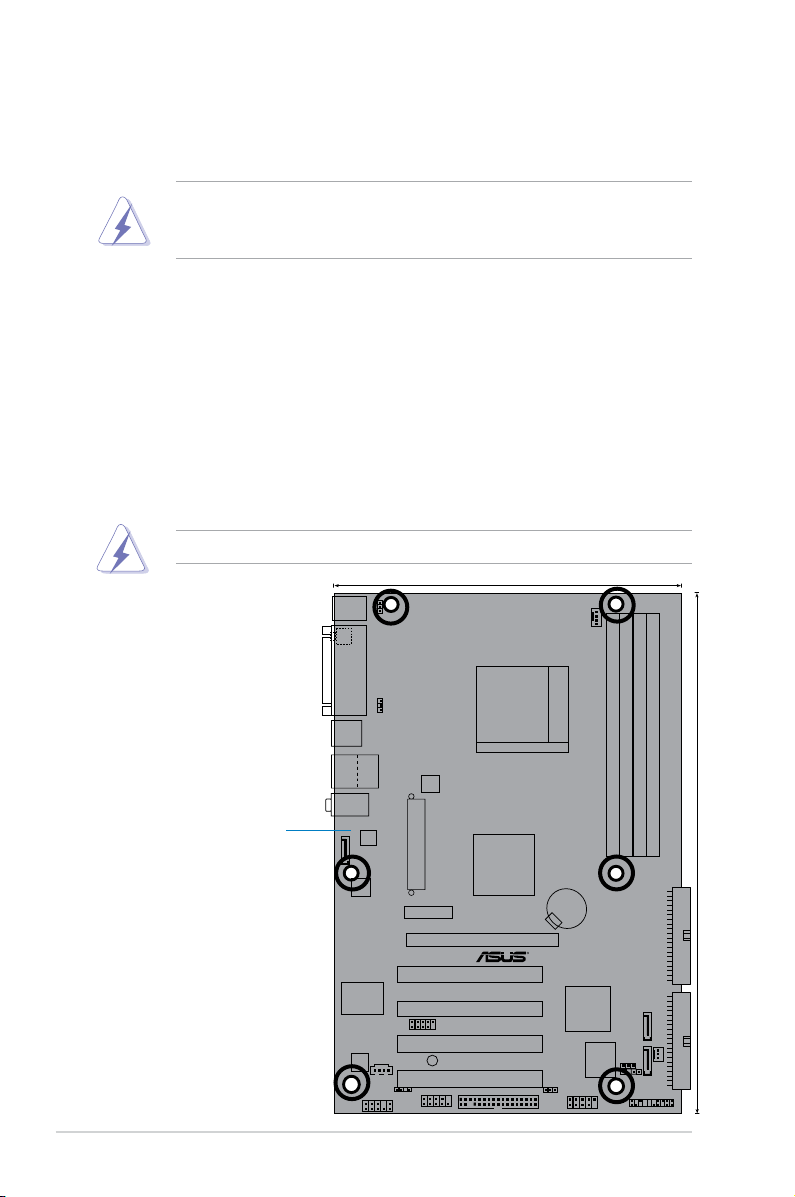
2.2.2 Screw holes
Place nine (6) screws into the holes indicated by circles to secure the
motherboard to the chassis.
Do not overtighten the screws! Doing so can damage the motherboard.
Place this side towards
the rear of the chassis
2-2
Chapter 2: Hardware information

Socket AM2
20.5cm (8.0in)
30.5cm (12.0in)
VIA
K8T890
VT8237A
DDR2 DIMM_B1 (128 bit,240-pin module)
DDR2 DIMM_A1 (128 bit,240-pin module)
DDR2 DIMM_B2(128 bit,240-pin module)
DDR2 DIMM_A2 (128 bit,240-pin module)
PCIEX16_1
PCIEX1_1
PCI1
PCI2
PCI3
PCI4
EATXPWR
ATX12V
AAFP
COM1
CD
FLOPPY
USB56
PANEL
SB_PWR
USBPW2
CLRTC
CHASSIS
SATA2SATA1
CHA_FAN
SPDIF_OUT
CR2032 3V
Lithium Cell
CMOS Power
USB78
SEC_IDE PRI_IDE
CPU_FAN
KBPWR
USBPW1
PS/2KBMS
T: Mouse
B: Keyboard
Below:Mic In
Center:Line Out
Top:Line In
RJ-45
Top:
USB3
USB4
Bottom:
F_USB12
PARALLEL PORT
SPDIF_O1
ALC660
4Mb
BIOS
LAN
SUPER I/O
M 2 V-X
2.2.3 Motherboard layout
ASUS M2V-X
2-3
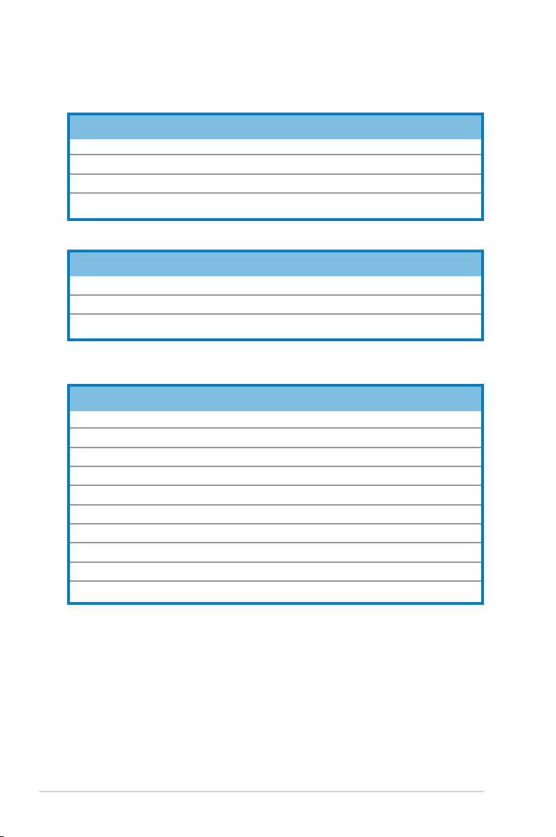
2.2.4 Layout Contents
Slots Page
1. DDR2 DIMM slots 2-11
2. PCI slots 2-17
3. PCI Express x 1 slot 2-17
4. PCI Express x 16 slot 2-17
Jumpers Page
1. Clear RTC RAM (3-pin CLRTC) 2-18
2. Keyboard power (3-pin KBPWR) 2-19
3. USB device wake-up (3-pin USBPWR1, USBPWR2) 2-19
Rear Panel Connectors Page
1. PS/2 mouse port 2-20
2. Parallel port 2-20
3. Gigabit LAN port (RJ-45) 2-20
4. Line In port 2-20
5. Line Out port 2-20
6. Microphone port 2-20
7. USB 2.0 ports 3 and 4 2-21
8. USB 2.0 ports 1 and 2 2-21
9. S/PDIF coaxial cable jack 2-21
10. PS/2 keyboard port 2-21
2-4
Chapter 2: Hardware information

Internal Connectors Page
1. Primary IDE connector (40-1 pin PRI_IDE) 2-22
2. Secondary IDE connector (40-1 pin SEC_IDE) 2-22
3. Floppy disk connector (34-1 pin FLOPPY) 2-23
4. Serial ATA connectors (7-pin SATA1, SATA2) 2-23
5. CPU fan connector (4-pin CPU_FAN) 2-24
6. Chassis fan connector (3-pin CHA_FAN) 2-24
7. CD connector (4-pin CD) 2-25
8. ATX power connector (24-pin ATXPWR) 2-25
9. ATA 12V power connector (4-pin ATX12V) 2-25
10. USB headers (10-1 pin USB56, USB78) 2-26
11. Front panel audio connector (10-1 pin FP_AUDIO) 2-27
12. System panel connector (20-pin PANEL) 2-27
- System power LED (3-pin PLED)
- System warning speaker (4-pin SPEAKER)
- Reset switch (2-pin RESET)
- ATX Power switch (2-pin PWRSW)
- Hard Disk activity LED (2-pin IDE_LED)
ASUS M2V-X
2-5

2.3 Central Processing Unit (CPU)
M2V -X CPU AM2 Socket 940
M2V-X
The motherboard comes with a 940-pin AM2 socket designed for the AMD
Athlon™ 64 X2/Athlon™ 64/Athlon™ FX/Sempron™ processor.
The AM2 socket has a different pinout from the 940-pin socket designed for the
AMD Opteron™ processor. Make sure you use a CPU is designed for the AM2
socket. The CPU ts in only one correct orientation. DO NOT force the CPU into
the socket to prevent bending the connectors on the socket and damaging the
CPU!
2.3.1 Installing the CPU
To install a CPU:
1. Locate the CPU socket on the motherboard.
2. Unlock the socket by pressing the
lever sideways, then lift it up to a
90º- 100º angle.
Make sure that the socket lever is lifted up to 90º-100º angle; otherwise, the
CPU will not t in completely.
2-6
Soc ket l ever
Chapter 2: Hardware information

3. Position the CPU above the socket
such that the CPU corner with the
gold triangle matches the socket
corner with a small triangle.
4. Carefully insert the CPU into the
socket until it ts in place.
Gol d tri angle
Sma ll tr iangl e
5. When the CPU is in place, push
down the socket lever to secure the
CPU. The lever clicks on the side tab
to indicate that it is locked.
6. Install a CPU heatsink and fan
following the instructions that came
with the heatsink package.
ASUS M2V-X
2-7

2.3.2 Installing the heatsink and fan
The AMD Athlon™ 64FX or AMD Athlon 64™ processor require a specially
designed heatsink and fan assembly to ensure optimum thermal condition
and performance.
Make sure that you use only qualied heatsink and fan assembly.
Follow these steps to install the CPU heatsink and fan.
1. Place the heatsink on top of the installed CPU, making sure that the
heatsink ts properly on the retention module base.
• The retention module base is already installed on the motherboard
upon purchase.
• You do not have to remove the retention module base when
installing the CPU or installing other motherboard components.
CPU Fan
Retention Module Base
2-8
CPU Heatsink
Retention bracket lockRetention bracket
Your boxed CPU heatsink and fan assembly should come with
installation instructions for the CPU, heatsink, and the retention
mechanism. If the instructions in this section do not match the CPU
documentation, follow the latter.
Chapter 2: Hardware information
 Loading...