

ASUS M2S-X User Manual

M2S-X
Motherboard
E308 1
Seco n d Edit i o n
Febr u a r y 20 0 7
Copyright © 2007 ASUSTeK COMPUTER INC. All Rights Reserved.
No part of this manual, including the products and software described in it, may be reproduced,
transmitted, transcribed, stored in a retrieval system, or translated into any language in any form
or by any means, except documentation kept by the purchaser for backup purposes, without the
express written permission of ASUSTeK COMPUTER INC. (“ASUS”).
Product warranty or service will not be extended if: (1) the product is repaired, modied or
altered, unless such repair, modication of alteration is authorized in writing by ASUS; or (2)
the serial number of the product is defaced or missing.
ASUS PROVIDES THIS MANUAL “AS IS” WITHOUT WARRANTY OF ANY KIND, EITHER
EXPRESS OR IMPLIED, INCLUDING BUT NOT LIMITED TO THE IMPLIED WARRANTIES
OR CONDITIONS OF MERCHANTABILITY OR FITNESS FOR A PARTICULAR PURPOSE.
IN NO EVENT SHALL ASUS, ITS DIRECTORS, OFFICERS, EMPLOYEES OR AGENTS BE
LIABLE FOR ANY INDIRECT, SPECIAL, INCIDENTAL, OR CONSEQUENTIAL DAMAGES
(INCLUDING DAMAGES FOR LOSS OF PROFITS, LOSS OF BUSINESS, LOSS OF USE
OR DATA, INTERRUPTION OF BUSINESS AND THE LIKE), EVEN IF ASUS HAS BEEN
ADVISED OF THE POSSIBILITY OF SUCH DAMAGES ARISING FROM ANY DEFECT OR
ERROR IN THIS MANUAL OR PRODUCT.
SPECIFICATIONS AND INFORMATION CONTAINED IN THIS MANUAL ARE FURNISHED
FOR INFORMATIONAL USE ONLY, AND ARE SUBJECT TO CHANGE AT ANY TIME
WITHOUT NOTICE, AND SHOULD NOT BE CONSTRUED AS A COMMITMENT BY
ASUS. ASUS ASSUMES NO RESPONSIBILITY OR LIABILITY FOR ANY ERRORS OR
INACCURACIES THAT MAY APPEAR IN THIS MANUAL, INCLUDING THE PRODUCTS
AND SOFTWARE DESCRIBED IN IT.
Products and corporate names appearing in this manual may or may not be registered
trademarks or copyrights of their respective companies, and are used only for identication or
explanation and to the owners’ benet, without intent to infringe.
ii

Contents
Notices ................................................................................................ vi
Safety information ..............................................................................vii
About this guide .................................................................................viii
Typography ......................................................................................... ix
M2S-X specications summary ............................................................. x
Chapter 1: Product introduction
1.1 Welcome! .............................................................................. 1-2
1.2 Package contents .................................................................
1.3 Special features ....................................................................
1.3.1 Product highlights ...................................................
1.3.2 Unique ASUS features .............................................
1.4 Before you proceed ..............................................................
1.5 Motherboard overview ..........................................................
1.5.1 Motherboard layout ................................................
1.5.2 Placement direction ................................................
1.5.3 Screw holes .............................................................
1.6 Central Processing Unit (CPU) ..............................................
1.6.1 Overview .................................................................
1.6.2 Installling the CPU ...................................................
1.6.3 Installing the heatsink and fan ..............................
1.7 System memory ..................................................................
1.7.1 DIMM sockets location ..........................................
1.7.2 Memory congurations .........................................
1.7.3 Installing a DIMM ...................................................
1.8 Expansion slots ...................................................................
1.8.1 Standard interrupt assignments ...........................
1.8.2 IRQ assignments for this motherboard .................
1.8.3 PCI slots ................................................................
1.8.4 PCI Express x1 slot ..............................................
1.8.5 PCI Express x16 slot ............................................
1.9 Jumpers ..............................................................................
1.10 Connectors .........................................................................
1.10.1 Rear panel connectors ..........................................
1.10.2 Internal connectors ...............................................
1-2
1-3
1-3
1-4
1-5
1-6
1-6
1-7
1-7
1-8
1-8
1-8
1-10
1-12
1-12
1-12
1-16
1-16
1-17
1-17
1-18
1-18
1-18
1-19
1-21
1-21
1-23
iii
Contents
Chapter 2: BIOS setup
2.1 Managing and updating your BIOS ........................................ 2-2
2.1.1 Creating a bootable oppy disk ..............................
2.1.2 Using AFUDOS to update the BIOS .........................
2.1.3 Using AFUDOS to copy BIOS from PC .....................
2.1.4 Using ASUS EZ Flash 2 to update the BIOS .............
2.1.5 Recovering the BIOS with CrashFree BIOS 3 ...........
2.2 BIOS Setup program .............................................................
2.2.1 BIOS menu screen .................................................
2.2.2 Menu bar ...............................................................
2.2.3 Navigation keys .....................................................
2.2.4 Menu items ...........................................................
2.2.5 Sub-menu items ....................................................
2.2.6 Conguration elds ...............................................
2.2.7 Pop-up window ......................................................
2.2.8 Scroll bar ...............................................................
2.2.9 General help ..........................................................
2.3 Main menu ...........................................................................
2.3.1 System Time .........................................................
2.3.2 System Date .........................................................
2.3.3 Legacy Diskette A ...............................................
2.3.4 Primary and Secondary IDE Master/Slave .............
2.3.5 SATA1 and SATA2 ................................................
2.3.6 IDE Conguration ..................................................
2.3.7 System Information
2.4 Advanced menu ..................................................................
2.4.1 USB Conguration .................................................
2.4.2 JumperFree Conguration .....................................
2.4.3 CPU Conguration .................................................
2.4.4 Chipset ..................................................................
2.4.5 Onboard Devices Conguration .............................
2.4.6 PCI PnP ..................................................................
............................................... 2-17
2-2
2-3
2-4
2-5
2-6
2-9
2-10
2-10
2-10
2-11
2-11
2-11
2-11
2-11
2-11
2-12
2-12
2-12
2-12
2-13
2-14
2-16
2-17
2-18
2-19
2-20
2-20
2-26
2-27
iv
Contents
2.5 Power menu ........................................................................ 2-28
2.5.1 Suspend Mode .......................................................
2.5.2 ACPI Version Features ..........................................
2.5.3 ACPI APIC Support ...............................................
2.5.4 APM Conguration ...............................................
2.5.5 Hardware Monitor
2.6 Boot menu ..........................................................................
2.6.1 Boot Device Priority ..............................................
2.6.2 Boot Settings Conguration .................................
2.6.3 Security .................................................................
2.7 Tools menu .........................................................................
2.7.1 ASUS EZ Flash 2 ....................................................
2.8 Exit menu ............................................................................
Chapter 3: Software support
3.1 Installing an operating system .............................................. 3-2
3.2 Support CD information ........................................................
3.2.1 Running the support CD ..........................................
3.2.2 Drivers menu ...........................................................
3.2.3 Utilities menu ..........................................................
3.2.4 Make Disk ................................................................
3.2.5 Manual ....................................................................
3.2.6 ASUS Contact information ......................................
................................................. 2-30
2-28
2-28
2-28
2-29
2-31
2-32
2-32
2-33
2-35
2-35
2-36
3-2
3-2
3-3
3-3
3-5
3-5
3-6
v
Notices
Fed er al Co mm un ica ti on s C om mi ssi on S tat em en t
This device complies with Part 15 of the FCC Rules. Operation is subject to
the following two conditions:
•
This device may not cause harmful interference, and
•
This device must accept any interference received including
interference that may cause undesired operation.
This equipment has been tested and found to comply with the limits for a
Class B digital device, pursuant to Part 15 of the FCC Rules. These limits
are designed to provide reasonable protection against harmful interference
in a residential installation. This equipment generates, uses and can radiate
radio frequency energy and, if not installed and used in accordance with
manufacturer’s instructions, may cause harmful interference to radio
communications. However, there is no guarantee that interference will
not occur in a particular installation. If this equipment does cause harmful
interference to radio or television reception, which can be determined by
turning the equipment off and on, the user is encouraged to try to correct
the interference by one or more of the following measures:
•
Reorient or relocate the receiving antenna.
•
Increase the separation between the equipment and receiver.
•
Connect the equipment to an outlet on a circuit different from that to
which the receiver is connected.
•
Consult the dealer or an experienced radio/TV technician for help.
The use of shielded cables for connection of the monitor to the graphics
card is required to assure compliance with FCC regulations. Changes
or modications to this unit not expressly approved by the party
responsible for compliance could void the user’s authority to operate
this equipment.
Can ad ia n D ep ar tme nt o f C om mu nic at io ns St at eme nt
This digital apparatus does not exceed the Class B limits for radio noise
emissions from digital apparatus set out in the Radio Interference
Regulations of the Canadian Department of Communications.
This class B digital apparatus complies with Canadian
ICES-003.
vi

Safety information
Ele ct ri cal s af ety
•
To prevent electrical shock hazard, disconnect the power cable from
the electrical outlet before relocating the system.
•
When adding or removing devices to or from the system, ensure that
the power cables for the devices are unplugged before the signal
cables are connected. If possible, disconnect all power cables from the
existing system before you add a device.
•
Before connecting or removing signal cables from the motherboard,
ensure that all power cables are unplugged.
•
Seek professional assistance before using an adapter or extension
cord. These devices could interrupt the grounding circuit.
•
Make sure that your power supply is set to the correct voltage in your
area. If you are not sure about the voltage of the electrical outlet you
are using, contact your local power company.
•
If the power supply is broken, do not try to fix it by yourself. Contact
a qualified service technician or your retailer.
Ope ra ti on sa fe ty
•
Before installing the motherboard and adding devices on it, carefully
read all the manuals that came with the package.
•
Before using the product, make sure all cables are correctly connected
and the power cables are not damaged. If you detect any damage,
contact your dealer immediately.
•
To avoid short circuits, keep paper clips, screws, and staples away from
connectors, slots, sockets and circuitry.
•
Avoid dust, humidity, and temperature extremes. Do not place the
product in any area where it may become wet.
•
Place the product on a stable surface.
•
If you encounter technical problems with the product, contact a
qualified service technician or your retailer.
The symbol of the crossed out wheeled bin indicates that the product
(electrical and electronic equipment) should not be placed in municipal
waste. Check local regulations for disposal of electronic products.
vii
About this guide
This user guide contains the information you need when installing and
conguring the motherboard.
How t hi s g ui de is o rg ani ze d
This manual contains the following parts:
• Chap t e r 1: P r o duct i n trod u c t ion
This chapter describes the features of the motherboard and the
new technology it supports. This chapter also lists the hardware
setup procedures that you have to perform when installing system
components. It includes description of the jumpers and connectors on
the motherboard.
• Chap t e r 2: B I O S se t u p
This chapter tells how to change system settings through the BIOS
Setup menus. Detailed descriptions of the BIOS parameters are also
provided.
• Chap t e r 3: S o f twar e s uppo r t
This chapter describes the contents of the support CD that comes
with the motherboard package.
.
Whe re t o f in d mor e in for ma ti on
Refer to the following sources for additional information and for product
and software updates.
1. ASUS w e bsit e s
The ASUS website provides updated information on ASUS hardware
and software products. Refer to the ASUS contact information.
2. Opti o n a l do c u m enta t i o n
Your product package may include optional documentation, such as
warranty yers, that may have been added by your dealer. These
documents are not part of the standard package.
viii
Con ve nt ion s us ed in t his g ui de
To make sure that you perform certain tasks properly, take note of the
following symbols used throughout this manual.
DANGER/WARNING: Information to prevent injury to yourself
when trying to complete a task.
CAUTION: Information to prevent damage to the components
when trying to complete a task.
I
MPORTANT: Instructions that you MUST follow to complete a
task.
NOTE: Tips and additional information to help you complete a
task.
Typography
Bold text Indicates a menu or an item to select
Italics
Used to emphasize a word or a phrase
<Key> Keys enclosed in the less-than and greater-than sign means
that you must press the enclosed key
Example: <Enter> means that you must press the Enter or
Return key
<Key1>+<Key2>+<Key3> If you must press two or more keys simultaneously, the
key names are linked with a plus sign (+)
Example: <Ctrl>+<Alt>+<D>
Command Means that you must type the command exactly as shown,
then supply the required item or value enclosed in
brackets
Example: At the DOS prompt, type the command line:
afudos /i[lename]
afudos /iM2S-X.ROM
ix
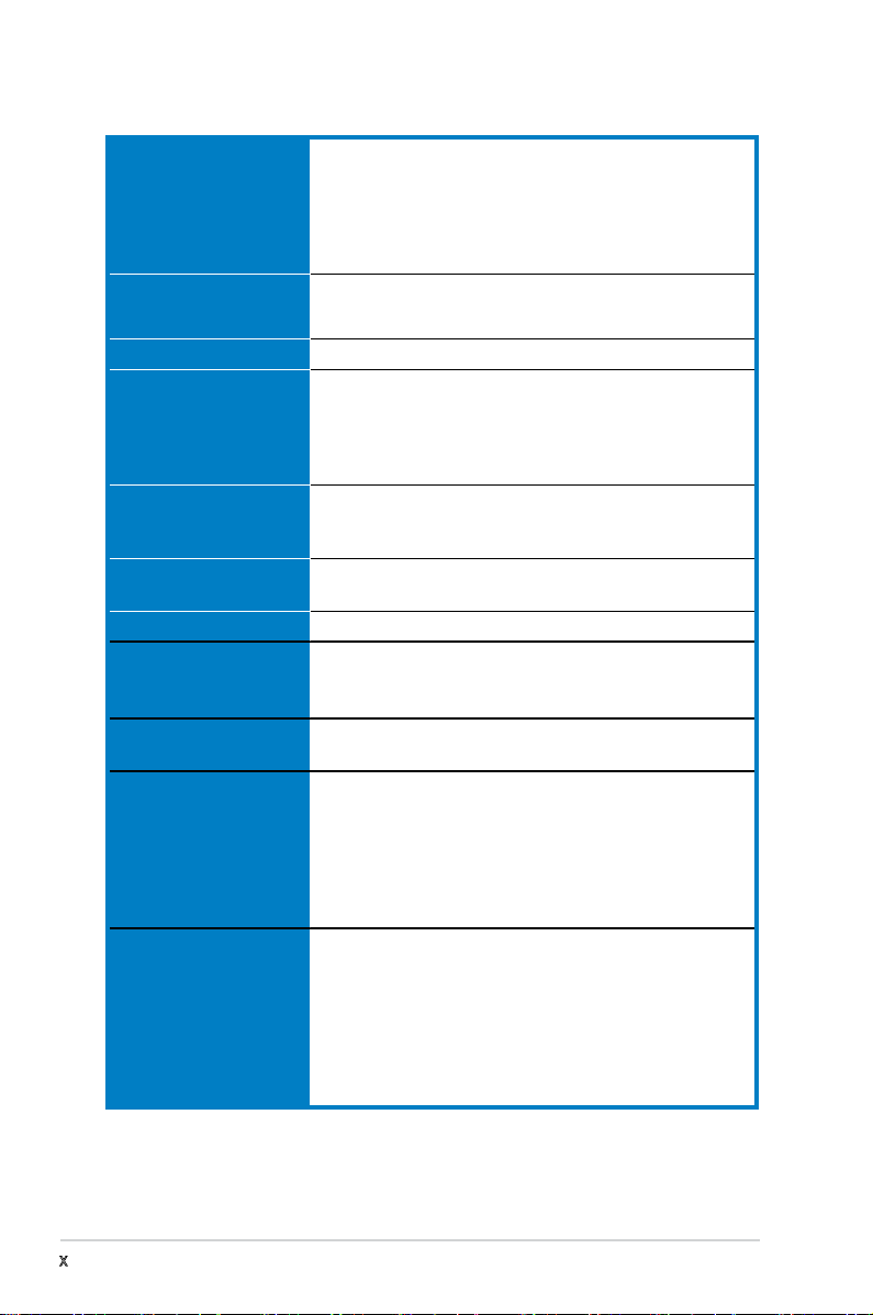
M2S-X specications summary
CPU Socket AM2 for AMD Athlon™ 64 FX/AMD Athlon™ 64 X2
Chipset SIS® 756
System bus 2000 / 1600 MT/s
Memory Dual-channel memory architecture
Expansion slots 1 x PCI Express™ x16 slot
Storage 2 x Ultra DMA 133/100/66/33
LAN Realtek® RTL8201CL 10/100 LAN
Audio C-Media Superior Quality Audio 7.1 channel audio
USB Supports up to 6 USB 2.0 ports (two at mid-board, four on
ASUS special features ASUS C.P.R.
Rear panel 1 x Parallel port
/AMD Athlon 64™/AMD Sempron™ processors
Supports AMD Cool ‘n’ Quiet™ Technology
AMD64 architecture enables simultaneous 32-bit and
64-bit computing
AMD Live!™ ready
SIS® 965L
- 4 x 240-pin DIMM sockets support unbuffered
ECC/non-ECC DDR2 800/667/533 MHz memory
modules
- Supports up to 4 GB system memory
2 x PCI Express™ x1 slots
3 x PCI 2.2 slots
2 x SATA support RAID 0, 1, and JBOD
CODEC
Supports S/PDIF Out interface
the rear panel)
ASUS MyLogo
ASUS CrashFree BIOS 3
ASUS EZ Flash 2
ASUS Q-Fan
SFS (Stepless Frequency Selection) from 200MHz up to
400MHz at 1MHz increment
1 x PS/2 keyboard port (purple)
1 x PS/2 mouse port (green)
1 x Serial port
1 x S/PDIF Out port (Coaxial)
1 x LAN (RJ-45) ports
4 x USB 2.0/1.1 ports
8-channel audio I/O ports
(continued on the next page)
x
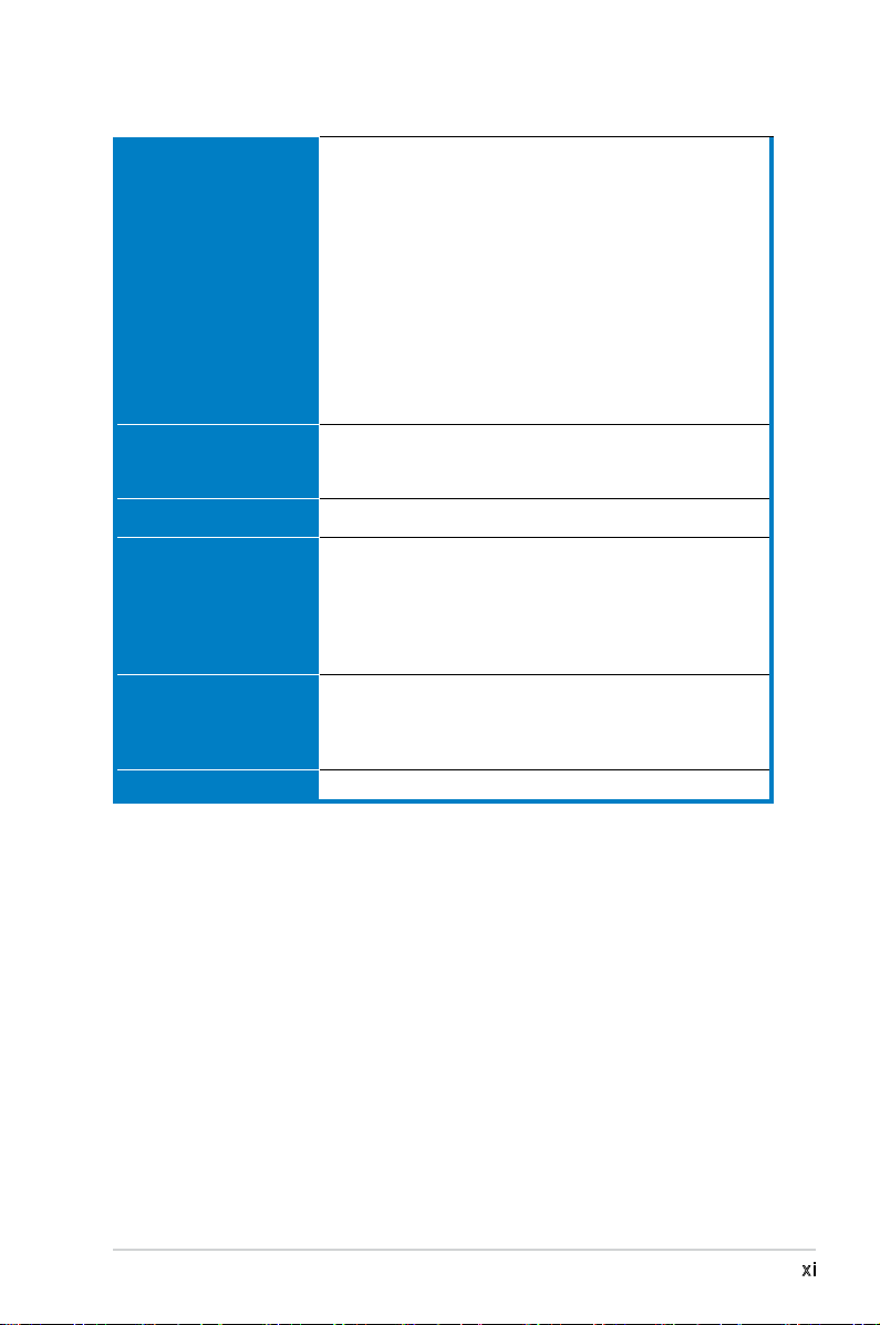
M2S-X specications summary
Internal connectors 1 x USB 2.0 connector supports additional 2 USB 2.0
BIOS features 4 Mb Flash ROM, AMI BIOS, PnP, DMI 2.0, WfM2.0, SM
Manageability WfM 2.0, DMI 2.0, WOL by PME, WOR by PME, PXE
Accessories UltraDMA cable
Support CD contents Drivers
Form factor ATX form factor: 12 in x 8.6 in (30.5 cm x 21.8 cm)
ports
1 x Floppy disk drive connector
2 x IDE connector
2 x Serial ATA connectors
1 x CPU fan / 1 x Chassis fan 1
1 x Chassis intrusion connector
1 x S/PDIF out header connector
Front panel audio connector
CD audio in connectors
24-pin ATX power connector
4-pin ATX 12 V power connector
System panel connector
BIOS 2.3, ACPI 2.0a, ASUS EZ Flash 2, ASUS CrashFree
BIOS 3
FDD cable
SATA cable
SATA power cable
I/O Shield
User’s maual
ASUS PC Probe II
ASUS Update
Anti-virus software (OEM version)
*Specications are subject to change without notice.
xi

xii

This chapter describes the motherboard
features and the new technologies
it supports.
introduction
Product
1
1.1 Welcome!
T h a n k y o u f o r b u y i n g a n A SU S® M 2 S - X m o t h e r b o a r d !
The motherboard delivers a host of new features and latest technologies,
making it another standout in the long line of ASUS quality motherboards!
Before you start installing the motherboard, and hardware devices on it,
check the items in your package with the list below.
1.2 Package contents
Check your motherboard package for the following items.
Motherboard ASUS M2S-X motherboard
Cables 1 x Ultra DMA cable
1 x SATA power cable
1 x SATA signal cable
1 x Floppy disk cable
Accessories I/O shield
Application CDs ASUS motherboard support CD
Documentation User guide
If any of the above items is damaged or missing, contact your retailer.
1-2
Chapter 1: Product introduction

1.3 Special features
1.3 .1 Pro du ct Hi gh li ght s
Lat e st pro c es s or t ec h nol o gy
The motherboard comes with a 940-pin AM2 socket that supports AMD
Athlon™ 64 FX/AMD Athlon™ 64 X2/AMD Athlon™ 64/AMD Sempron™
processors. With an integrated low-latency high-bandwidth memory
controller and a highly scalable HyperTransport™ technology-based system
bus, the motherboard provides a powerful platform for your diverse
computing needs, increased ofce productivity, and enhanced digital media
experience.
Hyp e rT r ans p or t ™ T e ch n olo g y
HyperTransport™ Technology is a high-speed, low latency, point-to-point
link designed to increase the communication speed between integrated
circuits in computers, networking and telecommunicatons equipment up to
48 times faster than other existing technologies.
Coo l ‘ n ’ Q u ie t !™ T ec h nol o gy
The motherboard supports the AMD® Cool ‘n’ Quiet!™ Technology that
dynamically and automatically changes the CPU speed, voltage and amount
of power depending on the task the CPU performs.
Ser i al ATA RA I D s o lu t ion
The motherboard provides a high-performance Serial ATA RAID controller
that enhance hard disk performance and data backup protection without
the cost of additional RAID cards. The onboard SIS 965L RAID controller
provides two Serial ATA connectors for RAID 0, RAID 1 and JBOD functions.
S/P D IF out
The motherboard’s S/PDIF out function turns your computer into a high-
end entertainment system with digital connectivity to powerful speaker
systems.
PCI Ex p res s ™ i nte r fa c e
The motherboard fully supports PCI Express, the latest I/O interconnect
technology that speeds up the PCI bus. PCI Express features point-to-point
serial interconnections between devices and allows higher clockspeeds by
carrying data in packets. This high speed interface is software compatible
with existing PCI specications.
ASUS M2S-X
1-3
1.3 .2 Uni qu e ASU S fe atu re s
Cra s hF r ee B IO S 3
The ASUS CrashFree BIOS 3 allows users to restore corrupted BIOS data
from a USB ash disk containing the BIOS le. This utility saves users the
cost and hassle of buying a replacement BIOS chip.
C.P . R. (CP U P a ram e te r Re c al l )
The C.P.R. feature of the motherboard BIOS allows automatic re-setting to
the BIOS default settings in case the system hangs due to overclocking.
When the system hangs due to overclocking, C.P.R. eliminates the need
to open the system chassis and clear the RTC data. Simply shut down
and reboot the system, and BIOS automatically restores the CPU previous
setting for each parameter.
ASU S M y Log o ™
This new feature present in the motherboard allows you to personalize and
add style to your system with customizable boot logos.
ASU S E Z Fl a sh 2
EZ Flash 2 is a user-friendly BIOS update utility. Simply press the predened
hotkey to launch the utility and update the BIOS without entering the OS.
Update your BIOS easily without preparing a bootable diskette or using an
OS-based ash utility.
ASU S Q - Fan te c hno l og y
The ASUS Q-Fan technology smartly adjusts the fan speeds according to
the system loading to ensure quiet, cool, and efcient operation.
1-4
Chapter 1: Product introduction
M2S-X
R
M2S-X
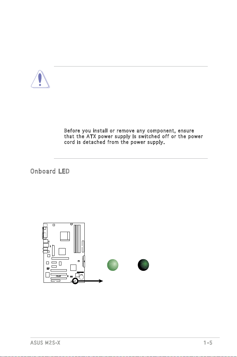
Onboard LED
SB_PWR
ON
Standby
Power
OFF
Powered
Off
1.4 Before you proceed
Take note of the following precautions before you install motherboard
components or change any motherboard settings.
• Unplug the power cord from the wall socket before touching any
component.
• Use a grounded wrist strap or touch a safely grounded object or
to a metal object, such as the power supply case, before handling
components to avoid damaging them due to static electricity
• Hold components by the edges to avoid touching the ICs on them.
• Whenever you uninstall any component, place it on a grounded
antistatic pad or in the bag that came with the component.
Before you install or remove any component, ensure
•
that the ATX power supply is switched off or the power
cord is detached from the power supply. Failure to do so
may cause severe damage to the motherboard, peripherals, and/or
components.
Onb o ar d LE D
The motherboard comes with a green standby power LED that lights
up to indicate that the system is ON, in sleep mode, or in soft-off
mode. This is a reminder that you should shut down the system
and unplug the power cable before removing or plugging in any
motherboard component.
ASUS M2S-X
1-5

21.8cm(8.6in)
30.5cm(12.0in)
Socket AM2
DDR2 DIMM_A1 (64 bit,240-pin module)
DDR2 DIMM_B1 (64 bit,240-pin module)
DDR2 DIMM_A2 (64 bit,240-pin module)
DDR2 DIMM_B2 (64 bit,240-pin module)
M2S-X
SEC_IDE
PRI_IDE
EATXPWR
SIS 756
SIS 965L
CR2032 3V
Lithium Cell
CMOS Power
4Mb
BIOS
SATA2
SATA1
CHA_FAN
CPU_FAN
PANEL
SB_PWR
CHASSIS
CLRTC
Super I/O
FLOPPY
PCI2
PCI1
PCI3
PCIEX16
PCIEX1_1
PCIEX1_2
R
USB56
FP_AUDIO
USBPW56
SPDIF_OUT
ICS953805CFLF
CM6501
RTL8201CL
USBPW34
USBPW12
CD
ATX12V
AUDIO2
AUDIO1
LAN_USB34
USB12
SPDIF_O1
PARALLE PORT
COM1
PS/2KBMS
T: Mouse
B: Keyboard
1.5 Motherboard overview
1.5 .1 Mot he rb oar d la you t
1-6
Chapter 1: Product introduction
M2S-X
R
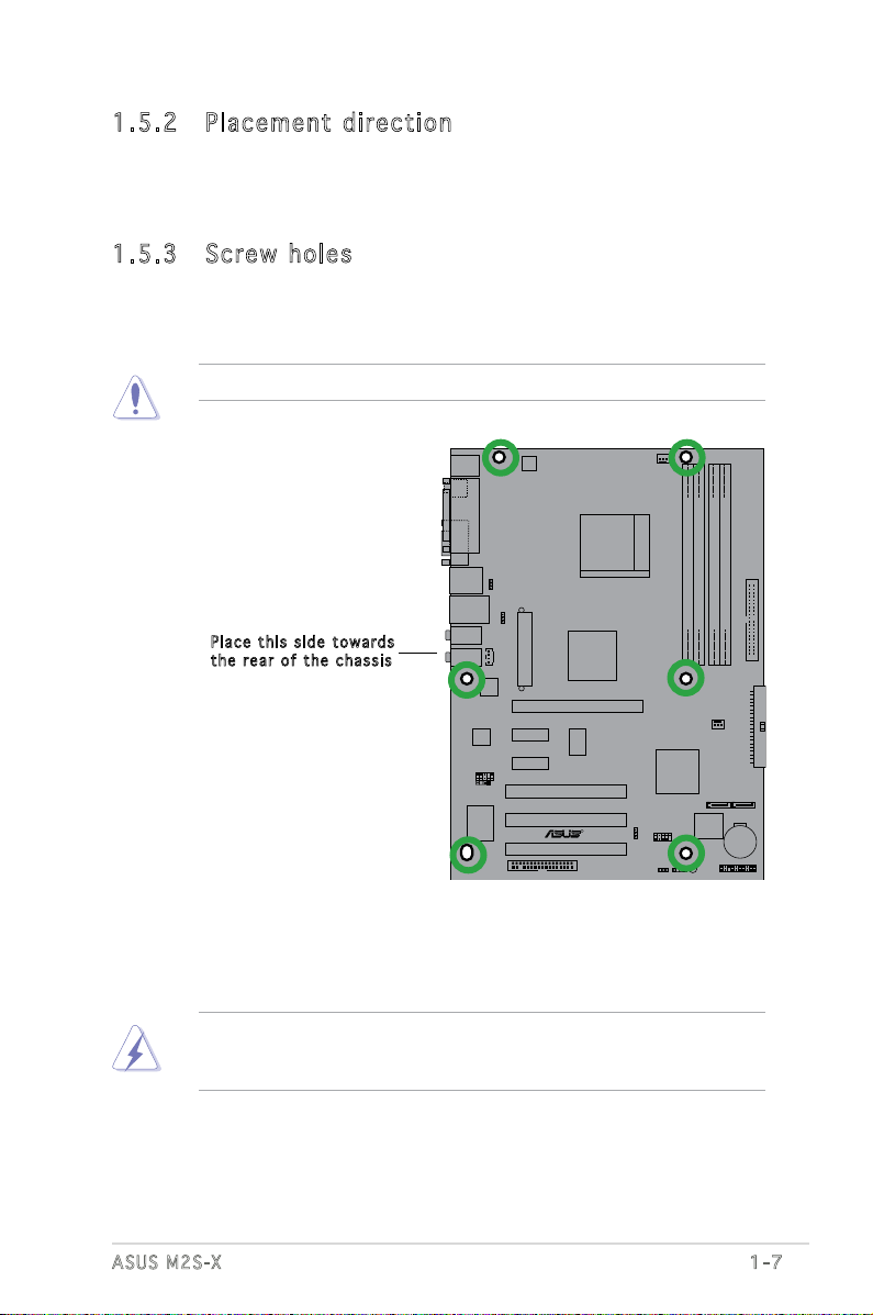
1.5 .2 Pla ce me nt di re cti on
When installing the motherboard, make sure that you place it into the
chassis in the correct orientation. The edge with external ports goes to the
rear part of the chassis as indicated in the image below.
1.5 .3 Scr ew h ole s
Place six (6) screws into the holes indicated by circles to secure the
motherboard to the chassis.
Do not overtighten the screws! Doing so may damage the motherboard.
Pla c e this s i d e tow a r d s
the r e ar of t h e cha s s i s
Before you install the motherboard, study the conguration of your chassis
to ensure that the motherboard ts into it.
Make sure to unplug the power cord before installing or removing the
motherboard. Failure to do so can cause you physical injury and damage
motherboard components.
ASUS M2S-X
1-7

1.6 Central Processing Unit (CPU)
M2S-X
R
M2S-X
CPU Socket M2
1.6 .1 Ove rv ie w
The motherboard comes with a surface mount 940-pin AM2 socket
designed for the AMD Athlon™ 64, AMD Athlon™ 64 X2, AMD Athlon™ 64
FX, and AMD Sempron™ Processors.
Take note of the marked corner (with
gold triangle) on the CPU. This mark
should match a specic corner on the
socket to ensure correct installation.
Gold triangle
1.6 .2 Ins ta ll lin g th e C PU
To install a CPU:
1. Locate the CPU socket on the motherboard.
1-8
Before installing the CPU, make sure that the socket box is facing
towards you and the load lever is on your left.
Incorrect installation of the CPU into the socket may bend the pins and
severely damage the CPU!
Chapter 1: Product introduction
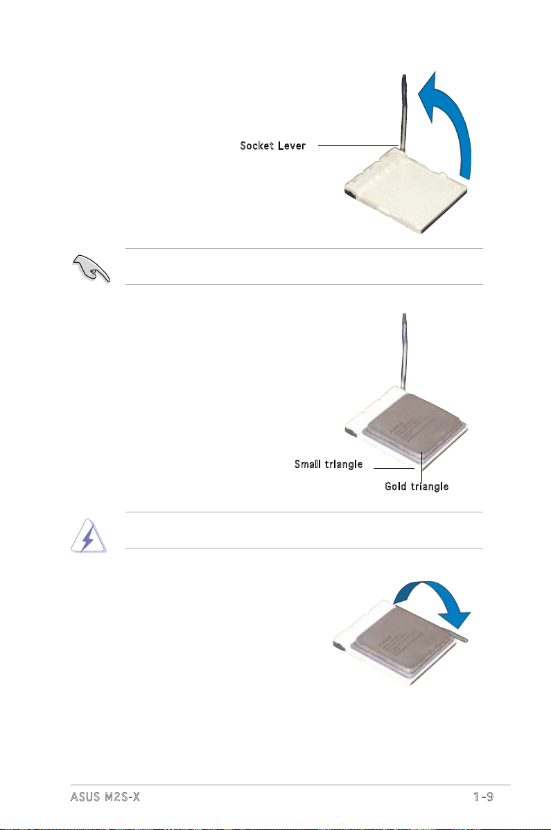
2. Unlock the socket by pressing the
lever sideways, then lift it up to a
90°-100° angle.
Soc k e t Leve r
Make sure that the socket lever is lifted up to 90°-100° angle, otherwise
the CPU does not t in completely.
3. Position the CPU above the
socket such that the CPU corner
with the gold triangle matches
the socket corner with a small
triangle.
4. Carefully insert the CPU into the
socket until it ts in place.
Sma l l trian g l e
Gol d t riang l e
The CPU ts only in one correct orientation. DO NOT force the CPU into
the socket to prevent bending the pins and damaging the CPU!
5. When the CPU is in place, push
down the socket lever to secure
the CPU. The lever clicks on the
side tab to indicate that it is
locked.
6. Install specically designed
heatsink and fan assembly.
ASUS M2S-X
1-9
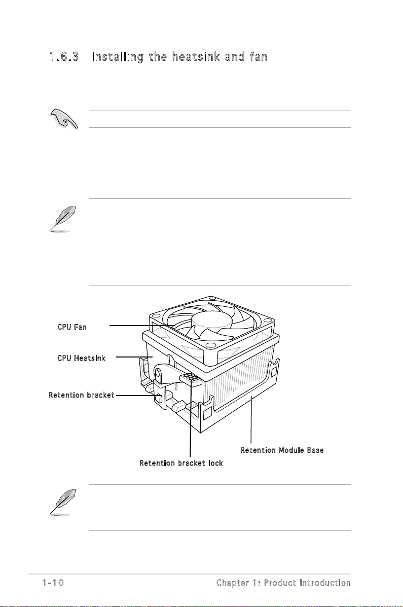
1.6 .3 Ins ta ll ing t he h e at si nk an d fa n
The AMD Athlon™ 64, AMD Athlon™ 64 X2, AMD Athlon™ 64 FX, or
AMD Sempron™ processors require a specially designed heatsink and fan
assembly to ensure optimum thermal condition and performance.
Make sure that you use only qualied heatsink and fan assembly.
Follow these steps to install the CPU heatsink and fan.
1. Place the heatsink on top of the installed CPU, making sure that the
heatsink ts properly on the retention module base.
• The retention module base is already installed on the motherboard
upon purchase.
• You do not have to remove the retention module base when
installing the CPU or installing other motherboard components.
• If you purchased a separate CPU heatsink and fan assembly, make
sure that a Thermal Interface Material is properly applied to the CPU
heatsink or CPU before you install the heatsink and fan assembly.
CPU F a n
CPU H e atsin k
Ret e n t ion b r a c ket
Your boxed CPU heatsink and fan assembly should come with installation
instructions for the CPU, heatsink, and the retention mechanism. If the
instructions in this section do not match the CPU documentation, follow
the latter.
1-10
Ret e n t ion M o d u le Ba s e
Ret e n t ion b r a c ket l o c k
Chapter 1: Product introduction
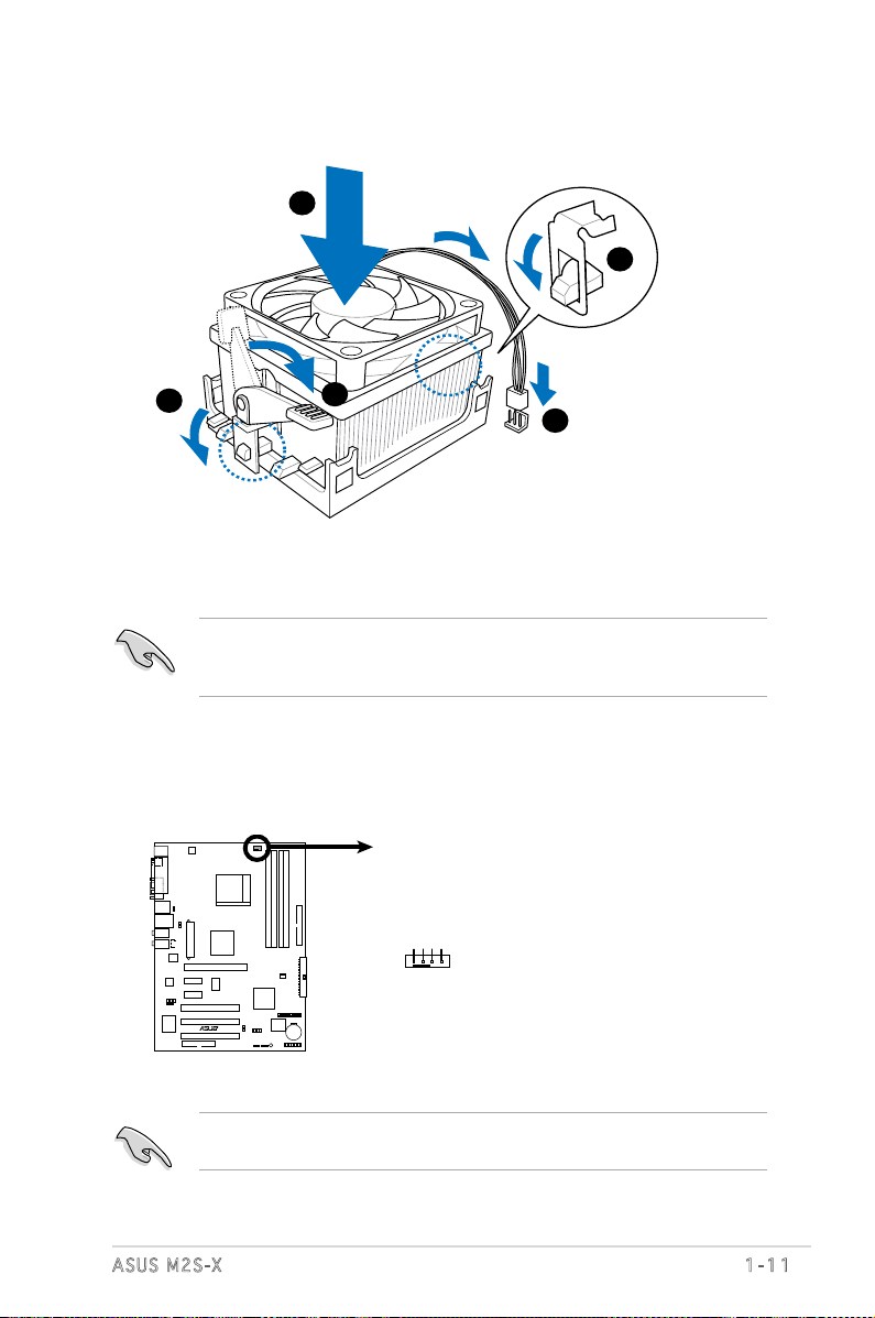
2. Attach one end of the retention bracket to the retention module base.
1
3
4
5
2
M2S-X
R
M2S-X
CPU Fan Connector
CPU_FAN
GND
CPU FAN PWR
CPU FAN IN
CPU FAN PWM
3. Align the other end of the retention bracket (near the retention
bracket lock) to the retention module base. A clicking sound denotes
that the retention bracket is in place.
Make sure that the fan and heatsink assembly perfectly ts the retention
mechanism module base, otherwise you cannot snap the retention
bracket in place.
4. Push down the retention bracket lock on the retention mechanism to
secure the heatsink and fan to the module base.
5. When the fan and heatsink assembly is in place, connect the CPU fan
cable to the connector on the motherboard labeled CPU_FAN.
ASUS M2S-X
Do not forget to connect the CPU fan connector! Hardware monitoring
errors can occur if you fail to plug this connector.
1-11

1.7 System memory
M2S-X
R
M2S-X
240-pin DDR2 DIMM Sockets
112 Pins
128 Pins
DIMM_A1
DIMM_A2
DIMM_B1
DIMM_B2
1.7 .1 DIM M so cke ts l oca ti on
The following gure illustrates the location of the DDR2 DIMM sockets.
• Make sure to unplug the power supply before adding or removing DIMMs or
other system components. Failure to do so may cause severe damage to
both the motherboard and the components.
• We recommend to install the memory modules rst before installing a PCI
Express x16 card.
1.7 .2 Mem or y con fi gu rat io ns
You may install 256MB, 512MB, 1GB, and 2GB unbuffered ECC/non-ECC
DDR2 DIMMs into the DIMM sockets.
Rec om me nde d Me mor y Co nfi gu ra tio ns
Single Channel
Dual-channel (1)
Dual-channel (2)
1-12
Mode
Sockets
DIMM_A1 DIMM_B1 DIMM_A2 DIMM_B2
Populated - - -
- - Populated -
- Populated - -
- - - Populated
Populated Populated - -
- - Populated Populated
Populated Populated Populated Populated
Chapter 1: Product introduction
* For dual-channel memory conguration (2), you may:
• install identical DIMMs in all four sockets OR
• install an identical DIMM pair in DIMM_A1 and DIMM_B1 (yellow
sockets) and another identical DIMM pair in DIMM_A2 and
DIMM_B2 (black sockets)
* Always use identical DDR2 DIMM pairs for dual-channel model. For
optimum compatibility, we recommend that you obtain memory
modules from the same vendor. Visit the ASUS website (www.asus.
com) for the latest Qualied Vendors List.
Important notice on installing Windows® XP 32-bit version
If you install Windows® XP 32-bit version Operating System (OS), the
limitation of this OS version is that it may reserve a certain amount of
memory space for system devices. We recommend that you install less
than 3 GB system memory if you would like to work under Windows
®
XP
32-bit version OS. The excess memory installation will not cause any
usage problem, but it will not give users the benet of manipulating this
excess memory space.
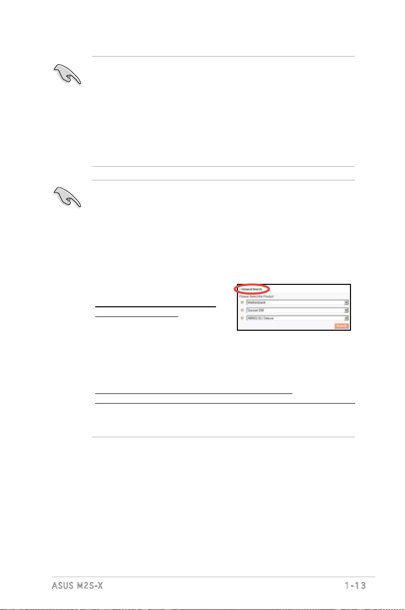
Visit the ASUS FAQ site for further
explanation:
http://support.asus.com/faq/faq.
aspx?SLanguage=en-us
Under General Search, make the
selections as shown, then click
Search. Click the article titled “4GB
memory installed but less memory size detected.”
ASUS M2S-X
You also may check the URLs below for third party comments on this
issue:
http://dlsvr01.asus.com/pub/ASUS/mb/4GB_Rev1.pdf
http://www.intel.com/support/motherboards/server/sb/cs-016594.htm
Due to chipset limitation, this motherboard can only support up to
3 GB on the 64-bit operating systems.
1-13
DDR 2 80 0 Q u ali f ie d Ve n do r s L i st
DIMM s u p port
Siz e Ve n d o r Mode l S S/DS Comp o n e n t A B C
512MB Kingston KVR800D2N5/512 SS K4T51083QC-ZCE7 v v v
512MB Kingston KVR800D2N5/512 SS V59C1512804QBF25S0054707PEBPA v v v
1G Kingston KVR800D2N5/1G DS K4T51083QC-ZCE7 v v v
1G Kingston KHX6400D2LL/1G DS Heat-Sink Package v v v
1G Kingston KVR800D2N5/1G DS NT5TU64M8BE-25C62321800CP v v v
512MB Samsung KR M378T6553CZ3-CE7 SS K4T51083QC-ZCE7 v v v
1G Samsung KR M378T2953CZ3-CE7 DS K4T51083QC-ZCE7 v v v
512MB Samsung KR M391T6553CZ3-CE7 SS K4T51083QC-ZCE7(ECC) v v v
1G Samsung KR M391T2953CZ3-CE7 DS K4T51083QC-ZCE7(ECC) v v v
256MB Qimonda HYS64T32001HU-2.5-A SS HYB18T256800AF25SSS49313 v v v
512MB Qimonda HYS64T64020HU-2.5-A DS HYB18T256800AF25SSS25063 v v v
512MB Micron MT9HTF6472AY-80ED4 SS 6ED22D9GKX(ECC) v v v
512MB Corsair CM2X512A-6400 SS Heat-Sink Package v v v
1G Corsair CM2X1024-6400 DS Heat-Sink Package v v v
512MB HY HYMP564U64AP8-S6 AA SS HY5PS12821AFP-S6 v v v
512MB HY HYMP564U64BP8-S5 AB SS HY5PS12821BFP-S5 v v v
1G HY HYMP512U64AP8-S6 AA DS HY5PS12821AFP-S6 v v v
1G HY HYMP512U64BP8-S5 AB DS HY5PS12821BFP-S5 v v v
512MB VDATA M2GVD6G3H3160I1E53 SS VD29608A8A-25EG30648 v v v
1G VDATA M2GVD6G3I4170I1E53 DS VD29608A8A-25EG30647 v v v
DDR 2 66 7 Q u ali f ie d Ve n do r s L i st
DIMM s u p port
Siz e Ve n d o r Mode l SS/DS Compo n e n t A B C
256MB Kingston KVR667D2N5/256 SS E2508AB-6E-E v v v
512MB Kingston KVR667D2N5/512 SS D6408TE8WL-27 v v v
512MB Kingston KVR667D2E5/512 SS E5108AE-6E-E(ECC) v v v
1G Kingston KVR667D2N5/1G DS D6408TE8WL-3 v v v
512MB Samsung KR M378T6553CZ0-CE6 SS K4T51083QC v v v
512MB Samsung KR M378T6453FZ0-CE6 DS K4T56083QF-ZCE6 v v v
512MB Samsung M378T6553CZ3-CE6 SS K4T51083QC-ZCE6 v v v
1G Samsung M378T2953CZ3-CE6 DS K4T51083QC-ZCE6 v v v
1G Samsung KR M378T2953CZ0-CE6 DS K4T51083QC-ZCE6 v v v
256MB Qimonda HYS64T32000HU-3S-A SS HYB18T512160AF-3SSSS17310 v v v
512MB Qimonda HYS64T32000HU-3S-A SS HYB18T5128000AF-3SSSS27416 v v v
512MB Qimonda HYS64T64000HU-3S-A SS HYB18T512800AF3SFSS05346 v v v
1G Qimonda HYS64T128020HU-3S-A DS HYB18T512800AF3SSSS28104 v v v
512MB Corsair CM2X512-5400C4 SS Heat-Sink Package v v v
1G Corsair VS1GB667D2 DS MID095D62864M8CEC v v v
512MB HY HYMP564U64AP8-Y4 AA SS HY5PS12821AFP-Y4 v v v
512MB HY HYMP564U64AP8-Y5 AA SS HY5PS12821AFP-Y5 v v v
512MB HY HYMP564U72AP8-Y4 SS HY5PS12821AFP-Y4(ECC) v v v
512MB HY HYMP564U72AP8-Y5 SS HY5PS12821AFP-Y5(ECC) v v v
1-14
Chapter 1: Product introduction
 Loading...